


RoamAbout 802.11
Outdoor Antenna
Site Preparation Guide
9033153


Notice
Notice
Cabletron Systems reserves the right to make changes in specifications and other
information contained in this document without prior notice. The reader should in all cases
consult Cabletron Systems to determine whether any such changes have been made.
The hardware, firmware, or software described in this manual is subject to change without
notice.
IN NO EVENT SHALL CABLETRON SYSTEMS BE LIABLE FOR ANY INCIDENTAL,
INDIRECT, SPECIAL, OR CONSEQUENTIAL DAMAGES WHATSOEVER (INCLUDING
BUT NOT LIMITED TO LOST PROFITS) ARISING OUT OF OR RELATED TO THIS
MANUAL OR THE INFORMATION CONT AINED IN IT, EVEN IF CABLETRON SYSTEMS
HAS BEEN ADVIS ED OF, KNOWN, OR SHOULD HAVE KNOWN, THE POSS IBILIT Y OF
SUCH DAMAGES.
Copyright 1999 by Cabletron Systems, Inc., 35 Industrial Way, Rochester, NH 03867
All Rights Reserved. Printed in the United States of America.
Order Number: 9033153
Cabletron Systems and RoamAbout are registered trademarks of Cabletron Systems,
Inc.
All other trademarks and registered trademarks are the property of their respective
holders.
Web Site: http://www.cabletron.com/wireless
iii


Table of Contents
Overview ..............................................................................................................1
Requirements.......................................................................................................2
Lightning protection.......................................................................................2
Grounding system..........................................................................................2
Line of sight................................................................................................... 2
Factors that can reduce antenna range...........................................................5
Required Data for Antenna Installation Company..........................................6
The Fresnel Zone ...........................................................................................6
Other Considerations......................................................................................8
Antenna Options..................................................................................................9
RoamAbout 14-dBi Directional Antenna ......................................................9
RoamAbout 7-dBi Omni-Directional Antenna............................................13
Verify Component Connector Polarity.........................................................15
Contents
Reviewing the Site Preparation Checklist.......................................................16
For Additional Assistance.................................................................................17
Table of Contents v


Site Preparation Guide
Overview
This guide describes the site requirements that are needed for the successful
installation of RoamAbout Outdoor Antennas. It is intended for sales engineers or site
evaluators.
The outdoor antenna uses RF antenna technology, which lets you extend your LAN
from building to building. Use the RoamAbout outdoor antenna as a so lution when
connecting buildings across distances as an alternative to costly T1 leased lines.
Before you start the installation process, ensure that all the requirements described here
are met.
If after reviewing this document you require additional technical
NOTE
information or support prior to ordering product, see the
RoamAbout web site listed on page iii or contact your authorized
Cabletro n Sales Representative.
1
Site Preparation Guide
Requirements
Lightning protection
A lightning rod must be placed close to the antenna mast or wall bracket. This is
required to protect the antenna from direct lightning strikes.
Grounding system
Direct earth grounding of the antenn a and the lightning ar restor is necessary to protect
the installation from lightning and the build-up of static electricity. The wireless device
and the lightning arrestor must be connected to the same ground. The antenna and the
mounting structure require a separate earth ground connection.
Check with a certified antenna installer to make sure the antenna is
properly grounded.
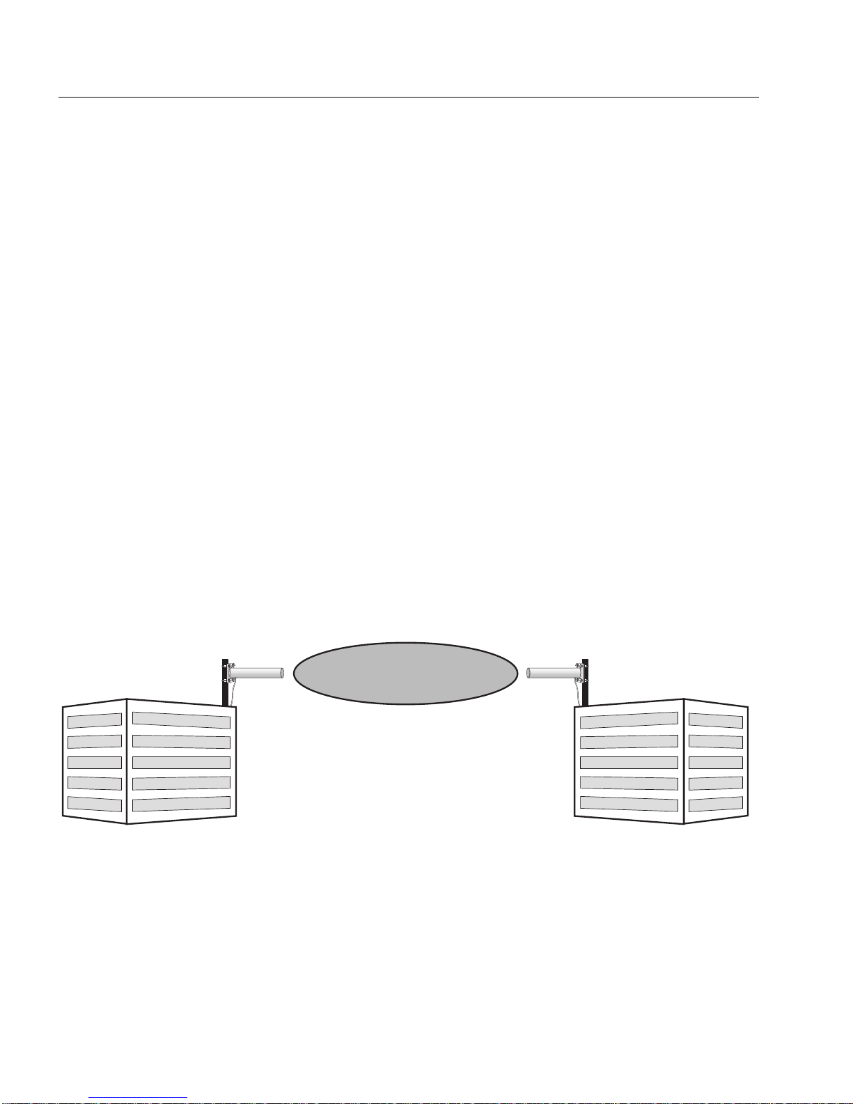
Line of sight
Building A
Spread spectrum systems for LANs are complete p oint-to-point systems and require a
clear line of sight from location to location. Zone widths of the beam depend on the
distance between the antennas. The defined radius is an ar ea that is widest at its center.
The table below shows the zone radius required at 2.4 GHz.
Figure 1: Clear Line of Sight
No Obstruction Area
Direct RF Path
100_05
Building B
2

Site Preparation Guide
Antenna height requirements (mast):
•
At least 5 feet (1.5 meters) above the roof line if you are mounting it on a roof.
•
High enough to achieve a line of sight if you are mounting it on the wall of a
building.
Note: The installer is responsible for local building codes .
Line of sight is defined as:
•
No obstacles in the direct path between the two antennas
•
No obstacles within a defined radius around the antenna beam
•
Clear of neighboring buildings, trees, power lines, and other obstructions
3

Site Preparation Guide
Figure 2: Potential Obstacles to Line of Sight (not to scale)
Building blocking line of sight
Power lines blocking line of sight
Trees blocking line of sight
100_02
4

Figure 3: Large Reflecting Surfaces
Large storage tanks which are common in industrial areas
Factors that can reduce antenna range
Large reflecting surfaces that are parallel or partly perpendicular to the radio signal
cause reflections of the radio signal. Examples of reflecting surfaces are buildings with
low-emissivity (low-e) glass, crowded parking lots, water, moist earth, moist
vegetation, and above-ground power or telephone lines.
Site Preparation Guide
100_03
Because surrounding objects such as trees, power lines, other antennas, and the like
seriously reduce efficiency of the antenna, it is very important to mount the antenna as
high and clear of obstacles as possible.
Ensure that the cable between the antenna and lightning arrestor is at least 3 feet (0.9
meters) away from high-voltage or high -current cable .
5

Site Preparation Guide
Required Data for Antenna Installation Company
The Fresnel Zone
You need a clear line-of-sight between antennas to set up an outdoor installation that
meets your requirements in terms of range and throughput performance.
A
wireless outdoor antenna installation that lacks sufficient
NOTE
The shape of the radio beam, also defined as the Fresnel Zone, is bulged in the middle.
The exact shape and width of the Fresnel Zone is determined by the path length and
frequency of the radio signal.
If any significant part of the Fresnel Zone is obstructed, a portion of radio energy is
lost, resulting in reduced performance. For opti mal performance, you mu st ensure that
the antenna products you choose, in combination with the height of the antenna
installation above ground, will provide sufficient clearance to allow your antenna
installation to cover the distance between th e two wireless sites.
clearance will suffer from poor performance. When radio
performance is poor, the network response is poor as well, due to
many retransmission attempts of lost data frames.
As shown in Figure 4, there are two major variables that determine the shape of the
Fresnel Zone:
•
The distance between the antennas (1).
•
The minimum clearance required for optimal performance (2).
6

Figure 4: Fresnel Zone
Site Preparation Guide
Cable
Length
A
R
o
a
m
A
b
o
u
t
1
2
Cable
Length
B
R
o
a
m
A
b
o
u
t
1
2
2844-01-03A
Refer to the following table to determine the minimum clearance required for your
installation as defined by the distance between the antennas.
Distance Between Antennas (1) Minimum Clearance Required (2)
kilometers (miles) meters (feet)
2.1 (1.3) 5.8 (19.1)
3.5 (2.2) 7.8 (25.7)
6.5 (4.0) 11.1 (36.5)
9.6 (6.0) 14.4 (47.4)
7

Site Preparation Guide
Other Considerations
The strength of each transmitted signal must be considered when planning your
antenna installation. Two parameters are usually listed to indicate transmitted signal
strength: output power of the radio transmitter, and gain of the antenna system.
• Output Power of radio equipment is often subject to maximum lim its as
defined by local radio regulations. Consequently output power is not by
definition the way to enhance wireless performance.
• High gain antennas are larger in size than low gain antennas, and are
characterized by a narrow focus of the radio beam. These two ch aracteristics
make it more difficult to aim the antennas, and/or adjust antenna alignment to
optimize the performance of the wireless point-to-point link.
With these points in mind, the design of antennas and components supplied with the
RoamAbout Outdoor Kit are ba sed upon the following principles:
• An output power and antenna gain that comply with the maximum limits as
defined by local governing bodies concerning radio transmissions.
• Enhanced radio sensitivity for optimal reception o f RoamAbout radio signals
transmitted by remote antennas.
The following distances are required before contacting the Antenna Installation
Company:
Distance between the antennas:
Cable length needed at building A:
Cable length needed at building B:
Height of building A:
Height of building B:
All possible obstacles which can
interfere with the defined radius.
8

Antenna Options
RoamAbout 14-dBi Directional Antenna
The RoamAbout 14-dBi Directional Antenna is a high-gain antenna for the 2.4 GHz
frequency band.
The antenna is a totally enclosed 16-element Yagi designed for point-to-point
communications.
It has a typical VSWR of 1. 5:1 and is less th an 2:1 over the entire fr equency band. The
gain is 14-dBi and the half-power beamwidth is 30 degrees. This antenna is normally
mounted on a mast and is vertically polarized.
Site Preparation Guide
9

Site Preparation Guide
Mechanical
•
Size
•
Mounting Method
Cable
•
Type
•
Length
•
Color
Connector
•
FCC Countries
•
ETSI C ountries
•
France
•
Japan
Electrical
•
Frequency Range
•
VSWR
•
Nominal Impedance
•
Gain
•
Front-to-Back Ratio
•
Half-Power
Beamwidth
•
Vertical (E-plane °)
•
Horizontal (H-plane °)
•
Polarization
Antenna Environment
•
Operating Temperature
•
Wind/survival (mph)
•
Wind Surface Area
45.7 cm (18 in)
•
Vertical mast with an outside diameter
between 35 mm (1.4 in) and 42 mm (1.6
in) using u-bolts.
•
Wall using plugs and screws.
RG-58A/U, 50 ohm low-loss coax
20 cm (7.5 in)
White
Reverse Polarity-N (Male)
Standard-N (Female)
Standard-N (Female)
Standard-N (Female)
2.4 GHz
Less than 2:1, 1.5:1 Nominal
50 Ohms
14-dBi
greater than 20 dB
(-3dB)
30.8 Degrees
31.4 Degrees
Linear, Vertical or Horizontal
+60°C (140°F) - 40°C (-40°F)
At least 128 km/h (80 mph)
7.56 square cm (0.248 square ft)
a
a. At least 104 km/h (65 mph) with 1.25 cm (0.5 in) ice.
10

Figure 5: Typical Outdoor Yagi Configuration
Low Loss
Cable (2)
Wall Mount
Enclosure (3)
Cabletron
Systems
Site Preparation Guide
Antenna (1)
OUTDOOR
INDOOR
Ground Strap
Pigtail Connection (4)
Access Point (5)
Adapter Card (6)
Ethernet
Connection
Lightning Protector (7)
Power Transformer
(included with Access Point)
Power
Connection
11

Site Preparation Guide
The following lists components and part numbers typically used in an outdoor antenna
configuration. Refer to the RoamAbout web site listed on page iii for the latest
information.
# Packaged Kit/
Component
Component Part Numbers by Domain
FCC ETSI* France &
Japan
Spain
OUTDOOR
ANTENNA KIT
Contents:
1 Antenna CSIES-AA-Y14 CSIES-AB-Y14 CSIES-AB-Y14 CSIES-AB-Y14
2
50’ Low-Loss Cable
3 Wall Mount Enclosure CSIAP-WM CSIAP-WM CSIAP-WM CSIAP-WM
4 Pigtail Connection CSIES-AA-PT50 CSIES-AB-PT50 CSIES-AB-PT50 CSIES-AB-PT50
5 Access Point CSIAP-CA CSIAP-CA CSIAP-CA CSIAP-CA
6 Adapter Card CSIBB-AA CSILB-AB CSILB-AF CSILB-AJ
7 Lightning Protector CSIES-AA-LP CSIES-AB-LP CSIES-AB-LP CSIES-AB-LP
*European Telecommunications Standards Institute
**20’ and 75’ Low-Loss cables are also available.
**
CSIEB-AA CSIEB-AB CSIEB-AF CSIEB-AJ
CSIES-AA-C50 CSIES-AB-C50 CSIES-AB-C50 CSIES-AB-C50
12

RoamAbout 7-dBi Omni-Directional Antenna
The RoamAbout 7-dBi Omni-Direc ti o nal Ant enna is a broadb and an tenna for the 2.4
GHz frequency band featuring an omni-directional pattern with a nominal gain of 7
dBi.
This antenna is encapsulated in a wea therproof protective covering. W ith the hardware
provided, this vertically-polarized antenna can be mounted on an antenna mast with an
outside diameter of up to 51mm (2 in).
Mechanical
•
Size
•
Mounting method
Cable
•
Type
•
Length
•
Color
Connector
•
FCC Countries
•
ETSI C ountries
•
France
•
Japan
Electrical
•
Frequency Range
•
VSWR
•
Nominal Impedance
•
Gain
•
Polarization
Antenna Environment
•
Operating Temperature
•
Wind/survival (mph)
• Wind Surface Area
45.7 cm (18 in)
Clamps to vertical mast with outside
diameter up to 51mm (2 in)
RG-58A/U, 50 ohm low-loss coax
15 cm (6 in)
White
Reverse Polarity-N (male)
Standard-N (female)
Standard-N (female)
Standard-N (female)
2.4 GHz
Less than 2:1 Nominal
50 Ohms
7-dBi
Linear Vertical
+60°C (140°F) - 40°C (-40°F)
At least 128 km/h (80 mph)
7.56 square cm (0.248 square feet)
Site Preparation Guide
a
a. At least 104 km/h (65 mph) with 1.25 cm (0.5 in) ice.
13

Site Preparation Guide
Figure 6: Typical Omni-Directional Antenna Configuration
Low Loss
Cable (2)
Antenna and Cable (1)
OUTDOOR
Wall Mount
Enclosure (3)
Pigtail Connection (4)
Access Point (5)
Adapter Card (6)
# Component
1 7-dBi Omni-Directional Antenna
2 Low-Loss Cable: 6m (20 ft), 15m (50 ft), or 22m (75 ft)
3 Wall Mount Enclosure
Ethernet
Connection
INDOOR
Ground Strap
Lightning Protector (7)
Power Transformer
(included with Access Point )
Power
Connection
4 Pigtail Connection
5 Access Point
6 Adapter Card
7 Lightning Protector
14

Verify Component Connector Polarity
The components supplied with your Ou tdoor Antenna Kit are configured with either
Standard-N connectors or Reverse Polar ity-N connectors, subject to the country wh ere
the kit was purchased. Refer to the following table to verify that the polarity of each
connector is correct for your installation.
21
Pigtail
Connection
(A)
Lightning
Protector
(B)
Low-Loss
Cable
(C)
Site Preparation Guide
Antenna
Cable
(D)
ETSI Countries, France, Spain, and
Japan
Standard-N Male
Standard-N Female
A
B
C
D
1 - PC Card connector 1 - PC Card connector
2 - Standard-N Male 2 - Reverse Polarity-N Female
Standard-N Female on both ends Reverse Polarity-N Male on both ends
Standard-N Male on both ends Reverse Polarity-N Female on both ends
Standard-N Female Reverse Polarity-N Male
The term Male or Female does not refer to the connector thread,
NOTE
but to its center pin.
• Male connectors have a solid
FCC Countries
Reverse Polarity-N Female
Reverse Polarity-N Male
center pin.
If you wish to purchase individual components, make sure you specify the correct
N-Type connectors to match the configuratio n that applies to your country.
• Female connectors have a hollow
center pin
15

Site Preparation Guide
Reviewing the Site Preparation Checklist
Lightning protection
√
√
Determine the mounting location fo r the lightning rod (positioned near the antenna).
Ensure an earth ground location for the antenna structure and lightning arrestor.
Mounting requirements
√
√
Determine the type of mounting that is required (trip od, wall m ount, etc.)
Consider that three guy wires are needed for each 1 0-f oot (3 meter) section of the mast;
for example, 20 feet of mast requires six guy wires.
Line of sight
√
√
√
√
√
Determine the mounting location for the ante nna.
Ensure that the back of the antenna is clear.
Ensure that remote and local antennas can see each other.
Ensure that no obstacles are in the direct path or within the de fined zone of the two sites.
Consider whether any RF interference is present.
Installation Requirements
√
√
√
√
√
16
Determine the best location for the Access Point.
Determine the length of cable required from the antenna to the Access Point.
Ensure the location has an accessible Ethernet connection.
Ensure the location has accessible power.
Determine the distance between buildings.

For Additional Assistance
If you are purchasing your system through a Channel Partner, contact that Channel
Partner for assistance.
If you are purchasing your sy stem f rom Cabl etron, co ntact Cabl etro n using one of t he
following methods:
Site Preparation Guide
World Wide Web
Phone (603) 332-9400
Internet mail
FTP ft p://f tp.c ab let ron.c om /
Login
Password
To send comments or suggestions concerning this document, contact the
Cabletron Systems Technical Writing Departmen t via the following
email address: TechWriting@cabletron.com
Make sure to include the document Part Number in the email message.
http://www.cabletron.com
http://www.cabletron.com/wireless
http://www.cabletron.com/support/forms
/email-suppo r t.for m
anonymous
your email address
17

 Loading...