

Page 1

Installing and Using
for Solstice Enterprise Manager
on Solaris
Title Page
®
Page 2

Page 3

Notice
Cabletron Systems reserves the right to make changes in speciÞcations and other information
contained in this document without prior notice. The reader should in all cases consult Cabletron
Systems to determine whether any such changes have been made.
The hardware, Þrmware, or software described in this manual is subject to change without notice.
IN NO EVENT SHALL CABLETRON SYSTEMS BE LIABLE FOR ANY INCIDENTAL, INDIRECT,
SPECIAL, OR CONSEQUENTIAL DAMAGES WHATSOEVER (INCLUDING BUT NOT LIMITED
TO LOST PROFITS) ARISING OUT OF OR RELATED TO THIS MANUAL OR THE
INFORMATION CONTAINED IN IT, EVEN IF CABLETRON SYSTEMS HAS BEEN ADVISED OF,
KNOWN, OR SHOULD HAVE KNOWN, THE POSSIBILITY OF SUCH DAMAGES.
Virus Disclaimer
Cabletron has tested its software with current virus checking technologies. However, because no
anti-virus system is 100% reliable, we strongly caution you to write protect and then verify that the
Licensed Software, prior to installing it, is virus-free with an anti-virus system in which you have
conÞdence.
Cabletron Systems makes no representations or warranties to the effect that the Licensed Software is
virus-free.
Copyright © 1998 by Cabletron Systems, Inc. All rights reserved.
Printed in the United States of America.
Order Number: 9032445-E3 October 1998
Cabletron Systems, Inc.
35 Industrial Way, P.O. Box 5005
Rochester, NH 03867-0505
SPECTRUM, MiniMMAC, FNB, Multi Media Access Center,
and
Portable Management Application, IRM, IRM2, IRM3, IRBM, ETSMIM, EFDMIM, EMME,
ETWMIM, FDMMIM, FDCMIM, MRXI, MRXI-24, NB20E, NB25E, NB30, NB35E, SEHI,
TRBMIM, TRMM, TRMMIM, TRXI, Media Interface Module, MIM,
are trademarks of Cabletron Systems, Inc.
UNIX
and
trademarks of the Open Software Foundation, Inc.
Massachusetts Institute of Technology.
Apple
trademark of Banyan Systems, Inc.
Corporation.
of CompuServe.
OpenWindows
OPENLOOK
and
AppleTalk
Novell
Sun Microsystems
are trademarks of Sun Microsystems, Inc.
is a trademark of Unix System Laboratories, Inc.
X Window System
Ethernet
are registered trademarks of Apple Computer, Inc.
DEC
net is a registered trademark of Digital Equipment
is a registered trademark of Novell, Inc.
is a registered trademark, and
and
XNS
and
DNI
are registered trademarks,
and
Flexible Network Bus
OSF/Motif
is a trademark of
are trademarks of Xerox Corporation.
Banyan
CompuServe
is a registered trademark
Sun, SunNet
and
is a registered
, and
Motif
are
i
Page 4

Restricted Rights Notice
(Applicable to licenses to the United States Government only.)
1. Use, duplication, or disclosure by the Government is subject to restrictions as set forth in
subparagraph (c) (1) (ii) of the Rights in Technical Data and Computer Software clause at
DFARS 252.227-7013.
Cabletron Systems, Inc., 35 Industrial Way, Rochester, New Hampshire 03867-0505.
2. (a) This computer software is submitted with restricted rights. It may not be used,
reproduced, or disclosed by the Government except as provided in paragraph (b) of this
Notice or as otherwise expressly stated in the contract.
(b) This computer software may be:
(1) Used or copied for use in or with the computer or computers for which it was
acquired, including use at any Government installation to which such computer or
computers may be transferred;
(2) Used or copied for use in a backup computer if any computer for which it was
acquired is inoperative;
(3) Reproduced for safekeeping (archives) or backup purposes;
(4) Modified, adapted, or combined with other computer software, provided that the
modified, combined, or adapted portions of the derivative software incorporating
restricted computer software are made subject to the same restricted rights;
(5) Disclosed to and reproduced for use by support service contractors in accordance
with subparagraphs (b) (1) through (4) of this clause, provided the Government
makes such disclosure or reproduction subject to these restricted rights; and
(6) Used or copied for use in or transferred to a replacement computer.
(c) Notwithstanding the foregoing, if this computer software is published copyrighted
computer software, it is licensed to the Government, without disclosure prohibitions, with
the minimum rights set forth in paragraph (b) of this clause.
(d) Any other rights or limitations regarding the use, duplication, or disclosure of this
computer software are to be expressly stated in, or incorporated in, the contract.
(e) This Notice shall be marked on any reproduction of this computer software, in whole or in
part.
ii
Page 5

Chapter 1 Introduction to SPECTRUM
for Solstice Enterprise Manager on Solaris
Using this Guide .....................................................................................1-2
WhatÕs NOT in this Guide . . .........................................................1-4
Year 2000 Compliance ............................................................................1-4
Conventions.............................................................................................1-5
Screen Displays ................................................................................1-5
Launching Documentation.............................................................1-7
Using the Mouse ..............................................................................1-8
Getting Help ............................................................................................1-9
Chapter 2 Installing SPECTRUM for
Solstice Enterprise Manager
Installation Prerequisites .......................................................................2-2
Preparing Your Workstation for Installation.......................................2-3
To Install from a Local CD-ROM Drive........................................2-4
To Install from a Remote CD-ROM Drive....................................2-5
Installing SPMA ......................................................................................2-7
Integrating SPMA with Solstice Enterprise Manager...............2-13
Choices to Make During Integration ...................................2-13
Choosing Not to Integrate.....................................................2-14
Specifying a Database Storage Directory:
CTRONDB (optional).............................................................2-14
Copying the Necessary Files to a Custom CTRONDB
Directory...........................................................................2-16
A Note About Environment Variables
(For Previous Users Only!).............................................2-17
Testing for and Correcting Potential NIS Problems..................2-18
Contents
iii
Page 6

Contents
Using SPMA Applications in a Stand-alone Mode ......................... 2-20
WhatÕs Next?......................................................................................... 2-21
Chapter 3 Getting Started
Creating Cabletron Network Objects.................................................. 3-1
Using the SPMA Discover Application............................................... 3-2
Launching SPMA Discover ........................................................... 3-3
SPMA Discover and SmartSwitch 9000 Devices................. 3-4
Manually Creating a Cabletron Systems Glyph................................ 3-4
ConÞguring Cabletron Glyph Properties........................................... 3-5
Assigning a Device Name ............................................................. 3-7
Assigning or Editing Community Names................................... 3-8
Selecting MIB Agent Files.............................................................. 3-9
Manually Creating SmartSwitch 9000 Module and
Chassis Glyphs....................................................................... 3-10
A Few Words about MIB Components
and Community Names ........................................................3-11
Starting SPMA Tools and Applications............................................. 3-12
Launching Documentation.......................................................... 3-13
Chapter 4 Using the Stand-alone Launcher
About the Stand-alone Launcher......................................................... 4-2
Adding Devices to the Launcher Database........................................ 4-6
Adding Devices Individually........................................................ 4-6
Assigning an Appropriate Community Name.................... 4-9
Adding a SmartSwitch 9000 Chassis...........................................4-11
A Special Note About the SmartSwitch 9500..................... 4-13
Using the Discover Tool............................................................... 4-13
Discover Parameters ............................................................. 4-15
Adding and Deleting SNMP Community Names............ 4-17
Adding and Deleting IP Address Ranges .......................... 4-18
Setting the Discover Parameters.......................................... 4-19
Starting the Discovery Process.................................................... 4-20
iv
Page 7

The SPMA Launcher Database........................................................... 4-22
Changing the Polling Rate........................................................... 4-23
Sorting the Devices Listed in the Database............................... 4-24
Deleting Devices from the Database.......................................... 4-24
Using the Restore Button............................................................. 4-24
Launching Applications...................................................................... 4-25
Launching Applications from the Command Line.................. 4-25
Customizing Launcher Menus........................................................... 4-26
Adding Access to Third-party Applications............................. 4-26
Viewing Documentation..................................................................... 4-28
Appendix A Cabletron Device MIB Agents
ConÞguring a Manually-Created Glyph ........................................... A-1
Cabletron Device MIB Agent Tables .................................................. A-2
MMAC and Standalone Devices ................................................. A-2
BRIM/HSIM Modules .................................................................. A-8
SmartSwitch 9000 Devices............................................................ A-9
Creating and Using the Generic SNMP Glyph............................... A-12
Contents
Index
v
Page 8

Contents
vi
Page 9

Chapter 1
Introduction to SPECTRUM for Solstice Enterprise Manager on Solaris
How to use this guide; manual conventions; contacting the Cabletron Systems Global
Call Center
SPECTRUM¨ for Solstice Enterprise Manager (SEM) adds
comprehensive remote management support for all of Cabletron
SystemsÕ intelligent network management devices to Sun
MicrosystemsÕ Solstice Enterprise Manager network management
platform. The result is a versatile network management system,
ideally suited to managing networks that contain Cabletron Systems
devices.
At the heart of SPECTRUM for SEM are the graphical Hub and
Bridge views Ñ interactive displays of Cabletron Systems intelligent
network devices and, where applicable, the hubs and modules they
control. In addition to their graphical displays of device status and
conÞguration, the Hub and Bridge views provide a wide variety of
statistical information about the trafÞc passing through your devices,
and provide access to a number of separate applications that allow
you to monitor and manage each of the functions your intelligent
devices can perform. Additional applications not available through
the Hub or Bridge views can be accessed, like the Hub and Bridge
1-1
Page 10

Introduction to SPECTRUM for Solstice Enterprise Manager on Solaris
views themselves, via the
stand-alone mode, from the Stand-alone Launcher or the command
line.
SPECTRUM for SEM also expands the graphical reporting
capabilities of Solstice Enterprise Manager by providing pie chart and
meter tools that allow you to dynamically display network data and
performance statistics. You can run and control these visual tools
through menu choices and dialog boxes within the SPECTRUM for
SEM graphical user interface, or execute them in a stand-alone mode
from the command line, specifying both the variables to depict and
the properties of the chart or meter itself. The pie chart and meter
tools are more thoroughly described in the
Meters
Application (SPMA) Tools Guide
Using this Guide
This manual is designed to complement the Solstice Enterprise
Manager manual set from Sun Microsystems, as well as the
Tools Guide
the
SPMA System Message Reference Guide
device- and application-speciÞc
install SPECTRUM for SEM, how to discover Cabletron devices on
your network and how to properly deÞne the glyphs that represent
them, and how to access the
to each individual application available for your device. The
Enterprise Manager UserÕs
the basic features of Solstice: creating your network and network
components, retrieving network data, specifying events, and so forth;
the
SPMA Tools Guide
application-speciÞc
how to operate each of the management applications available for
your Cabletron intelligent devices; and the
Guide
provides some guidelines that can help you interpret the
statistical data provided by SPMA about the trafÞc on your network.
chapter of the
, the
Cabletron SystemsÕ Network Troubleshooting Guide
UserÕs Guides
Glyph
SPECTRUM Portable Management
and the individual device- and
menu; or, for operation in
Charts, Graphs, and
.
, and the individual
UserÕs Guides
Glyph
and
menu, which serves as a gateway
Reference
provide detailed information on
guides describe how to use
Network Troubleshooting
; it describes how to
SPMA
,
Solstice
1-2 Using this Guide
Page 11

Introduction to SPECTRUM for Solstice Enterprise Manager on Solaris
The
System Message Reference Guide
of error and informational messages you may see; corrective user
action is also provided, where appropriate.
This manual assumes that you have a basic understanding of
network management concepts and that you are familiar with Solaris,
a Sun Microsystems version of the UNIX operation system, and the
window manager (OpenWindows or the Common Desktop
Environment) you have selected.
explains the source of a variety
¥ Chapter 1,
Manager on Solaris
and the conventions used here and in other SPMA manuals,
explains where to Þnd information about SPMA applications and
device management modules, and tells you how to contact the
Cabletron Systems Global Call Center.
¥ Chapter 2,
Manager
SPECTRUM for Solstice Enterprise Manager, and outlines the
procedures for installing SPECTRUM Portable Management
Applications for use in conjunction with Solstice Enterprise
Manager and in a stand-alone mode.
¥ Chapter 3,
to create Cabletron Systems device glyphs in your Solstice
Enterprise Manager database, how to create device glyphs from
scratch without using SPMA Discover, and how to conÞgure your
glyphs to make the most of the features and functions available on
each Cabletron device.
¥ Chapter 4,
the SPMA Stand-alone Launcher, how to access SPMA
applications from the command line, and how to add third party
applications to the Launcher menu; some basic information about
MIB components and community names is also provided.
Introduction to SPECTRUM for Solstice Enterprise
, describes this
Installing SPECTRUM for Solstice Enterprise
, lists the hardware and software requirements for using
Getting Started
Using the Stand-alone Launcher
, explains how to use SPMA Discover
Installing and Using ...
, explains how to use
guide
¥ Appendix A,
provides a list of the ASN1 and GDMO Þles applicable to each
Cabletron management device supported by SPMA; refer to this
list when conÞguring glyphs for your Cabletron intelligent
Selecting MIB Agent Files for Cabletron Devices
Using this Guide 1-3
,
Page 12

Introduction to SPECTRUM for Solstice Enterprise Manager on Solaris
devices. This Appendix also describes how to create a generic
SNMP icon for general SNMP stack management of third-party
devices.
What’s NOT in this Guide . . .
This guide is intended to provide you with the information you need
to install SPECTRUM for SEM on your workstation, locate Cabletron
devices on your network and properly deÞne their glyphs, and access
the
Glyph
applications available for a particular device.
What you wonÕt Þnd in this guide are any detailed, step-by-step
instructions on how to use the applications available for each of your
devices; or how to discover devices and create a map or maps in
Solstice Enterprise Manager. The latter can be found in your Solstice
Enterprise Manager documentation; the former is located either in the
SPMA Tools Guide
which are common to most devices, or in the device- and
application-speciÞc
the applications available to each device. The entire document set Ñ
including this
electronic format; all appropriate documents are installed for you
automatically.
menu, which provides a gateway to each of the
, which describes the operation of applications
SPMA UserÕs Guides
Installing and Using...
, which describe the rest of
guide Ñ is provided in an
This guide also includes instructions for installing SPECTRUM for
SEM for operation in a stand-alone mode; instructions for starting
each application from the command line are included in each chapter,
both in the device- and application-speciÞc guides and in the
Tools Guide.
SPMA
Year 2000 Compliance
Previous users of SPMA will note a few display changes related to
Year 2000 compliance. All SPMA applications now have the ability to
display a four-digit year value where this information is available.
For example, the Stand-alone Launcher window Ñ which uses your
1-4 Year 2000 Compliance
Page 13

Introduction to SPECTRUM for Solstice Enterprise Manager on Solaris
workstationÕs system time value to display the time and date of the
last contact change Ñ will now display these date values with eight
digits (05/31/1998) instead of six (05/31/98).
Please keep in mind, however, that SPMAÕs ability to
four-digit year value in device-speciÞc windows Ñ such as the
Device Status window available from the Hub View or the Bridge
View Ñ is dependent on the ÞrmwareÕs ability to
value. Not all Þrmware versions support this ability; contact
Cabletron SystemsÕ Global Call Center for information speciÞc to
your device Þrmware.
Conventions
The family of SPECTRUM Portable Management Applications can
work with a number of different network management systems
running on several different operating systems and graphical user
interfaces. This versatility presents two documentation problems:
Þrst, there is no standard terminology; and second, the appearance of
the windows will differ based on the graphical interface in use. For
the sake of consistency, the following conventions will be followed
throughout this and other SPMA guides.
Screen Displays
SPMA runs under a variety of different operating systems and
graphical user interfaces. To maintain a consistent presentation,
screen displays in this and other SPMA guides show an OSF/Motif
environment. If youÕre used to a different GUI, donÕt worry; the
differences are minor. Buttons, boxes, borders, and menus displayed
on your screen may look a bit different from what you see in the
guide, but theyÕre organized and labelled the same, located in the
same places, and perform the same functions in all screen
environments.
display
provide
a
a four-digit
Some windows within SPMA applications can be re-sized; those
windows will display the standard window resizing handles
employed by your windowing system. Re-sizing a window doesnÕt
Conventions 1-5
Page 14
Introduction to SPECTRUM for Solstice Enterprise Manager on Solaris
re-size the information in the window; it just changes the amount of
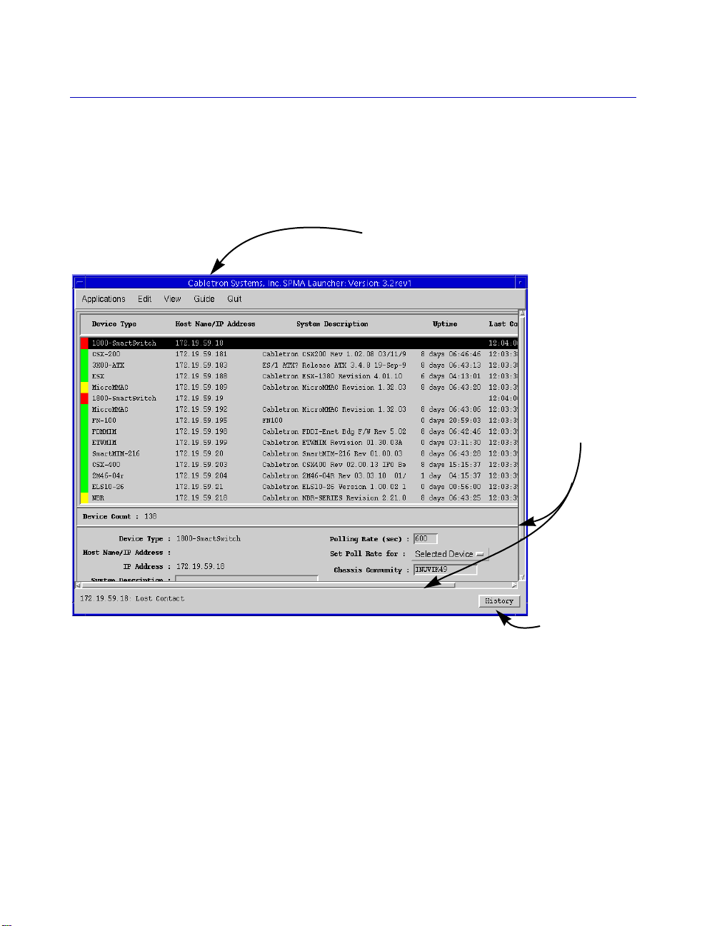
information that can be displayed (see Figure 1-1). When you shrink a
window, scroll bars will appear as necessary so that you can scroll to
view all the information that is available.
Select the Guide menu option to launch
a menu of available documents
Use the scroll
bars provided
to choose what
to display in a
window that’s
been resized
Click here to
display footer
message
history
Figure 1-1. Window Conventions
Some windows will also contain a
button launches a History window (Figure 1-2) which lists all footer
messages that have been displayed since the window was Þrst
invoked. This window can help you keep track of management
actions you have taken since launching a management application.
History
button; selecting this
1-6 Conventions
Page 15

Introduction to SPECTRUM for Solstice Enterprise Manager on Solaris
Figure 1-2. The History Window
Launching Documentation
The SPMA documentation set is now provided in electronic format
and installed with your SPMA program Þles, along with AdobeÕs
Acrobat Reader application. The
available in many application windows Ñ including all Hub Views,
the Bridge View, and the Stand-alone Launcher Ñ will launch the
Acrobat Reader and open the appropriate document. From the
Stand-alone Launcher, clicking the
Þle which provides links to all other available documentation; you
can also access this menu Þle (called
the Solstice Manager Viewer window via the
menu option. Any document Þle can also be opened directly via
Acrobat. Document Þles are stored in the
documentation
directory.
Conventions 1-7
Guide
button or menu option
Guide
button will launch a menu
SPMAdocs.pdf
ToolsÑ>SPMA Guide
/usr/ctron/
) directly from
Page 16

Introduction to SPECTRUM for Solstice Enterprise Manager on Solaris
Using the Mouse
The UNIX mouse has three buttons. Procedures within the SPMA
document set refer to these buttons as follows:
Button 1
Button 2
Button 3
Figure 1-3. Mouse Buttons
If youÕre using a two-button mouse, donÕt worry. SPMA doesnÕt make
use of mouse button 2. Just click the left button for button 1 and the
right mouse button when instructed to use mouse button 3.
Whenever possible, we will instruct you on which mouse button to
employ; however, menu buttons within SPMA applications will
operate according to the convention employed by the active
windowing system. By convention, menu buttons under the Motif
windowing environment are activated by clicking the left mouse
button (referred to as mouse button 1 in SPMA documentation), and
there is no response to clicking the right button (mouse button 3).
Under OpenWindows, menu buttons can be activated by clicking the
right button, and convention dictates that the left button activates a
default menu option; within SPMA, that default option will also
display the entire menu. Because of this difference, references to
activating a menu button will not include instructions about which
1-8 Conventions
Page 17

Introduction to SPECTRUM for Solstice Enterprise Manager on Solaris
Getting Help
mouse button to use. All other panels from which menus can be
accessed, and all buttons which do not provide access to menus, will
operate according to SPMA convention, as documented.
If you need additional support related to SPMA, or if you have any
questions, comments, or suggestions related to this manual, contact
the Cabletron Systems Global Call Center. Before calling, please have
the following information ready:
¥ The product name
¥ The version number of the program that you need help with.
SPMA is modular, which means each application will have a
speciÞc revision number. Where applicable, an INFO button
provides the version number; you can also view the version
number for any application by typing the command to start the
application followed by a -v.
You can contact the Cabletron Systems Global Call Center by any of
the following methods:
By phone: (603) 332-9400
24 hours a day, 365 days a year
By mail: Cabletron Systems, Inc.
PO Box 5005
Rochester, NH 03866-5005
By Internet mail: support@ctron.com
By FTP ctron.com (134.141.197.25)
Login
Password
By BBS: (603) 335-3358
Modem Setting 8N1: 8 data bits, 1 stop bit, No parity
anonymous
your email address
Getting Help 1-9
Page 18

Introduction to SPECTRUM for Solstice Enterprise Manager on Solaris
For additional information about Cabletron Systems products, visit
our World Wide Web site: http://www.cabletron.com/. For technical
support, select Service and Support.
1-10 Getting Help
Page 19

Chapter 2
Installing SPECTRUM for Solstice Enterprise Manager
Hardware and software requirements; installation procedures; installing SPMA modules
for stand-alone operation
Beginning with the 3.2rev1 release, SPMA applications are now sold
and shipped as a single part number which includes all available
applications and device support. The Þles that will be extracted from
the SPECTRUM Portable Management Application (SPMA) CD that
you received will depend on which modules you choose to install.
Along with the core applications (including the Stand-alone
Launcher, the SPMA tool set, and the Solstice Enterprise Manager
interface Þles) and the individual device modules you choose, the
installation procedure will also install all related documentation and
the version of AdobeÕs Acrobat Reader appropriate to your operating
system. If you are a previous user of SPMA, you will notice a few
new steps at the beginning of the install process; the rest of the
process is unchanged.
This chapter divides the installation procedure into separate tasks:
Preparing Your Workstation for Installation
Before you run the Install script included on your SPECTRUM
Portable Management Application CD, there are several operating
parameters you must set on your workstation.
2-1
Page 20

Installing SPECTRUM for Solstice Enterprise Manager
Installing SPMA Files on your Workstation
Whether youÕre installing SPECTRUM for Solstice Enterprise
Manager on Solaris for the Þrst time, or installing an additional
device module or product upgrade, you follow the same simple
procedure to install the SPMA Þles on your workstation Ñ including
choosing the modules you wish to install. All necessary directories
and subdirectories are created for you automatically, and all
appropriate documentation is installed along with the chosen
modules.
Integrating SPMA with Solstice Enterprise Manager
You must also update a number of Solstice Þles and directories so that
they contain the Cabletron information required to run SPMA.
Creating Environment Variables
If you wish, you can deÞne the variable CTRONDB to store your
SPMA-related database Þles in other than the default location.
Testing for and Correcting Potential NIS Problems
Certain SPMA applications make frequent use of IP address to host
name mapping, which can slow application response time on some
networks. The SPMA pnisd daemon is designed to enhance this
response time on networks where this is a problem; we tell you how
to test your network, and how to install the daemon if you need it.
Installation Prerequisites
Before you install SPMA, you must already have installed Solstice
Enterprise Manager from Sun Microsystems. The SPMA installation
creates some new directories and adds Þles to existing Solstice
Enterprise Manager directories. You install the entire product Ñ
including all related documentation Ñ from a single CD; all
necessary directories are created for you automatically.
Hardware Requirements
SPMA requires a minimum of 48 megabytes of RAM, but 64 is
recommended. At a minimum, swap space should be equal to twice
the amount of RAM; however, if you plan to run several SPMA
2-2 Installation Prerequisites
Page 21

Installing SPECTRUM for Solstice Enterprise Manager
applications simultaneously, you may improve performance by
assigning additional swap space. The SPMA core product and device
modules require hard disk space as speciÞed below:
SPMA Core 71 megabytes
Device modules from 4 to 43 megabytes; average size 27
megabytes
Entire product 248 megabytes
Be sure you have enough hard disk space over and above that
required by Solstice Enterprise Manager to install the modules you
need; note that size estimates include space for the associated
documentation.
Software Requirements
SPMA has the following operating system and windowing system
software requirements:
Solaris version 2.5.1 or 2.6
OpenWindows Version 3 (3.5.1 via showrev -v)
CDE version 1.0.2
Solstice Enterprise Manager version 2.0
Preparing Your Workstation for Installation
Before you can successfully run the install script from the SPMA
CD-ROM, there are several parameters you must set for your
workstation. You must run the install as root; therefore, if display
parameters have not been set for root, you may need to set the
display environment variable to the hostname of your workstation.
You may also need to give root permission to display the install
windows by using the xhost command. These and other steps
necessary to execute before installing from a local or remote CD-ROM
drive are described below.
Preparing Your Workstation for Installation 2-3
Page 22

Installing SPECTRUM for Solstice Enterprise Manager
To Install from a Local CD-ROM Drive
1. Log on to the workstation as root.
If you are running on Solaris with the vold process (volume manager
NOTE
daemon), skip steps 2 and 3 below. When you insert a CD on a system
running the volume manager daemon, the CD filesystem is automatically
mounted by the system.
2. Create a directory for the CD mount point by typing:
mkdir /cdrom
3. Insert the CD into the CD-ROM drive and mount the CD
filesystem using the following command:
mount -r -F hsfs /dev/sr0 /cdrom
4. Chec k to mak e sure that the DISPLAY environment variable is set
to the hostname of your workstation by typing echo $DISPLAY.
If the DISPLAY environment variable is set to <your
workstation’ s hostname>:0.0 or :0.0, y ou do not need to set the
DISPLAY environment variable; proceed to step 5.
If the DISPLAY is set to a hostname other than your own or
not set at all, set the DISPLAY environment variable to the
hostname of your workstation using one of the following
commands:
for C Shell
setenv DISPLAY <hostname>:0
for Korn and Bourne Shell
DISPLAY=<hostname>:0 ; export DISPLAY
2-4 Preparing Your Workstation for Installation
Page 23

Installing SPECTRUM for Solstice Enterprise Manager
5. If you did not start the windowing environment as root you will
also need to give root permission to display by switching to the
username you used to launch the windowing environment, and
typing the following from the command line:
xhost +<hostname>
To Install from a Remote CD-ROM Drive
1. Log on to the CD-ROM host workstation as root.
If you are running on Solaris with the vold process (volume manager
NOTE
daemon), skip steps 2 and 3 below. When you insert a CD on a system
running the volume manager daemon, the CD filesystem is automatically
mounted by the system.
2. Create a directory for the CD mount point by typing:
mkdir /cdrom
3. Insert the CD into the CD-ROM drive and mount the CD
filesystem using the following command:
mount -r -F hsfs /dev/sr0 /cdrom
4. Export the CD ROM filesystem by adding the following line to
your /etc/dfs/dfstab file:
share -F nfs -o ro /cdrom
then type the following from the command line:
shareall
Or just type the following from the command line:
share -F nfs -o ro /cdrom
Preparing Your Workstation for Installation 2-5
Page 24

Installing SPECTRUM for Solstice Enterprise Manager
Adding the line specified above to your /etc/dfs/dfstab file will permanently
TIP
export the CD-ROM filesystem (until the line is removed); exporting from
the command line only will export the CD-ROM filesystem until the next
time you re-boot.
5. Log on to the target workstation as root.
6. Create a directory for the CD mount point by typing:
mkdir /cdrom
7. Chec k to mak e sure that the DISPLAY environment variable is set
to the hostname of your workstation by typing echo $DISPLAY.
If the DISPLAY environment variable is set to <your
workstation’ s hostname>:0.0 or :0.0, y ou do not need to set the
DISPLAY environment variable; proceed to step 8.
If the DISPLAY is set to a hostname other than your own or
not set at all, set the DISPLAY environment variable to the
hostname of your workstation using one of the following
commands:
for C Shell
setenv DISPLAY <hostname>:0
for Korn and Bourne Shell
DISPLAY=<hostname>:0 ; export DISPLAY
8. If you did not start the windowing environment as root you will
also need to give root permission to display by switching to the
username you used to launch the windowing environment, and
typing the following from the command line:
xhost +<hostname>
2-6 Preparing Your Workstation for Installation
Page 25

9. Mount the CDROM drive workstation using the following
command:
if you are using a Solaris machine as the CD drive workstation
mount -r -o hard,intr <remote
hostname>:/cdrom/cdrom0 /cdrom
The commands above and below should each be entered as one line.
NOTE
if you are not using a Solaris machine as the CD workstation
mount -r -o hard,intr <remote hostname>:/cdrom
/cdrom
Installing SPMA
Follow the procedure below to install the SPMA program and
documentation Þles to your workstationÕs hard drive; during
installation, all necessary subdirectories will be created for you
automatically. The following install procedures cover both the initial
installation and any subsequent product additions or upgrades.
Installing SPECTRUM for Solstice Enterprise Manager
During the install process, you must choose which of the available SPMA
NOTE
modules you wish to install; the core applications are installed
automatically. If you choose to install additional modules at a later time, the
core files will automatically be re-installed, but you need not re-install any
individual modules you have already installed.
1. To start the installation, type the following command:
if you are running the volume manager daemon (vold process):
/cdrom/cdrom0/install.cd
if you are not running the volume manager daemon:
/cdrom/install.cd
Installing SPMA 2-7
Page 26
Installing SPECTRUM for Solstice Enterprise Manager
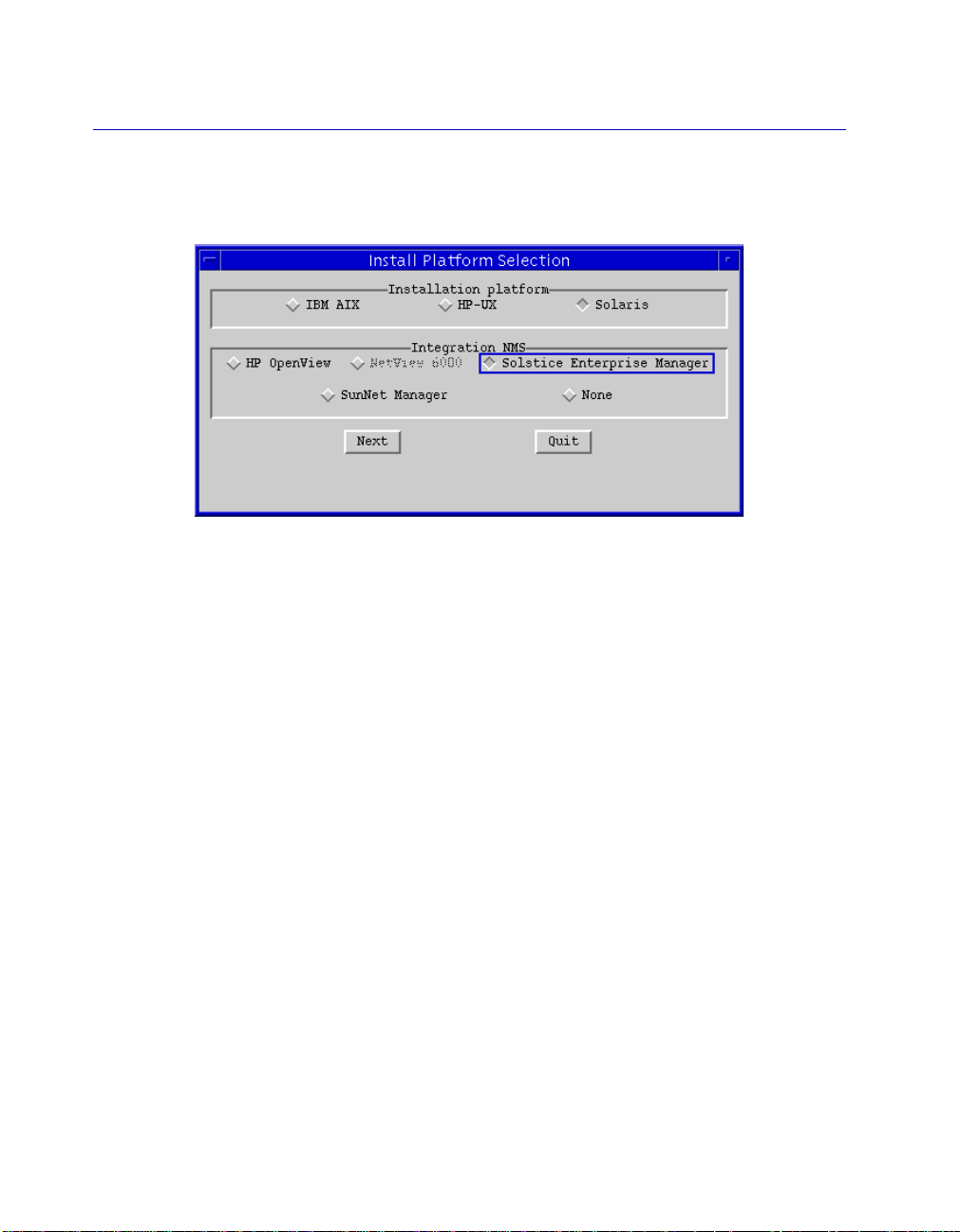
The Install Platform Selection window, Figure 2-1, will be
displayed.
Figure 2-1. The Install Platform Selection Window
2. Click in the appropriate fields to select the operating system and
network management system (if applicable) on which you will be
running the SPMA applications. Based on information read from
your workstation, these fields will try to default to the correct
values; be sure to check the default settings and change them if
necessary.
3. Click on Next to proceed with installation; the Install Product
Selection window, Figure 2-2, will appear. You can use this
window to select only those applications that you need, or you
can leave the default selections and install the entire SPMA
product. The associated document files will be automatically
installed for each selected module. Click mouse button 1 on any
module to select or de-select it. Note that the Core option cannot
be de-selected; core application and documentation files will be
installed automatically each time the installation procedure is run.
You can also double-click on the list box title to select all available
options.
2-8 Installing SPMA
Page 27

TIP
Installing SPECTRUM for Solstice Enterprise Manager
Be sure you have adequate hard disk space to install the options you have
selected; see Hardware Requirements, page 2-2, for module size estimates.
Figure 2-2. Install Product Selection Window
4. Clic k on Ne xt to proceed with installation; an Install Configuration
window like the example shown Figure 2-3 will appear. The
directory you are installing
from
will be displayed in the Install
from: field; the default install directory will be displayed in the
Install to: field.
Installing SPMA 2-9
Page 28

Installing SPECTRUM for Solstice Enterprise Manager
You can also click on Previous to return to the Platform Selection window,
TIP
and change any settings you have made there before continuing with the
install procedure.
Figure 2-3. Install ConÞguration window
If you decide not to go on with the installation at any time, click on Quit
NOTE
from this or any of the preceding windows to stop the installation process.
5. You can change the directory you are installing to by either
clicking on Browse and selecting a new directory, or by typing in
the path of the new directory in the Install to: field.
2-10 Installing SPMA
Page 29

!
CAUTION
Installing SPECTRUM for Solstice Enterprise Manager
We strongly recommend that you install to the default /usr directory.
However, if you choose to install to a different directory, please keep the
following cautions in mind:
First, use care when typing in the directory name Ñ if you mistype the
name, the install will still create the directory for you, and your files may
end up in an unexpected location; if you leave a space at the end of the path
you specify, the install will succeed, but this kind of directory name is not
recommended. If you choose to install to a path other than the default /usr,
we recommend that you first create the directory, then use the Browse
button to select it in this window.
Second, remember that if you install to a directory other than /usr, the
install routine will automatically attempt to create a link from the ctron
directory within the directory you specified to /usr/ctron. If there is
already a file, directory, or link named /usr/ctron, you will receive a
warning message (see Figure 2-4) at the end of the install process indicating
that the link could not be created. If you receive this warning, you must first
either remove or rename the existing /usr/ctron, then manually make
the link by typing the following command from the command line:
ln -s <your install directory>/ctron /usr/ctron
Figure 2-4. Sample Warning Message
For example, if you choose to install to /data instead of the default /usr
directory, the following link must be created either by the install process or
manually after installation:
ln -s /data/ctron /usr/ctron
Installing SPMA 2-11
Page 30
Installing SPECTRUM for Solstice Enterprise Manager
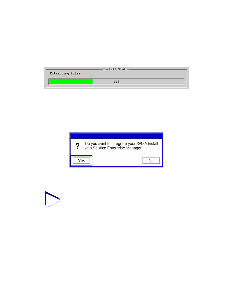
6. To proceed with the installation click on Install. Progress will be
reported via the status bar at the bottom of the Install
Configuration window (see Figure 2-5).
Figure 2-5. Installation Progress Indicator
7. When all of the SPMA application files ha ve been copied, you will
be prompted to integrate SPMA with your network management
system. (See the following section for more information.)
Figure 2-6. Integration window
Under certain special circumstances, you may want to run the install
TIP
procedure without the user interface windows; in order to do this, however,
you must first contact the Global Call Center and request specific
instructions and an extraction key.
2-12 Installing SPMA
Page 31

Installing SPECTRUM for Solstice Enterprise Manager
Integrating SPMA with Solstice Enterprise Manager
Several Solstice Enterprise Manager Þles and directories must be
updated to include the information used to run SPMA. The
integration process which immediately follows the install (or which
can be run independently at any time) performs the following
functions:
¥ Copies the necessary MIB agent and schema Þles and converts
them to the ASN1 and GDMO format required by Solstice
Enterprise Manager.
¥ Copies the necessary glyph Þles to the appropriate directory.
¥ Updates the glyph menu Þle, so that Cabletron glyphs can provide
access to all appropriate management functions.
¥ Copies Cabletron trap information to the trap_maps Þle.
¥ Re-initializes Solstice using the em_services -r command, so
that SPMA applications can be successfully run.
As displayed in Figure 2-6 above, you will be offered the option to
integrate as part of the initial SPMA installation process; you may
also opt to perform the integration separately at a later time. The
integration process is the same in either case, and is described in
detail below.
Choices to Make During Integration
During the integration process, you will be prompted to make two
choices. First, you will be asked to select a numeric value to serve as
the base ID for the Cabletron ASN1 and GDMO agent Þles which will
be added to the appropriate directories. A default value of 52 is
provided for you; you can accept this value, or select any other
numerical value you want, as long as it is unique (that is, as long as it
has not been assigned as a base ID for any other ASN1 or GDMO Þles
you have installed).
Installing SPMA 2-13
Page 32

Installing SPECTRUM for Solstice Enterprise Manager
Second, you will be prompted to re-initialize Solstice Enterprise
Manager to complete the integration process. If you choose to
re-initialize, the integration script will run the em_services -r
command for you immediately, and SPMA will be ready to run. If
you choose not to re-initialize as part of the integration, you must run
the em_services -r command before SPMA can be run
successfully from within Solstice.
Choosing Not to Integrate
If you choose not to integrate SPMA with Solstice Enterprise Manager
at the time of your original installation of the SPMA Þles, you can do
so at a later time, as follows:
1. From any command line, run the following script:
/usr/ctron/install/install
The integration procedure is the same whether you run it at the time
of installation or afterward, and you will be prompted during the
integration to make the same two choices described in the previous
section.
Specifying a Database Storage Directory: CTRONDB (optional)
SPMA is now installed, and all necessary environment variables have
been set automatically during the installation; but you can, if you
wish, deÞne the variable CTRONDB to store your SPMA-related
database Þles in other than the default location.
The procedures outlined below specify how this variable might
typically be conÞgured in three commonly-used shells: C shell, Korn
shell, and Bourne shell. If you are using a different shell and/or you
deÞne environment variables in Þles or with commands other than
those speciÞed, simply adjust the commands accordingly. All that
matters is that the necessary variable is correctly deÞned.
2-14 Installing SPMA
Page 33

TIP
Installing SPECTRUM for Solstice Enterprise Manager
If youÕre not sure what shell youÕre using Ñ and therefore which of the
procedures below you should follow Ñ type echo $SHELL; if the response
comes back /bin/csh, you are using C shell; if it comes back /bin/ksh, you
are using Korn shell; and if it comes back /bin/sh, you are using Bourne
shell.
The CTRONDB variable deÞnes the directory in which SPMA will
store the various database Þles created and maintained by its
applications; these typically contain management information set by
the user, such as default polling intervals, Token Ring security lists,
bridge conÞguration parameters, and the database of devices used by
the Stand-alone Launcher.
By default, this variable will be set to /usr/ctron/ctrondb, and the
ctrondb directory will be created automatically during installation.
However, if more than one user will be running SPMA applications
from the same workstation, each may want to set the CTRONDB
variable to a different location to protect other usersÕ settings from
being overwritten. Using separate CTRONDB deÞnitions will also
prevent any access problems resulting from each userÕs default
permissions settings. SPMAs can be run with read-only access to
database Þles, but you will not be able to save any conÞgurations you
make from the applications in a read-only database.
You can set this location to any directory. If you deÞne CTRONDB as
a directory which did not previously exist, be sure you create it and
make it writable before running any SPMA applications.
The directory defined as CTRONDB must not be across an NFS mount
!
CAUTION
Installing SPMA 2-15
point from the workstation that is running the executable files (although the
executable files themselves can be located across an NFS mount point from
the workstation that is running them). If you use this kind of arrangement,
application performance will be severely impaired, and may fail completely.
Page 34

Installing SPECTRUM for Solstice Enterprise Manager
For all shells, be sure you have logged in with the user name that you
will use to run SPMA, then use your favorite text editor to do the
following:
For C Shell
Make the following entry in your .login Þle:
setenv CTRONDB <any_rw_directory>
For Korn and Bourne Shell
Make the following entry in your .proÞle Þle:
CTRONDB=<any_rw_directory> ; export CTRONDB
Once you have made the entry speciÞed above, save the appropriate
Þle, exit your windowing environment, then log out, log back in, and
re-start your windowing environment.
Copying the Necessary Files to a Custom CTRONDB Directory
If you have decided to set your CTRONDB deÞnition to a location
other than the default, there is one additional step you must perform:
1. cd to /usr/ctron/bin, and type the following command:
init_spma_db [-q]
This command launches a script which will copy several Þles Ñ
including viabase.cfg, viauser.cfg, viaerrs.err, and a variety of mibdb
Þles Ñ from the default CTRONDB location to the location you have
deÞned. These Þles must be in your current CTRONDB directory so
that the MIBTree utility (described in the SPMA Tools Guide) and the
RMON applications (described in the SPMA RMON UserÕs Guide)
will operate properly. If you run the script without the optional -q
(ÒquietÓ) switch, you will be prompted before any existing Þles are
overwritten. If you use the switch, Þles will be replaced without
notiÞcation.
2-16 Installing SPMA
Page 35

Installing SPECTRUM for Solstice Enterprise Manager
Be sure each user who will be running SPMA applications from the same
TIP
workstation runs this script while logged in with the user name he or she
will be using to run SPMA; the necessary files will only be copied once each
time the script is run, to the location defined by the currently active
definition of CTRONDB!
A Note About Environment Variables (For Previous Users Only!)
As mentioned above, all necessary environment variables are now set
automatically (and temporarily) each time you launch an application.
If you are launching an application from the command line, the
command parameter spmarun launches a script which sets all
necessary variables to the correct value based on the SPMA location
deÞned during installation (ND_PATH, library path, etc.) or on the
windowing system you are currently running (OIT_LOOK,
OIT_WMGR).
This script is launched automatically when you type the command to
start the Stand-alone Launcher, and when you launch any individual
application from within the Launcher.
Note, too, that the installation procedure does not require you to add
/usr/ctron/bin to your PATH variable. You may do this if you wish; if
you choose not to, however, note that you will need to add
/usr/ctron/bin/ to the beginning of each command sequence
provided.
Installing SPMA 2-17
Page 36

Installing SPECTRUM for Solstice Enterprise Manager
Testing for and Correcting Potential NIS Problems
The following information concerns only those networks which use NIS; if
!
CAUTION
your network uses DNS or any other network information service, you
should not use the pnisd daemon described below.
In some network environments, NIS servers can take a signiÞcant
amount of time to resolve host names to IP addresses. Whether this is
due to an anomaly in the server software or is simply the result of
heavy network trafÞc, delays in the resolution of host names to IP
addresses can severely degrade SPMA application performance. To
address these problems, we have provided a special NIS daemon
which will periodically dump the NIS database to your local
machine, where it can be quickly accessed by SPMA. Before
conÞguring your workstation to use this daemon, however, we
recommend that you perform a simple test to determine if the
problem exists on your network:
1. At any command line, type the following exactly as shown:
ypmatch xxxyyyzzz hosts
If your network is not using NIS, typing the above command will produce
NOTE
2-18 Installing SPMA
an error message. If this occurs, proceed to the next section.
2. If your system takes less than one minute to return a “no match”
response, you are not likely to experience NIS timeouts or
degraded performance and need not use the special NIS
daemon.
If your system does
experience severely degraded SPMA performance, and you
should configure your workstation to run the pnisd daemon, as
follows:
not
respond within one minute, you may
Page 37

!
CAUTION
Installing SPECTRUM for Solstice Enterprise Manager
a. During installation, a default rc.ctron file was copied to the
/usr/ctron/conf directory; move this file to the location and
name specified below:
/usr/ctron/conf/rc.ctron to
/etc/rc3.d/S99rcctron
b. Using your favorite text editor, open the file. At the beginning
of the file, you will find a line which allows you to define the
SPMA environment variable:
SPMA= ; export SPMA
Uncomment the line, then enter the appropriate SPMA path,
being sure to include the ctron subdirectory, as follows:
SPMA=/usr/ctron; export SPMA
If you are a previous user of SPMA, be sure you check this parameter! Some
earlier versions of SPMA did not require that you install to a particular
directory; however, with this release you must either install to /usr/ctron or
create a link from your install directory to /usr/ctron. Therefore, you must
be sure to define the $SPMA variable specified here as /usr/ctron, or the
pnisd daemon will not launch.
c. Near the end of the file, you will find a text description of the
pnisd daemon and the problem it is designed to correct, as
well as five command lines which hav e been commented out.
To run the pnisd daemon, simply uncomment the following
lines:
if [ -f $SPMA/bin/pnisd ] ; then
if $SPMA/bin/pnisd ; then
echo “Starting pnisd daemon”
fi
fi
Installing SPMA 2-19
Page 38

Installing SPECTRUM for Solstice Enterprise Manager
By default, the pnisd daemon will copy the NIS database to
the /tmp directory on the local machine, and will refresh the
database every 5 minutes. To change these default values,
follow the pnisd command with the following switches:
[-i minutes] [-d path]
where:
-i defines the refresh interval; the default is 5 minutes
-d defines the path to which the NIS database will be
dumped on the local machine; the default directory is
/tmp
If you add the switches, the correct lines will look like this:
if [ -f $SPMA/bin/pnisd ] ; then
if $SPMA/bin/pnisd -i <min> -d <path>; then
echo “Starting pnisd daemon”
fi
fi
d. Save and close the file, and re-boot your workstation for the
above changes to take effect.
For help information about this daemon, type pnisd -h at any command
NOTE
line; for version number information, type pnisd -v. Note that neither of
these commands will start the pnisd daemon.
Using SPMA Applications in a Stand-alone Mode
Although all of the SPECTRUM for Solstice Enterprise Manager
Portable Management Applications are designed to run in conjunction
with Solstice Enterprise Manager, you can also run any and all of them
in a stand-alone mode either by using the Stand-alone Launcher or by
typing the appropriate command sequence from any command line.
To operate in stand-alone mode, you need make no adjustments to the
2-20 Using SPMA Applications in a Stand-alone Mode
Page 39

installation procedure described above. SpeciÞc commands for
starting each application are included in the SPMA Tools Guide and
in each device- and application speciÞc UserÕs Guide; the Stand-alone
Launcher is described in Chapter 4, Using the Stand-alone Launcher.
Note that the installation procedure does not require you to add
NOTE
/usr/ctron/bin to your PATH variable. You may do this if you wish; if you
choose not to, however, note that you will need to add /usr/ctron/bin/ to the
beginning of each command sequence provided.
What’s Next?
Your SPECTRUM for Solstice Enterprise Manager installation is now
complete. Turn to Chapter 3, Getting Started, to Þnd out how to
automatically discover or manually create Cabletron device glyphs
within Solstice Enterprise Manager, and how to access SPMA
applications and tools from the Glyph menu; turn to Chapter 4,
Using the Stand-alone Launcher, to Þnd out how to use the
Stand-alone Launcher utility to create a database of your network
devices and launch all applicable SPMA applications, tools, and
documents, how to add third-party applications to the Launcher
menus, and how to launch SPMA applications directly from the
command line.
Installing SPECTRUM for Solstice Enterprise Manager
What’s Next? 2-21
Page 40

Installing SPECTRUM for Solstice Enterprise Manager
2-22 What’s Next?
Page 41

Chapter 3
Getting Started
Using SPMA Discover; manually creating Cabletron device glyphs; configuring glyph
object properties; a few words about MIB components and community names
A Cabletron device glyph in a Solstice Enterprise Manager
management database gives you the best of both worlds: the Solstice
Enterprise Manager generic SNMP applications and SPMA tools and
applications tailored speciÞcally for your Cabletron devices.
This chapter explains what you need to know to create Cabletron
glyphs and launch SPMA tools from within a Solstice Enterprise
Manager database.
Be sure to re-initialize Solstice Enterprise Manager by launching it with the
TIP
em_services -r command each time you install a new version of
SPMA, or some SPMA changes will not take effect.
Creating Cabletron Network Objects
As described in the Solstice Enterprise Manager UserÕs Guide, there
are two methods that you can use to create network objects:
manually, by using the Solstice Enterprise Manager Console
ToolsÑ>Object Palette, or automatically, by using the SEM Discover
tool. If you create an object manually, you can choose from a list of
speciÞc object types which includes Cabletron Systems objects. The
glyph that is created represents a distinct network component. If you
3-1
Page 42

Getting Started
use the Solstice Enterprise Manager Discover tool to create your
network objects, you automatically create glyphs that represent your
network objects, including Cabletron devices; however, the SEM
Discover tool cannot create Cabletron Systems glyphs. For that, you
need SPMA Discover.
SPMA Discover will not discover any third-party devices in your SEM
NOTE
database; in addition, it will only ÒdiscoverÓ and create Cabletron glyphs for
those devices whose management modules you have installed. For complete
SPMA support of all your Cabletron devices, be sure you have installed the
necessary management modules. See Installing SPMA in Chapter 2,
Installing SPECTRUM for Solstice Enterprise Manager, for more
information on selecting specific management modules for installation.
Using the SPMA Discover Application
Unlike the Solstice Enterprise Manager Discover tool, SPMA Discover
does not create new objects; it examines existing objectsÑevery
component in the current management databaseÑto determine if
they are Cabletron Systems components. When SPMA Discover
recognizes a component, it replaces the existing generic glyph with
the appropriate device-speciÞc Cabletron Systems glyph.
After you have run SPMA Discover and converted all the appropriate
NOTE
objects to Cabletron-specific glyphs, you may still need to edit community
name access to the device and/or select the appropriate MIB agent (ASN1
and GDMO) files associated with the device. See Assigning or Editing
Community Names, page 3-8, and Selecting MIB Agent Files, page 3-9,
for details.
3-2 Using the SPMA Discover Application
Page 43

Launching SPMA Discover
The SPMA Discover tool is located in the Solstice Enterprise Manager
console Tools menu. It doesnÕt matter which console view window
you have open when you launch SPMA Discover; SPMA Discover
will examine every active (that is, pingable) component in the
currently open management database before it stops.
SPMA Discover can only examine glyphs that represent active network
NOTE
devices Ñ that is, devices which are up and running at the time SPMA
Discover is launched.
To launch SPMA Discover:
1. In the Solstice Enterprise Manager Console window, click on the
Tools menu; drag down to SPMA Discover, and release. The
SPMA Discover Program window will appear.
2. In the SNMP Read Community field, enter a community name
which will provide at least Read access to all of the Cabletron
devices you wish to discover.
Getting Started
If no single community name is available to provide Read access to all of
TIP
your Cabletron devices, you can run the SPMA Discover application as
many times as necessary to convert all of your Cabletron devices.
3. Click Start to begin the discover process.
As SPMA Discover ÒdiscoversÓ Cabletron devices in your current
SEM management database, it will convert the generic glyph
assigned by SEM Discover to the appropriate Cabletron
device-speciÞc glyph, and list the discovered devices in the Discover
window. Glyphs will remain in their original positions in the display
window.
Using the SPMA Discover Application 3-3
Page 44

Getting Started
When SPMA Discover converts an SEM glyph to a Cabletron glyph, it
NOTE
SPMA Discover and SmartSwitch 9000 Devices
assigns to the new glyph the community name used in the discover process.
If this community name does not provide adequate access to your Cabletron
devices Ñ for example, if it provides only Read access, but no Write
capabilities Ñ you will need to edit each glyphÕs Object Properties to assign
the appropriate community names. See Assigning or Editing Community
Names, page 3-8, for more information.
Because each SmartSwitch 9000 module is an intelligent device with
its own management capability and its own IP address, Solstice
Enterprise Manager will discover each module individually, and
SPMA discover will assign an individual, device-speciÞc object for
each Ñ even if some or all of the modules are installed in the same
SmartSwitch 9000 chassis. There are glyphs available that you can use
to represent a SmartSwitch 9000 six- or 14-slot chassis; however, these
must currently be added and conÞgured manually (see Manually
Creating SmartSwitch 9000 Module and Chassis Glyphs, page 3-10).
The exception to this rule is the SmartSwitch 9500 Ñ a SmartSwitch
9000 chassis with the CTM backplane Ñ with one or more 9A656
modules installed. Because the 9A656 modules support distributed
chassis management (which allows you to assign a single IP address
to a group of modules), SPMA discover will assign the SmartSwitch
9000 chassis icon to the single IP address, and will populate the
chassis automatically. See the SmartSwitch 9000 Chassis and
SmartSwitch 9000 Module userÕs guides for details.
Manually Creating a Cabletron Systems Glyph
To create glyphs for your Cabletron Systems devices without using
SPMA Discover:
1. Open the SEM Console window in which you want to place the
device.
3-4 Manually Creating a Cabletron Systems Glyph
Page 45

2. Select Tools—>Object Palette to open the Object Palette Viewer.
3. In the Object Palette window, click to select the object you want.
The Object Configuration Tool window, which allows you to
configure object properties, will appear.
All Cabletron device names begin with the designation Òcsi,Ó as in
NOTES
csiEMME.
Please note also that only those devices for which you have installed SPMA
management modules will appear in the object palette. The generic SNMP
component (csiGENSNMP) is included with the core package.
Once you have created the glyph, you must conÞgure it with the
appropriate community names; you may also want to select the agent
(ASN1 and GDMO) Þles that will give Solstice Enterprise ManagerÕs
SNMP Browser access to the deviceÕs MIB information. See the
following section for details.
Configuring Cabletron Glyph Properties
Getting Started
Whether you create a glyph manually (as described in the previous
section) or by using SEM Discover and SPMA Discover, you may
need to edit the glyphÕs properties via the Object ConÞguration Tool.
If you created the glyph using the Discover tools, you may need to
edit the community name assigned to the glyph to provide the
appropriate level of management access to the device; for both
manually-created and discovered glyphs, you may also want the
specify the MIB agent (ASN1 and GDMO) Þles that will provide the
Solstice Enterprise Manager SNMP Browser with access to the
deviceÕs MIB information.
When SPMA Discover converts a generic SEM glyph to a Cabletron
NOTE
device-specific glyph, it will assign to that glyph the community name you
used in the Discover window. If this community name does not provide
adequate management access to your devices, you will need to edit the
assigned community name via the Object Configuration Tool window, as
described below.
Configuring Cabletron Glyph Properties 3-5
Page 46

Getting Started
To access the Object ConÞguration Tool window:
1. Click mouse button 3 on the glyph to display the Glyph menu.
2. Drag down to Object Properties and release; the glyph’s Object
Configuration Tool window, Figure 3-1, will appear.
Figure 3-1. The Object ConÞguration Tool Window
3-6 Configuring Cabletron Glyph Properties
Page 47

When you manually create a glyph using the Object Palette, the glyphÕs
NOTE
Configuration Tool window will appear automatically.
For a manually-created glyph, you must assign a glyph Name (either
the IP address or hostname associated with the device you wish to
model) and supply the appropriate community names (both the
sNMPusrRdCommunity and sNMPusrWrCommunity for
older-generation devices, or just chassisusrCommunity for newer
devices). For a discovered glyph, you may need to edit the default
community name(s) provided. And for either kind of glyph, you may
want to specify the MIB agent (ASN1 and GBMO) Þles that will
provide the Solstice SNMP Browser tool with access to the modeled
deviceÕs MIB information.
Assigning a Device Name
For manually-created glyphs, you must assign a Name value that
Solstice Enterprise Manager (and SPMA) can use to contact the
device; this can be either an IP address or a hostname. Once this name
is assigned, it cannot be changed.
Getting Started
To assign a name, enter the appropriate value in the Name Þeld in the
top portion of the window, then click on the Add button or press
Return. The Name you have assigned will appear in the list box
directly above the name Þeld.
You can add multiple glyphs of the same type by adding additional
TIP
hostnames or IP addresses in the Name field; see your Solstice Enterprise
Manager documentation for details.
Configuring Cabletron Glyph Properties 3-7
Page 48

Getting Started
Assigning or Editing Community Names
There are three Þelds in the middle of the Object ConÞguration Tool
window (in the Object Description section) that allow you to edit
and/or set community name access for the device associated with the
selected glyph:
sNMPusrRdCommunity and sNMPusrWrCommunity
For older Cabletron devices, use these lines to specify the community
names that grant READ and WRITE access to the device. Enter a valid
READ, WRITE, or SUPER-USER community name as it appears in
the deviceÕs Local Management Community Names Table. For
manually-created glyphs, no default value is provided; for
SPMA-discovered glyphs, the community name used in the discover
process will be inserted by default in both Þelds.
chassisusrCommunity
For newer Cabletron devices Ñ whose MIB information is arranged
in a series of components Ñ the community name you enter on this
line enables SPMA to access the deviceÕs Chassis MGR (or
corresponding Module MGR) MIB component; access to the Chassis
MGR MIB component also provides SPMA with parallel access to the
other components of the deviceÕs MIB. (For more information about
MIB components, see the appropriate device-speciÞc SPMA UserÕs
Guide; each has an appendix that describes the deviceÕs MIB
organization.) Enter a valid READ, WRITE, or SUPER-USER
community name as it appears in the deviceÕs Local Management
Community Names Table. (The community names assigned via local
management become the Chassis MGR MIB component community
names, and vice versa.) Again, for manually-created glyphs, no
default value is provided; for SPMA-discovered glyphs, the
community name used in the discover process will be inserted by
default.
All community names are case-sensitive!
!
CAUTION
3-8 Configuring Cabletron Glyph Properties
Page 49

Selecting MIB Agent Files
If you plan to use the Solstice SNMP Browser tool against the
Cabletron devices you are adding, you may want to assign the
appropriate MIB agent Þles to each glyph so that the Browser can
successfully query each deviceÕs MIBs.
Some Cabletron MIB agents are speciÞc to a single device, such as the
IIMCFN10-MIB and IIMCFN100-MIB. Others, such as
IIMC-CHASSIS-MIB, can be used with many different devices. Still
others are intended for use with a speciÞc type of device:
IIMCCTRON-BRIDGE-MIB for bridges, IIMCREPEATER-REV4-MIB
for repeaters, and so on. The appendix at the end of this manual
provides a complete list of SPMA-supported devices and the MIB
agent Þles that apply to each one.
To select the appropriate MIB agent Þles for a selected glyph:
1. If necessary, click mouse button 3 on the glyph whose properties
you wish to edit, and select Object Properties from the resulting
glyph menu. (If you are just creating a new glyph, the Object
Properties window will be displayed automatically.)
Getting Started
2. Use the scroll bars to display the Agent area of the window. Click
on Add... . The Object SNMP Configuration window will appear.
3. Enter the device’s IP address or hostname in the Agent Name
field, and press Return. The IIMCRFC1213-MIB agent file will be
added to the list box by default.
4. Click on the empty selection box beneath the agent file list box to
display a list of available MIB agent files; select the file you wish
to add, and click on Add. The selected agent file will be added to
the list box.
5. Repeat as necessary to add additional MIB agent files to the
selected glyph.
Configuring Cabletron Glyph Properties 3-9
Page 50

Getting Started
Please note that only those MIB agent files which apply to devices for which
NOTES
you have installed SPMA management modules will appear in the MIB
agent list.
Also, note that selecting MIB agent files for your glyphs is entirely optional;
all installed MIB agent files can always be accessed from the SNMP Browser
tool. See your Solstice Enterprise Manager documentation for details.
Manually Creating SmartSwitch 9000 Module and Chassis Glyphs
You can create a glyph for any individual SmartSwitch 9000 module
by selecting the appropriate component available in the
ToolsÑ>Object Palette window; these components are now
available for each individual SmartSwitch 9000 module type. The
SmartSwitch 9000 glyphs function like any other glyph: just conÞgure
the object properties as usual, being sure to assign a valid community
name and to select the appropriate MIB agent Þles (if desired) as
listed in Appendix A.
You can also create a glyph to represent a SmartSwitch 9000 six- or
14-slot chassis as a whole by selecting the appropriate csi9000
component. To conÞgure the SmartSwitch 9000 chassis glyph, you
need only assign a name in the Object ConÞguration window; this
can consist of any alphanumeric string that will help you identify the
chassis. You need Þll in no other Þelds in this window, and you need
not select any agent Þles. Note that this glyph will not interact with
Solstice Enterprise Manager with respect to contact status, since the
chassis itself does not yet have its own IP address or its own
intelligence; however, the csi9000 glyphs will provide access to the
SmartSwitch 9000 chassis Hub View, which can be manually
conÞgured to display each of the installed modules.
Be sure you donÕt use an IP address or any valid hostname to name the
!
CAUTION
3-10 Configuring Cabletron Glyph Properties
SmartSwitch 9000 chassis glyph: if you use an IP or a valid hostname,
SPMA will try to contact a device using that name, and will deny you access
to the chassis Hub View if it receives no response.
Page 51

For more information about conÞguring and using the SmartSwitch
9000 chassis Hub View, consult the SPMA SmartSwitch 9000 Chassis
UserÕs Guide.
A Few Words about MIB Components and Community Names
As you might expect, the Solstice Enterprise Manager SNMP
Browser, which provides access to device MIB data, requires that you
supply the correct SNMP Community Name when accessing a
deviceÕs MIB information. For older Cabletron devices, whose MIB
information is contained in a single Òcomponent,Ó any valid
community name entered in these lines will provide complete access
to the deviceÕs MIB data.
However, the MIB information for newer Cabletron devices Ñ such
as the EMME, the TRMM-4, or any SmartSwitch device Ñ is
organized into multiple components. In the original versions of these
devices, each MIB component is protected by its own set of
user-conÞgurable Read Only, Read/Write, and SuperUser
community names. These names determine the level of access (read
only, read/write, or superuser) that will be granted to the
information controlled by each component. Newer versions of
devices with this component-based MIB architecture have been
simpliÞed somewhat; these devices support a single, global set of
community names, but small modiÞcations are still added
automatically to accommodate multiple instances of the same MIB
component (as occurs in multi-channel Ethernet repeaters or
multi-ring Token Ring devices).
Getting Started
For these devices, if you want to retrieve information from or write
information to a MIB component, you must supply the speciÞc
community name assigned to that component, including any
automatic modiÞcations that have been added.
You can display information about all of a deviceÕs MIB components,
including the community names, by using the SPMA Community
Names tool; see the Community Names chapter in the SPMA Tools
Guide for details.
Configuring Cabletron Glyph Properties 3-11
Page 52

Getting Started
For more information about your deviceÕs MIB structure and what objects
NOTE
can be found in what components, consult the appendix at the end of your
SPMA device-specific UserÕs Guide.
Starting SPMA Tools and Applications
Except for SPMA Discover, all SPMA tools and applications are
accessible from the Glyph menu, from inside the Hub View or Bridge
View, and/or from the command line (for stand-alone mode). The
Glyph menu for each Cabletron device contains the SPMA tools and
applications that are appropriate to that device. For example, repeater
devices such as the IRM3 will have a Hub View menu item; bridging
devices, such as the EMME, will also have a Bridge View menu item;
devices that support Flash EPROM will include a TFTP Download
selection.
To access the Glyph menu and launch an SPMA tool or application:
1. Click mouse button 3 on the Cabletron glyph to display the Glyph
menu.
2. Drag down to select the tool or application you want to run.
Because they are intended for use with several different network
NOTE
management platforms, the instructions provided in the SPMA Tools
Guide and the device- and application-specific UserÕs Guides for
launching each application simply state that you should access the icon
menu and drag down to find the desired selection. For Solstice Enterprise
Manager, the equivalent of the icon menu is the Glyph menu.
Additional instructions for launching each application are included at
the beginning of each chapter in the SPMA Tools Guide and the
device- and application-speciÞc UserÕs Guides.
3-12 Starting SPMA Tools and Applications
Page 53

Launching Documentation
A new menu option available from the console Viewer window also
provides access to all installed SPMA documentation Þles.
(Documentation Þles are installed automatically based on the
management modules you choose.) Selecting the ToolsÑ>SPMA
Guide option will launch a menu Þle (illustrated in Figure 3-2) that
provides a link to all available documents. You can also access this
menu Þle (called SPMAdocs.pdf) and any other document Þle
directly via Acrobat Reader. Documentation Þles are installed in the
/usr/ctron/documentation directory.
Getting Started
Figure 3-2. The SPMAdocs.pdf menu Þle
Starting SPMA Tools and Applications 3-13
Page 54

Getting Started
TIP
If you select a link via the SPMAdocs.pdf menu file for a document
associated with a management module you have not installed, you will be
prompted to re-run the install procedure and select the missing module. You
cannot view the documentation for a module you have not installed.
3-14 Starting SPMA Tools and Applications
Page 55

Chapter 4
Using the Stand-alone Launcher
Adding devices to the Launcher database; how to assign the appropriate community
names; discovering devices; launching applications from the Launcher and the command
line; using and customizing the Launcher menus; viewing documentation
Outside the Solstice Enterprise Manager platform, SPMA
applications can be accessed in either of two ways: directly from the
command line (as speciÞcally described in the SPMA Tools Guide
and the device- and application-speciÞc UserÕs Guides); or via the
Stand-alone Launcher utility. In addition to providing a convenient
access to SPMA applications, the Stand-alone Launcher allows you to
add third-party applications to its device-speciÞc menus; you can
also maintain a database of your Cabletron devices, which will
automatically be loaded each time you use the Launcher utility. You
can create your database by either manually adding devices to the
Launcher or by using the LauncherÕs Discover tool, which will search
one or more ranges of IP addresses for the devices you specify and
automatically add the discovered devices to your launcher database.
The Launcher will also allow you to add a Generic SNMP device to
the database, and provide access to the MIB I, II application
(described in the SPMA Tools Guide).
4-1
Page 56

Using the Stand-alone Launcher
About the Stand-alone Launcher
The Stand-alone Launcher serves as a kind of simple network map,
providing you with a quick view of device status and a database in
which to store information about each of the Cabletron management
devices installed on your network. The Launcher also provides a list
box- and menu-driven means of accessing the applications that are
available for managing each device.
To access the Stand-alone Launcher:
1. From the command line, type
salaunch
2. The Stand-alone Launcher window, Figure 4-1, will appear.
4-2 About the Stand-alone Launcher
Page 57

Use the new Guide menu
for access to the
electronic document set.
Using the Stand-alone Launcher
Figure 4-1. The Stand-alone Launcher Window, before adding devices
About the Stand-alone Launcher 4-3
Page 58

Using the Stand-alone Launcher
The database created by the Launcher will be stored, along with other SPMA
!
CAUTION
configuration information, in the CTRONDB directory you defined during
installation. If more than one user will be running SPMA applications from
the same workstation and each wishes to maintain a separate database of
devices, the CTRONDB variable must be set to a different location for each
user. Multiple users using the same CTRONDB definition on the same
workstation will all view and modify a single database of devices each time
the Launcher is invoked. Using separate CTRONDB definitions will also
prevent any access problems resulting from each userÕs default permissions
settings.
By default, the database is named sal.db; at present, it cannot be moved or
renamed.
The Þrst time you open the Launcher window, the list box will be
empty, as shown above; each subsequent time you start the Launcher,
the database you have created by adding and/or discovering devices
will automatically be loaded, and the following information about
each device you have added will be displayed in the list box.
Contact Status
The color displayed in the box at the left edge of the list box indicates
the status of the connection between SPMA and the device:
¥ Green means SPMA has established a valid SNMP connection
with the device.
¥ Yellow means that the device is active and responds to PING
requests, but will not respond to an SNMP request. This may mean
you have used an invalid community name to deÞne the device in
the Launcher database.
¥ Blue means that SPMA is trying to reach the device, but doesnÕt
yet know if the connection will be successful.
¥ Red means that SPMA is unable to contact or has lost contact with
the device.
4-4 About the Stand-alone Launcher
Page 59

Using the Stand-alone Launcher
Device T ype
Displays the device type: EMME, MRXI-24, TRMM, etc., as detected
by the most recent successful poll.
Host Name/IP Address
Displays the hostname or IP address used to deÞne the device when
it was entered in the database. If there is a hostname mapped to your
deviceÕs IP address, you can use that hostname in place of the IP
address; note, however, that the hostname is not the same as the
device name which can be assigned via Local Management and/or
SPMA.
System Description
Displays the value of sysDescr, which typically includes a description
of the device and the revision of Þrmware currently installed. This
Þeld displays the value from the Þrst successful poll; if there has not
been a successful poll, it will remain empty. (Note that the value is not
updated after the Þrst successful poll unless contact is lost, then
re-established.) The system description for the highlighted device is
also displayed in the System Description Þeld in the lower portion of
the window.
The System Description field in the lower portion of the window is always
NOTE
a read-only field; however, once the Launcher has made contact with a
device, you can place a cursor in the text box and use it to scroll the text, if
necessary, to display the entire description.
Uptime
Displays the amount of time, in an X days hours:minutes:seconds
format, since the device was last reset. This Þeld displays the value
from the last successful poll; if there has not been a successful poll,
the Þeld will remain empty.
Last Contact Change
Displays the date and time of the last change in contact status
detected by the Launcher. Note that this Þeld displays the year as a
four-digit value, if that value is provided by your workstation.
About the Stand-alone Launcher 4-5
Page 60

Using the Stand-alone Launcher
Adding Devices to the Launcher Database
There are two ways to add devices to the database: you can add them
one at a time via the EditÑ>Add Device menu option, or you can
perform a discover on one or more network segments (see Using the
Discover Tool, page 4-13, for more information on discovery). You
can also add a SmartSwitch 9000 six- or 14-slot chassis to the launcher
database, as described below.
Adding Devices Individually
The number of devices that can be added to the Launcher database is
limited only by your workstation resources; if the list box is full,
additional devices can be displayed by using the scroll bar.
Be aware that SPMA performance is significantly reduced when over 200
!
CAUTION
devices are loaded into the database.
To manually add a device to the Launcher Database:
1. From the Launcher menu bar, click to select Edit and drag down
to Add Device.The SPMA Launcher: Add Device window,
Figure 4-2, will appear.
4-6 Adding Devices to the Launcher Database
Page 61

Using the Stand-alone Launcher
Figure 4-2. SPMA Launcher Add Device window
2. Enter the device’s Host Name or IP Address, as desired, by
clicking in the appropriate selection box to place the cursor in the
text box, then entering the value.
If you wish to use a hostname instead of an IP address, there must be a
NOTES
hostname mapped to your deviceÕs IP address; please note, however, that the
hostname is not the same as the device name which can be assigned via Local
Management and/or SPMA. You cannot use the device name in place of the
IP address.
The Stand-alone Launcher will not allow you to use the same IP address
twice.
3. Click to place the cursor in the Polling Rate text box, then enter
the interval (in seconds) at which you want the Launcher to poll
the device. The minimum polling time is 5 seconds, and the
maximum is 65,535 seconds; the default value is 600 seconds.
Adding Devices to the Launcher Database 4-7
Page 62

Using the Stand-alone Launcher
SPMA generates network traffic with every poll; keep in mind that shorter
NOTE
intervals mean increased network traffic.
4. In the Chassis/Read Community and Write Community fields,
enter the community name(s) you want the Launcher (and all
other SPMA applications) to use when contacting the device:
NOTES
For newer devices
SmartSwitch device — use the Chassis/Read Community field
to enter the Chassis Manager community name which provides
the appropriate level of access: Read Only, Read/Write, or
SuperUser. For these devices, you need only provide a single
community name; you may leave the Write Community field
blank.
For older-generation devices
MiniMMAC — you must supply both a Read and a Write
community name, each in its own field. These community names
need not be two different community names, or even two
community names with different access privileges; for
Chassis/Read Community, enter any community name which
has at least Read access; for Write Community, enter any
community name which has at least Read/Write access.
For both fields, the default community name is public.
For more information on community names, see Assigning an
Appropriate Community Name, page 4-9, or the Community Names
chapter in the SPMA Tools Guide.
— such as the EMM-E6, TRMM-4, or any
— such as the IRM2, IRM3, or
All community names are case-sensitive!
!
CAUTION
4-8 Adding Devices to the Launcher Database
Page 63

Using the Stand-alone Launcher
5. Click on Apply to add the device; if the entered IP address or
host name is associated with an active device, the device entry
will immediately appear in the list box with its contact status
displayed, and will also be added to the database. The Add
Device window will remain open, allowing you to add additional
devices if desired.
Click on Clear to delete the information you ha ve entered into this
window before adding new inf ormation. This will clear all the fields
including the default values that automatically are entered into the
Polling Rate and Community fields.
Click on Default to restore the default values to the polling rate
and community fields.
Repeat the above procedure to add additional devices; the maximum
number of devices you can add is limited only by your system
resources. Be sure to click on Apply after entering each deviceÕs
information to add it to the database; click on Clear to cancel any
changes that have not yet been applied.
When you have Þnished adding devices to your database, click on
Close to exit the window.
Assigning an Appropriate Community Name
For all of CabletronÕs newer devices Ñ including the EMM-E6,
TRMM-4, and all SmartSwitch devices Ñ MIB information is
organized into a series of Òcomponents,Ó each of which controls a
deÞned set of logically-grouped objects. In the original versions of
these devices, each MIB component is protected by its own set of
user-conÞgurable Read Only, Read/Write, and SuperUser
community names. These names determine the level of access (read
only, read/write, or superuser) that will be granted to the
information controlled by each component. Newer versions of
devices with this component-based MIB architecture have been
simpliÞed somewhat; these devices support a single, global set of
community names, with small modiÞcations added automatically to
Adding Devices to the Launcher Database 4-9
Page 64

Using the Stand-alone Launcher
accommodate multiple instances of the same MIB component (as
occurs in multi-channel Ethernet repeaters or multi-ring Token Ring
devices).
When you enter one of the original devices with a component-based
MIB structure into the Launcher database, you should use a
community name which provides the appropriate level of access to
the deviceÕs Chassis MGR (or, for some SmartSwitches, the Module
MGR) MIB component; access to this component provides SPMA
with parallel access to the other components of the deviceÕs MIB, even
if those components have different community names. When you add
one of the new-generation devices to the database, enter a valid
community name as it appears in the deviceÕs Local Management
Community Names Table: the single set of community names (read
only, read/write, and superuser) you can assign via Local
Management becomes the set applied to the Chassis MGR (or Module
MGR) MIB component, and vice versa.
For older Cabletron devices whose MIB information is stored in a
single component, simply enter community names from the Local
Management Community Names Table that provide the appropriate
level of access (read, read/write, or superuser).
All community names are case-sensitive!
!
CAUTION
You can display information about all of a deviceÕs MIB components,
including the community names, by using the SPMA Community
Names tool; see the Community Names chapter in the SPMA Tools
Guide for details.
For more information about your deviceÕs MIB structure and what objects
NOTE
4-10 Adding Devices to the Launcher Database
can be found in what components, consult the appendix at the end of your
SPMA device-specific UserÕs Guide.
Page 65

Adding a SmartSwitch 9000 Chassis
If you wish to add an individual SmartSwitch 9000 module to the
Launcher, you may do so by following the instructions in the
previous section; because each of these modules is an intelligent
device with its own management capability and its own IP address,
they are handled by the Launcher just like any other MMAC or
stand-alone device.
You can also add an entry which represents a whole SmartSwitch
9000 six- or 14-slot chassis to your Launcher database. These entries
will not be polled (since the SmartSwitch 9000 chassis does not
currently support its own IP address), but they will give you access to
the SmartSwitch 9000 Chassis View, which allows you to view the
status of and launch management applications for all modules
installed in the chassis. Note that, since these chassis entries
themselves are not associated with any IP address and are not polled,
their contact status will remain blue.
There is one exception in the SmartSwitch 9000 chassis family: the
TIP
SmartSwitch 9500, a 9000 chassis with a CTM backplane. When certain
modules are installed in a 9500 chassis, it can be identified by a single IP
address. See A Special Note About the SmartSwitch 9500, page 4-13, for
more information.
Using the Stand-alone Launcher
When you create an entry for a SmartSwitch 9000 Chassis, the mplus
application creates a database in the CTRONDB directory in which it
will store information about the individual modules present in the
chassis. (You must add this information by conÞguring the Chassis
View; see your SmartSwitch 9000 Chassis UserÕs Guide for details.)
In this database, each chassis entryÕs information is identiÞed by the
text description you assign when you created the Chassis View. You
can create a new SmartSwitch 9000 Chassis View from the command
line by assigning a text description as part of the command line
arguments when you launch the mplus application; to re-launch the
same Chassis View, you simply continue to use the same text
description as a command line argument. When you create a
SmartSwitch 9000 Chassis View icon in the Launcher, you assign the
text description in place of the IP address.
Adding Devices to the Launcher Database 4-11
Page 66

Using the Stand-alone Launcher
You can add both new and previously-deÞned SmartSwitch 9000
Chassis Views to the Launcher database, as follows:
1. From the Launcher menu bar select Edit and drag down to Add
Device.The SPMA Launcher: Add De vice windo w (Figure 4-2, on
page 4-7) will appear.
2. Enter the database name associated with the SmartSwitch 9000
chassis in the Host Name/IP Address field.
When you enter a database name that is not currently associated with an
NOTES
entry in the mplus.db, a new Chassis View entry will be created; you must
configure this view the first time you launch it. If you enter a database name
that is already associated with an entry, the appropriate chassis information
will be displayed when you launch the application.
If you happen to enter a database name that is also a valid hostname or IP
address, this will take precedence and the device that corresponds to the
hostname or IP address will be added to the launcher database. If this IP
address represents a SmartSwitch 9500 chassis (described in detail below),
the appropriate chassis entry will be added to the launcher. See the Chassis
View chapter in the SmartSwitch 9000 Chassis UserÕs Guide for more
information on naming and defining a SmartSwitch 9000 Chassis.
3. Click to select the Select to enter SmartSwitch 9000-14
database name option to add a 14-slot chassis, or on the Select
to enter SmartSwitch 9000-6 database name option to add a
six-slot chassis.
4. Click on Apply to add the chassis; it will immediately appear in
the list box with its contact status blue.
Neither the polling rate nor the community names fields have any relevance
NOTE
when you are adding a SmartSwitch 9000 Chassis; you need not enter any
values in these fields.
4-12 Adding Devices to the Launcher Database
Page 67

A Special Note About the SmartSwitch 9500
There is one special case in the SmartSwitch 9000 family of devices:
the SmartSwitch 9500. The SmartSwitch 9500 chassis incorporates the
CTM (cell transfer matrix) backplane, and was designed to support
the 9A656 and other specially-designed ATM modules operating in a
distributed chassis mode Ñ a mode which allows you to assign a
single IP address to a group of these modules installed in the same
six- or 14-slot chassis. To add a SmartSwitch 9500 chassis to the
Launcher, proceed as you would with any other device entry: simply
use the Add Device window to enter the IP address assigned to the
module group, supply an appropriate community name, and click
Apply. An entry for the chassis will be added to the Launcher
database; this entry will be polled like any other device, and will
display the appropriate contact status. Launching the Hub View
application against a SmartSwitch 9500 will launch a SmartSwitch
9000 Chassis View which will automatically populate with all
installed 9A656 modules. Note that no entry will be made in the
mplus.db database for a SmartSwitch 9500 chassis entry.
For more detailed information on managing the SmartSwitch 9500,
see the SmartSwitch 9000 Chassis and SmartSwitch 9000 Module
userÕs guides.
Using the Stand-alone Launcher
Using the Discover Tool
The SPMA Discover Tool allows you to locate devices on a network
within one or more speciÞed IP address ranges and automatically
add these devices to the Launcher database. You can select the device
types you wish to discover; you can also specify multiple community
names to be used in SNMP queries to discovered devices.
To access the Discover window from the SPMA Launcher window:
1. Click on View at the top of the Launcher window.
2. Drag down to select Discover. The SPMA Launcher: Discover
window, Figure 4-3, will appear.
Adding Devices to the Launcher Database 4-13
Page 68

Using the Stand-alone Launcher
Figure 4-3. SPMA Launcher Discover window
The initial time you open the Discover window, only the Device Type
list box will have any entries; once you have added Community
Names and/or IP Address ranges, they will be saved in databases
and will be listed each time you open the Discover window.
4-14 Adding Devices to the Launcher Database
Page 69

The databases created by the Discover tool will be stored, along with the
!
CAUTION
Discover Parameters
Stand-alone Launcher database and other SPMA configuration information,
in the CTRONDB directory you defined during installation. If more than
one user will be running SPMA applications from the same workstation and
each wishes to maintain a separate database of devices, the CTRONDB
variable must be set to a different location for each user. Multiple users
using the same CTRONDB definition on the same workstation will all view
and modify the same database of devices each time the Discover tool is
invoked. Using separate CTRONDB definitions will also prevent any access
problems resulting from each userÕs default permissions settings.
By default, the databases are named salip.db and salcomm.db; at present,
they cannot be moved or renamed.
The SPMA Launcher Discover window, Figure 4-3, allows you to
conÞgure the following discovery parameters:
Device T ypes
Displays a list of all Device Types that are supported by SPMA. You
can choose to discover all device types, or select particular device
types you wish to discover.
Using the Stand-alone Launcher
You may discover any device type supported by SPMA, but you will only be
NOTE
Adding Devices to the Launcher Database 4-15
able to launch ÒGenericÓ device type applications for the device types for
which you have not installed SPMA management.
SNMP Community Names
During the discover process, the Discover tool will use the
community names selected in this list box in SNMP queries to any
devices it Þnds; only those devices for which one of the selected
community names provides at least Read access will be discovered
Page 70

Using the Stand-alone Launcher
and added to the database. You can add multiple SNMP Community
Names to this list box, and select only those you wish to use for each
discovery session.
IP Address Ranges
The Discover tool searches for Cabletron devices on your network by
sending requests (Þrst PING, then SNMP) to the IP addresses within
the range or ranges you deÞne here. You can set multiple ranges and
use any number of them during any discover. The Discover tool will
only search for devices within the ranges you select.
Please note that the larger the range, or the greater the number of ranges
NOTE
used in the discover process, the longer the discover process will take.
Selections
The three selection buttons allow you to select the Device Types,
SNMP Community Names, and IP Address Ranges you want to
search for during the discovery process:
¥ If you want to discover all device types, community names, or IP
address ranges, click on the selection button under the
appropriate list box, and select All Device Types, All Community
Names, or All Address Ranges.
¥ If you only want to perform the search on one or several device
types, community names, or IP ranges, click to highlight the
device types, community names, or IP ranges you want to
discover, then click on the selection button under the appropriate
list box, and select Selected Device Types, Selected Community
Names, or Selected Address Ranges.
The current selection state will display in each selection button.
NOTE
4-16 Adding Devices to the Launcher Database
Page 71

Using the Stand-alone Launcher
Polling Rate (sec)
Displays the interval at which the Stand-alone Launcher will poll the
discovered devices once they are added to the Launcher database.
You can change the polling interval from this Þeld; the default polling
rate is 600 seconds. See Changing the Polling Rate, page 4-23, for
more information.
Maximum Outstanding Requests
Displays the maximum number of outstanding requests that can be
present at any one time during the discover process; this value
determines the maximum number of devices that can be queried by
the discover tool at any one time. The higher you set this value, the
more quickly the discover may take place, but your network load will
also increase considerably. You can set this Þeld to 16, 32, 64, 128 or
256 requests; the default is 16 requests.
Progress
Displays the total number of IP addresses within the IP range(s)
selected for the current discovery process (Total), the number of IPs
which have already been queried (Visited), and the number of
devices which have been discovered and added to the database
(Added). The Total Þeld will update as IP ranges are selected and
de-selected; the Visited and Added Þelds will update as discovery
progresses.
Adding and Deleting SNMP Community Names
The Þrst time you use the Discover tool, the SNMP Community
Names list box will be empty. To add community names to the list:
1. Type a community name in the Community Name text field.
2. Press Return or click on Add. The community name will be
added to the community names database available for the
discover process and will be displayed in the list box each time
you open the Discover window.
3. Repeat as desired to add additional community names to the list
box.
Adding Devices to the Launcher Database 4-17
Page 72

Using the Stand-alone Launcher
You can rearrange the list so that the community names are listed in a more
TIP
!
CAUTION
Adding and Deleting IP Address Ranges
logical order (e.g., decreasing order of use) by using the Up and Down
buttons located below the list box. You may only move one entry at a time.
To delete a community name from the list box:
1. Click on the Delete button while a community name is selected to
delete a community name from the list box.
If you double-click on a highlighted item it will be deleted from the list box
and from the corresponding database; however, it will remain in the
Community Name text field where it can be edited and re-added to the
database.
The Þrst time you use the Discover tool, the IP Address Ranges list
box will be empty. To add IP Address Ranges to the list box:
1. In the From: text box, enter the starting IP address of the range
you wish to define.
2. In the To: text box, enter the ending IP address of the range you
wish to define.
You may enter IP addresses with 0 or 255 in the address, but if a device is
NOTES
4-18 Adding Devices to the Launcher Database
associated with that address it will not be discovered. For example, if you set
the IP address range from 132.177.118.0 to 132.177.118.255, devices with
the IP addresses 132.177.118.0 and 132.177.118.255 will not be discovered.
If you have devices at these addresses you must add them manually.
Also, the From: address must not be a higher address than the To: address in
any IP address range, and both the From: and To: addresses must belong to
the same network class.
Page 73

TIP
!
CAUTION
Using the Stand-alone Launcher
3. Press Return or click on the Add button to add the IP address
range to the list box. The ranges you set in this window will be
saved in an IP Address Range database and will appear in the list
box for use each time you use the Discover Tool.
4. Repeat as necessary to add additional ranges to the list box.
You can rearrange the list so that the IP Address Ranges are listed in a more
logical order (e.g., decreasing order of use) by using Up and Down located
below the list box. You may only move one entry at a time.
To delete an entry from the IP Address Range list box:
1. Click to select the range you wish to delete, then click on the
Delete button.
If you double-click on a highlighted item in the list box it will be deleted from
the list box and from the corresponding database; however, it will remain in
the IP Address text field where it can be edited and re-added to the database.
Setting the Discover Parameters
To set the parameters the Discover tool will use in the discovery
process:
1. In the Device Types list box, click to select the device type(s) you
want to search for during the discovery process. Use the
selection button to determine whether the search will include all
the device types or only selected device types.
2. In the SNMP Community Names list box, click to select the
community name(s) you want to use in the discovery process.
Use the selection button to determine whether the search will
include all the community names or only selected community
names.
Adding Devices to the Launcher Database 4-19
Page 74

Using the Stand-alone Launcher
The community name used to discover the device will be used in the
NOTE
Launcher database as the Write or Chassis community name (as
appropriate) when the device is added.
3. In the IP Address Ranges list box, click to select the IP Address
Range(s) you want to use in the discovery process. Use the
selection button to determine whether the search will include all
the IP address ranges or only selected IP address ranges.
4. In the Polling Rate field, enter the interval (in seconds) at which
you want the Launcher to poll the devices that are added to the
database. The default polling rate is 600 seconds. See Changing
the Polling Rate, page 4-23, for more information on setting the
polling rate.
5. Click to select the maximum number of Outstanding Requests
the discover process can have at any one time; remember, this
number determines how many devices will be queried at once,
and therefore affects both the speed of the disco very process and
the network load.
Starting the Discovery Process
Once you have conÞgured the necessary parameters, you can begin
the discovery process by clicking on Start. If you need to stop
discovery at any time during the process, click on Stop.
If you stop the discovery process before it finishes, any devices that have
NOTE
4-20 Adding Devices to the Launcher Database
already been discovered will remain in your Launcher database.
Page 75

Using the Stand-alone Launcher
As the discovery progresses, the Progress Þelds (Visited and Added)
will increment as appropriate. Devices are added to the launcher in
the order that they are discovered, even if the devices already existing
in your database have been sorted; for more information, see Sorting
the Devices Listed in the Database, page 4-24.
Figure 4-4 is an example of a working discover window.
Figure 4-4. Sample Discovery Parameters
Adding Devices to the Launcher Database 4-21
Page 76

Using the Stand-alone Launcher
The SPMA Launcher Database
Once you have added your devices to the database, they will be
displayed automatically each time you start the launcher, as
illustrated in Figure 4-5.
Contact
Status
Color
codes
indicate
SPMA’s
ability to
contact
the listed
devices
Lower Window Display
Note that the information displayed in
the lower portion of the window
applies to the highlighted device: an
FDMMIM.
Figure 4-5. Stand-alone Launcher Window, with Database Loaded
4-22 The SPMA Launcher Database
Community Names
Older-generation devices (like the IRM3)
require that two community names be
entered to establish contact; newer
devices (like the FDMMIM) do not.
Page 77

Each time you start the Launcher, an attempt is made to determine
the correct device type for all IP addresses in the database. If a device
is improperly identiÞed, the Launcher will change the entry to the
correct device type (and display a footer message at the bottom of the
window). This can occur due to re-assignment of IP addresses among
devices.
The lower portion of the window will display information applicable
to the device which is highlighted in the list box. Note that only the
Polling Rate, and Chassis Community (or Read Community and
Write Community) Þelds can be edited.
The System Description field in the lower portion of the window is always
NOTE
a read-only field; however, once the Launcher has made contact with a
device, you can place a cursor in the text box and use it to scroll the text, if
necessary, to display the entire description.
Changing the Polling Rate
Once you have added your devices to the Launcher database, you can
change the polling rate for a single device or for all devices, as
follows:
Using the Stand-alone Launcher
1. To change the polling rate f or a single de vice, highlight that de vice
in the list box.
2. Click to place your cursor in the Polling Rate field; backspace to
delete the existing value, then enter the new polling rate in
seconds.
3. By default, the Set Poll Rate For: field will display the Selected
Device option; to change the poll rate for all devices in the
database, click on the selection button, and drag to select All
Devices.
4. Click Apply to save your changes.
The SPMA Launcher Database 4-23
Page 78

Using the Stand-alone Launcher
Sorting the Devices Listed in the Database
Initially, devices will appear in the list box in the order they were
added, either manually or via the Discover tool. To sort them
alphabetically by device type, click on Edit in the Launcher menu bar,
drag down to Sort List by, then across to select Device Type (multiple
devices of the same type will be listed in a random order). To sort in
IP address order, click on Edit in the Launcher menu bar, drag down
to Sort List by, then across to select Host Name/IP Address.
Deleting Devices from the Database
To delete a device from the database:
1. Click to highlight the device you wish to delete in the list box.
2. Choose Delete Device from the Edit menu.
3. A pop-up window will appear, asking you to confirm your
selection; click on OK to proceed with the deletion, or on Cancel
to cancel.
The device information will be removed from both the list box and
the database.
Using the Restore Button
If you change any of the values in any editable Þelds in the Launcher
window but have not yet applied your changes, you can restore the
Þelds to their original values by clicking on the Restore button. If you
have already clicked on Apply, your changes have already been
written to the Launcher database, and cannot be automatically
restored.
4-24 The SPMA Launcher Database
Page 79

Launching Applications
Once you have added your devices to the database, you can use the
Applications menu to launch the applications which are available for
the device currently selected in the list box.
To launch an application:
1. Click in the list box to select the device you wish to manage.
2. Click on Applications from the Launcher menu bar to display the
Applications menu.
3. Drag down to select the application you want to launch, then
release.
Once an application has been launched, it will operate as described in
the device- or application-speciÞc UserÕs Guide or the SPMA Tools
Guide. The Launcher window will remain open so that you can
continue to view the contact status of other devices in your database,
or launch additional applications.
Note that the SPMA device- and application-speciÞc UserÕs Guides
and the SPMA Tools Guide describe how to launch each application
Òfrom the iconÓ; for stand-alone use, the device descriptions in the list
box serve as Òicons,Ó and the Application menu serves as the Òicon
menu.Ó
Using the Stand-alone Launcher
Launching Applications from the Command Line
Although all of the SPMA applications can be accessed from the
Stand-alone Launcher, each of them can also be launched directly
from the command line by typing the appropriate command from
any prompt:
spmarun <executable name> <IP address> <community
name>
Launching Applications 4-25
Page 80

Using the Stand-alone Launcher
Just make sure youÕre in the right directory Ñ /usr/ctron/bin Ñ or
that your path environment variable is set up so that all Þles can be
located from any directory (/usr/ctron/bin must be included in the
PATH line). SpeciÞc commands for starting each application are
included in the SPMA Tools Guide and in each device- and
application-speciÞc UserÕs Guide.
Customizing Launcher Menus
The /usr/ctron/lib directory contains Þles that specify which
applications are available to each device type via the Applications
menu. There is one Þle for each of the device types for which you
have installed SPMA management, labelled with the device name
and a .sa extension (e.g., emme.sa). You can edit these Þles to make
additional third-party applications available via the Application
menu.
Adding Access to Third-party Applications
If you have a third-party application you would like to add to the
Application menu available for a particular device type or types, quit
the Launcher and edit the appropriate .sa Þle(s) as follows:
1. cd to the /usr/ctron/lib directory.
2. Become root, if necessary.
3. Using your favorite text editor, open the appropriate .sa file; there
is one of these files for each device type for which you have
installed SPMA management.
If you wish to add an application to the Application menu for more than one
NOTE
4-26 Customizing Launcher Menus
device type, you must edit each device typeÕs .sa file individually.
Page 81

Using the Stand-alone Launcher
4. Following the pattern used in the original, add an additional line
for each application in the following format:
Application <name> <executable path> [argument]
Where:
<name> is the name of your application as you would like it to
appear on the Application menu; note that there can be no white
space between words.
<executable path> is the full path to the executable file.
[argument] is an optional entry; if it is required by your
application, the Launcher will add one or more of the following
arguments when launching your application:
- IP — the IP address of the selected device;
- ChassisMgr — the Chassis Manager community name
entered for the device when it was added to the Launcher’s
database;
- Read — the Read community name entered for the device
when it was added to the Launcher’s database;
- Write — the Write community name entered for the device
when it was added to the Launcher’s database.
If you use any of the above arguments after specifying the
executable path to your application, the Launcher will use the
appropriate information from that which was entered when the
selected device was added to the database. For example, if you
use the IP argument, the Launcher will launch your application by
using the executable file plus the IP address of the selected
device.
Customizing Launcher Menus 4-27
Page 82

Using the Stand-alone Launcher
When they are added to the Launcher database, some Cabletron device types
NOTE
!
CAUTION
require a Chassis Manager community name; others require separate Read
and Write community names. When adding an application to a deviceÕs
menu, be sure to specify the arguments appropriate to the device. For
example, an EMME requires only a Chassis Manager community name; if
your application requires a community name, be sure to specify the Chassis
Manager argument, not the Read and/or Write arguments. You cannot mix
Chassis Manager and Read or Write arguments in the same .sa file.
If you use an argument that is not one of the above , the Launcher
will use the argument exactly as you have entered it.
Be sure to backup any changes you make to your .sa files; these files will be
rewritten each time you re-install your software or install additional
modules.
Viewing Documentation
Beginning with release version 3.2rev1, the electronic documentation
provided with SPMA has been more closely integrated with the
program Þles themselves. Documentation Þles are now included on
the same CD as the program Þles, and they will be automatically
installed (along with the appropriate version of AdobeÕs Acrobat
Reader) during the installation procedure; manuals can also be
launched directly from many application windows via the new
Guide menu option or button.
A core set of documents (including the Installing and Using... guides,
the Tools Guide, the BRIM UserÕs Guide, the System Message
Reference Guide, the Troubleshooting Guide, and the Release Notes)
will be automatically installed with the core program Þles; the rest of
the device- and application-speciÞc manuals will be installed with
their associated management modules (as selected during the
installation process).
4-28 Viewing Documentation
Page 83

Using the Stand-alone Launcher
With its Guide menu, the Stand-alone Launcher window provides
special access to a menu Þle (illustrated in Figure 4-6) that provides
links to all available documents. You can also access this menu Þle
(called SPMAdocs.pdf) and any other document Þle directly via
Acrobat Reader. Documentation Þles are installed in the
/usr/ctron/documentation directory.
Figure 4-6. The SPMAdocs.pdf menu Þle
If you select a link via the SPMAdocs.pdf menu file for a document
TIP
associated with a management module you have not installed, you will be
prompted to re-run the install procedure and select the missing module. You
cannot view the documentation for a module you have not installed.
Viewing Documentation 4-29
Page 84

Using the Stand-alone Launcher
4-30 Viewing Documentation
Page 85

Appendix A
Cabletron Device
MIB Agents
A complete list of the MIB agent files to select when manually creating a Cabletron device
glyph; creating a generic SNMP glyph
Configuring a Manually-Created Glyph
If you plan to use Solstice Enterprise ManagerÕs SNMP Browser to
access information from Cabletron devices whose glyphs have been
created manually (that is, without using Discover and SPMA
Discover), you will need to select the appropriate MIB agent Þles in
each deviceÕs Properties window in order to provide Solstice
Enterprise Manager with the MIB information it needs.
NOTE
Please note that selecting agent Þles in the Object ConÞguration Tool
window does not affect the operation of any SPMA applications, as all the
necessary MIB information is already built in to the software.
The tables on the following pages map the available MIB agent Þles
to each SPMA-supported Cabletron device. There are three separate
tables: one which lists MMAC and standalone devices, such as the
EMME, IRM3, and MicroMMAC; one which lists BRIM and HSIM
A-1
Page 86

Cabletron Device MIB Agents
modules, by topology type; and one which lists SmartSwitch 9000
modules, also grouped by topology type. When conÞguring a glyph
for a device which has a BRIM or HSIM installed, be sure to check the
BRIM/HSIM table for any additional Þles that should be selected.
Cabletron Device MIB Agent Tables
MMAC and Standalone Devices
Table A-1. MMAC and Standalone Device MIB Agent Table
Device Applicable MIB Agent Files
8H02
ELS-100
EMME
¥IIMCCT-CONTAINER-MIB
¥IIMCCTIF-EXT-MIB
¥IIMCCT-PIC-MIB
¥IIMCCTRON-BRIDGE-MIB
¥IIMCCTRON-DOWNLOAD-
MIB
¥IIMCCTRON-IF-REMAP-MIB
¥IIMCCTELS100-MIB
¥IIMCCHASSIS-MIB
¥IIMCCTRON-AppleTalk-
ROUTER-MIB
¥IIMCCTRON-BRIDGE-MIB
¥IIMCCTRON-COMMON-MIB
¥IIMCCTRON-DECIV-
ROUTER-MIB
¥IIMCDLM-MIB
¥IIMCEVENT-ACTIONS-MIB
¥IIMCFAST-ETHERNET-MIB
¥IIMCSYSTEM-RESOURCE-
MIB
¥IIMCTRAP-MIB
¥IIMCCTRON-IP-ROUTER-
MIB
¥IIMCCTRON-IPX-ROUTER-
MIB
¥IIMCCTRON-ROUTERS-MIB
¥IIMCDLM-MIB
¥IIMCREPEATER-REV4-MIB
A-2 Cabletron Device MIB Agent Tables
Page 87

Cabletron Device MIB Agents
Table A-1. MMAC and Standalone Device MIB Agent Table
Device Applicable MIB Agent Files
EMM-E6
ESXMIM
ETWMIM
¥IIMCCHASSIS-MIB
¥IIMCCTIF-EXT-MIB
¥IIMCCTRON-AppleTalk-
ROUTER-MIB
¥IIMCCTRON-BRIDGE-MIB
¥IIMCCTRON-CHASSIS-MIB
¥IIMCCTRON-CSMACD-MIB
¥IIMCCTRON-DECIV-
ROUTER-MIB
¥IIMCCTRON-DOWNLOAD-
MIB
¥IIMCCHASSIS-MIB
¥IIMCCTIF-EXT-MIB
¥IIMCCTRON-BRIDGE-MIB
¥IIMCCTRON-CHASSIS-MIB
¥IIMCCHASSIS-MIB
¥IIMCCTRON-BRIDGE-MIB
¥IIMCCTRON-DEVICE-MIB
¥IIMCCTRON-DOWNLOAD-
MIB
¥IIMCCTRON-ETWMIM-MIB
¥IIMCCTRON-
FRONTPANEL-MIB
¥IIMCCTRON-IP-ROUTER-
MIB
¥IIMCCTRON-IPX-ROUTER-
MIB
¥IIMCCTRON-ROUTERS-MIB
¥IIMCCTRON-UPS-MIB
¥IIMCDLM-MIB
¥IIMCREPEATER-REV4-MIB
¥IIMCTRAP-MIB
¥IIMCCTRON-DOWNLOAD-
MIB
¥IIMCDLM-MIB
¥IIMCTRAP-MIB
¥IIMCCTRON-FNBTR-MIB
¥IIMCCTRON-WAN-MIB
¥IIMCCTRON-WAN-IMUX-
MIB
¥IIMCCTRON-WAN-MULTI-
IMUX-MIB
FDMMIM
IRBM
IRM
IRM2
¥IIMCCHASSIS-MIB
¥IIMCCTRON-BRIDGE-MIB
¥IIMCCTRON-COMMON-MIB
¥IIMCCOMMUNITY-MIB ¥IIMCCTRON-COMMON-MIB
¥IIMCCOMMUNITY-MIB ¥IIMCCTRON-COMMON-MIB
¥IIMCCOMMUNITY-MIB ¥IIMCCTRON-COMMON-MIB
¥IIMCCTRON-DOWNLOAD-
MIB
¥IIMCCTSMTMIB-MIB
Cabletron Device MIB Agent Tables A-3
Page 88

Cabletron Device MIB Agents
Table A-1. MMAC and Standalone Device MIB Agent Table
Device Applicable MIB Agent Files
IRM3
MicroMMAC
MicroMMAC-T
MiniMMAC
MRXI
MRXI-2
¥IIMCCOMMUNITY-MIB
¥IIMCCTRON-COMMON-MIB
¥IIMCCHASSIS-MIB
¥IIMCCTIF-EXT-MIB
¥IIMCCTRON-AppleTalk-
ROUTER-MIB
¥IIMCCTRON-CHASSIS-MIB
¥IIMCCTRON-DECIV-
ROUTER-MIB
¥IIMCCTRON-DOWNLOAD-
MIB
¥IIMCCHASSIS-MIB
¥IIMCCTIF-EXT-MIB
¥IIMCCTRON-COMMON-MIB
¥IIMCCTRON-DEVICE-MIB
¥IIMCCTRON-DOWNLOAD-
MIB
¥IIMCCOMMUNITY-MIB ¥IIMCCTRON-COMMON-MIB
¥IIMCCOMMUNITY-MIB ¥IIMCCTRON-COMMON-MIB
¥IIMCIRM3-MIB
¥IIMCCTRON-IP-ROUTER-
MIB
¥IIMCCTRON-IPX-ROUTER-
MIB
¥IIMCCTRON-ROUTERS-MIB
¥IIMCCTRON-UPS-MIB
¥IIMCDLM-MIB
¥IIMCREPEATER-REV4-MIB
¥IIMCTRAP-MIB
¥IIMCCTRON-FNBTR-MIB
¥IIMCDLM-MIB
¥IIMCDOT5-LOG-MIB
¥IIMCDOT5-PHYS-MIB
MRXI-22/24
NB20E
NB25E
¥IIMCCHASSIS-MIB
¥IIMCCTRON-COMMON-MIB
¥IIMCCOMMUNITY-MIB ¥IIMCCTRON-COMMON-MIB
¥IIMCDLM-MIB
¥IIMCREPEATER-REV4-MIB
A-4 Cabletron Device MIB Agent Tables
Page 89

Cabletron Device MIB Agents
Table A-1. MMAC and Standalone Device MIB Agent Table
Device Applicable MIB Agent Files
NBR Series
SEHI
SEHI100TX
SmartMIM-216
¥IIMCCHASSIS-MIB
¥IIMCCTIF-EXT-MIB
¥IIMCCTRON-AppleTalk-
ROUTER-MIB
¥IIMCCTRON-BRIDGE-MIB
¥IIMCCTRON-CHASSIS-MIB
¥IIMCCTRON-DECIV-
ROUTER-MIB
¥IIMCCTRON-DOWNLOAD-
MIB
¥IIMCCHASSIS-MIB
¥IIMCCTRON-CHASSIS-MIB
¥IIMCCTRON-DEVICE-MIB
¥IIMCCTRON-DOWNLOAD-
MIB
¥IIMCCHASSIS-MIB
¥IIMCCTRON-DEVICE-MIB
¥IIMCCTRON-DOWNLOAD-
MIB
¥IIMCDLM-MIB
¥IIMCCHASSIS-MIB
¥IIMCCTIF-EXT-MIB
¥IIMCCTRON-BRIDGE-MIB
¥IIMCCTRON-COMMON-MIB
¥IIMCCTRON-IP-ROUTER-
MIB
¥IIMCCTRON-IPX-ROUTER-
MIB
¥IIMCCTRON-ROUTERS-MIB
¥IIMCCTRON-UPS-MIB
¥IIMCDLM-MIB
¥IIMCTRAP-MIB
¥IIMCDLM-MIB
¥IIMCREPEATER-REV4-MIB
¥IIMCTRAP-MIB
¥IIMCFAST-ETHERNET-MIB
¥IIMCREPEATER-REV4-MIB
¥IIMCTRAP-MIB
¥IIMCCTRON-DOWNLOAD-
MIB
¥IIMCCTSMTMIB-MIB
¥IIMCTRAP-MIB
Cabletron Device MIB Agent Tables A-5
Page 90

Cabletron Device MIB Agents
Table A-1. MMAC and Standalone Device MIB Agent Table
Device Applicable MIB Agent Files
SmartSwitch
2000
SmartSwitch
6000
¥IIMCCT-BROADCAST-MIB
¥IIMCCT-CONTAINER-MIB
¥IIMCCTIF-EXT-MIB
¥IIMCCT-PIC-MIB
¥IIMCCTRON-BRIDGE-MIB
¥IIMCCTRON-CHASSIS-MIB
¥IIMCCTRON-DOWNLOAD-
MIB
¥IIMCCTRON-IF-REMAP-2-
MIB
¥IIMCCTRON-PORTMAP-MIB
¥IIMCCT-BROADCAST-MIB
¥IIMCCT-CONTAINER-MIB
¥IIMCCTIF-EXT-MIB
¥IIMCCT-PIC-MIB
¥IIMCCTRON-BRIDGE-MIB
¥IIMCCTRON-DOWNLOAD-
MIB
¥IIMCCTRON-
ENVIRONMENT-MIB
¥IIMCCTRON-IF-REMAP-2-
MIB
¥IIMCCTRON-PORTMAP-MIB
¥IIMCCTRON-PRIORITY-
EXTENSIONS-MIB
¥IIMCCTSMTMIB-MIB
¥IIMCDLM-MIB
¥IIMCDOT5-LOG-MIB
¥IIMCEVENT-ACTIONS-MIB
¥IIMCFAST-ETHERNET-MIB
¥IIMCREPEATER-REV4-MIB
¥IIMCSYSTEM-RESOURCE-
MIB
¥IIMCTRAP-MIB
¥IIMCUPS2-MIB
¥IIMCCTRON-PRIORITY-
EXTENSIONS-MIB
¥IIMCCTSMTMIB-MIB
¥IIMCDLM-MIB
¥IIMCDOT5-LOG-MIB
¥IIMCEVENT-ACTIONS-MIB
¥IIMCFAST-ETHERNET-MIB
¥IIMCREPEATER-REV4-MIB
¥IIMCSYSTEM-RESOURCE-
MIB
¥IIMCTRAP-MIB
¥IIMCUPS2-MIB
SmartSwitch
7000
¥IIMCCT-CONTAINER-MIB
¥IIMCCTIF-EXT-MIB
¥IIMCCT-PIC-MIB
¥IIMCCTRON-BRIDGE-MIB
¥IIMCCTRON-DOWNLOAD-
MIB
¥IIMCCTSMTMIB-MIB
¥IIMCDLM-MIB
¥IIMCFAST-ETHERNET-MIB
¥IIMCTRAP-MIB
A-6 Cabletron Device MIB Agent Tables
Page 91

Cabletron Device MIB Agents
Table A-1. MMAC and Standalone Device MIB Agent Table
Device Applicable MIB Agent Files
STHI
TRBMIM
TRMM
TRMMIM
TRMMIM-1
TRMM-1
TRMM-2
TRMM-4
¥IIMCCHASSIS-MIB
¥IIMCCTRON-COMMON-MIB
¥IIMCCTRON-DOWNLOAD-
MIB
¥IIMCCHASSIS-MIB
¥IIMCCTRON-BRIDGE-MIB
¥IIMCCTRON-COMMON-MIB
¥IIMCCTRON-DEVICE-MIB
¥IIMCCTRON-DOWNLOAD-
MIB
¥IIMCCHASSIS-MIB
¥IIMCCTRON-COMMON-MIB
¥IIMCCTRON-DEVICE-MIB
¥IIMCCTRON-DOWNLOAD-
MIB
¥IIMCCHASSIS-MIB
¥IIMCCTRON-COMMON-MIB
¥IIMCCTRON-DEVICE-MIB
¥IIMCCTRON-DOWNLOAD-
MIB
¥IIMCCTRON-FNBTR-MIB
¥IIMCDOT5-LOG-MIB
¥IIMCDOT5-PHYS-MIB
¥IIMCCTRON-FNBTR-MIB
¥IIMCDOT5-LOG-MIB
¥IIMCDOT5-PHYS-MIB
¥IIMCCTRON-FNBTR-MIB
¥IIMCDOT5-LOG-MIB
¥IIMCDOT5-PHYS-MIB
¥IIMCCTRON-FNBTR-MIB
¥IIMCDOT5-LOG-MIB
¥IIMCDOT5-PHYS-MIB
¥IIMCTR-STNASSIGN-MIB
(TRMM-2 only)
TRXI
¥IIMCCHASSIS-MIB
¥IIMCCTRON-COMMON-MIB
¥IIMCCTRON-DEVICE-MIB
¥IIMCCTRON-DOWNLOAD-
MIB
¥IIMCDOT5-LOG-MIB
¥IIMCDOT5-PHYS-MIB
Cabletron Device MIB Agent Tables A-7
Page 92

Cabletron Device MIB Agents
BRIM/HSIM Modules
If you are conÞguring a glyph for a device which has a BRIM or HSIM
installed, be sure to check the chart below to determine if additional
agent Þles should be selected.
Table A-2. BRIM/HSIM MIB Agent Table
BRIM/HSIM
Module
AT M
FDDI
Token Ring
WAN
Applicable MIB Agent Files
¥IIMCCTRON-ATM-MIB ¥IIIMCCTRON-MIB2EXT-MIB
¥IIMCCTRON-BRIDGE-MIB
¥IIMCCTRON-DECIV-
ROUTER-MIB
¥IIMCCTRON-FDDI-FNB-MIB
¥IIMCCTRON-FDDI-STAT-
MIB
¥IIMCCTRON-BRIDGE-MIB
¥IIMCCTRON-DECIV-
ROUTER-MIB
¥IIMCCTRON-IP-ROUTER-
MIB
¥IIMCCTRON-BRIDGE-MIB
¥IIMCCTRON-DECIV-
ROUTER-MIB
¥IIMCCTRON-IP-ROUTER-
MIB
¥IIMCCTRON-IPX-ROUTER-
MIB
¥IIMCCTRON-IP-ROUTER-
MIB
¥IIMCCTRON-IPX-ROUTER-
MIB
¥IIMCCTRON-ROUTERS-MIB
¥IIMCCTSMTMIB-MIB
¥IIMCCTRON-IPX-ROUTER-
MIB
¥IIMCCTRON-ROUTERS-MIB
¥IIMCDOT5-LOG-MIB
¥IIMCCTRON-ROUTERS-MIB
¥IIMCCTRON-WAN-MIB
¥IIMCCTRON-WAN-IMUX-
MIB
¥IIMCCTRON-WAN-MULTI-
IMUX-MIB
A-8 Cabletron Device MIB Agent Tables
Page 93

SmartSwitch 9000 Devices
To create a glyph for any individual SmartSwitch 9000 module, select the
NOTE
appropriate component from the EditÑ>CreateÑ>Component menu;
conÞgure the object as usual, assigning a valid community name and
selecting the agent Þles listed on the chart that follows.
To create a glyph for a SmartSwitch 9000 chassis, select the csi9000 six- or
14-slot chassis component. To conÞgure a SmartSwitch 9000 chassis glyph,
you need only assign a name in the Object ConÞguration Tool window; this
can consist of any alphanumeric string that will help you identify the
chassis. You need Þll in no other Þelds in this window, and you need not
select any agent Þles. Note that these glyphs will not interact with Solstice
Enterprise Manager with respect to contact status, since the chassis itself
does not yet have its own IP address or its own intelligence; however, the
csi9000 glyph will provide access to the SmartSwitch 9000 chassis Hub
View, which can be manually conÞgured to display each of the installed
modules.
For more information about conÞguring the SmartSwitch 9000 chassis Hub
View, consult the SmartSwitch 9000 Chassis UserÕs Guide.
Cabletron Device MIB Agents
Cabletron Device MIB Agent Tables A-9
Page 94

Cabletron Device MIB Agents
Table A-3. SmartSwitch 9000 Device MIB Agent Table
SmartSwitch
9000
Device Type
Applicable MIB Agent Files
ATM (9A)
Ethernet
(9E)
Fast Ethernet
(9H)
Gigabit Ethernet
(9G)
¥IIMCCHASSIS-MIB or
IIMCCT-CONTAINER-MIB
¥IIMCCTIF-EXT-MIB
¥IIMCCT-PIC-MIB
¥IIMCCTRON-BRIDGE-MIB
¥IIMCCTRON-DOWNLOAD-
MIB
¥IIMCCTRON-
ENVIRONMENT-MIB
¥IIMCCTRON-FDDI-FNB-MIB
¥IIMCCTRON-FDDI-STAT-
MIB
¥IIMCCHASSIS-MIB or
IIMCCT-CONTAINER-MIB
¥IIMCCT-ETHERNET-
PARAMETERS-MIB (9G only)
¥IIMCCTIF-EXT-MIB
¥IIMCCT-PIC-MIB
¥IIMCCTRON-AppleTalk-
ROUTER-MIB
¥IIMCCTRON-BRIDGE-MIB
¥IIMCCTRON-DECIV-
ROUTER-MIB
¥IIMCCTRON-DOWNLOAD-
MIB
¥IIMCCTRON-
ENVIRONMENT-MIB
¥IIMCCTRON-FDDI-FNB-MIB
¥IIMCCTRON-IF-REMAP-MIB
¥IIMCCTRON-IP-ROUTER-
MIB
¥IIMCCTRON-POWER-
SUPPLY-MIB
¥IIMCCTRON-ROUTERS-MIB
¥IIMCCTRON-SFCS-MIB
(9A6xx only)
¥IIMCCTSMTMIB-MIB
¥IIMCDLM-MIB
¥IIMCTRAP-MIB
¥IIMCUPS2-MIB
¥IIMCCTRON-IP-ROUTER-
MIB
¥IIMCCTRON-IPX-ROUTER-
MIB
¥IIMCCTRON-POWER-
SUPPLY-MIB
¥IIMCCTRON-ROUTERS-MIB
¥IIMCCTSMTMIB-MIB
¥IIMCDLM-MIB
¥IIMCEVENT-ACTIONS-MIB
¥IIMCFAST-ETHERNET-MIB
¥IIMCREPEATER-REV4-MIB
¥IIMCSYSTEM-RESOURCE-
MIB
¥IIMCTRAP-MIB
¥IIMCUPS2-MIB
A-10 Cabletron Device MIB Agent Tables
Page 95

SmartSwitch
9000
Device Type
Cabletron Device MIB Agents
Table A-3. SmartSwitch 9000 Device MIB Agent Table
Applicable MIB Agent Files
FDDI (9F)
Token Ring (9T)
¥IIMCCHASSIS-MIB or
IIMCCT-CONTAINER-MIB
¥IIMCCTIF-EXT-MIB
¥IIMCCT-PIC-MIB
¥IIMCCTRON-BRIDGE-MIB
¥IIMCCTRON-DOWNLOAD-
MIB
¥IIMCCTRON-
ENVIRONMENT-MIB
¥IIMCCTRON-FDDI-FNB-MIB
¥IIMCCTRON-FDDI-STAT-
MIB
¥IIMCCHASSIS-MIB or
IIMCCT-CONTAINER-MIB
¥IIMCCTIF-EXT-MIB
¥IIMCCT-PIC-MIB
¥IIMCCTRON-BRIDGE-MIB
¥IIMCCTRON-DOWNLOAD-
MIB
¥IIMCCTRON-
ENVIRONMENT-MIB
¥IIMCCTRON-IP-ROUTER-
MIB
¥IIMCCTRON-POWER-
SUPPLY-MIB
¥IIMCCTRON-ROUTERS-MIB
¥IIMCCTSMTMIB-MIB
¥IIMCDLM-MIB
¥IIMCEVENT-ACTIONS-MIB
¥IIMCTRAP-MIB
¥IIMCUPS2-MIB
¥IIMCCTRON-FDDI-FNB-MIB
¥IIMCCTRON-POWER-
SUPPLY-MIB
¥IIMCCTSMTMIB-MIB
¥IIMCDLM-MIB
¥IIMCDOT5-LOG-MIB
¥IIMCTRAP-MIB
¥IIMCUPS2-MIB
Cabletron Device MIB Agent Tables A-11
Page 96

Cabletron Device MIB Agents
Creating and Using the Generic SNMP Glyph
Although third-party devices are not supported by SPECTRUM for
Solstice Enterprise Manager, a generic SNMP glyph has been
included to provide you with general SNMP management for any
networking device which supports the SNMP stack, via both the
Solstice Enterprise Manager SNMP Browser and the SPMA MIB I, II
application.
To create and conÞgure a generic SNMP glyph:
1. Click mouse button 3 on the Edit menu in the console window;
drag down to Create, right to Component, then right again to
select csi-GENSNMP.
2. Fill in the Object Configuration Tool window as described in
Chapter 3, being sure to include valid community names on the
appropriate lines.
3. Select any agent files that might apply to your particular device.
You can now use this glyph to access the SEM SNMP Browser and the
SPMA MIB I, II application.
A-12 Creating and Using the Generic SNMP Glyph
Page 97

Index
A
accessing third-party applications 4-26
agent schemas 3-5, A-1
Applications, launching 4-25
automatically-created glyphs 3-1
B
Bourne shell 2-14
Bridge views 1-1
C
C shell 2-14
Cabletron device glyph 3-1
Cabletron glyph 3-2
Chassis Community 4-8
Chassis MGR 3-8, 4-10
chassisusrCommunity 3-8
command line 4-25
Community Names 3-11
community names 3-5, 3-8, 4-8, 4-10,
4-27
Community Names tool 3-11, 4-10
Contact Status 4-4
conventions 1-5
creating your network 1-2
Òcsi-Ó 3-5
CTRONDB 2-15, 2-16, 4-4, 4-15
D
database 4-1, 4-4
date displays (Year 2000
compliance) 1-5
Device type 4-5
Discover, SPMA 3-2
distributed chassis mode 4-13
documentation 1-7, 3-13, 4-28
E
environment variables 2-14
F
Þrmware
and Year 2000 compliance 1-5
four-digit year value 1-4
from the icon 4-25
G
generic SNMP 3-5
generic SNMP glyph A-12
Getting Help 1-9
Global Call Center 1-9
glyph tools A-1
GlyphÑ>Tools menu 1-2
glyphs 1-2
glyphs created manually A-1
Guide 1-7, 3-13, 4-28
Index-1
Page 98

Index
H
Hardware Requirements 2-2
Help 1-9
History button 1-6
Host Name/IP Addr 4-5
hostname 4-7
Hub Views 1-1
I
icon 4-25
icon menu 3-12, 4-25
Installation Prerequisites 2-2
installing without the user interface 2-12
IP Address 4-7
K
Korn shell 2-14
L
Last Contact Change 4-5
launching an SPMA tool or
application 3-12
launching third-party applications 4-26
M
manually-created glyphs 3-1, 3-4, A-1
manuals 1-7, 3-13, 4-28
meter 1-2
MIB components 3-8, 3-11, 4-10
old and new versions 3-11, 4-9
Module MGR 3-8, 4-10
Motif 1-5
mouse buttons 1-8
N
NIS daemon 2-18
NIS Problems 2-18
O
OSF/Motif 1-5
P
PATH line 4-26
pie chart 1-2
pnisd daemon 2-2, 2-18
Polling Rate 4-7
Q
Quick Dump A-1
R
rc.ctron 2-19
retrieving network data 1-2
S
S99rcctron 2-19
sal.db 4-4, 4-15
salaunch 4-2
SmartSwitch 9500 3-4, 4-13
SNMP stack A-12
sNMPusrRdCommunity 3-8
sNMPusrWrCommunity 3-8
Software Requirements 2-3
sorting
by device type 4-24
by IP address 4-24
$SPMA/lib 4-26
SPMA Discover 3-2
stand-alone mode 1-2, 2-20
System Description 4-5
Index-2
Page 99

T
Technical Support 1-3, 1-9
third-party devices 3-2, A-12
time and date display 1-5
to access the Glyph Ñ> Tools menu 3-12
to launch an SPMA tool or
application 3-12
U
Uptime 4-5
/usr/ctron/bin 4-26
/usr/ctron/conf directory 2-19
V
version numbers 1-9
W
Web site 1-10
Write Community 4-8
Index
Y
Year 2000 compliance 1-4
Index-3
Page 100

Index
Index-4
 Loading...