

Page 1

NetView Service Point
on
SmartSwitch 1800, FRX4000,
FRX6000, and Frame Relay Module
Supplemental Software
User Guide
09-41-06-092-03
The Com plete N etwo rk ing Soluti on
TM
Page 2

Page 3

Cabletron Systems reserves the right to ma ke changes in specifications and other infor mation
contained in this document without prior notic e. The reader should in all cases consult
Cabletron Systems to determine whether any such changes have been made.
The hardware, firmware, and/or software described in this manual is subject to change w ithout
notice.
IN NO EVENT SHALL CABLETRON SYSTEMS BE LIABLE FOR ANY INCIDENTAL,
INDIRECT, SPECIAL, OR CONSEQUENTIAL DAMAGES WHATSOEVER
(I NC LUDING BUT NOT LIM I T ED TO LOST PROFITS) AR ISI NG OUT OF OR
RELATED TO THIS MANUAL OR THE INFORMATION CONTAINED IN IT, EVEN IF
CAB LETR ON SYSTEMS HAS BEEN ADVISED OF, KNOWN , OR SH OULD HAV E
KNOWN, THE POSSIBILITY OF SUCH DAMAGES.
Copyright 1997, 1998 by Cabletron Systems, Inc. All rights reserve d. Printed in the United
Stat es o f Ameri ca.
VxWorks is a copyright of Wind River Systems, Inc.
IP (Internet Protocol) code is copyright 1982, 1986 by Regents of the Universit y of California.
All rights re served. This Cabletron product includes software developed by the University of
California, Be rkeley, and its contributors. IP softwa re is provided by the rege nts and contributor s “a s is” and any expr ess or i mplied warrantie s, includin g, bu t not limited to, the im plied
warranti es of mer cha ntability a n d fitne ss for a particula r pur p os e, ar e disc lai med. In n o event
shall the regents or contributors be liable for any direct, indirec t, incidental, s pecial, exempla ry, or cons eque n tia l dama ges ( includin g, but n ot limited to, p roc ure me nt o f sub stitute goods
or services; loss of use, data, or profits; or business interruption) however caused and on any
theory of liability, whether in contr act, strict liability, or tort (including negligence or otherwise) arising in any way out of the use of this software , even if advised of the possibility of
such dama ge.
About This Manual
R elat e d Docume n t s
Gateway Da emon ( GateD) software, Release 3.5.5, is maintained and developed by Cornell
University and its collabora tors. The vers ion of GateD use d wit h thi s Cable tron produc t has
been modified.
Netlink is a tr ademark of Ca bletron Syst ems, Inc. All other product designations a re the
property of their respective owners.
Rev Date Reason for Update
01 June 1996 Initial relea se of document
02 Febr uary 1997 Product name change
03 Ma rch 1998 Product name cha nge
This manual describes how to ac cess the NetView Service Point function in a SmartSwitch
1800, 9W004, FRX4000, or FRX6000 from a NetView host. It is assumed that the user has a
working knowledge of NetView, so this document does not attempt to explain how to use
NetView.
These a ppropriate pr oduct-specific user guide(s) can be ordered from Cabletron Syst ems:
●
SmartSwitch 1800 Release 4.0 User Guide, Cabletron number 09-44-06-018.
●
9W004 Rele ase 4.0 User Guide, Cabl etron number 09-41-06-169.
●
N etlink FRX4000 & FRX6000 Release 4.0 User G uide, Cabletron number
09-41-06-162.
Supplemental Software User’s Guide iii
Page 4

iv NetV iew Service Point
Page 5

Introduction
NetView suppo rt in Cabletron frame relay access pr oducts provides manag er access
to downstream SDLC devices, and allows the manager to diagnose problems and
change parameters in the node to ov ercome some problems.
The NetView host (focal point) sends commands to the service point in the form o f
NMVTs (net work managem ent vecto r transports). The service point functio n translates in formation from the node into NMVTs and responds to the host.
T he various user guides (F RX4 000/6000, Smart S wit ch 1800, and Fra me Relay
Module) describes the NetView func tion in the related products. The remainder of this
document des cri bes the supported operations on t he NetVi ew hos t.
Installing the C abletron Supplement al Software
It is strongly recommended that the software be installed by
someone familiar with NetView.
To install the Cabletro n software into the h ost device, follow this procedure :
1. Upload the binary/E BCDIC files (all file s without filename ex te nsions) from the
PC to a tempora ry or workin g Partition e d Data Se t (PDS) on the host, as fo llows :
a. Insert the 3.5" (DOS) NetView diskette into the device and edit the f ile
SENDER.BAT, replacing the lower cas e letter s with va lues appropriat e to your
configuration.
b. Log onto your target host and set it up for a file transfe r.
c. Execute UPLOAD.BAT from the PC.
2. Edit Host PDS member "NSS" as follows:
a. Find the sample name " SAMPLE. "
b. Ent er the name s (as known to V TAM) of the Netw ork Manage me nt P Us that
identify each Netlink node to NetVi ew.
c. Optionally, enter the Data Set Name to record configuration change requests.
3. Copy or move all members whose f o urth character is a "U" or " V" to a NetView
Pan el dataset. Copy or move all other mem bers to a Clist dataset.
Supplemental Software User Guide 1
Page 6

Oper ation
To invoke the program, enter
to the f ollow ing:
SD L C Int e r ne t wo r k St at us P a ne l
PF 1-Help 3-End 4-Ln Status 5-Frm Rly 6-Cfg 7-Pg u p 8-Pg dn 9-Restart 11-Rfsh
R-S Service Prod S oftware Config Last Loaded
Point Name Status Type Version Name Date Time
BD0NVSP ACTIV OLX 3200 OLXCONF 11F eb1998 17:45
BD1N VSP INAC T
BD2NVSP ACTIV OLX 3200 OLXCONF 12F eb1998 08:52
F igur e 1 Ma in Stat us Panel
NSS
from the NCCF. This will display a screen similar
D at a Disp layed
Service Point Name
Status
– is the status (ac tive or inactiv e) of the PU.
Prod Type
Software Version
Co nf ig Nam e
Last Loaded
– will always be
– is the time of the last IPL.
Function Key Operations
Pressing one of the function key s listed below will perform the appropriate operation:
[PF1] Help
[PF3] End
[PF7], [PF8] Pg_up,Pg_down
[PF11] Rfsh
OLX
.
– is the cu rrent v ers ion of the Cabletron software.
– is alwa ys
OLXCONF
.
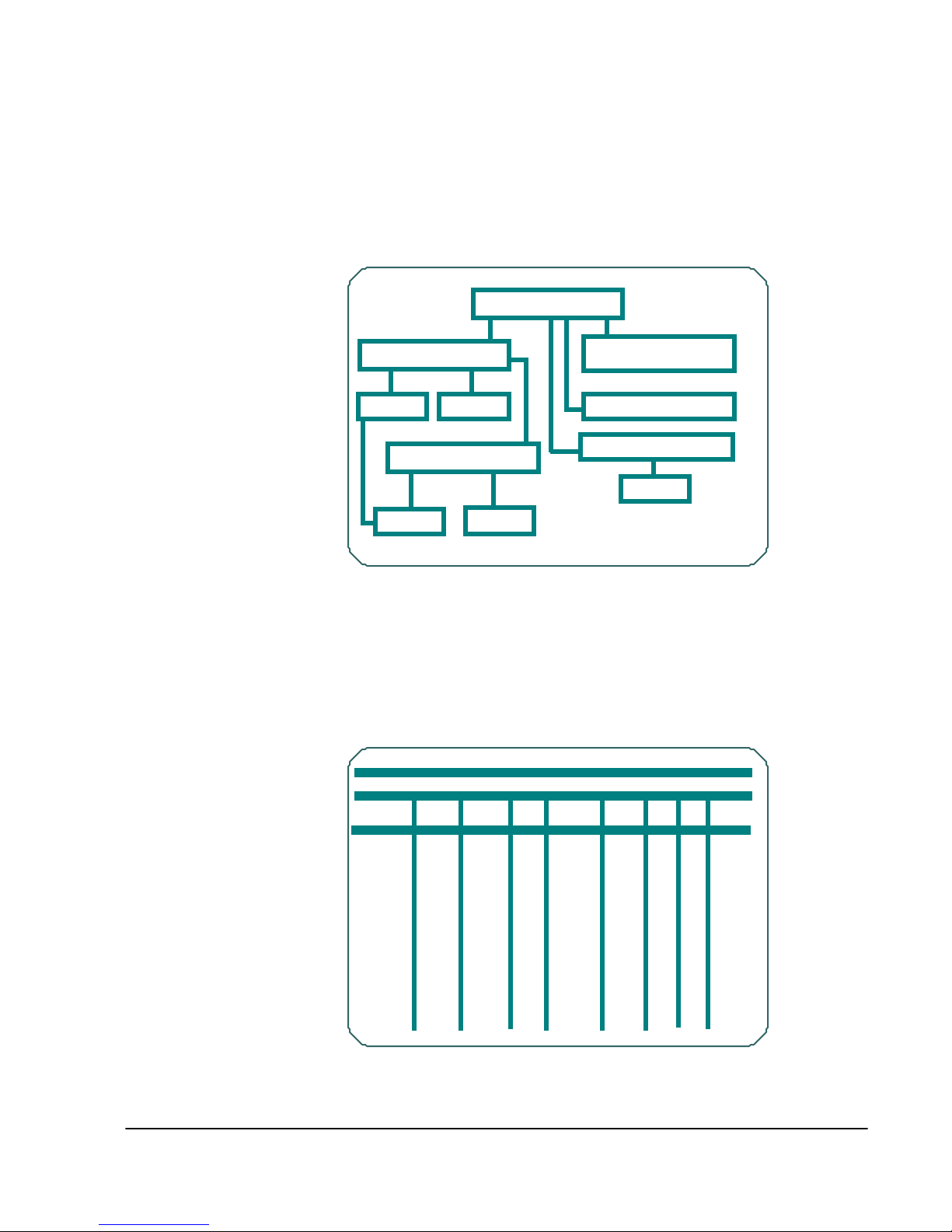
– wi ll dis pl a y a "ro ad map " of the pa n e ls (sc reens ), sh ow n in
Fi gure 2.
– will exit to the NCCF (NetView Controls Command Facility) .
– will scroll the scr e en up or down if there is more
information to display.
– will re- display the screen with updated values.
2 NetV iew Service Poin t
Page 7
Help Panel
Moving the cursor to an entry under
[PF4] (Ln_Status
) will display a line status scr een for that service point, as described
under "Line Status Panel."
Main Status Panel
Service Point Name
( in F igure 1) and pr es s i ng
Line Status Panel
Line S tatus Pan el
Line Stats Line Config
PU Status Panel
PD Stats
PU Co nf i g
Ha r dwa re Config Pan e l
RT and SY S L OGs
Frame Relay
FR C o nfi g
Figure 2 On-Line Help Panel
Service Point: BD0NV SP SDLC Line Status Panel Version: 3200
PF 1-Help 2-Exit 3-End 4-PU Status 5-Line Stats 6-Config 7-Act 8-Dea ct 10-Disp
Line Actual Desired
Name Status Status Port Interface DTR DSR CTS DCD
LINE11 AC TIV ACTIV 0/0 RL P/960 ON ON ON OFF
LINE12 AC TIV ACTIV 0/1 RL P/960 ON ON ON ON
Supplemental Software User Guide 3
F igur e 3 L ine St atus Panel
Page 8

D at a Disp layed
Li ne Na m e
– is the Name configured on the first screen of the Cab letron device S NA
Port record, or if that parameter is not config ured, the Name in the NetView Parameters part of the Network Defaults record.
Actual Status
Desired Status
– is the cu rrent status (active or inactive) of the line.
– mat ches the Blo cked Port Flag (N = activ e, Y = inactiv e) config ure d
on the first screen of the SNA Port reco rd.
– i s t he R LP an d port that defines the li ne.
Port
Interface
DTR/DSR/CTS/DCD
– is alwa ys
Function Key Operations
Pressing one of the fu nction keys listed below will per form the appropriate operation
fr om the Li ne St at us panel :
[PF1] Help
[PF3] End
Moving the cursor to an entry under Line Name and pressing a supported function key
gives you these additional options:
[PF4] PU_Status
under "P U S tat us P ane l " lat er.
RLP/960
.
– a re the cur rent states (On, Off) of the modem sign als on the line.
– will display the Help panel (Figure 2).
– w ill return yo u to the M ain Statu s pan el (Figure 1).
– w ill display th e PU Status panel for that line, as describ ed
[PF6] Config
to change the values of some parameters. See "Line Configuration
Panel" later.
[PF7] Act
[PF8] Deact
– will activate the line.
– will displa y a sc reen of parameter s for that line, and allo w you
– will de-activate the line.
4 NetV iew Service Poin t
Page 9

PU Status Panel
Service Point: BD0NV SP PU S tatus Pan el Version: 3200|
Line name: LIN E4
PF 1-Help 2-Exit 3-End 4-PU Stats 6-C onfig 7-Act 8-Deact 10-Display 11-Refresh
SDLC LLC2
PU Actual Desired POLL Ac tual LANCON
Name Status Status ADDR Statu s Status MAC A ddress XID
PUC3 ACTI V ACTIV C3 ACTIV AC TIV FF FFFFFF DCE3 00DCE301
Figure 4 PU Status Panel
Da t a Disp layed
PU Name
SDLC Actual Status
Desired Status
screen of the SNA Port record.
PO LL AD DR
of the SNA Port record.
LLC2 Actual Status
LANCON Status
with Netlink's SDLC Link Server.)
MA C Addr es s
of the SNA Port record.
XID
– is the PU Name co nfigured in the Cabletron device SNA Port record.
– is the Istatus (active or inactive) configured on the PU parame ters
– is the Lo cal SAP Address configured on the LLC2 Parameters screen
– is the Lo cal MAC Addr ess conf igu red on the LLC2 Paramete rs scr een
– is the ID created fro m IDBLK and IDNUM in the SNA Port record.
Function Key Operations
Pressing one of the function keys listed below will perform the appropriate operation
from the PU Status panel:
[PF1] Help
– is the current status (active or inactive) of the PU.
– is the current status (active or inactive) of the LLC2 session.
– is not app lic a ble. (Th is is from part of the software that is shar e d
– w ill display the Help panel (Figure 2).
[PF3] End
Supplemental Software User Guide 5
– will return you to the Line Sta tus panel (Figure 3).
Page 10

Mo ving the curs or to a n ent ry under P U Name and pressing a suppor ted funct ion key
gives you these additional options:
[PF6] Config
[PF7] Act
[PF8] Deact
Line C onfigurati on Panel
Service Point: BD0NVSP SDLC Line Configuration P anel Version: 3200|
Line name: LIN E11
Actual Status: AC TIV
Desire d Status : ACTIV
PF 1-Help 2-Exit 3-End 4-PU Stats 6-C onfig 7-Act 8-Deact 10-Display 11-Refresh
ISTATU S ACT ACTI VTO 10
NRZI NO RCVCLO CK DTE
CLOCK EXTERNAL PAUSE 40
SPEED 9600 RETR IES 5
MAXIN 7 LPDATYPE 2
MAXOUT 7 LINKROLE PRIMARY
MO DULO 8
– will displa y a sc reen of parameter s for that line, and allo w you
to change the values of some parameters. See "Line Configuration
Panel" later.
– will activate the line.
– will de-activate the line.
F igur e 5 Line C onfigur ation Pa nel
Configurable Parameters
ISTATUS
will caus e the line to be enabled (if
undergoes IPL. The line will remain in that state until either an on-line port disable or
enabl e is perform ed on the Cabletron device (as described in the User Guide) or a
NRZI
VARY IN ACT
or
VARY ACT
is sent f rom the NetVIEW manager.
is the inverse of the parameter NRZ in the SNA Port record in the Cabletron device.
The setting determine s the level of data encoding:
= NRZ, wh ich means that 1 r epres ents high -lev el e ncodin g and 0 is low-level.
No
= NRZI, which means that 1 rep resents no change in level and 0 is a change.
Yes
CLOCK
is equivalent t o the C abletron de vi ce parameter
whether the port will generate the clock necessary to synchronize traf fic ove r the link.
INTERNAL
6 NetV iew Service Poin t
= Yes,
EXTERNAL
= No.
) or disabled (if
ACT
INACT
Generate Clock
) the next time the node
, which speci fies
Page 11

SPEED
is th e line speed. Valid line speeds are:
ACTIVTO
is the activity timer (Ti).
RCVCLOCK
is equivalent to the Cabletron device parameter
the clock to be looped back from th e D TE using the term inal timi ng signal. Valid
valu es are
PAUSE
is eq ui v a le nt to t he C abl et ron de vi ce paramet er
between poll s by the Cabletron device TPA D of its PU when the PU has no data to
send. Valid values are
75 150 300 600 1200
2400 4800 9600 14.4K 19.2K
24K 28.8K 38.4K 48K 56K
64K 72K 112K 128K 168K
192K 224K 256K 280K 320K
336K 384K 392K 448K 504K
512K 560K 576K 616K 640K
672K 704K 728K 768K 784K
832K 840K 896K 952K 960K
1.008M 1.024M 1.064M 1.088M 1.12M
1.152M 1.176M 1.216M 1.232M 1.28M
1.288M 1.344M 1.4M 1.408M 1.456M
1.472M 1.512M 1.536M 1.568M 1.6M
1.624M 1.664M 1.668M 1.728M 1.792M
1.856M 1.92M 1.984M 2.048M
, which allows
, which is the time
and N.
Y
(milliseconds).
0-125
Rcv Clock (TT) from DTE
No Data Poll Period
RETRIES
is equivalent to th e Cabletron d evice par ameter
the maximum numb er of times the SNA port will attempt to se nd a frame after expiration of the
LPDATYPE
No Response Poll Period
spec ifies the version of LPDA (1 or 2) that will be used.
Function Key Operations
Pressing one of the function keys listed below will perform the appropriate operation
from the Line Configuration panel:
[PF1] Help
[PF2] Exit
[PF3] End
up date th e Ca bl et ron de vi ce d a ta base v a l ues . After yo u s el e ct
you will be r e turned to the M ain Statu s pan el (Figure 1).
Maximum Retransmissions
. Valid values are
1-99
.
, which is
– w ill display the Help panel (Figure 2).
– w ill return you to the Line Status panel (Figure 3).
– will ask whether you want to commit the change s, which will
or No,
Yes
Supplemental Software User Guide 7
Page 12

M oving the curs or to a paramet er and pres si ng a s upported func t ion key gi ves you
these additional options:
[PF6] Modify
[PF7] Activate
[PF8] Deact
[PF10] Disp lay
[PF11] Refr esh
PU Configur ation Panel
Service Point: BD0NVSP PU Lin e Configurati on Panel Vers ion: 3200|
Line name: LIN E11 PU Name: P UC3
Actual Status: AC TIV Desir ed S tatus: ACTIV
PF 1-Help 2-Exit 3-End 4-PD Stats 6-Modify 7-Act 8-Deac t 10-Display 11-Refr esh
SDLC Address C3 Response Time r (T1) 10
I STATUS ACTIV Ack Timer (T2) 100
MAXDATA 265 Inactivity Timer (Ti) 30
MAX OUT Se e Line Con fig LANI N (N3) 001
MO DUL O Se e Li ne Con f ig LANO UT ( Tw) 001
DATMODE HALF retries (N2) 008
REPLYTO 1.0 Bandwidth Allocation (BAG) 00
R E TRIE S Se e Li ne Con f ig
LP DS RESI D 80
A UT O CAL L E NABL E Lo cal SAP 04
Auto Retry Tout 60 Local MAC Address 4000000000C3
Auto Retry Ct 00 PU Type LLC 2
Local S ub 1123
Remote Sub 2223
– will allow yo u to change the configure d values of the
parameter, if the parameter is display ed in gr e en.
– will activate the line.
– will de-act ivate the line.
– will display output from the r uncmd.
– wil l re-display the screen with update d values.
SDLC LLC2
Figure 6 PU Configura tion Panel
Configurable Parameters
IST ATUS
will cause the PU to be enabled ( if
is activated. T he PU will remain in that state until either an on-line SDLC PU disable
or enable is perform ed on the Cabletron device (as described in t he User Guide) or a
VARY IN ACT
MAXDATA
or
VARY ACT
is sent from the NetVIEW manager.
is equivalent to the Cabletron device parameter
valu es are
REPLYTO
25-4105
.
is equivalent to the Cabletron device parameter
between polls by the TPAD port of its PU when the PU is not responding. The TPAD
will continue to poll at this interval up to the number of times specified by
8 NetV iew Service Poin t
) or disabled (if
ACT
) the next time the line
INACT
Maximum Bytes per Frame
No Resp Poll Period
, which is the time
. Va lid
RETRIES
Page 13

(Cabletron device parameter
(milliseconds).
LPDARESID
is the LPDA Resource ID, which d efin es LUs on the PU. The v a lue m ust match the
LOCADDR defined on VTAM. Valid values are
AUTOCALL
caus es auto matic calling between SNA ports when the controlle r becom e s active. Th e
valid val ue s are
Aut o Ret r y Tout
is equivalent to the Ca bletron devi ce paramet er
between autocall retries. Valid v alu es are 15-255 (seconds).
Auto Retry Ct
is equivalent to th e Cabletron d evice par ameter
maxim um number of tim e s an autocall will be sent. Valid values are
a valu e of
Local S ub
is th e subscriber ad dress of the local (to the Cabletron device) end of an SNA connection.
Remote Sub
is th e address of the remo te (to the Cabletron device) end of an SNA connection.
Maximum Retransmissions
ENABLE
allows indefinit e retries .
0
and
DISABLE
). Valid valu es are
.
0-255
40-9999
.
Autocall Retry Time
Autocall Retry Count
, which is the time
, which is the
. Note that
0-255
Response Ti mer (T1 )
is used to detect the failure to receive a required acknowledgment or resp onse from
the remote link station . The valid values are
station will start the timer when it transmits one of these:
●
an Information LPDU.
●
a Command LPDU with the P bit set to B'1.' (If this LPDU is sent while the timer
is already running, the link station will reset and restart it.)
The link statio n will reset T1 when it receives one of these:
●
A REJ LPDU, provided a Command L PDU with P bit set to B'1' is not outstanding.
●
A Respons e LPDU with the F bit s et to B '1.'
●
An Information or Supervisory LPDU with an N(R) greater than the last N(R)
received and less than or equ al to the line station's V(S), provided a Command
LPDU with P bit set to B'1' is not outstanding.
If additional LPDUs are set from the remote link station after the local station has reset
T1, the timer will be restarted if acknowledgments of or responses to those LPDUs are
outstandin g. If no acknowledg men ts/re spons es are outstanding, the link station will
start the inactivity time r. (See "Ti" later.)
If T1 expires and acknowledgme nts /responses ar e still outsta nding , the link station
will send one of the following, then restart T1:
(x 100 milliseconds).The link
0-250
●
Supplemental Software User Guide 9
A Su per visory LPDU with the P bit s et to B'1,' to so lic it rem ote lin k station
status.
Page 14

●
An y Unnumbered LPDUs that wer e not responded to the first time they were
sent.
If a cknowledgments/response s are still outstanding after N2 tries (see that entry), the
link station will decla re the link inoperative.
Ack Timer (T2)
is used by the link station to delay sending an acknowledgment o f a received Information LPDU. Valid values are
The timer is started wh en the LPDU is received and reset when the acknowledgment
is sent. If the timer expires before the acknowledgment is sent, it must be sent as soon
as possible.
Inactivity Timer (Ti)
is used by the link station to detect an inoperative conditi on in either th e rem ote link
station or the transmission medium. Vali d values are
The timer will be sta rted if T1 has been reset (for one of the reasons listed under "T1"
earlier), and additional LPDUs have been sent by the remote link station, and there are
no o uts ta nding acknowle dg ment s or re sp on ses from th e local link station.
If the local station does not receive an LPDU before Ti expires, th e station must send
an LPDU with the P bit set to B '1' to solicit the re mote station's status. Recovery then
proceeds as described under "T1 " earlier.
100-5000
(millis econds).
1-50
(seconds).
LANIN (N3)
is the number of Information LPDUs that will be received befo re sending an ackn owledgment. Valid values are
This par a meter is us ed in conjunction with T2 to allow stati ons to reduce traffic. A
counter is initialize d to N3, and will be dec r e men te d by one each tim e a valid
sequential Informati on LPDU is received . When the counter reaches
edgm en t is sent.
N3 is res et wh enever an Inform ation or Supervisory acknowled gmen t LPDU is sent
by th e local statio n.
LANOUT (Tw)
is the max imum number of sequentially numbered Inform ation LPDUs that the link
station can have outstanding . Valid values are
Ret r ie s (N 2)
is the maximum number of times that an LPDU (including Information LPDUs resent
after a checkpoint operation) will be sent following expiration of T1. Valid values are
.
0-255
Ban dwidt h Allocati o n (BAG)
assigns the host to one of sixteen groups whose parameters regulate bandwidth usage.
See " Band width Allocatio n Groups " in the C abletr on devi ce User Gu ide. Val id values
ar e
0-16
.
1-127
.
an a ckn ow l -
0
.
1-127
Local SA P
is the rem ote SAP address used to connect the PU to the host. This parameter is relevant only in a connection to a 317 4 or AS/400-ty pe setup where a specific source
10 NetV iew Service Poin t
Page 15

SAP addres s is required. If the LLC2 session wi ll be run over a native LLC2 frame
rela y interface, the parameter will be ignored.
Local MAC Address
identif ie s the PU to the host. Like the local SA P add ress, this parameter is releva nt
only in a connection to a 3174 or AS/400-type setup where a specific sourc e MAC
addr ess is required. If the LLC2 session will be run over a native LLC2 frame relay
interface, the paramet er will be ignore d.
PU Typ e
is SDLC or LLC 2.
Function Key Operations
Pressing one of the function keys listed below will perform the appropriate operation
from the PU Status panel:
[PF1] Help
[PF2] Exit
[PF3] End
– w ill display the Help panel (Figure 2).
– w ill retu rn you to the PU Status panel (Figu re 4 ).
– will ask whether you want to commit the change s, which will
up date th e Ca bl et ron de vi ce d a ta base v a l ues . After yo u s el e ct
Yes
or No,
you will be r e turned to the M ain Statu s pan el (Figure 1).
M oving the curs or to a paramet er and pres si ng a supported functi on ke y gives you
these additional options:
[PF6] Modify
– will allow you to change the configure d values of the
param eter, if the paramet er is displayed in green.
[PF7] Act
[PF8] Deact
[PF10] Display
[PF11] Refresh
– will activate the line.
– will de-activate the line.
– will display output from the r uncmd.
– w ill re-display the sc reen with updated values.
Supplemental Software User Guide 11
Page 16

Alerts
The Cabletron device will issue alerts (events) based upon NMVT protocols. The node
transparently passes all Alerts (Basic, Gen eric, RECFMS, etc. ) received from downstre am S NA /S DLC devi ce s.
Host Alert ID Number
Each Alert generated by the Cabletron nod e appears in the event log identified by a
Netlink event number. The Alert is identified to the host console by an Alert ID
number. The following table cross-references each Alert ID number to the corresponding event num ber that is us ed in this appendix .
Alert ID Num ber
X’0 39 6D7 BA’ 718 X'6279ADDE’ 721
X’0AECC2A6’ 713 X’6E0781DD’ 717
X’0E2DDF11’ 712 X’7F15E253’ 724
X’1103D152’ 709 X’83D91642’ 741
X’15C2CCE5’ 708 X’87180BF5’ 742
X’1C40F78B’ 710 X’8A5B2D2C’ 739
X’1D1B6697’ 722 X’8E9A309B’ 740
X’216 D 1033’ 745 X ’A 472 B C48’ 71 4
X’2 5AC 0D84’ 746 X’B1D9A4C5’ 737
X’28EF2B5D’ 743 X’B3B7D723’ 705
X’2C2E36EA’ 744 X’B776CA94’ 704
X’32A37F1B’ 701 X’BA35EC4D’ 707
X’3 2E5 16A1’ 761 X’B D84C4C9’ 702
X’34FFCB87’ 720 X’BEF4F1FA’ 706
X’3DCB0D63’ 715 X’C08037D8’ 759
X’480F6C65’ 762 X’E65B0B7F’ 738
X’548CB735’ 723 X’EABB6A14’ 711
X’5A44BB82’ 760 X’EE849C82’ 725
X’5B8F5BA7’ 736
Event Num ber Aler t ID Number Eve n t Number
12 NetV iew Service Poin t
Page 17

Alerts
701
Event Log Message puname /linename – SDLC Link Stn Not Responding
Host Co nsole Me ss age LINK ERROR:SDL C COMMUNICATION S/ REMOTE NODE
A ler t Conditi on An SDLC logical link has bee n l ost. The secondary link station does
not respond to poll frames s ent by the pr i mary s ta ti on.
Alert ID Number X'32A37F1B’
A ler t Type X'01’ Permanent
Alert Des cri ption X'3300’ Link Error
Pr obable Caus es X'210 4'
X'2 031’
Us er Ca u se s X' 0 209 ’ R emo t e devi ce p ow er of f
A ctions X'020 0’ Check power
Install Caus es (n one)
Failure Causes
A ctions (Sen der-specific acti ons)
A dditional SV s X'52'S V
X'2 104'
X'3 511'
X'F017’
X’02'S F
X’04'S F
X'06'SF
X'07'SF
X'8C'S V
X’01'S F
X'02'SF
X'03'SF
X'04'SF
X'05'SF
X'06'SF
X'07'SF
X'08'SF
X'05'SV
X'10'SF
SDLC co mmunications/re m ote node
Line
SDLC co mmunications/re m ote node
Line
Poll count exhausted
LCS Configuration
Remote Device Address
Local Device Address
Link Sta tion Attribute s
Link Attributes
Link Sta tion Data
Curr ent Ns /Nr Counts
Outs ta nding Frame Count
Last Co ntrol Field Received
Last Co ntrol Field Sent
Sequence Number Modulus
Link Sta tion Stat e
LLC Repl y Timer Expirati on Count
Last Received Nr Count
Hier archy/Resource Li st
Hierarchy Name List
First reso ur ce below sender:
R es o urc e Na m e = ( L I N E NA M E)
Resource Type = X'3D'(LI NE )
Second r es our ce below send er:
Resource Name = (Physic al Unit Name)
Resource Type = X '80'(Physical Unit)
Supplemental Software User Guide 13
Page 18

702
Event Log Me ssage puname/line name – SDLC Li nk Stn S ent DM
Hos t Con sole Me ssage LINK ERROR:SDLC COMMUNI CATIONS
Alert Co ndi ti on An SDLC lo gical link ha s been lost. The seconda ry l ink st ation sen t a
Disconnect Mode response to the primary st ation.
Alert I D Nu m b er X'BD84 C4C9’
Alert T ype X'01’ Permanent
Aler t D escri ption X'3300’ Link Err or
Probable Ca uses X'2004' SDLC communic ations
User Ca uses (none)
Insta ll Ca uses (none)
Failure Ca uses X '2004'
X'F01A’
Actions ( Sender-spec i fi c actions )
Additional SVs X'52'SV
X’02'SF
X’04'SF
X'06'SF
X'07'SF
X'8C'SV
X’01'SF
X'02'SF
X'03'SF
X'04'SF
X'05'SF
X'06'SF
X'07'SF
X'08'SF
X'05'SV
X'10'SF
SDLC c om m unications
DM received
LC S Conf i gur ation
Re m o te Devi ce Ad dress
Local Device Address
Link St ation At tributes
Link Attributes
Link St ation Data
Cu rre nt Ns / Nr Counts
Outs ta nding Frame Count
Last Contro l Fie ld Rec eived
Last Contro l Fie ld Sen t
Sequence Numb er Modulus
Link St ation State
LLC Reply Time r Expi r ation C ount
La st Received Nr Count
Hierarchy/Re source List
Hierarchy Name List
First resource below sender:
Re source Name = (LI NE NAME)
Resource Type = X'3D'(LINE )
Second r esource below sender:
Resource Name = (Physical Unit Name)
Resource Type = X'80'(Physical Unit)
14 NetV iew Service Poin t
Page 19

704
Event Log Me ssage puname/line name – SDLC Li nk Stn rcvd FRMR - Inv . cmd
Hos t Con sole Me ssage SOFTWARE PROGR AM ERROR:SD LC COMMU NICA T IONS
Alert Condi ti on An SDLC l ogi ca l link ha s been lost. The prim ary link station sent an inv ali d or unsup-
ported command to the se condar y li nk s ta ti on. The s econdary link station responded
w i th a F rame r eje ct .
Alert ID Numb er X'B776CA94 ’
A l e r t Ty pe X' 0 1 ’ P er m a nen t
A le r t Desc r ip t io n X ' 21 00’ So f twa r e Pro g ram Err or
X'2004'
Pro ba bl e Causes
User Ca uses (none)
Inst all Causes (none )
Fai lure Causes X'1000'
Actions ( Sender-spec i fi c action s)
Addition al SVs X'52' SV
X'1000'
X'F010’
X’02'SF
X’04'SF
X'06'SF
X'07'SF
X'8C'SV
X’01'SF
X'02'SF
X'03'SF
X'04'SF
X'05'SF
X'06'SF
X'07'SF
X'08'SF
X'05'SV
X'10'SF
SDLC communicat ions
Software program
Software program
Fra m e reject rec eived: i nval id/uns uppor ted command or r esponse sent
LC S Configuration
Remote Device Addres s
Loc al D evi ce Ad dr e ss
Link St at ion Attributes
Link Attrib utes
Link S ta ti on Data
C ur rent Ns / Nr Counts
Outstanding Frame Count
Last Control Field Received
Last Contr ol Fie ld Sent
Sequence Numbe r Modul us
Link S ta ti on State
LLC Reply Timer Expi r atio n Count
Last Re ceived Nr Count
Hierarchy/Re source List
Hierarchy Name List
First resource below sen der:
Resour ce Nam e = (LINE NAME)
R es our ce Type = X'3D'(LIN E)
Second resource b elow sender:
Resource Name = (Physical Unit Name)
Resource Type = X'80'(Physical Unit)
Supplemental Software User Guide 15
Page 20

705
Event Log Messa ge puname/lin ena m e – SDLC Stn rcvd FRMR - IFLD Invalid
Host Co nsol e M es sage SOFTWARE PROG RAM ERROR:SDLC COMMUNICATIONS
Ale r t Conditi on An SDLC logical link has been lost. The pri mary li nk station sent an i-fiel d when not per-
mitte d to the secondary link station. The s econdary link stat ion r es ponded with a Frame
reject.
Alert ID Number X'B3B7D723’
Ale r t Type X'01’ Permanent
Alert De scription X'2100’ Softwar e Program Error
X'2004'
Pr obable Causes
User Causes (none)
Install Causes (none)
Failure Causes X'1000'
A ct io ns ( Se n de r- sp ec if i c act io ns)
Ad ditional SVs X'52'SV
X'1000'
X'F011’
X’02'S F
X’04'S F
X'06'SF
X'07'SF
X'8C'S V
X’01'S F
X'02'SF
X'03'SF
X'04'SF
X'05'SF
X'06'SF
X'07'SF
X'08'SF
X'05'SV
X'10'SF
SDLC communicati ons
Software progr am
Software progr am
Frame reject receive d: i-field sent when not permitted
LCS Configuration
Remote Devi ce Address
Lo cal D evice Address
Link Sta tion Attribute s
Link Attributes
Link Sta tion Data
Curr ent Ns/Nr Counts
Outsta ndi ng Frame Count
Last Control Field Recei ved
Last Con trol Fiel d Sent
Sequence Number M odul us
Link Sta tion St ate
LLC Repl y Timer E xpir ation Count
Last Recei ve d Nr Count
Hier archy/Resource List
Hier archy Na me List
Fir st resource below sen der:
Re sour ce Nam e = (LINE NAME)
Resourc e Type = X'3D' (LI NE )
Second r es our ce below sender:
Res ource Name = (Physical Unit Na me)
Re sourc e Type = X '80'(Physical Unit)
16 NetV iew Service Poin t
Page 21

706
Event Log Me ssage puname/line name – SDLC S tn rcv d FRMR - Nr In valid
Hos t Con sole Me ssage SOFTWARE PROGR AM ERROR:SD LC COMMU NICA T IONS
Alert Condi ti on An SDLC l ogi ca l link has been lost. The prima ry l ink st at ion sent a frame with an inva lid
N(r). The se condary link s ta ti on r esponded with a Frame rejec t.
Alert ID Number X'BEF4F1FA ’
A l e r t Ty pe X' 0 1 ’ P er m a nen t
A le r t Desc r ip t io n X ' 21 00’ So f twa r e Pro g ram Err or
X'2004'
Pro ba bl e Causes
User Ca uses (none)
Inst all Causes (none )
Fai lure Causes X'1000'
Actions ( Sender-spec i fi c action s)
Addition al SVs X'52' SV
X'1000'
X'F012’
X’02'SF
X’04'SF
X'06'SF
X'07'SF
X'8C'SV
X’01'SF
X'02'SF
X'03'SF
X'04'SF
X'05'SF
X'06'SF
X'07'SF
X'08'SF
X'05'SV
X'10'SF
SDLC communicat ions
Software program
Software program
Frame rej ect r eceived: invalid N(r) sent
LC S Configuration
Remote Device Addres s
Loc al D evi ce Ad dr e ss
Link St at ion Attributes
Link Attrib utes
Link S ta ti on Data
C ur rent Ns / Nr Counts
Outstanding Frame Count
Last Control Field Received
Last Contr ol Fie ld Sent
Sequence Numbe r Modul us
Link S ta ti on State
LLC Reply Timer Expi r atio n Count
Last Re ceived Nr Count
Hierarchy/Re source List
Hierarchy Name List
First resource below sen der:
Resour ce Nam e = (LINE NAME)
R es our ce Type = X'3D'(LIN E)
Second resource b elow sender:
Resource Name = (Physical Unit Name)
Resource Type = X'80'(Physical Unit)
Supplemental Software User Guide 17
Page 22

707
Event Log Messa ge puname/lin ena m e – SDLC Stn rcvd FRMR - Ifld too long
Host Co nsol e M es sage SOFTWARE PROG RAM ERROR:SDLC COMMUNICATIONS
Ale r t Conditi on An SDLC logical link has bee n lo st. The pr ima r y li nk stat i on se nt a fram e wi th a n i- field
that was too l ong. The secondary link sta tion r es ponded with a Frame rej ect.
Alert ID Number X'BA35E C4D’
Ale r t Type X'01’ Permanent
Alert De scription X'2100’ Softwar e Program Error
X'2004'
Pr obable Causes
User Causes (none)
Install Causes (none)
Failure Causes X'1000'
A ct io ns ( Se n de r- sp ec if i c act io ns)
Ad ditional SVs X'52'SV
X'1000'
X'F013’
X’02'S F
X’04'S F
X'06'SF
X'07'SF
X'8C'S V
X’01'S F
X'02'SF
X'03'SF
X'04'SF
X'05'SF
X'06'SF
X'07'SF
X'08'SF
X'05'SV
X'10'SF
SDLC communicati ons
Software progr am
Software progr am
Frame reject receive d: Max imum I -field length exceeded
LCS Configuration
Remote Devi ce Address
Lo cal D evice Address
Link Sta tion Attribute s
Link Attributes
Link Sta tion Data
Curr ent Ns/Nr Counts
Outsta ndi ng Frame Count
Last Control Field Recei ved
Last Con trol Fiel d Sent
Sequence Number M odul us
Link Sta tion St ate
LLC Repl y Timer E xpir ation Count
Last Recei ve d Nr Count
Hier archy/Resource List
Hier archy Na me List
Fir st resource below sen der:
Re sour ce Nam e = (LINE NAME)
Resourc e Type = X'3D' (LI NE )
Second r es our ce below sender:
Res ource Name = (Physical Unit Na me)
Re sourc e Type = X '80'(Physical Unit)
18 NetV iew Service Poin t
Page 23

708
Event Log Me ssage puname/line name – SDLC Re m Stn sen t Invalid Comm and
Hos t Con sole Me ssage SOFTWARE PROGR AM ERROR:SD LC COMMU NICA T IONS
Alert Condi ti on An SDLC l ogi ca l link has bee n lo st. The se condary link station s ent an invalid or unsup-
ported command to the primar y link station.
Alert ID Numb er X'15C2CCE5 ’
A l e r t Ty pe X' 0 1 ’ P er m a nen t
A le r t Desc r ip t io n X ' 21 00’ So f twa r e Pro g ram Err or
Probable Ca uses X'2004'
X'1023'
User Ca uses (none)
Inst all Causes (none )
Fai lure Causes X'1023'
X'F020’
Actions ( Sender-spec i fi c action s)
Addition al SVs X'52' SV
X’02'SF
X’04'SF
X'06'SF
X'07'SF
X'8C'SV
X’01'SF
X'02'SF
X'03'SF
X'04'SF
X'05'SF
X'06'SF
X'07'SF
X'08'SF
X'05'SV
X'10'SF
SDLC communicat ions
C om m unications pr ogr am - remote
C om m unications pr ogr am in remote node
Inval id /unsupported com mand or r esponse received
LC S Configuration
Remote Device Addres s
Loc al D evi ce Ad dr e ss
Link St at ion Attributes
Link Attrib utes
Link S ta ti on Data
C ur rent Ns / Nr Counts
Outstanding Frame Count
Last Control Field Received
Last Contr ol Fie ld Sent
Sequence Numbe r Modul us
Link S ta ti on State
LLC Reply Timer Expi r atio n Count
Last Re ceived Nr Count
Hierarchy/Re source List
Hierarchy Name List
First resource below sen der:
Resour ce Nam e = (LINE NAME)
R es our ce Type = X'3D'(LIN E)
Second resource b elow sender:
Resource Name = (Physical Unit Name)
Resource Type = X'80'(Physical Unit)
Supplemental Software User Guide 19
Page 24

709
Event Log Messa ge puname/lin ena m e – SDLC Rem Stn sent unexpecte d IFLD
Host Co nsol e M es sage SOFTWARE PROG RAM ERROR:SDLC COMMUNICATIONS
Ale r t Conditi on An SDLC logical link has bee n lo st. The se condary link station se nt a n I- field w hen n ot
permitted to the primary link station.
Alert ID Number X'15C2CCE5’
Ale r t Type X'01’ Permanent
Alert De scription X'2100’ Softwar e Program Error
X'2004'
Pr obable Causes
User Causes (none)
Install Causes (none)
Failure Causes X'1023'
A ct io ns ( Se n de r- sp ec if i c act io ns)
Ad ditional SVs X'52'SV
X'1023'
X'F021’
X’02'S F
X’04'S F
X'06'SF
X'07'SF
X'8C'S V
X’01'S F
X'02'SF
X'03'SF
X'04'SF
X'05'SF
X'06'SF
X'07'SF
X'08'SF
X'05'SV
X'10'SF
SDLC communicati ons
Communications program - remote
Communi cations pr ogr am in remote node
I-field received when not pe r m it te d
LCS Configuration
Remote Devi ce Address
Lo cal D evice Address
Link Sta tion Attribute s
Link Attributes
Link Sta tion Data
Curr ent Ns/Nr Counts
Outsta ndi ng Frame Count
Last Control Field Recei ved
Last Con trol Fiel d Sent
Sequence Number M odul us
Link Sta tion St ate
LLC Repl y Timer E xpir ation Count
Last Recei ve d Nr Count
Hier archy/Resource List
Hier archy Na me List
Fir st resource below sen der:
Re sour ce Nam e = (LINE NAME)
Resourc e Type = X'3D' (LI NE )
Second r es our ce below sender:
Res ource Name = (Physical Unit Na me)
Re sourc e Type = X '80'(Physical Unit)
20 NetV iew Service Poin t
Page 25

710
Event Log Me ssage puname/line name – SDLC Re m Stn sen t Invalid Nr
Hos t Con sole Me ssage SOFTWARE PROGR AM ERROR:SD LC COMMU NICA T IONS
Alert Condi ti on An SDLC l ogi ca l link ha s been lost. The sec ondary link stat io n se nt a frame wi th an
invalid N(r).
Alert ID Number X'1C40F78B’
A l e r t Ty pe X' 0 1 ’ P er m a nen t
A le r t Desc r ip t io n X ' 21 00’ So f twa r e Pro g ram Err or
X'2004'
Pro ba bl e Causes
User Ca uses (none)
Inst all Causes (none )
Fai lure Causes X'1023'
Actions ( Sender-spec i fi c action s)
Addition al SVs X'52' SV
X'1023'
X'F022’
X’02'SF
X’04'SF
X'06'SF
X'07'SF
X'8C'SV
X’01'SF
X'02'SF
X'03'SF
X'04'SF
X'05'SF
X'06'SF
X'07'SF
X'08'SF
X'05'SV
X'10'SF
SDLC communicat ions
C om m unications pr ogr am - remote
C om m unications pr ogr am in remote node
Invalid N(r) received
LC S Configuration
Remote Device Addres s
Loc al D evi ce Ad dr e ss
Link St at ion Attributes
Link Attrib utes
Link S ta ti on Data
C ur rent Ns / Nr Counts
Outstanding Frame Count
Last Control Field Received
Last Contr ol Fie ld Sent
Sequence Numbe r Modul us
Link S ta ti on State
LLC Reply Timer Expi r atio n Count
Last Re ceived Nr Count
Hierarchy/Re source List
Hierarchy Name List
First resource below sen der:
Resour ce Nam e = (LINE NAME)
R es our ce Type = X'3D'(LIN E)
Second resource b elow sender:
Resource Name = (Physical Unit Name)
Resource Type = X'80'(Physical Unit)
Supplemental Software User Guide 21
Page 26

711
Event Log Messa ge puname/lin ena m e – SDLC Rem Stn Exceeded window size
Host Co nsol e M es sage SOFTWARE PROG RAM ERROR:SDLC COMMUNICATIONS
Ale r t Conditi on An SDLC logical link has bee n lo st. The num ber of I-fr ames tra nsmitted by the r emote
link station has exceeded the local link station's rece ive window size .
Alert ID Number X'EABB6A1 4’
Ale r t Type X'01’ Permanent
Alert De scription X'2100’ Softwar e Program Error
Pr obable Causes X'2004'
X'1023'
User Causes (none)
Install Causes (none)
Failure Causes X'1023'
X'F01B’
A ct io ns ( Se n de r- sp ec if i c act io ns)
Ad ditional SVs X'52'SV
X’02'S F
X’04'S F
X'06'SF
X'07'SF
X'8C'S V
X’01'S F
X'02'SF
X'03'SF
X'04'SF
X'05'SF
X'06'SF
X'07'SF
X'08'SF
X'05'SV
X'10'SF
SDLC communicati ons
Communications program - remote
Communi cations pr ogr am in remote node
Receive wi ndow size ex ce eded
LCS Configuration
Remote Devi ce Address
Lo cal D evice Address
Link Sta tion Attribute s
Link Attributes
Link Sta tion Data
Curr ent Ns/Nr Counts
Outsta ndi ng Frame Count
Last Control Field Recei ved
Last Con trol Fiel d Sent
Sequence Number M odul us
Link Sta tion St ate
LLC Repl y Timer E xpir ation Count
Last Recei ve d Nr Count
Hier archy/Resource List
Hier archy Na me List
Fir st resource below sen der:
Re sour ce Nam e = (LINE NAME)
Resourc e Type = X'3D' (LI NE )
Second r es our ce below sender:
Res ource Name = (Physical Unit Na me)
Re sourc e Type = X '80'(Physical Unit)
22 NetV iew Service Poin t
Page 27

712
Event Log Me ssage puname/line name – SDLC S tat i on Inactivity tim er e xp
Hos t Con sole Me ssage LINK ERROR:SDLC COMMUNICATIONS/ REMOTE N ODE
Alert Condi ti on An SDLC l ogi ca l link ha s been lost. The sec ondary link stat io n's inactiv ity time r has
expir ed.
Aler t I D Number X'0E2DDF11’
A l e r t Ty pe X' 0 1 ’ P er m a nen t
Alert Descri ption X'3300’ Link Error
Probable Ca uses X'2104'
X'2031'
User Causes X'0209’ Remote device power off
A ct io ns X ' 02 00’ Che ck p ow er
Inst all Causes (none )
Failure Causes
Actions ( Sender-spec i fi c action s)
Addition al SVs X'52' SV
X'2104'
X'3511'
X'F019’
X’02'SF
X’04'SF
X'06'SF
X'07'SF
X'8C'SV
X’01'SF
X'02'SF
X'03'SF
X'04'SF
X'05'SF
X'06'SF
X'07'SF
X'08'SF
X'05'SV
X'10'SF
SDLC communicat ions/remote node
Line
SDLC communicat ions/remote node
Line
In ac ti vi t y Ti mer exp ir ed
LC S Configuration
Remote Device Addres s
Loc al D evi ce Ad dr e ss
Link St at ion Attributes
Link Attrib utes
Link S ta ti on Data
C ur rent Ns / Nr Counts
Outstanding Frame Count
Last Control Field Received
Last Contr ol Fie ld Sent
Sequence Numbe r Modul us
Link S ta ti on State
LLC Reply Timer Expi r atio n Count
Last Re ceived Nr Count
Hierarchy/Re source List
Hierarchy Name List
First resource below sen der:
Resour ce Nam e = (LINE NAME)
R es our ce Type = X'3D'(LIN E)
Second resource b elow sender:
Resource Name = (Physical Unit Name)
Resource Type = X'80'(Physical Unit)
Supplemental Software User Guide 23
Page 28

713
Event Log Messa ge puname/lin ena m e – SDLC XID ret rie s exha usted
Host Co nsol e M es sage LINK ERROR:SDLC C OMMUN ICA T IONS/RE MOTE NODE
Ale r t Conditi on Link establis hm ent has failed. The lo ca l link station's retry limit for XID has bee n
exceeded.
Alert ID Number X'0AECC2A6’
Ale r t Type X'01’ Permanent
Alert Des cri ption X' 3300’ Link E rr or
Pr obable Causes X'2104'
X'2031'
User Causes X' 0209’ Remote devic e powe r of f
Actions X'0200’ Check power
Install Causes (none)
Failure Causes
A ct io ns ( Se n de r- sp ec if i c act io ns)
Ad ditional SVs X'52'SV
X'2104'
X'3511'
X'F018’
X’02'S F
X’04'S F
X'06'SF
X'07'SF
X'05'SV
X'10'SF
SDLC communicati ons/remote nod e
Line
SDLC communicati ons/remote nod e
Line
XID poll count exhausted
LCS Configuration
Remote Devi ce Address
Lo cal D evice Address
Link Sta tion Attribute s
Link Attributes
Hier archy/Resource List
Hier archy Na me List
Fir st resource below sen der:
Re sour ce Nam e = (LINE NAME)
Resourc e Type = X'3D' (LI NE )
Second r es our ce below sender:
Res ource Name = (Physical Unit Na me)
Re sourc e Type = X '80'(Physical Unit)
24 NetV iew Service Poin t
Page 29

714
Event Log Me ssage puname/line name – SDLC Re m Stn sen t FRMR - no reason
Hos t Con sole Me ssage SOFTWARE PROGR AM ERROR:SD LC COMMU NICA T IONS
Alert Condi ti on An SDLC l ogi cal li nk has been lost. The se condary link station sent a Frame Re ject with
no reason f or the rejection.
Alert ID Numb er X'A472BC48 ’
A l e r t Ty pe X' 0 1 ’ P er m a nen t
A le r t Desc r ip t io n X ' 21 00’ So f twa r e Pro g ram Err or
Probable Ca uses X'2004'
X'1000'
User Ca uses (none)
Inst all Causes (none )
Fai lure Causes X'1000'
X'F014’
Actions ( Sender-spec i fi c action s)
Addition al SVs X'52' SV
X’02'SF
X’04'SF
X'06'SF
X'07'SF
X'8C'SV
X’01'SF
X'02'SF
X'03'SF
X'04'SF
X'05'SF
X'06'SF
X'07'SF
X'08'SF
X'05'SV
X'10'SF
SDLC communicat ions
Software program
Software program
Frame rej ect r eceived: no rea son s pecified
LC S Configuration
Remote Device Addres s
Loc al D evi ce Ad dr e ss
Link St at ion Attributes
Link Attrib utes
Link S ta ti on Data
C ur rent Ns / Nr Counts
Outstanding Frame Count
Last Control Field Received
Last Contr ol Fie ld Sent
Sequence Numbe r Modul us
Link S ta ti on State
LLC Reply Timer Expi r atio n Count
Last Re ceived Nr Count
Hierarchy/Re source List
Hierarchy Name List
First resource below sen der:
Resour ce Nam e = (LINE NAME)
R es our ce Type = X'3D'(LIN E)
Second resource b elow sender:
Resource Name = (Physical Unit Name)
Resource Type = X'80'(Physical Unit)
Supplemental Software User Guide 25
Page 30

717
Event Log Messa ge puname/lin ena m e – SDLC Rem Tx Fram e e xcee ds MAX DATA
Host Co nsol e M es sage SOFTWARE PROG RAM ERROR:SDLC COMMUNICATIONS
Ale r t Conditi on Sec ondary transmit frame exc eeds MAXDATA.
A lert I D Nu mb e r X' 6 E0781 D D’
Ale r t Type X'01’ Permanent
Alert De scription X'2100’ Softwar e Program Error
Pr obable Causes X'2004'
X'1000'
User Causes (none)
Install Causes (none)
Failure Causes X'1000'
X'F023’
A ct io ns ( Se n de r- sp ec if i c act io ns)
Ad ditional SVs X'8C 'SV
X’01'S F
X'02'SF
X'03'SF
X'04'SF
X'05'SF
X'06'SF
X'07'SF
X'08'SF
X'05'SV
X'10'SF
SDLC communicati ons
Software progr am
Software progr am
Received I-field exceeded maximum length
Link Sta tion Data
Curr ent Ns/Nr Counts
Outsta ndi ng Frame Count
Last Control Field Recei ved
Last Con trol Fiel d Sent
Sequence Number M odul us
Link Sta tion St ate
LLC Repl y Timer E xpir ation Count
Last Recei ve d Nr Count
Hier archy/Resource List
Hier archy Na me List
Fir st resource below sen der:
Re sour ce Nam e = (LINE NAME)
Resourc e Type = X'3D' (LI NE )
Second r es our ce below sender:
Res ource Name = (Physical Unit Na me)
Re sourc e Type = X '80'(Physical Unit)
26 NetV iew Service Poin t
Page 31

718
Event Log Me ssage puname/line name – SDLC Re m sen t UA in NRM
Hos t Con sole Me ssage SOFTWARE PROGR AM ERROR:SOFTWARE PROGRAM
Alert Condition S econdary sent UA while in NRM.
Alert ID Number X'0396D7BA’
A l e r t Ty pe X' 0 1 ’ P er m a nen t
A le r t Desc r ip t io n X ' 21 00’ So f twa r e Pro g ram Err or
Probable Ca uses X'1000'
X'1023'
User Ca uses (none)
Inst all Causes (none )
Failure Causes X'1023’ Communi ca ti ons pr ogr am i n remote node
Actions X'32A0’ R eport t he followi ng: Protocol Error - Seconda r y sent UA in NRM
Addition al SVs X'8C'SV
X’01'SF
X'02'SF
X'03'SF
X'04'SF
X'05'SF
X'06'SF
X'07'SF
X'08'SF
X'05'SV
X'10'SF
Software program
C om m unications pr ogr am - remote
Link S ta ti on Data
C ur rent Ns / Nr Counts
Outstanding Frame Count
Last Control Field Received
Last Contr ol Fie ld Sent
Sequence Numbe r Modul us
Link S ta ti on State
LLC Reply Timer Expi r atio n Count
Last Re ceived Nr Count
Hierarchy/Re source List
Hierarchy Name List
First resource below sen der:
Resour ce Nam e = (LINE NAME)
R es our ce Type = X'3D'(LIN E)
Second resource b elow sender:
Resource Name = (Physical Unit Name)
Resource Type = X'80'(Physical Unit)
Supplemental Software User Guide 27
Page 32

720
Event Log Message l inenam e – SDLC No DSR on link
Host Co nsol e M es sage DCE INTERFACE ERROR:LI NE
Ale r t Conditi on No DSR on link.
Alert ID Number X'34FFCB87’
Ale r t Type X'01’ Permanent
Alert Des cri ption X' 3617’ DCE Inter fac e Err or
Pr obable Causes X'2031'
X'32D1'
User Causes X’0201’ Remote devi ce power off
Actions X'0200’ Check power
Install Causes (none)
Failure Causes X'3601’
X’F035’
Ad ditional SVs X'05'SV
X'10'SF
Line
Local DCE equipment
Local mo dem
No DS R
Hier archy/Resource List
Hier archy Na me List
Fir st resource below sen der:
Re sour ce Nam e = (LINE NAME)
Resourc e Type = X'3D' (LI NE )
Second r es our ce below sender:
Res ource Name = (Physical Unit Na me)
Re sourc e Type = X '80'(Physical Unit)
721
Event Log Message l inenam e – SDLC No CTS on link
Host Co nsol e M es sage DCE INTERFACE ERROR:LI NE
Ale r t Conditi on No CTS on l in k.
Alert ID Number X'6279ADDE’
Ale r t Type X'01’ Permanent
Alert Des cri ption X' 3617’ DCE Inter fac e Err or
Pr obable Causes X'2031'
X'32D1'
User Causes (none)
Install Causes (none)
Failure Causes X'3601’
X’F034’
Ad ditional SVs X'05'SV
X'10'SF
Line
Local DCE equipment
Local mo dem
No CTS
Hier archy/Resource List
Hier archy Na me List
Fir st resource below sen der:
Re sour ce Nam e = (LINE NAME)
Resourc e Type = X'3D' (LI NE )
Second r es our ce below sender:
Res ource Name = (Physical Unit Na me)
Re sourc e Type = X '80'(Physical Unit)
28 NetV iew Service Poin t
Page 33

722
Event Log Me ssage linename – SDLC No External Cloc k
Host Cons ol e Message DCE INTERFA CE ERROR :LI NE
Alert Condi ti on No exter nal clock.
Alert ID Number X'1D1B6697’
A l e r t Ty pe X' 0 1 ’ P er m a nen t
Alert Description X'36 12’ No exter nal clock
Probable Ca uses X'2031'
X'32D1'
User Ca uses (none)
Inst all Causes (none )
Fai lure Causes X'3601’
X’35 11’
Addition al SVs X'05' SV
X'10'SF
Line
Local DC E equipment
Local modem
Link
Hierarchy/Re source List
Hierarchy Name List
First resource below sen der:
Resour ce Nam e = (LINE NAME)
R es our ce Type = X'3D'(LIN E)
Second resource b elow sender:
Resource Name = (Physical Unit Name)
Resource Type = X'80'(Physical Unit)
Supplemental Software User Guide 29
Page 34

736
Event Log Messa ge puname/lin ena m e – SDLC LLC /2 Remot e Link Stn lost
Host Co nsol e M es sage LINK ERROR:L AN L LC COMM UNICA T IONS/REMO TE N ODE
Ale r t Conditi on A LAN logic al l ink has bee n l ost. The remote link stat ion does not res pond. The inacti v-
ity timer or ac knowle dgm ent timer has expir ed.
Alert ID Number X'5B8F5BA7’
Ale r t Type X'01’ Permanent
Alert Des cri ption X' 3300’ Link E rr or
Pr obable Causes X'2107' LAN LLC com m uni ca tions/remote node
User Causes (none)
Install Causes (none)
Failure Causes X'2107'
X'F017’
Actions X'3301'
X'2010'
X'3103'
X'32C0'
X'82'SF
X'82'SF
Ad ditional SVs X'51'SV
X’02'S F
X’03'S F
X'23'SF
X'04'SF
X’24'S F
X’05'S F
X'52'SV
X’02'S F
X’04'S F
X'8C'S V
X’01'S F
X'02'SF
X'03'SF
X'04'SF
X'05'SF
X'06'SF
X'07'SF
X'08'SF
X'05'SV
X'10'SF
LAN LLC comm uni ca tions/remote node
Pol l count e xhausted
If probl em pe r sists t hen do t he followi ng:
Review link detail data
Contac t LAN a dm in istrator respons ible for this LAN
Report the following:
(Adapter Num ber)
(Reference Code)
LAN LCS Data
Ring/Segm ent Identifier
Local In divi dual MA C Address
Local In divi dual MA C Na m e (optional)
Remo te Individual MAC Address
Remo te Individual MAC Name (optional)
LAN Routi ng In form ation
LCS Configuration
Remote Devi ce Address
Lo cal D evice Address
Link Sta tion Data
Curr ent Ns/Nr Counts
Outsta ndi ng Frame Count
Last Control Field Recei ved
Last Con trol Fiel d Sent
Sequence Number M odul us
Link Sta tion St ate
LLC Repl y Timer E xpir ation Count
Last Recei ve d Nr Count
Hier archy/Resource List
Hier archy Na me List
Fir st resource below sen der:
Re sour ce Nam e = (LAN NAME)
Resourc e Type = X'39'(LINE )
Second r es our ce below sender:
Res ource Name = (Physical Unit Na me)
Re sourc e Type = X '80'(Physical Unit)
30 NetV iew Service Poin t
Page 35

737
Event Log Me ssage puname/line name – SDLC LLC/2 DM Received
Hos t Con sole Me ssage LINK ERROR:LAN LL C COMMU NICA T IONS
Alert Condi ti on A LAN logica l link has bee n lost. The remote link station sent a Disconne ct Mode
response to the local link station.
Alert ID Numb er X'B1D9A4C5’
A l e r t Ty pe X' 0 1 ’ P er m a nen t
Alert Descri ption X'3300’ Link Error
Pr obable Causes X'2007 ' LAN LLC co mmunications
User Ca uses (none)
Inst all Causes (none )
Fai lure Causes X'2007'
X'F01A’
Actions X'3303'
X'2010'
X'3101'
X'32C0'
X'82'SF
X'82'SF
Addition al SVs X'51' SV
X’02'SF
X’03'SF
X'23'SF
X'04'SF
X’24'SF
X’05'SF
X'52'SV
X’02'SF
X’04'SF
X'8C'SV
X’01'SF
X'02'SF
X'03'SF
X'04'SF
X'05'SF
X'06'SF
X'07'SF
X'08'SF
X'05'SV
X'10'SF
LA N LLC communications
DM received
If problem persists then do the following:
Review link detail data
C ontact LA N administrat or resp onsibl e for this LAN
R eport the followi ng:
( Adapter Number)
(Referen ce Code)
LA N LCS Dat a
Ri n g/ Segm e n t Id ent i f ier
Local Individual MAC Address
Local Individual MAC Name (optional)
R emote Individual M AC Address
R emote Individual M AC Na m e ( opti onal)
LA N Routing Information
LC S Configuration
Remote Device Addres s
Loc al D evi ce Ad dr e ss
Link S ta ti on Data
C ur rent Ns / Nr Counts
Outstanding Frame Count
Last Control Field Received
Last Contr ol Fie ld Sent
Sequence Numbe r Modul us
Link S ta ti on State
LLC Reply Timer Expi r atio n Count
Last Re ceived Nr Count
Hierarchy/Re source List
Hierarchy Name List
First resource below sen der:
Resour ce Nam e = (LAN NAME)
R es our ce Type = X'39' (LI NE )
Second resource b elow sender:
Resource Name = (Physical Unit Name)
Resource Type = X'80'(Physical Unit)
Supplemental Software User Guide 31
Page 36

738
Event Log Messa ge puname/lin ena m e – LLC/2 SA BME Received when open
Host Co nsol e M es sage SOFTWARE PROG RAM ERROR:LAN LLC COMMUNICA T IONS
Ale r t Conditi on A LAN logic al l ink has bee n l ost.T he remote link stati on sent a SABME to the local l in k
station, which was already initialized with a SABME-UA exchange.
Alert ID Number X'E65B0B7F’
Ale r t Type X'01’ Permanent
Alert De scription X'2100’ Softwar e program error
Pr obable Causes X'2007'
X'2103'
User Causes (none)
Install Causes (none)
Failure Causes X'1023'
X'F016’
Actions X'3301'
X'2010'
X'3103'
X'32C0'
X'82'SF
X'82'SF
Ad ditional SVs X'51'SV
X’02'S F
X’03'S F
X'23'SF
X'04'SF
X’24'S F
X’05'S F
X'52'SV
X’02'S F
X’04'S F
X'8C'S V
X’01'S F
X'02'SF
X'03'SF
X'04'SF
X'05'SF
X'06'SF
X'07'SF
X'08'SF
X'05'SV
X'10'SF
LAN LLC communic ations
Communi cations pr ogr am in remote node
Communi cations pr ogr am in remote mode
SABME received while in ABME
If probl em pe r sists t hen do t he followi ng:
Review link detail data
Contac t LAN a dm in istrator respons ible for this LAN
Report the following:
(Adapter Num ber)
(Reference Code)
LAN LCS Data
Ring/Segm ent Identifier
Local In divi dual MA C Address
Local In divi dual MA C Na m e (optional)
Remo te Individual MAC Address
Remo te Individual MAC Name (optional)
LAN Routi ng In form ation
LCS Configuration
Remote Devi ce Address
Lo cal D evice Address
Link Sta tion Data
Curr ent Ns/Nr Counts
Outsta ndi ng Frame Count
Last Control Field Recei ved
Last Con trol Fiel d Sent
Sequence Number M odul us
Link Sta tion St ate
LLC Repl y Timer E xpir ation Count
Last Recei ve d Nr Count
Hier archy/Resource List
Hier archy Na me List
Fir st resource below sen der:
Re sour ce Nam e = (LAN NAME)
Resourc e Type = X'39'(LINE )
Second r es our ce below sender:
Res ource Name = (Physical Unit Na me)
Re sourc e Type = X '80'(Physical Unit)
32 NetV iew Service Poin t
Page 37

739
Event Log Me ssage puname/line name – LLC/2 FR MR Rc vd, I nvalid Command
Hos t Con sole Me ssage SOFTWARE PROGR AM ERROR:LAN LLC COM MUNI CATIONS
A LAN logical link has been lost. The local l ink station sent an in va l id or uns uppor te d
Alert Condition
Alert ID Number X'8A5B2D2C’
A l e r t Ty pe X' 0 1 ’ P er m a nen t
Alert Descri ption X'2100’ Software pr ogr am error
Probable Ca uses X'2007'
User Ca uses (none)
Inst all Causes (none )
Fai lure Causes X'1000'
Actions X'3301'
Addition al SVs X'51' SV
command or response to the remote link station. The remote link station returned a
Fram e Rej ect response.
LA N LLC communications
X'1000'
X'F010’
X'2010'
X'3103'
X'32C0'
X'82'SF
X'82'SF
X’02'SF
X’03'SF
X'23'SF
X'04'SF
X’24'SF
X’05'SF
X'52'SV
X’02'SF
X’04'SF
X'8C'SV
X’01'SF
X'02'SF
X'03'SF
X'04'SF
X'05'SF
X'06'SF
X'07'SF
X'08'SF
X'05'SV
X'10'SF
Software program
Software program
Fra m e reject rec eived – Inval id/unsupported command or r esponse sent
If problem persists then do the following:
Review link detail data
C ontact LA N administrat or resp onsibl e for this LAN
R eport the followi ng:
( Adapter Number)
(Referen ce Code)
LA N LCS Dat a
Ri n g/ Segm e n t Id ent i f ier
Local Individual MAC Address
Local Individual MAC Name (optional)
R emote Individual M AC Address
R emote Individual M AC Na m e ( opti onal)
LA N Routing Information
LC S Configuration
Remote Device Addres s
Loc al D evi ce Ad dr e ss
Link S ta ti on Data
C ur rent Ns / Nr Counts
Outstanding Frame Count
Last Control Field Received
Last Contr ol Fie ld Sent
Sequence Numbe r Modul us
Link S ta ti on State
LLC Reply Timer Expi r atio n Count
Last Re ceived Nr Count
Hierarchy/Re source List
Hierarchy Name List
First resource below sen der:
Resour ce Nam e = (LAN NAME)
R es our ce Type = X'39' (LI NE )
Second resource b elow sender:
Resource Name = (Physical Unit Name)
Resource Type = X'80'(Physical Unit)
Supplemental Software User Guide 33
Page 38

740
Event Log Messa ge puname/lin ena m e – LLC/2 FRMR Rcvd, IFLD not permitted
Host Co nsol e M es sage SOFTWARE PROG RAM ERROR:LAN LLC COMMUNICA T IONS
Ale r t Conditi on A LAN logic al l ink has been lost. The local station send an I-field whe n not pe r mitted to
the remote link stat io n. The r emote link stat io n returned a Frame Rej ect res ponse.
Alert ID Number X'8E9A309B’
Ale r t Type X'01’ Permanent
Alert De scription X'2100’ Softwar e program error
Pr obable Causes X'2007'
X'1000'
User Causes (none)
Install Causes (none)
Failure Causes X'1000'
X'F011’
Actions X'3301'
X'2010'
X'3103'
X'32C0'
X'82'SF
X'82'SF
Ad ditional SVs X'51'SV
X’02'S F
X’03'S F
X'23'SF
X'04'SF
X’24'S F
X’05'S F
X'52'SV
X’02'S F
X’04'S F
X'8C'S V
X’01'S F
X'02'SF
X'03'SF
X'04'SF
X'05'SF
X'06'SF
X'07'SF
X'08'SF
X'05'SV
X'10'SF
LAN LLC communic ations
Software progr am
Software progr am
Frame reject receive d – I-field sent when not permi tted
If probl em pe r sists t hen do t he followi ng:
Review link detail data
Contac t LAN a dm in istrator respons ible for this LAN
Report the following:
(Adapter Num ber)
(Reference Code)
LAN LCS Data
Ring/Segm ent Identifier
Local In divi dual MA C Address
Local In divi dual MA C Na m e (optional)
Remo te Individual MAC Address
Remo te Individual MAC Name (optional)
LAN Routi ng In form ation
LCS Configuration
Remote Devi ce Address
Lo cal D evice Address
Link Sta tion Data
Curr ent Ns/Nr Counts
Outsta ndi ng Frame Count
Last Control Field Recei ved
Last Con trol Fiel d Sent
Sequence Number M odul us
Link Sta tion St ate
LLC Repl y Timer E xpir ation Count
Last Recei ve d Nr Count
Hier archy/Resource List
Hier archy Na me List
Fir st resource below sen der:
Re sour ce Nam e = (LAN NAME)
Resourc e Type = X'39'(LINE )
Second r es our ce below sender:
Res ource Name = (Physical Unit Na me)
Re sourc e Type = X '80'(Physical Unit)
34 NetV iew Service Poin t
Page 39

741
Event Log Me ssage puname/line name – LLC/2 FR MR Rc vd, I nvalid Nr
Hos t Con sole Me ssage SOFTWARE PROGR AM ERROR:LAN LLC COM MUNI CATIONS
Alert Condi ti on A LAN logica l link has bee n lost. The local l i nk s tation sent a frame with a n in va l id N(r).
The remote link station r et ur ned a Fr ame Reject response.
Alert ID Number X'83D91642’
A l e r t Ty pe X' 0 1 ’ P er m a nen t
Alert Descri ption X'2100’ Software pr ogr am error
Probable Ca uses X'2007'
X'1000'
User Ca uses (none)
Inst all Causes (none )
Fai lure Causes X'1000'
X'F012’
Actions X'3301'
X'2010'
X'3103'
X'32C0'
X'82'SF
X'82'SF
Addition al SVs X'51' SV
X’02'SF
X’03'SF
X'23'SF
X'04'SF
X’24'SF
X’05'SF
X'52'SV
X’02'SF
X’04'SF
X'8C'SV
X’01'SF
X'02'SF
X'03'SF
X'04'SF
X'05'SF
X'06'SF
X'07'SF
X'08'SF
X'05'SV
X'10'SF
LA N LLC communications
Software program
Software program
Frame rej ect r eceived – Invalid N(r) sent
If problem persists then do the following:
Review link detail data
C ontact LA N administrat or resp onsibl e for this LAN
R eport the followi ng:
( Adapter Number)
(Referen ce Code)
LA N LCS Dat a
Ri n g/ Segm e n t Id ent i f ier
Local Individual MAC Address
Local Individual MAC Name (optional)
R emote Individual M AC Address
R emote Individual M AC Na m e ( opti onal)
LA N Routing Information
LC S Configuration
Remote Device Addres s
Loc al D evi ce Ad dr e ss
Link S ta ti on Data
C ur rent Ns / Nr Counts
Outstanding Frame Count
Last Control Field Received
Last Contr ol Fie ld Sent
Sequence Numbe r Modul us
Link S ta ti on State
LLC Reply Timer Expi r atio n Count
Last Re ceived Nr Count
Hierarchy/Re source List
Hierarchy Name List
First resource below sen der:
Resour ce Nam e = (LAN NAME)
R es our ce Type = X'39' (LI NE )
Second resource b elow sender:
Resource Name = (Physical Unit Name)
Resource Type = X'80'(Physical Unit)
Supplemental Software User Guide 35
Page 40

742
Event Log Messa ge puname/lin ena m e – LLC/2 FRMR Rcvd, IFLD too long
Host Co nsol e M es sage SOFTWARE PROG RAM ERROR:LAN LLC COMMUNICA T IONS
Ale r t Conditi on A LAN logic al l ink has bee n l ost. The l ocal link station se nt a frame with an i-fie ld that
was too long. The remote link station r et ur ned a Fr ame Reject response.
Alert ID Number X'87180BF5’
Ale r t Type X'01’ Permanent
Alert De scription X'2100’ Softwar e program error
Pr obable Causes X'2007'
X'1000'
User Causes (none)
Install Causes (none)
Failure Causes X'1000'
X'F013’
Actions X'3301'
X'2010'
X'3103'
X'32C0'
X'82'SF
X'82'SF
Ad ditional SVs X'51'SV
X’02'S F
X’03'S F
X'23'SF
X'04'SF
X’24'S F
X’05'S F
X'52'SV
X’02'S F
X’04'S F
X'8C'S V
X’01'S F
X'02'SF
X'03'SF
X'04'SF
X'05'SF
X'06'SF
X'07'SF
X'08'SF
X'05'SV
X'10'SF
LAN LLC communic ations
Software progr am
Software progr am
Frame reject receive d – maximum I-field l ength exceeded
If probl em pe r sists t hen do t he followi ng:
Review link detail data
Contac t LAN a dm in istrator respons ible for this LAN
Report the following:
(Adapter Num ber)
(Reference Code)
LAN LCS Data
Ring/Segm ent Identifier
Local In divi dual MA C Address
Local In divi dual MA C Na m e (optional)
Remo te Individual MAC Address
Remo te Individual MAC Name (optional)
LAN Routi ng In form ation
LCS Configuration
Remote Devi ce Address
Lo cal D evice Address
Link Sta tion Data
Curr ent Ns/Nr Counts
Outsta ndi ng Frame Count
Last Control Field Recei ved
Last Con trol Fiel d Sent
Sequence Number M odul us
Link Sta tion St ate
LLC Repl y Timer E xpir ation Count
Last Recei ve d Nr Count
Hier archy/Resource List
Hier archy Na me List
Fir st resource below sen der:
Re sour ce Nam e = (LAN NAME)
Resourc e Type = X'39'(LINE )
Second r es our ce below sender:
Res ource Name = (Physical Unit Na me)
Re sourc e Type = X '80'(Physical Unit)
36 NetV iew Service Poin t
Page 41

743
Event Log Me ssage puname/line name – LLC/2 FR MR Rc vd, I nvalid Commend
Hos t Con sole Me ssage SOFTWARE PROGR AM ERROR:LAN LLC COM MUNI CATIONS
A LAN logical link has been lost. The remote link station sent an in va l id or un support ed
Alert Condition
Alert ID Number X'28EF2B5D’
A l e r t Ty pe X' 0 1 ’ P er m a nen t
Alert Descri ption X'2100’ Software pr ogr am error
Probable Ca uses X'2007'
User Ca uses (none)
Inst all Causes (none )
Fai lure Causes X'1023'
Actions X'3301'
Addition al SVs X'51' SV
command or response to the local link station. The loc al link st ation returned a Frame
Reject response.
LA N LLC communications
X'1023'
X'F020’
X'2010'
X'3103'
X'32C0'
X'82'SF
X'82'SF
X’02'SF
X’03'SF
X'23'SF
X'04'SF
X’24'SF
X’05'SF
X'52'SV
X’02'SF
X’04'SF
X'8C'SV
X’01'SF
X'02'SF
X'03'SF
X'04'SF
X'05'SF
X'06'SF
X'07'SF
X'08'SF
X'05'SV
X'10'SF
C om m unications pr ogr am in remote node
C om m unications pr ogr am in remote node
Inval id /unsupported com mand or r esponse received
If problem persists then do the following:
Review link detail data
C ontact LA N administrat or resp onsibl e for this LAN
R eport the followi ng:
( Adapter Number)
(Referen ce Code)
LA N LCS Dat a
Ri n g/ Segm e n t Id ent i f ier
Local Individual MAC Address
Local Individual MAC Name (optional)
R emote Individual M AC Address
R emote Individual M AC Na m e ( opti onal)
LA N Routing Information
LC S Configuration
Remote Device Addres s
Loc al D evi ce Ad dr e ss
Link S ta ti on Data
C ur rent Ns / Nr Counts
Outstanding Frame Count
Last Control Field Received
Last Contr ol Fie ld Sent
Sequence Numbe r Modul us
Link S ta ti on State
LLC Reply Timer Expi r atio n Count
Last Re ceived Nr Count
Hierarchy/Re source List
Hierarchy Name List
First resource below sen der:
Resour ce Nam e = (LAN NAME)
R es our ce Type = X'39' (LI NE )
Second resource b elow sender:
Resource Name = (Physical Unit Name)
Resource Type = X'80'(Physical Unit)
Supplemental Software User Guide 37
Page 42

744
Event Log Messa ge puname/lin ena m e – LLC/2 FRMR Sent, IFLD not permitted
Host Co nsol e M es sage SOFTWARE PROG RAM ERROR:LAN LLC COMMUNICA T IONS
Ale r t Conditi on A LAN logic al l ink has bee n l ost. The remote link stat ion sent an I-f iel d to the l oca l link
station when not permitted. The local link station returned a Frame Reject response.
Alert ID Number X'2C2E36EA’
Ale r t Type X'01’ Permanent
Alert De scription X'2100’ Softwar e program error
Pr obable Causes X'2007'
X'1023'
User Causes (none)
Install Causes (none)
Failure Causes X'1023'
X'F021’
Actions X'3301'
X'2010'
X'3103'
X'32C0'
X'82'SF
X'82'SF
Ad ditional SVs X'51'SV
X’02'S F
X’03'S F
X'23'SF
X'04'SF
X’24'S F
X’05'S F
X'52'SV
X’02'S F
X’04'S F
X'8C'S V
X’01'S F
X'02'SF
X'03'SF
X'04'SF
X'05'SF
X'06'SF
X'07'SF
X'08'SF
X'05'SV
X'10'SF
LAN LLC communic ations
Communi cations pr ogr am in remote node
Communi cations pr ogr am in remote node
I-field received when not pe r m it te d
If probl em pe r sists t hen do t he followi ng:
Review link detail data
Contac t LAN a dm in istrator respons ible for this LAN
Report the following:
(Adapter Num ber)
(Reference Code)
LAN LCS Data
Ring/Segm ent Identifier
Local In divi dual MA C Address
Local In divi dual MA C Na m e (optional)
Remo te Individual MAC Address
Remo te Individual MAC Name (optional)
LAN Routi ng In form ation
LCS Configuration
Remote Devi ce Address
Lo cal D evice Address
Link Sta tion Data
Curr ent Ns/Nr Counts
Outsta ndi ng Frame Count
Last Control Field Recei ved
Last Con trol Fiel d Sent
Sequence Number M odul us
Link Sta tion St ate
LLC Repl y Timer E xpir ation Count
Last Recei ve d Nr Count
Hier archy/Resource List
Hier archy Na me List
Fir st resource below sen der:
Re sour ce Nam e = (LAN NAME)
Resourc e Type = X'39'(LINE )
Second r es our ce below sender:
Res ource Name = (Physical Unit Na me)
Re sourc e Type = X '80'(Physical Unit)
38 NetV iew Service Poin t
Page 43

745
Event Log Me ssage puname/line name – LLC/2 FR MR S ent , Inv alid Nr
Hos t Con sole Me ssage SOFTWARE PROGR AM ERROR:LAN LLC COM MUNI CATIONS
Alert Condi ti on A LAN logica l link has bee n lost. The remote station sent a frame wit h an invalid N( r).
The local l ink st at ion returne d a Frame Re ject response.
Alert ID Number X'216D1033’
A l e r t Ty pe X' 0 1 ’ P er m a nen t
Alert Descri ption X'2100’ Software pr ogr am error
Probable Ca uses X'2007'
X'1023'
User Ca uses (none)
Inst all Causes (none )
Fai lure Causes X'1023'
X'F022’
Actions X'3301'
X'2010'
X'3103'
X'32C0'
X'82'SF
X'82'SF
Addition al SVs X'51' SV
X’02'SF
X’03'SF
X'23'SF
X'04'SF
X’24'SF
X’05'SF
X'52'SV
X’02'SF
X’04'SF
X'8C'SV
X’01'SF
X'02'SF
X'03'SF
X'04'SF
X'05'SF
X'06'SF
X'07'SF
X'08'SF
X'05'SV
X'10'SF
LA N LLC communications
C om m unications pr ogr am in remote node
C om m unications pr ogr am in remote node
Invalid N(r) received
If problem persists then do the following:
Review link detail data
C ontact LA N administrat or resp onsibl e for this LAN
R eport the followi ng:
( Adapter Number)
(Referen ce Code)
LA N LCS Dat a
Ri n g/ Segm e n t Id ent i f ier
Local Individual MAC Address
Local Individual MAC Name (optional)
R emote Individual M AC Address
R emote Individual M AC Na m e ( opti onal)
LA N Routing Information
LC S Configuration
Remote Device Addres s
Loc al D evi ce Ad dr e ss
Link S ta ti on Data
C ur rent Ns / Nr Counts
Outstanding Frame Count
Last Control Field Received
Last Contr ol Fie ld Sent
Sequence Numbe r Modul us
Link S ta ti on State
LLC Reply Timer Expi r atio n Count
Last Re ceived Nr Count
Hierarchy/Re source List
Hierarchy Name List
First resource below sen der:
Resour ce Nam e = (LAN NAME)
R es our ce Type = X'39' (LI NE )
Second resource b elow sender:
Resource Name = (Physical Unit Name)
Resource Type = X'80'(Physical Unit)
Supplemental Software User Guide 39
Page 44

746
Event Log Messa ge puname/lin ena m e – LLC/2 FRMR Sent, IFLD too long
Host Co nsol e M es sage SOFTWARE PROG RAM ERROR:LAN LLC COMMUNICA T IONS
Ale r t Conditi on A LA N l ogical link has been lost. The rem ote station sent a frame wi th an i-fi eld that w as
too long. The local link s ta ti on r etu rn ed a Frame Rej ec t response.
Alert ID Number X'25AC0D84’
Ale r t Type X'01’ Permanent
Alert De scription X'2100’ Softwar e program error
Pr obable Causes X'2007'
X'1023'
User Causes (none)
Install Causes (none)
Failure Causes X'1023'
X'F023’
Actions X'3301'
X'2010'
X'3103'
X'32C0'
X'82'SF
X'82'SF
Ad ditional SVs X'05'SV
X'10'SF
LAN LLC communic ations
Communi cations pr ogr am in remote node
Communi cations pr ogr am in remote node
Received I-field exceeded maximum length
If probl em pe r sists t hen do t he followi ng:
Review link detail data
Contac t LAN a dm in istrator respons ible for this LAN
Report the following:
(Adapter Num ber)
(Reference Code)
Hier archy/Resource List
Hier archy Na me List
Fir st resource below sen der:
Re sour ce Nam e = (LAN NAME)
Resourc e Type = X'39'(LINE )
Second r es our ce below sender:
Res ource Name = (Physical Unit Na me)
Re sourc e Type = X '80'(Physical Unit)
748
Event Log Message puname/linename – LLC/2 FRMR Rcvd, no reason
Host Co nsol e M es sage SOFTWARE PROG RAM ERROR:LAN LLC COMMUNICA T IONS
Ale r t Conditi on A LA N l ogical link has been lost. The sec ondary lin k s ta ti on sent a Fram e Reject with no
reason for the rejection.
Alert ID Number
Ale r t Type X'01’ Permanent
Alert De scription X'2100’ Softwar e program error
Pr obable Causes X'2007'
X'1000'
User Causes (none)
Install Causes (none)
Failure Causes X'1000'
X'F014’
A ct io ns ( Se n de r- sp ec if i c act io ns)
40 NetV iew Service Poin t
LAN LLC communic ations
Software progr am
Software progr am
Frame reject receive d: no re ason specified
Page 45

759
Event Log Me ssage linename – Excessive Link CRC error s
Host Console Message LINK ERROR:LINE
Alert Condition E xcessive CRC e rrors receiv ed. Line is shut down and is re tr ied once eac h m inute .
Alert ID Number X'C08037D8’
A l e r t Ty pe X' 0 1 ’ P er m a nen t
Alert Descri ption X'3300’ Link error
Probable Ca uses X'2031'
X'2104’
User Ca uses (none)
Inst all Causes (none )
Fai lure Causes X'3511'
X'F00C’
Addition al SVs X'51' SV
X’02'SF
X’03'SF
X'23'SF
X'04'SF
X’24'SF
X’05'SF
X'52'SV
X’02'SF
X’04'SF
X'8C'SV
X’01'SF
X'02'SF
X'03'SF
X'04'SF
X'05'SF
X'06'SF
X'07'SF
X'08'SF
X'05'SV
X'10'SF
Line
SDLC communicat ions/remote node
Line
CRC/LRC r etry limit reac h ed
LA N LCS Dat a
Ri n g/ Segm e n t Id ent i f ier
Local Individual MAC Address
Local Individual MAC Name (optional)
R emote Individual M AC Address
R emote Individual M AC Na m e ( opti onal)
LA N Routing Information
LC S Configuration
Remote Device Addres s
Loc al D evi ce Ad dr e ss
Link S ta ti on Data
C ur rent Ns / Nr Counts
Outstanding Frame Count
Last Control Field Received
Last Contr ol Fie ld Sent
Sequence Numbe r Modul us
Link S ta ti on State
LLC Reply Timer Expi r atio n Count
Last Re ceived Nr Count
Hierarchy/Re source List
Hierarchy Name List
First resource below sen der:
Resour ce Nam e = (LAN NAME)
R es our ce Type = X'39' (LI NE )
Second resource b elow sender:
Resource Name = (Physical Unit Name)
Resource Type = X'80'(Physical Unit)
Supplemental Software User Guide 41
Page 46

761
Event Log Message l inenam e – SDLC Transmit link error
Host Co nsol e M es sage LINK ERROR:L INE
Ale r t Conditi on A fata l trans m it error detected. The li ne is shutdown and is retried l ater.
Alert ID Number X'32E516A1’
Ale r t Type X'01’ Permanent
Alert De scription X'3300’ Link er ror
Pr obable Causes X'2031'
X'2004’
User Causes (none)
Install Causes (none)
Failure Causes X'3511'
X'2004’
A ct io ns ( Se n de r- sp ec if i c act io ns)
Line
SDLC communicati ons
Line
SDLC communications error
42 NetV iew Service Poin t
Page 47

762
Event Log Me ssage puname/line name – SDLC Li nk Stn rcv FRMR, Unexp. IFLD
Hos t Con sole Me ssage SOFTWARE PROGR AM ERROR:SD LC COMMU NICA T IONS
An SDLC logical link has been lost. The primary link station sent an S or U frame with an
Alert Condition
Alert ID Number X'480F6C65 ’
A l e r t Ty pe X' 0 1 ’ P er m a nen t
Alert Descri ption X'2100’ Software pr ogr am error
Probable Ca uses X'2004'
User Ca uses (none)
Inst all Causes (none )
Fai lure Causes X'1000'
Actions ( Sender-spec i fi c action s)
Addition al SVs X'52' SV
unexpec ted I-field attached.
SDLC communicat ions
X'1000’
X'F02B’
X’02'SF
X’04'SF
X'06'SF
X'07'SF
X'8C'SV
X’01'SF
X'02'SF
X'03'SF
X'04'SF
X'05'SF
X'06'SF
X'07'SF
X'08'SF
X'05'SV
X'10'SF
Software program
Software program
Fra m e reject rec eived: S or U form at frame containing unexpected data
received
LC S Configuration
Remote Device Addres s
Loc al D evi ce Ad dr e ss
Link St at ion Attributes
Link Attrib utes
Link S ta ti on Data
C ur rent Ns / Nr Counts
Outstanding Frame Count
Last Control Field Received
Last Contr ol Fie ld Sent
Sequence Numbe r Modul us
Link S ta ti on State
LLC Reply Timer Expi r atio n Count
Last Re ceived Nr Count
Hierarchy/Re source List
Hierarchy Name List
First resource below sen der:
Second resource b elow sender:
Resour ce Nam e = (LAN NAME)
R es our ce Type = X'39' (LI NE )
Resource Name = (Physical Unit Name)
Resource Type = X'80'(Physical Unit)
Supplemental Software User Guide 43
Page 48

 Loading...