

Page 1
0DLQWHQDQFH
*XLGH
Document number
09-41-06-105-03
The Complete Networking Solution
TM
Page 2

Page 3

Notice
Cabletron Systems reserves the right to make changes in specific ations and
other inf ormation c ontained in this document without pri or notice. The
reader should in all cases consult Cabletron Systems to determine whether
any such changes have been made.
The hardware , firmware, and/or sof tware des cribed in this manual is subj ect
to cha nge without notice.
IN NO EVENT SHALL CAB LETR ON SYSTEMS B E LIABLE FOR
ANY INCIDENTAL, INDIRECT, SPECIAL, OR CONSEQUENTIAL
DAMAGES WHATSOEVER (INCLUDING B UT NOT LIMITED TO
LOST PROFITS) ARISING OUT OF OR RELATED TO THIS MANUAL
OR THE INFOR MA TION CO NTAINED IN IT, EVEN IF CA BLETRON
SYSTEM S HAS B EEN ADVIS ED OF, KNOW N, OR SHOULD HAVE
KNO WN, THE P OS SIBILITY OF SU CH DAMA GES.
Copyright 1997, 1998 by Cabletron Syste ms, I nc. All rights rese rved.
Printed in the U nite d St ate s o f A meric a. O rde r Num b er: FRX6 -MNT - D OC.
Al so se e third- party soft ware copyr ights in the Netlink
FRX4000 & FRX6000 User Gui de .
Netlink is a tr ademark of C able tron S ystems, Inc. All other product designations a re the property of their respective owners.
Statements of Compliance
United States (FCC)
The equi pment provided by Cabletron Systems, I nc. and documented in t his
manual has been tested and found to comply with the limits for a Class A
digital dev ice, pu r suant to Part 15 of the F CC Rule s . These limit s ar e
designed to provide rea sonable prote ction aga inst harmful inte rfere nce
when the equipment is operated in a commer cial envi ronment.
This equipment generate s, uses , and can radiate radio frequency energy and,
if not installed a nd used in a ccordance with the insta llation manual, may
cause harmf ul interfere nce to radio com munications. O peration of this
equ i p m en t in a res iden ti al ar ea is l i k ely to cau s e h arm fu l in t erfer en ce, in
which ca se th e use r w ill b e r equir ed to, a t h is/her ow n exp e ns e , ta ke the ne c es sary meas ur es to eli min a te the int erf er enc e.
iii
Page 4

To ensu r e complianc e wi th the Cl ass A FCC limits, use on ly sh ielde d c ables
with thi s equipment. Any cabl e installed above a ceiling or below a floor
mus t be of a material and construct ion approved by UL for that application.
Canad a
This d igital ap p arat u s does not exce ed the Class A limits f or radio no ise
emissions from digital appa ratus set out in the Radio Interference Re gulations of the Canadi an Department of Communications.
Le pre se nt appareil numerique n'emet pas de bruits radioe lectriques
de passant le s limits applica bles aux a p par ei ls n umeriq ues de la cla ss A pre scrites dans le R eglement sur le brouillage radioelectrique edicte par le ministe re des Communications du Canada.
About This Man ua l
This manual is intended for use by field service personnel eit her dire ctly
employed by or c ontracted by Cable tron Systems, Inc. The ma nual provides
information that will a id i n troubleshooting and ma intaining an FRX6000.
You should also have a Netlink FRX4000 & FRX6000 User Guide for re f-
erence.
Some of the operations described in this manual c an lead to
d a ma g e to the hardware an d/ o r s o ftwa re if no t p erformed
c o rrectly. Thi s man ual s ho u ld be us ed on ly by qualif ied
serv i ce pers o nnel .
Revision History
Rev Date Re ason for Update
01 Decembe r 1996 Initi al releas e
02 March 1997 C D-ROM
03 March 1998 R elease 4.0
Terminology and Conventions
This typefa c e repr esents general text. This typefac e represents computer
input and output.
In on-scr een versions of the docume nt, cross references that are links to
other places in the docume nt are shown in bl ue.
iv FRX6000 Maintenance Guide, Rev 03
Page 5

Thi s symbol points to an informational note relating to the te xt,
ta ble, or figure that immediately prece des or follows it.
This s y mb o l and text identi fi es a ca u tionary note, th e
conte nt of wh ic h is m ore crit ical to heed t han an in for mation al note.
Thi s symbol and text identifie s a warnin g, intended to
prevent either injury to the user or major damage to
har dware, software, or system operation.
References to these ke yboard keys appear in the manual and/or on the
screen:
"[N]"
is a reference to a key on your keyboa rd (wher e “N” is the key).
—
"Enter"—me ans that you should type in the information, then press the
[Enter] key.
"Ty pe"—is similar to "Enter", except that the word “[Enter]” fo llow s
the information to be typed ( e.g., "type n [Enter ]").
"Press"—means press (hit , strike) the key once. Pre ssing the [Enter]
key af terwards is not necessa ry.
"[Ctrl]"
followed by one or two other key designations, must be struck
—
simultaneously with the other keys shown.
If a statement ends with a reference to a key—f or example, “ ....then pr ess
[Enter].”—t he period is not part of the data t o be enter ed. If a pe riod should
be entere d, it will be shown as "[.]." The same a pplies to all other punctuation.
W h en i n s t ru cted t o , fo r ex ample, “p res s [A], [B] from th e Main Menu,” thi s
means press [A], t h en [B], not [A] comma [B].
Scre en displays are provided to show the general appe arance of
ac t u al sc reen s . Th ey are only exa mples—they do not neces-
sarily re pr ese n t an oper a tion a l sys tem .
Related Documents
The Netli nk FRX4000 & FRX6000 User Guide is sh ipped with eac h
FRX6000. Additional copi es of t his and othe r Cabletron docume nts can be
ordered from Cabl etron Systems, Inc., or your local dis tributor of Cabletron
products.
v
Page 6

vi FRX6000 Maintenance Guide, Rev 03
Page 7

Table of Contents
Chapter 1— Hardware Overview
Chassis ...........................................................................1-1
Cards ..............................................................................1-2
RLP ............................................................................1-2
LAN Adapters ............................................................1-3
O pera t or Inte rfac e s ... .... ............ ................... ..................1- 3
Chapter 2—Diagno stic Proced ures
Reviewing Boot Messages .............................................2-5
Boot Mes sag es ...................... ................... ..................2- 6
Running the BIOS Setup Program ...............................2-17
CO M Port Interface Contr ols ....................... ................2 -2 0
Chapter 3—Testing & Replacing Components
Removing the Chassis Cover .........................................3-4
T es ting Comp on en t Voltag es .... .... ............ ................... ..3- 4
Replacing the Power Supply ..........................................3-5
Replacing the Hard Disk Drive ......................................3-7
Replacing the 3.5” Diskette Drive ...............................3-11
Replacing the Fan Filter ...............................................3-13
Replacing a F an ...........................................................3-14
A dd ing or Replac in g Cards ... ............................... ........3-1 6
Appe ndix A—Configuration Drawings
Cards .............................................................................A-1
Cables ............................................................................A-4
I/O Cables .................................................................A-4
Au xiliary C on sole Cables .........................................A-8
Appe ndix B—Configuring LAN Car d Software
SM C Ether Car d Conf i gurat ion .................... .................B- 2
SM C Tok enCard C o nfig ura tion ........ ................... .........B- 3
IBM Token Ring Adapter Configuration ......................B-4
Startup Files .................................................................. B -5
CONFIG.SYS ........................................................... B -5
PROTOCOL.INI .......................................................B-5
Appendix C—Installing FRX6000 Software
Index
vii
Page 8

List of Figures
1-1 FRX6000 Chassis............................................................1-1
1-2 RLP with I/O Box and Cables.........................................1-2
1-3 Lan Card s ........................................................................1-3
2-1 Port Status Display..........................................................2-2
2-2 Main Menu...................................................................... 2-3
2-3 Rackmount BIOS Setup Menu...................................... 2 - 17
3-1 Rackmount Chassis , Front View.....................................3-1
3-2 Rackmount Chassis , Rear View ......................................3-2
3-3 Rackmount Chassis , Interior View..................................3-3
3 -4 Remo v ing the Chas sis Cov er....... .................... ............... 3-4
3 -5 Disk Dri v e C ables ........................ .................... ...............3-6
3-6 Power Supply Cables.......................................................3-6
3-7 Power Supply Mounting Screws.....................................3-7
3-8 Remo ving the Ch assis Faceplate.....................................3-8
3 -9 Remo v ing the Hard Dri v e ........................ ................... ....3-8
3-10 Hard Disk Drive Cables .................................................. 3-9
3-11 BIOS Setup Menu .........................................................3 - 10
3 -13 R emo v ing the Disk ett e Dr i ve... .... .................... ............. 3-12
3-14 Diskette Drive Cables.................................................... 3-12
3-1 5 Remov ing the Chas sis Facep lat e.. .... ............................. 3-13
3-16 Remo ving the Fan Filter................................................ 3-14
3 -17 R emo v ing Fans..................... .................... ................... .. 3-1 5
3-18 Installin g a Card .. .......................................................... 3 -16
A-1 RLP and I/O Assembly................................................... A-1
A-2 SMC EtherCard Plus ...................................................... A-2
A-3 SMC To ken Car d Elite.................................................... A-2
A-4 CPU Module................................................................... A-3
A-5 RS-232 Cables................................................................ A-4
A-6 V.35 Cables .................................................................... A-5
A-7 RS-449 Cables................................................................ A-6
A-8 X.21 Cables .................................................................... A-7
A-9 Auxiliary Console Cable, FRX6000 to PC . ................... A-8
A-10 Console Cable Converter, FRX6000 to Termi nal.......... A-8
A-11 Auxiliary Conso le Cable, FRX6000 to Modem............. A-9
viii FRX6000 Maintenance Guide, Rev 03
Page 9

List of Tables
2-1 BIOS Setup Parameters..................................................2-18
B-1 RLP Addresses................................................................B -1
ix
Page 10

Page 11

Chapter 1
Hardware Overview
The NetlinkTM FRX600 0 is used to provide concentration and access
to re mote device s . Ea ch FRX6000 supports up to sixty- four serial
interfaces, and can function as central-site devices for remote
FRX4000s, Smar tSw itch 1800s, a nd/ or 9W004s . The FRX 6000 provides local and remote switching, and (on devices with video interfaces ) feature an intuiti ve, menu-b ased management structure that
allo ws com plete local a nd remote contro l of oth er Cabletro n fram e
relay devices.
Detailed pro duct descriptions can b e found in the Netlin k FRX40 00
& FRX6000 User Guide.
Chassis
Figure 1-1 FRX6000 Chassis
Page 12
Cards
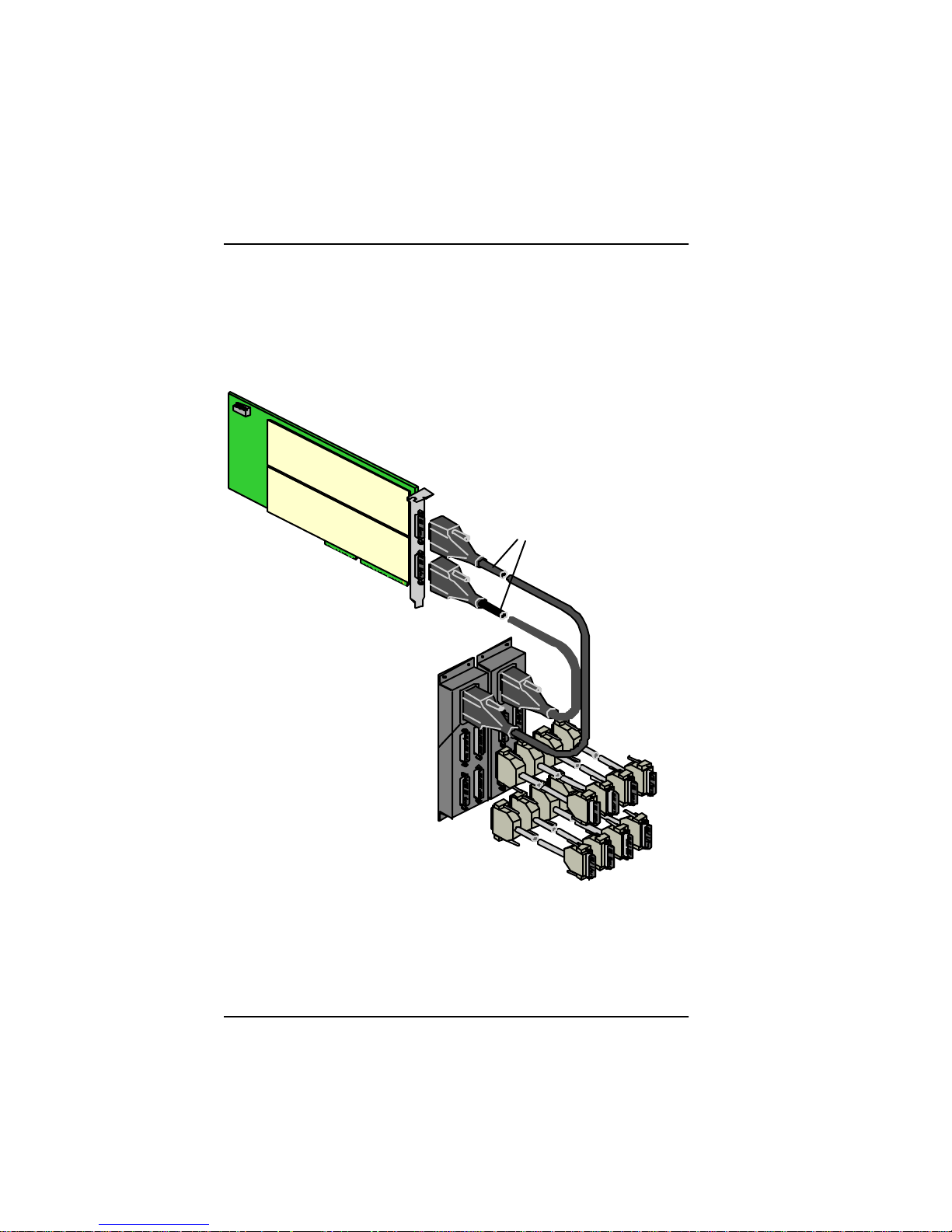
RLP
The RLP, an i960 RISC-based line processor, provides serial interfaces on the FRX6000.
RLP
LIC 1
LIC 2
RLP Cables
I/O Box
I/O Cables to Modems
and User Devices
6
4
5
2
0
3
1
7
Figure 1-2 RLP with I/O Box and Cables
1-2 FR X6000 Maintenance Gu i de, Rev 03
Page 13
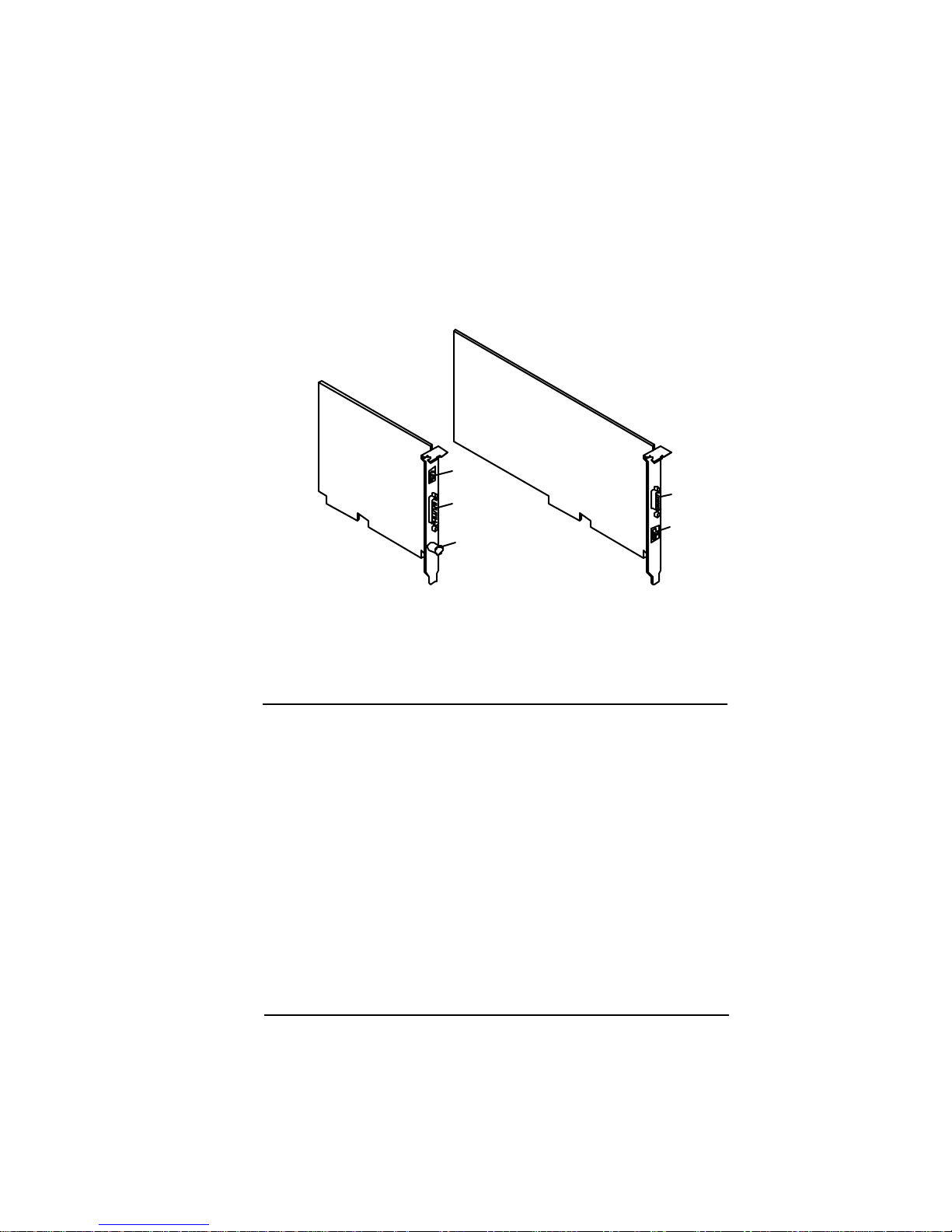
LAN Adapters
An FRX6000 ca n contai n one or two LA N c ards (T wo E the rne t, or
one Et hernet an d one To ken Ri ng).
Ethernet
RJ45
DB15
BNC
Token Ring
DB9
RJ45
F igure 1-3 La n Car ds
Operator Interfaces
The FRX6 000 does not requir e any operator in terv entio n for normal
oper ation . However, a keyboard an d VGA monitor are neces sary f or
local software installation , and a local monitor or local/remote asynchronous terminal (via the COM1 port) are necessary for configuration and monitoring.
The as ync term inal’ s keyboa rd must h ave
well as
[PgUp]
and
[PgDn]
keys.
[F1]–[F10]
function keys as
Ha r dwar e O ver v i ew 1- 3
Page 14

St a n da r d P C keyboa r d functi on ke y s ar e r epresen t ed as fol lows o n a
VT100. (
^[
is
, and th e fol lowing ch aracte r is an u ppercase l etter
[Esc]
O. )
Standard VT100
Keyboard
[F1] [PF1] ^[0P
[F2] [PF2] ^[0Q
[F3] [PF3] ^[0R
[F4] [PF4] ^[0S
[F5] [5] ^[0u
[F6] [6] ^[0v
[F7] [7] ^[0w
[F9] [,]
[F10] [.]
[PgUp] [Up Arrow] ^[0A
[PgDn] [Down Arrow] ^ [0B
Keypad Map to:
(comma)
(period)
^[0l
^[0n
Each FRX6000 is shipped with cables to allow connection to the
device f rom an ASCI te rminal or from a PC with term inal emulation.
(See Figure A-9 thro ugh Figure A-11. )
A keyboa rd and video device c an also be c onnec t ed vi a one of t hese
me thods:
●
ASCII terminal/key bo ard (or PC with terminal emula tion)
connected to an async PAD port in t he local FRX6000.
●
ASCII terminal/key bo ard (or PC with terminal emula tion)
connected to an async PAD port in a remote Cabletron frame
rel ay de vice (FRX6000, FRX4000, Smart Switch 1800, or
9W0 04 ) , through a network, into an X.25 p ort in th e local
FRX6000.
●
Ke yb oa r d a n d v i de o device o n a remote Ca b l et ron fr ame r el a y
device.
Remote monitoring and configuration of any FRX6000
with IP and SNMP co nfigur ed can be performed via
Cabletron’s Spectrum network management platform, or
via a Hewlett Pack ard® workstation with HP OpenView
an d Netlink OmniV iew.
1-4 FR X6000 Maintenance Gu i de, Rev 03
Page 15

Chapter 2
Diagnostic Procedures
All of the procedures in this chapter require an attached
VGA monitor. You should a lso have a diagnost ic diskette
(such as Ch eckIt ®) and a bo otable 1.4 MB blank d iskette,
t o analyze the system config uration.
Once an FRX6000 is opera tiona l, much diagnostic in for matio n is
avai lable through menu- level operatio ns (des crib ed in the Netlink
FR X40 00 & F RX600 0 Us er Guid e). Howev er, some probl ems might
arise that do not readily id entify themselves thro ugh system error
m ess ages or ob vious ch anges in o perati on. Thi s chapt er des cribes the
procedures for veri fying correct config uration and operation of an
FRX6000. It also provides some gu idelines for pursuing a solution if
there is a problem.
When an FRX6000 is switched o n, the following should oc cur :
●
The fan(s) and the power light on the front panel will come on.
●
BIOS identifying informatio n will be displayed.
●
There will be a short beep as me mory is tested , and the sc reen
will display the memory being counted.
●
Each disk drive’s access light will come on as the disks are
searched for the necessary DOS boot files.
●
As the softwa re i s l oa ded, me ssa ge s will be displa ye d.
If there are problems during boot-up, e rror messages will be displayed, and the process will c ontinue after the message has be en displayed for a short time (so watch the screen carefully).
Page 16

Once the software has correctly loaded, a screen similar to the following will be displayed.
Port S tatus Display (Page 1)
L P Type PPS Conn# State L P Type P PS Conn# State
0 0 X 25 62 4 Operational 0 1 X25 127 12 Operational
0 2 X25 112 7 Operational 0 3 X25 60 6 Operational
0 4 SNA 110 3 Operational 0 5 X25 87 5 Operational
1 0 A SY 0 0 Link_disab le 1 1 X25 88 4 Oper ational
F1: C ontinue
Nod e Name =node 10
F igure 2-1 Port Status Dis play
From this screen, you shoul d be able to lo g in to the Main Menu
(Figure 2-2) , w hich is the starting point for configuratio n and operat i o n proc edures.
2-2 FR X6000 Maintenance Gu i de, Rev 03
Page 17

Node Na m e = nod e 10
Softw are V ersion 4.0
M A I N M E N U
A Configuration
B O peration
C Status Displays
D Events
E Statistic s
F Reports
Se ke ct:
Figure 2-2 Main Menu
It can probably be asssumed that if you are reading this chapter, the
node did not boot corr ec tly as desc ri bed. The re mainder of t his
chapter describes steps for identifying and fixing some problems.
Certain problems may be easy to track down; for example:
●
If there seems to be no power at all, check to make sure the
power cor d is secure ly conn ected at b oth ends and th at ther e is
power (of the appropriate voltage) at the receptacle.
●
If there is power but the hardwar e does not see m to be functioning properly, verify the correct settin g of the AC vo ltage
selector swit ch. ( S ee Chapter 3.)
●
If t here is an ob vious problem with one or m ore ha rdw are
components, go to Chapter 3.
●
If the node appears to boot correctly but there is a communication problem with an async terminal, go to
"
COM Por t
Interface Controls" on page 2-20.
Diagnostic Procedures 2-3
Page 18
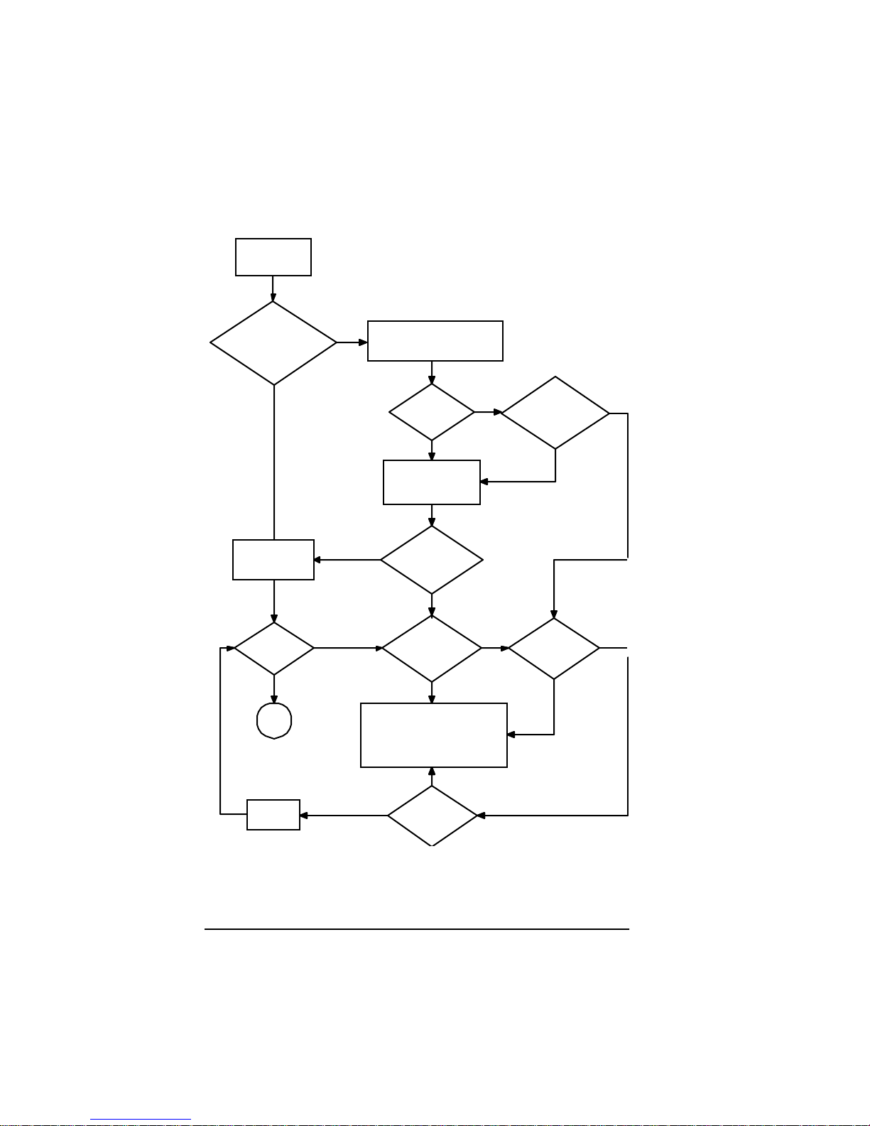
If the problem is less clear , follow thi s plan:
g
g
g
Power on and
monitor sc reen
messages
Is
FRX6000
software starting?
(should see boot
messages)
Reboot with diagnostic
No
diskette and
run diagnostics
Monitor boot
messages
(see
e 2-5
pa
Is
there still a
problem?
No
All
done
Fix, then
reboot
Yes
Was
problem
identified?
Run BIOS setup
(see
pa
then reboot
Is
Yes
)
Yes
Yes
FRX6000
software
starting?
Can you
identify the
problem?
Contact Cabletron Systems
Technical Support at:
Phone: 603-332-9400
FAX: 603-337-3075
E-mail: support@ctron.com
Can
you fix the
problem?
No
e 2- 17
No
No
No
Yes
),
Yes Yes
Can
BIOS setup
(
e 2-17
pa
fix it?
Yes
Can you
identify the
solution?
No
No
)
2-4 FR X6000 Maintenance Gu i de, Rev 03
Page 19

Review in g Boot Messages
As an FRX6000 boots, screen information tracks the loading of
cards, verifies configurati on file format, and displays any errors.
This data is displayed only until the FRX6000 software is running;
however, it is save d in a file named BOOTRP T.TXT , an d the op erator
can later display it in a report. Th is can b e used as a tool to verify that
startu p of the n ode proceed ed with out errors , or to remi nd the u ser of
the number and types of RLPs in the node. If th ere is an error
reported, the data may aid in fixing the problem.
I f a node is shut down, then re booted , t he exist ing BOOTRPT.TX T
file w ill be renam ed BOOTBAK.TXT, and a n ew BOOTRPT.TXT will
be creat ed. B OOTR PT.TXT and BOOTBAK.TXT can be u sed as
follows:
1. Display and re vi ew the data from the “c urre nt ” boot of the node .
2. Addr ess any report ed problems.
3. Re-boot the node. (This copies the previous boot data to a
backup file.)
4. Display the new boot data, and compare it to the previous dat a.
This will show whether the problem was fixed . Also, a problem
tha t occurred during the previou s boot-up will often be cleared
up by re-booting.
To display the data f rom the curren t b oot-u p, press
Menu (or
[F],
then
[C]
from the Main Menu). T o display the data from
[C]
at th e Re ports
the previous boot-up (s aved in a file calle d BOOTBAK.TXT), press
[D]
at the Reports Menu (or
Diagnostic Procedures 2-5
[F], [D]
from the Main Men u).
Page 20

Boot Messag es
Ma ny boot messa ges are “normal ” messages, an d are desc ribed here
simply for information. Others are err or messages, and include recomm ended actio n. Af ter takin g the reco mmended actio n for an error
message, reboot the node. If the problem has not been corrected,
contact Cabletron Systems Technical Support at:
Phone: 603-332-9400
FAX: 603-337-3075
E-mail: support@ctron.com.
Boot messages are listed below in alph abetical order.
Boot Time: nn/nn/19nn–nn:nn:nn
Meaning : This is the date and time of the current boot-up.
Action: None.
Buffers: Xmt count “n,” Xmt size “n,” Rcv coun t “n,” Rcv size “n”
Meanin g: These values denote the numbers and sizes of the
pre-fetch buffers u sed by the LAN in terface.
Action: None.
C a n’t I nit ia lize Me m ory , “NNN”.CMP
Meanin g: There is n ot enoug h me mory in the FRX6000 to
load the RLP software (if “
the VxWorks software (if “
NNN
NNN
” is "
” is "
BOOTUP
VXWORKS
") or
").
An FRX6000 has 1 MB of me mory, but onl y the
640 KB of base memory is needed to load and run
the software. If one of these messages is displa yed,
some of that base memory is faulty.
Actio n: Check all the installed memory for proper seatin g.
If it is all securely installed, replace each module
and r eboot, one at a time.
Can’t ope n CO FF f ile , “NNN”.CMP
Meani ng: Either th e co mpres sed boo t (if “
or VxWorks (if “
NNN
” is "
VXWORKS
NNN
BOOTUP
” is "
") file handle
")
could not be found during RLP software loading.
2-6 FR X6000 Maintenance Gu i de, Rev 03
Page 21

Actio n: Re-in stall the FRX600 0 software (as describe d in
Appendix C).
Checking configuration files
Meani ng: Self- explanato ry. Th e sof tware ch eck s to m ake su re
all files are valid.
Action: No ne.
Community Table file Read Error, System may not Boot Correctly
Meani ng: There is a e rror in the datab ase file C OM PAR. D AT.
Actio n: Boot the n od e with a DOS diskette and delete the
file, then reboot without the DOS disk and co nf igure new SNMP C ommuni ty T able records
(described in the User Guide).
Configured for Async Console: COM1 test failed/passed
Meanin g: During installation, the FRX6000 softwar e was
configured to use an async terminal for its video
interface. When the node boots , the software looks
for interrupts from the COM1 port.
Actio n: If the test fa ile d, r un a diagnostic utilit y to
dete rmine whether ther e is a n interrupt conflict, and
to test the COM port. (This requires a loopback connector on the COM port.) If the port fails, replace
the card that contain s it.
Conversion Error
Meanin g: T he datab a se file specified in the message dis-
played before this one (see
) was not successfully converted to the new
file ...
Converting (FILENAME)
rel e a se of F RX6 000 so f tw are.
Action: If the file is X25REC.DAT (node paramet ers), a n e w
default f ile will automatically be created. If an error
occurs in any other file, boot the node with a DOS
diskette and delete the file, th e n reboot without the
DOS disk and con figure a n ew file ( describ ed in the
User Guide).
Diagnostic Procedures 2-7
Page 22

Conversion Successful
Meanin g: The database file specified in the message dis-
played before this one (see
) was succ essfull y converted t o the new
file .. .
Converting (FILENAME)
release of FRX6000 software.
Action: None.
Converting (FILENAME) file ...
Meanin g: The software is converting the specified file from
the earlier release of FRX6000 software to the new
release. (This happens during migration to a new
releas e.) The number of database files that exist
depends on the configuration in the earlier release.
Action: None.
Could not register with FRX6000 LAN driver
Meani ng: There is a LAN card co nfigurat ion error.
Action: Check the CONFIG.SYS and PROTOCOL. INI files
to make sure the information shown in Appendix B
is in the files. ( If not, edit the file(s) using a DOS
editor .)
Creating X25rec.dat file ...
Meanin g: This message will follow
Conversion Error
erro r occurs during conversion of the node parameters file (X25REC.DAT).
Action: None—a new X25 RE C.DAT will be created auto-
matically.
if that
Database Error: ERRMSG.TXT Invalid Size
Meani ng: The ev ent message file (ERR MSG .TXT) w as cor-
Actio n: Boot the node with a DOS dis kette, then copy
2-8 FR X6000 Maintenance Gu i de, Rev 03
rupted during migration to a new release.
ERRMSG.TXT from the FRX6000 System Disk
(part of the installation set) to the directory
omni4000 on the hard di sk.
Page 23

Database Error: X.25REC.DAT Not Present, Expects (current release)
Meanin g: T he datab a se is missing the node parameters fil e
(X25REC.DAT). During bo ot-up, if this f ile is
missing, a new one is normally created automatically. Failure to cre ate this file indicates a serious
failure in the migration software.
Actio n: For an FRX6000, re-install the softwar e (as
described in Appendix C).
Database Initialization Error: ERRMSG.TXT not found
Meanin g: The file ERRMSG.TXT contains all the event mes-
sage s, and mu st be present in the s oftw are, but it is
missing.
Action: Boot the node with a DOS diskette and copy
ERRMSG.TXT fro m the FRX6000 System Disk
(part of the install ation set) to the d ir ectory
omni4000 on the hard disk.
Database Release “n” Matches Software Release, No Conversion
Necessary
Meanin g: Self -explan atory.
Action: No ne.
Database Validation Error: Version “n.nn”, Expected (current release)
Meanin g: T he versio n o f the database is incompatible with
that of the operatin g sy stem.
Action: Check all database records (accessible under
Database o per ation s from the FRX6000 Main
Menu, and described in the User Guide) for proper
configuration, and reconfigure where necessary.
Database Validation OK: Version “n.nn”
Meanin g: T he versio n of the database is co mpatible with that
of the operating system.
Action: Non e.
Diagnostic Procedures 2-9
Page 24

Database Write Error: X.25REC.DAT
Meaning : The node parameters file (X 25 REC.DAT ) could not
be written to the d a ta base during mig ration. This is
a severe error in hard disk operation.
Actio n: Run a diagnostic utility, then verify that the BIOS
(page 2-17) is correc tly s et u p. If ne cessary, replac e
the ha rd di s k dri ve .
Data Error: SubID “n” Skipped
Meanin g: A subscriber ID in the SNA PU file
(SDLCPU.DAT) do es not e xist in the SVC Subscriber file (SVCSUB.DAT), and the remote subscriber record will not be cop ie d to the new
database.
Action: Create a new PU record (described in the User
Guide).
Disk Error cannot create new (FILENAME)
Meani ng: There was an error in conv ertin g the fil e to the new
release . This is a severe error in ha rd d isk operation.
Actio n: Run a diagnostic utility, then verify that the BIOS
(page 2-17) is correc tly s et u p. If ne cessary, replac e
the ha rd di s k dri ve .
Disk Error, must create new X25REC.DAT
Meanin g: There was an error in converting the node param-
eters file (X25REC.DAT) to the new release, and a
new default file will be cr ea te d. This is a severe
error in hard disk opera t ion.
Actio n: Run a diagnostic utility, then verify that the BIOS
(page 2-17) is correc tly s et u p. If ne cessary, replac e
the ha rd di s k dri ve .
Disk Write error
Meanin g: There was an error in updating the file b e ing con-
verted to the new release. This is a severe error i n
hard disk operation.
2-10 FRX6000 Maintenance Guide, Rev 03
Page 25

Actio n: Run a diagnostic utility, then verify tha t the BIOS
(page 2-17) is correctly set up. I f necessar y, replace
the hard disk drive.
File Transfer Abort Error
Meanin g: Wh ile wa iting for a file transfer connecti on to
become established, an abort was attem pted from a
differe nt ID (the one in the message) tha n that used
to initiate the file trans fer request.
Action: The abort must be initiated from the same ID that
was used to initiate the file transfer .
Initialization Error: Can’t Attach RLP “n”
Meanin g: The RLP cannot be attached to the shared memory
buffer.
Action: Check th e IO address es of the RL Ps (see page B- 1)
for con flicts with other RLPs or other cards in the
node.
Initialization Error: Can’t Create Line Record/ Status Table
Meanin g: There i s a severe memory error.
Actio n: Check all the installed memory for proper seating.
If it is all securely installed, replace each module
and reboot, one at a time.
initLan: Could not allocate recv/xmit buffer “n”
Meanin g: There i s a severe memory error.
Actio n: Check all the installed memory for proper seating.
If it is all securely installed, replace each module
and reboot, one at a time.
IP Interface file Read Error, System may not Boot C orrectly
Meanin g: An er ror in the IP Interface file (IPIS UB.DAT)
occur red during IP initialization .
Action: Delete the file and c reate a new one by configuring
IP I nterface reco rds (described in the User Gu ide) .
Diagnostic Procedures 2-11
Page 26

IP Routing file Read Error, System may not Boot Correctly
Meanin g: An error in the IP Routing file ( IPRSUB.DAT)
occurred during IP initia lizat ion .
Action: Delete the file and create a new one by configuring
IP Routing records (descri bed in the User Guide).
LAN Adapter “n” open failed
Meanin g: An error occurred durin g IP in itia liz ation .
Actio n: Check the file P ROTOCOL.IN I (describ ed in
Appendix B) to m ake sure it is properly c onfigu red
for the inst alled LAN card(s).
LAN Adapter “n” open opened successfully
Meanin g: LAN card initialization was succ essf ul.
Action: None.
LAN Adapter “n” was already open
Meanin g: LAN card initialization was succ essf ul.
Action: None.
LAN driver not installed. Check CONFIG.SYS if desired
Meanin g: Se lf-ex planator y.
Actio n: Check the file CONFIG.SYS (described in
Appendix B) to m ake sure it is properly c onfigu red
for the inst alled LAN card(s).
“n” “n” LAN Interface “n” is configured for (LAN type) but has
hardware (type)
Meaning: Self-explana tory.
Actio n: Change the configur ation (see Appendix B) o r the
LAN card.
L oa ding LP “n” - RLP
Meani ng: The operatin g softwa re has bee n loaded to the spec-
ified RLP.
2-12 FRX6000 Maintenance Guide, Rev 03
Page 27

Actio n: None, unles s If an RLP that yo u k now is in stalle d
did not lo ad, in wh ich case rem ove it and check the
switch setting s to verify that it is configured correc tly.
Memory Test (“n”):”n,” Requests “n,” Outstanding Size “n”
Meaning : This is par t of normal IPL testing.
Action: Non e.
No Database Present, Creating a Database for Release “n”
Meanin g: Se lf-explanatory. During migratio n the first time a
node is booted with a new software release, a new
defau lt database will be created .
Actio n: Reconfigur e all da tabase files as nece ssary (see the
User Guid e) or copy the old database to the hard
disk. (See Chapter 3.)
No remote subscribers for subID “n”
Meanin g: N o PU re cords exi sted in the database for the spec-
ified SNA subscr iber (
subID
).
Action: Delete the SNA S ubscriber record or create the
missing PU records (described in the User Guide).
FRX6000 LAN driver retur ns error “n”, (29 means netbind was not run,
(mi.status)
Meani ng: There was an IPL p roblem .
Action: Sh ut down the node and check to assure pro per
seating of the LAN card(s). If the err or repeats on
rebo oting, rein stall the FRX600 0 sof tw are. (See
Appendix C.)
FRX6000 LAN driver V”n”.”n” bound to “n” cards. (Mi.ProtMajor,
mi.Pr ot Minor, m i.num Bound)
Meanin g: The LAN driver was loaded to th e cards.
Action: No ne.
Output Device: VGA
Meanin g: Self -explan atory.
Action: No ne.
Diagnostic Procedures 2-13
Page 28

Port Configuration file in Incorrect form, System may not Boot Correctly
Meaning : There is an incompatibility in the database, most
likely due to inc orrect migration to a new release of
FRX6000 softwa re .
Action: Make the necessary changes to the old database to
assure that it does not contain parameters that are
invalid in the new release, then reinstall the new
FR X 6000 s oftw a re (s ee Appendix C) and rep eat the
m ig ra ti o n pr o ce d ure.
PVC Configuration file Read Error, System may not Boot Correctly
Meaning : There is an incompatibility in the database, most
likely due to inc orrect migration to a new release of
FRX6000 softwa re .
Action: Make the necessary changes to the old database to
assure that it does not contain parameters that are
invalid in the new release, then reinstall the new
FR X 6000 s oftw a re (s ee Appendix C) and rep eat the
m ig ra ti o n pr o ce d ure.
Remote Connection Clearing Error (Remote Control ID)
Meani ng: An abort was attem pted fr om a diff erent ID ( the o ne
in the m e ssag e ) than that used to take r e mote
control.
Actio n: The abort must be in itia te d from the same ID that
was used to initiate remote contro l.
Remote Control Abort Error (Remote Control ID)
Meanin g: While waiting for a remote control connection to
Actio n: The abort must be in itia te d from the same ID that
RLP Load Complete
Meani ng: The operatin g sof tware h as been loade d to all RLPs
2-14 FRX6000 Maintenance Guide, Rev 03
become established, an abo rt was attem pted from a
different ID (the one in the message) than that used
to initiate the remote control request.
was used to take remote control.
in the FRX6000.
Page 29

Action: No ne.
SNMP System Defaults file Read Error, System May Not Boot Correctly
Meani ng: There is an err or in the databas e f ile X25REC. DAT .
Action: Boot the node with a DOS diskette and copy
X25REC.DAT fr om th e FR X60 00 Sys te m Di sk (p art
of the installation set) to the dir ector y omn i 40 00 on
the hard disk.
SNMP System Defaults file X25REC.DAT does not exist, System May
Not Boot Correctly
Meaning: Self-explanatory.
Action: Boot the node with a DOS diskette and copy
X25REC.DAT fr om th e FR X60 00 Sys te m Di sk (p art
of the installation set) to the dir ector y omn i 40 00 on
the hard disk.
Subscriber file Read Error, System may not Boot Correctly
Meanin g: There is an error in the database file SVCSUB.DAT.
Actio n: Boot the n od e with a DOS diskette and delete the
file, then reboot without the DOS disk and co nfigure new Subscriber parameters (described in the
User Guide).
Trap Routing Table file Read Error, System may not Boot Correctly
Meanin g: There is an error in the database file TRPPAR.DAT.
Actio n: Boot the n od e with a DOS diskette and delete the
file, then reboot without the DOS disk and co nfigur e n ew SNMP Trap Routin g records ( describ ed
in the User Guide).
Unknown Host message received MID “n,” BID “n”
Meanin g: An unknown message was received at the host dis-
patc her’s exchange from th e sp ecified port (
and ca rd (
BID
).
MID
)
Action: Includ e the displayed values in an incident r epo rt to
Cabletron Systems Technical Support .
Diagnostic Procedures 2-15
Page 30

Un k now n MAC t y pe “n”
Meani ng: There is a LAN card co nfigurat ion error.
Action: Check the CONFIG.SYS and PROTOCOL.INI files,
described in Appendix B, an d edit the file(s) if nec-
essary using a DOS editor .
Unknown Mbox ID in HOST message MID “n,” BI D “n”
Meanin g: A mess age was received at the h ost dispatch er’s
exchange from an unknown port (
(
).
BID
MID
Action: Include the dis play ed v alues in a n inc iden t report to
Cabletr on System s Technical Support .
VGA/EGA Display Card Installed
Meaning: Self-explana tory.
Action: None.
Waitfmsg Received Unknown MSG “n,” date “n”
Meani ng: An unknown message typ e was receive d at the host
dis patcher’s exchange.
Action: Include the dis play ed v alues in a n inc iden t report to
Cabletr on System s Technical Support .
) a n d card
Write Error: SubID “n” Skipped
Meanin g: A subscriber ID in the o ld d at abase’ s PU file
(SDLCPU.DAT) did no t exist in the SVC Subsc rib e r fil e (SVCSUB.DAT), and the PU recor d was
not be copied to the n e w database.
Action: Recreate the PU record (described in the User
Guide) if desired.
2-16 FRX6000 Maintenance Guide, Rev 03
Page 31

R unni ng th e B IO S Set up Pr ogr am
To operate properly, an FRX6000’s BIOS (basic input/output
system) needs to know the basic hardware and software configur ation: types of d isk drives, pr oce s sing s pee d, e tc. A s etup program
recor ds this configuration and st ores it in battery-back ed memory.
The BIOS is con figur ed before a node is shipp ed to the custo mer. If
you change the config ura tion (e.g., replacing the hard disk with one
of a different type), run the setup program to record the change(s).
1. Switch the unit on. Wh en (after a few seconds)
+ S> to enter Setup after Memory Check
of the screen, press (simultaneously)
is displayed at the bottom
[Ctrl] [Alt] [S]
Press <Ctr l + Alt
. After the
system memory has been checked, a screen similar to th e followin g will be displayed.
Texas Mi crosystems, Inc. —Setup Utility—Copyright (c) 1993
Model L486-SX—33 MHz—BIOS Version 3.1.1.1
Basic Options Time 16:07:30
Time an d Date Date De c 12, 1996
Fl oppy Di sk s Wee kd ay Th ur sda y
Fi x ed Di sks
Video Adapter Drive A: 3 1/ 2 In ch, 1.44 MB
Keyboard Drive B: Not Installe d
Shadow R AM Ha rd Disk 1 Type 46 is 482 MB
Boot Options Har d Disk 2 N ot Installed
Password Options Video A dapter V GA/EGA
Pa ss wo r d E di t
Advanced Options Base Me mory 640K
Park Hard Drive Extended Memory 1020K
Floating Print Unit Not Present
Fa st Bo o t No
Boot Drive Seque nce Drive A: then C:
101-Ke yboard NumLock Off
Password Protection None
Boot Error s:Keyboard On
Flopp y On
Vide o On
Figure 2- 3 Rackmount BIO S Setup M enu
Diagnostic Procedures 2-17
Page 32

2. Select items under
Basic Options
keys to highl ight the desi red entry , t hen pres s ing
by using the [ ] and/or [ ]
[Enter]
figure the various items as shown in Table 2-1. After a menu
selection is made, a parameter in tha t category will be displayed.
When that p aramet er is correctly configured, press
[Enter]
dis play the next one in that category or, if there are no more
parameters in the category, to redispla y th e Setup Menu.
Tabl e 2-1 B IO S Set up Parameter s
Basic Option Parameter Setting
Time a nd Date Time a nd Dat e correct tim e/date
Floppy Disks Onboa r d Fl oppy Controll er
Select Drive A: T ype
Select Drive B: T ype
Floppy Config Err or s
Fixed Disks Onboard IDE Interface
Set Hard Disk 1 Type
On
3.5", 1.44MB
N ot In st all ed
On
On
Type 46:
Siz e = 482,
Cylinde rs = 980,
Heads = 16, Write Precomp. = 0, Landing
Zone = 0, Sectors = 63 *
. Con-
to
Set Hard Disk 2 Type
Vi deo Adapter Sele ct Vi deo Adapter Type
Video Configurati on Errors
K ey board Ke yboard Config. Errors
Se t Ky bd . Ty p e m a t i c R at e sOnNo
Shadow RAM Shadow Select
CPU BIOS
Bo ot O ptions Set B oot Dri ve Sequence
Do you w ant Fast Booti ng?
101 Kybd NumLock a t Boot
Passwor d O pti ons P as sword Protect Options None
Password Edit
Do not configure
N ot In st all ed
VGA/ EGA
On
ROM
Shado w
Dri ve A: th en C:
No
Off
Advanced Options
Se rial Port s Se lec t Ser. Port 1 Ad dr es s
Select Ser. Port 2 Address
03F8h, IRQ4
02F8h, IRQ3
(continued on next page)
2-18 FRX6000 Maintenance Guide, Rev 03
Page 33

Table 2-1 BIOS Setup Parameters
Basic Option Parameter Setting
Parallel Por ts Select Par .l Port Address Disabled
Cache I nternal 486 Cach e
C0000H t o FFFFFH Cache
Non-Cac heable Mem Bloc k
DRAM Sp eeds Select DRA M Write Wait
States
Select DRAM Read Wait
States
Sel ec t DRAM RAS p r echa r g e
Sel ec t DRAM RAS to CAS
time
Bus /DMA Speeds AT Bus Speed
DMA Speed
CT206 Read/Write Wait States
8 Bit DMA W ait States
16 Bi t DMA Wa it States
Me mor y O p tions Set Ba se Memory Size
15M-16M Me mor y
Top 128K of 32M
Park Hard Drive
Ignore
* These ar e the settings for hard drives shipped from Ca bletron
December 1, 1997 or later. T he settings for drives shipped before that
date are:
Size = 201, Cylinde rs = 723, Heads = 15, Write Precomp. = 0,
Landing Zone = 0, Sectors = 38.
The sizes of both drives are actual ly much larger than the settings;
however , an FRX6000 requires less sp ace, and configuring the BIOS
as shown reduces disk access time.
Enable
Non Cacheable
Disabled
1 Wait State
2 Wait States
3 SYSCLKS
1 SYSCLKS
8 MHz
1/2 Bus Speed
3 Wait States
3 Wait States
3 Wait States
640K Base Mem
Disable 15M-16M
Disabl e Top 128 K
(contd.)
3. When everything is correctly configured, press
screen in Figure 2-3 (on p age 2-17) to s ave the set up and boot
the no de .
Diagnostic Procedures 2-19
[Esc]
at the
Page 34

COM Port Inter face Controls
DT R and RTS are disab led whe n the FRX6 000 is su es a bu s re set on
power -u p. When the nod e is ready to be gin u si ng th e serial inter face,
DTR and RT S will be r ai sed high.
While the system is running, DSR is used to indicate that the
equipment attached to the node is ready. While DSR is ON, the node
acc epts inp ut and p roduces out put o n the s erial inte rface . Whil e DSR
is OFF, the node stop s output and ignores input on the interface. The
response time of the node ( from DSR turning OFF until serial input/
output s topping) i s one se cond or less.
W i thi n one se cond of D SR turnin g O N, the no de r es u m es ou t put and
begins accepting input (b ased on 9600 bps-if serial I/O is slower, it
will take proportionately long e r). In operation, the node will finish
output of the screen in progress, then look at DSR; if it is OFF, n o
new output will o c cur. The effect is that when DSR changes from
ON to OFF, serial output might produce a full screen of characters
before stopping. This accounts fo r the time of one second or less at
9600 b ps. The sp eed of the serial out put, and any XOFF/XON, co uld
extend the time to finish the screen in p r og ress after DSR goe s OFF.
If DSR has mome ntary changes (i .e ., ON, OF F, ON), input and
output will be interrupted, and input characters will be discarded .
This case is seen in s ituatio ns where DSR is left unconnect ed or is
not driven. In such circumstances there is a possibility of noise
pickup on DSR. T o avo id thi s, connect DSR to a definite signal so a
level will ex ist on DSR in case s where it would oth erwis e be unconnected. If no signal is supplied by t he terminal equipment, connect
DSR directly to DTR on the COM1 in terface with an ind ustrystanda rd nul l modem.
The FRX6000 ignores RI and CTS signals on the COM port.
2-20 FRX6000 Maintenance Guide, Rev 03
Page 35

Chapter 3
Testing & Replacing Components
Several hardwar e c omponents of an FRX6000 c an be te sted and/or
replaced in the field by a qual ified service person. This chapter
describe s replaceme nt and installation of power supplies, dis k
drives, and fans, cards, and memory modules.
I f you want to back up the databa se before rep la cing a
hard disk drive, you w ill need a 3.5" 1.44MB diskette, formatted for MS-DOS version 5.0.
S tatic electricity can destroy the FRX6000 hardware.
Take the neces sary preca utions to discha rge any sta tic
b efore touchin g components or cards. If you have a
gr ounding wrist strap, wear it.
For reference , Figur e 3-1 through F i gure 3-3 show front, re ar , and
inte r ior views of the FRX 6 000 c has s i s.
Reset Switch
F igure 3-1 Rac kmount Chassis, Front Vi ew
Hard Disk Drive
3.5" Dis kette Driv e
Page 36

Power Switch
VGA Port
COM1
RLPs
Power
Cable
Connector
Voltage
Selection
Switch
COM2
Keyboard
Connector
LAN Adapter
LPT1
F igure 3-2 Rackm ount Chassis, R ear View
The combination of LP s and LAN Adapters might vary.
The VGA and COM1 ports are on a daughter card
mounted on the CPU (which also contains COM1 and
LPT1), with a cable to the connector in the adjacent slot.
3-2 FR X6000 Maintenance Gu i de, Rev 03
Page 37

Motherboard
Power
Supply
DC Power
Connector
Fans
Disk Drives
Fi gure 3- 3 Rackm ount Chassi s, I nte ri or V i ew
Testing & Replacing Components 3-3
Page 38

Removing the Chassis Cover
1. Make sure the power cable is dis connected fro m the rear of the
device.
2. Remove th e two screw s shown in the follo wing figure, then lift
the cover off.
Cover Screws
Figure 3-4 Removing the Chassis Cover
Testing Compone nt Vol tages
Be careful! These procedures are performed with
ex posed liv e AC and DC powe r.
To make sure certain components are transmittin g/re ceiving the
proper voltage s, follow this procedure:
1. Make sure the powe r switch is off, then disconnec t the p ower
cable from the rear of the unit.
2 . Re mo ve the un i t’ s cover.
3. Being caref ul to avoid con tact with live compo nen ts, reconnect
the power cable and switch the unit on.
3-4 FR X6000 Maintenance Gu i de, Rev 03
Page 39

4. Check the follo wing:
●
Power Supply :
◆
Me asure the AC v o lta ge.
◆
M ea sure the D C out put vol ta ges (+12V, -12V, +5V).
●
Motherboard:
◆
Measure the DC input voltages.
●
Disk Drives:
◆
Unp lug t he disk drive power connector and measur e the
DC input voltages.
◆
Test th e cont rol cable by substituting an oth er connecto r
or, if necessary, another cable.
◆
If a spare is available, test the disk controller card by substituting another one.
5. I f replacement of a component is necessary, follow the appropriate pro cedure lat er in this chapter.
Replacing the Power Supply
Location – see Figure 3-3 (on pa ge 3-3).
Cabletron part number = 84805006.
1. If neces sary, remove the cover. (See page 3-4.)
2. Disconnect the cables from the dis kette and hard drives .
Testing & Replacing Components 3-5
Page 40

Power Cables
Diskette Drive Hard Disk Drive
Figure 3-5 Disk Drive Cables
3. Disconnect the power supply cables from the DC power connector on the moth erboard. (See Fi gu r e 3-3.)
Power Connector
Orange Wire
Red Wire
Figure 3-6 Power Supply Cables
3-6 FR X6000 Maintenance Gu i de, Rev 03
Page 41

4 . R e move the fou r po we r supp l y moun t ing screw s fro m the bac k
of the node.
Power Supply Screws
F igure 3-7 Powe r Supply Mounti ng Screws
5 . Lift ou t the po w er su pp l y.
6. Install the re placement power supply by rev e rs ing the remova l
procedure.
Replacing the Hard Disk Drive
Location – see Figure 3-3 (on pa ge 3-3).
Cabletron part number = 85202001.
1. If you want to back up the database from the existing hard disk,
insert a DOS-formatted (5.0) dis kette into drive A and type (at
the DOS prompt):
copy c:\omni4000\*.dat a: [Enter]
.
2. If neces sary, remove the cover. (See page 3-4.)
3. R emove the th ree scr ews shown in the following figure, then
grasp the faceplate along the top edge and pull it forward and
down to pop it out.
Testing & Replacing Components 3-7
Page 42

Screws
Faceplate
Mounting
Bracket
Fi gure 3- 8 Remov i ng the Chassis F ac e plate
4. R emove the tw o screws (and the metal tabs under them) that
secure the drive (as shown in the fo llowin g figu re).
Hard Drive
Mounting Screws
See caution below
Faceplate (top view)
F igure 3-9 Re moving the Har d Dri ve
Be careful when disconnecting the faceplate that the
wires do not come unplugged.
3-8 FR X6000 Maintenance Gu i de, Rev 03
Page 43

5. Disconnec t the power and con trol le r cables fr om the har d dr ive.
(See the following figure.) If the mounting assembly that contains the drive has a ground wire attached, disconnect it.
Controller
Cable
Power
Cable
F igure 3-10 Hard Disk Dr i ve C ables
6. Slide th e drive out toward th e front.
7. Remove the drive from its m ountin g assembly by removing all
n ece ssa ry screw s.
8. Verify that the jump ers on the repl aceme nt drive are conf igured
to match the remov ed on e, if the same type, or per the accompanying documentation, if a diffe rent ty pe.
9. Install the d r ive by reversing the removal procedure.
1 0. Whe n t he new d ri ve has b e en i n s t a ll e d, re pl ace t he node’ s cover,
the n plug the power cord back into the u nit and the AC outlet.
11. Switch the unit on. When (after a few s econds)
+ S> to enter Setup after Memory Check
of the screen, press (simultaneously)
is displayed at the bottom
[Ctrl] [Alt] [S]
Press <Ctr l + Alt
. After the
system memory has been checked, a screen similar to th e followin g will be displayed.
Testing & Replacing Components 3-9
Page 44

Texas Mi crosystems, Inc. —Setup Utility—Copyright (c) 1993
Model L486-SX—33 MHz—BIOS Version 3.1.1.1
Basic Options Time 16:07:30
Time an d Date Date De c 12, 1996
Fl oppy Di sk s Wee kd ay T h ur sda y
Fi x ed Di sks
Video Adapter Drive A: 3 1/2 Inch, 1.44 MB
Keyboard Drive B: N ot I nstalled
Shadow R AM Ha rd Disk 1 Type 46 is 482 MB
Boot Options Har d Disk 2 Not Installed
Password Options Video A dapter V GA/EGA
Pa ss wo r d E di t
Advanced Options Base Me mory 640K
Park Hard Drive Extended Memor y 1020K
Floating Print Unit Not Present
Fa st Bo o t No
Boot Drive Seque nce Dr ive A: then C:
101-Ke yboard NumLock Off
Password Protection None
Boot Error s: Keyboard On
Flopp y On
Vide o On
F igure 3-11 BIOS Setup M enu
T he si ze displ aye d for H ard Disk 1 is 201MB for ha rd
drives shipped from Cabletron previou s to December 1,
997. The siz e of the drive is actually much larger than displayed; however, an FRX6000 requires less s pace, and
configur ing the BIOS as shown reduces disk access time.
12. Select
Fixed Disks
p rompted , s pecify
screen configure the hard disk as
from the Basic Options list at the left. When
Onboard IDE Controller
Type 46
as On, then at th e nex t
, and enter the asso-
ciated values from Table 2-1 (on p age 2-18).
13. When ev erything i s co rrectly config ured (see t he com plete setup
in Chap t er 2), p re ss
at th e screen in F i gu re 3- 11 to save the
[Esc]
setup and boot the node.
Installation is now complete. Go to Appendix C f or ins truction s on
installing FRX6000 software.
3-10 FRX6000 Maintenance Guide, Rev 03
Page 45

Replacing the 3. 5” Diskette Drive
Location – see Figure 3-3 (on pa ge 3-3).
Cabletron part number = 85208002.
1. If neces sary, remove the cover. (See page 3-4.)
2. R emove the th ree scr ews shown in the following figure, then
grasp the faceplate along the top edge and pull it forward and
down to pop it out.
Screws Faceplate
Mounting
Bracket
Figure 3-12 Removing the Chassis Faceplate
3. Remove the two screws (and the metal tabs under the m) that
secure the drive. (See th e following figure.)
Testing & Replacing Components 3-11
Page 46

Diskette Drive
Mounting Screws
See caution below
Faceplate (top view)
F igure 3-13 Re moving the D i s ke tte Drive
Be careful when disconnecting the faceplate that the
wires do not come unplugged.
4. Disconne ct the power an d control ler cabl es fr om the dr ive. (See
the follo wing figur e.) I f the mounting assembly that contains the
drive has a ground wire attached, disconnect it.
3-12 FRX6000 Maintenance Guide, Rev 03
Controller
Cable
Power
Cable
Figure 3-14 Diskette Drive Cables
Page 47

5. Slide th e drive out toward th e front.
6. Remove the drive from its m ountin g assembly by removing all
n ece ssa ry screw s.
7. Install the re placement drive by reversing the removal procedure.
Replacing the Fan Filter
Location – see Figure 3-3 (on pa ge 3-3).
Cabletron part number = 81005002.
1. If neces sary, remove the cover. (See page 3-4.)
2. R emove the th ree scr ews shown in the following figure, then
grasp the faceplate along the top edge and pull it forward and
down to pop it out.
Screws Faceplate
Mounting
Bracket
Figure 3-15 Removing the Chassis Faceplate
3. Remove the filter. (Se e the follo wing figure .)
Testing & Replacing Components 3-13
Page 48

See caution below
Faceplate (top view)
Figure 3-16 Remo ving the Fan Filter
Be careful when disconnecting the faceplate that the
wires do not come unplugged.
4. I nstall the replacement filt er by reversing the removal procedure.
Replacing a Fan
Location – see Fi gure 3-3 (on p a ge 3-3).
Ca bletron pa rt number = 81002005.
1. I f necessary, remove the cover. (See page 3-4.)
2. You must remo ve any cards that blo ck acce ss to the four screws
that secure the fan. (See the following figure.) Remove any
external cable(s) from each card.
Be sure to take the neces sary pr ecaut ions to discharg e
static electricity before touchin g a card, and place t he
card into an anti-static bag after removing it fro m the
FRX6000.
3-14 FRX6000 Maintenance Guide, Rev 03
Page 49

3. Remove the screw that secures each card ’s re ar bra cket into th e
node, then unplug and remove each card.
Air Flow
Clip
Card Guides
Screws
F igure 3-17 Re moving Fa ns
4. Before removing the screws that secure the fan, it may be necessa ry to remove a card guide. If so , pr y the top out with a small
slotted screw driver, then pop the bottom out.
5. Remove the fou r scre ws that secure the f an.
6. The like-colored wires from both fans are joi ned in connectors
on the mother board . T race the wires f rom the remov ed fan, pull
the top off of each connector, and discon nect the wires.
7. Remove the clips fr om the four corners o f the fan, in case they
are needed for the replacement.
8. Install the new fan by reversing the removal procedure. If necess ary, attach the four clips removed from the old fan.
Testing & Replacing Components 3-15
Page 50

Adding or Replacing Cards
Whe n a new or replaceme nt RLP or L ine Interface Ca rd is shipp ed
from Cab letron, it should include installation instructions. The information in this section is for reference.
1. Ma ke certain the d evice is powere d off, then remove the cover.
(See pa ge 3-4.)
2. Disconnect any cables from the rear of the card .
3. Remove th e retaini ng screw that secures the card’s mounting
bracket.
Retaining Screw Slot Cover
Card Guides
Gold-plated
Edge Connectors
Fig ure 3 -18 Ins talling a Card
3-16 FRX6000 Maintenance Guide, Rev 03
Page 51

4. Carefully p ull th e card up and out of the chas sis. Ha ndl e the card
only by its edges; never touch a gol d-pl ated e dge co nnector. (If
you do, clean it with a lint-fre e c loth dipped in isopropyl
alcohol.) Avoid tou ching any components except jumpers and
switches.
5. Place the card into an a nti-s tatic bag . If one is n ot handy, set the
car d aside until after step 6, then use th e bag that contained the
replacement card.
6. Remove the replacem ent car d fro m its anti-st atic bag. (Save th e
bag for any future need.)
7. If installing an RLP, set th e sw itc hes to match the configuration
of the removed card. If installing a Line Interface Card (LIC)
onto an RLP, mount it as sho wn in the drawing that accompanied the LIC. Each LIC has two connectors that mate to connector s on the R LP; make sure these are fully seated before
secur ing the board s tog ether with screws .
8. Insert the card into the card guide and lower it into the connector . Push gently , but firmly, on the card u ntil it is securely
seated.
9. Lock the card in place by re-installing the re ta ining scre w.
10. Replace the chassis cover.
11. Plug any cable(s) into the card an d tighten the retaining screws.
Testing & Replacing Components 3-17
Page 52

Page 53

Cards
On
8
1
Off
RLP
LIC 1
LIC 2
Appendix A
Configuration Drawings
LP Switch
8 76 54 3 2 1
0 OnOff*OffOnOffOnOnOn
1 OnOnOff
2OnOffOn
3 On Off Off
4 Off On On
5 Off On Off
6 Off Off On
7 Off Off Off
* Sw itch 7 is Off for 8 MB RLP,
On for 4 MB RLP.
RLP Cable
(60 conductors, one-to-one)
Cabletron part numbers
(each LIC part number includes
an RLP cable and four-port
I/O box):
RLP FRX6000-RLP
RS-232 LIC FRX6000-232-CRD
RS-422 LIC FRX6000-422-CRD
V.35 LIC FRX6000-V35-C RD
Each RLP in a node must have
a different number (0–7). That
number is det ermined solely by
the settings of the dipswitch.
Figure A-1 RLP and I/O Assembly
I/O Box
Page 54

W1 W2
No ROM Address
Software-configurable
I/O Base Address, IRQ,
RAM Base Address
Cabletron number = F RX6000-E-CRD
RJ45
DB15
BNC
Figure A-2 SMC EtherCard Plus
Software configuratio n of the SMC EtherCard is
des c ri b e d in Appendix B.
W1 W2
No ROM Address
Software-configurable
I/O Base Address, IRQ,
RAM Base Address
Left LED is green during loopback test
Right LED is amber when adapter is connected
to Token Ring network
UTP
10 Base T
UI
Thicknet
10 Base 5
Thinnet
10 Base 2
LEDs
DB9
STP
RJ45
UTP
A - 2 FR X6000 Maintenance Gu i de, Rev 03
Cabletron number = F RX6000-T-CRD
Figure A-3 SMC Token Card Elite
Software configuratio n of the SMC TokenCard is
des c ri b e d in Appendix B.
Page 55

On
Off
4 1
Hard Drive
Connector
Hard Drive
Connector
JP1 JP2 JP3 JP4
JP10
CPU
Keyboard
Connector
JP15
JP12
JP14
VGA
Module
Figure A-4 CPU Module
Ju mper Functions ( a s shown)
JP1,2, 3 N/A
JP4 E nable on-board battery
JP5 IDE LED
JP6,7,8 N/A
J P10 48 6S X pr o c es s or (st andard )
JP12 Disable watchdog timer
JP14 N/A
JP15 (leave in factory default positi on s hown)
COM1
LPT1
Configuration Drawings A-3
Page 56

Cables
I/O Cables
Note “IO” label at this
end of DCE version
To FRX4000
IO
13 1 1 13
25 14 14 25
Physical DCE Physical DTE
(Female Connector) (Male Connector)
Cabletron part numbers:
DCE FRX-232DCE-CAB
DTE FRX-232DTE-CAB
(Note that DTE cable is
straight-through)
Pin
1 FGnd 1 FGnd
2TD 2TD
3RD 3RD
4RTS 4RTS
5CTS 5CTS
6 DSR 6 DSR
7 SGnd 7 SGnd
8DCD 8 DCD
15 TC 15 TC
17 RC 17 RC
20 DTR 18 LL
22 RI 20 DTR
Signal Pin Signal
21 RL
22 RI
25 TM
Figure A-5 RS-232 C ables
A - 4 FR X6000 Maintenance Gu i de, Rev 03
Page 57

To FRX4000
Cabletron part numbers:
DCE FRX-V35DCE-CAB
DTE FRX-V35DTE-CAB
AA C A A C
Physical DCE Physical DTE
(Female Connector) (Male Conn ector)
Pin
A FGnd A FGnd
B SGnd B SGnd
CRTS C RTS
DCTS D CTS
E DSR E DSR
FDCD F DCD
HDTR H DTR
PSDa K LT
R RDa P SDa
S S Db R RDa
T RDb S SDb
UTTa T RDb
VRCa U TTa
WTTb V RCa
XRCb WTTb
YTCa X RCb
AA TCb Y TCa
D B B D
Signal Pin Signal
AA TCb
AA
Configuration Drawings A-5
Figure A -6 V. 35 C ables
Page 58

To I/O Box
19 1 1 19
37 20 20 37
Physical DCE Phy sical DTE
(Female Connector) (Male Connector)
Cabletron Part Numbers:
DCE FRX-449DCE-CAB
DTE FRX-449DTE-CAB
Pin
1 FGnd 1 F Gnd
4SDa 4SDa
5SCa 5SCa
6RDa 6 RDa
7RTSa 7 RTSa
8RCa 8 RCa
9CTSa 10 LL
11 DMa 12 TRa
12 TRa 13 RRa
13 RRa 14 RL
17 TTa 17 TTa
19 SGnd 18 TM
20 SGnd 19 SGnd
22 SDb 20 SGnd
23 SCb 22 SDb
24 RDb 23 SCb
25 RTSb 24 RDb
26 RCb 25 RTSb
27 CTSb 26 RCb
29 DMb 30 TRb
30 TRb 31 RRb
31 RRb 35 TTb
35 TTb 37 SGnd
37 SGnd
Signal Pin Signal
Figure A-7 RS-449 C ables
A - 6 FR X6000 Maintenance Gu i de, Rev 03
These cables p rovid e RS -44 9 interfaces f or an RS422 Line Interface Card.
Page 59

To FRX4000
Cabletron Part Numbers:
DCE FRX-X21DCE-CAB
DTE FRX-X21DTE-CAB
81 18
15 9 9 15
Physical DCE Physical DTE
(Female Connector) (Male Connector)
Pin
1 FGnd 1 FGnd
2 TDa 2 TDa
3Ca 3 Ca
4 RDa 4 RDa
5Ia 5 Ia
6 CLKa 6 CLKa
8 SGnd 8 SGnd
9 TDb 9 TDb
10 Cb 10 Cb
11 RDb 11 RDb
12 Ib 12 Ib
13 CLKb 13 CLKb
Signal Pin Signal
Figure A -8 X. 21 C ables
These cables provide X.21 interfaces for an RS-422
Line Interface C ard.
Configuration Drawings A-7
Page 60

Auxiliary Console Cables
To FRX6000 COM1
Pin
1DCD
2RD
3TD
4DTR
5 SGnd
6DSR
7RTS
8CTS
9RI
Signal
Female Connector
Cabletron Part Number:
FRX-PC-CAB
51
96
Figure A -9 Auxiliar y Consol e Cable, FRX6000 to PC
Pin
2 TD
3 RD
4 RTS
5 CTS
6 DSR
7 SGnd
8 DCD
20 D TR
22 R I
Signal
13 1
25 14
Female Connector
Cabletron Part Number:
FRX-9/25-ADAP
9-pin end plugs
into FRX-PC-CAB
Figure A-10 Console Cable Converter, FRX6000 to Terminal
A - 8 FR X6000 Maintenance Gu i de, Rev 03
Page 61

To FRX6000 COM1
Cabletron Part Number:
FRX-MOD-CAB
Pin
2TD
3RD
6DSR
7 SGnd
20 DT R
Signal
113
14 25
Male Connector
Figure A -11 Auxiliary Co nsole Cable, FRX 6000 t o Modem
Configuration Drawings A-9
Page 62

Page 63

Appendix B
Configuring LAN Card Software
The LAN cards currently available are the SMC® E therCard Pl us
Ethern et adap ter and the SM C Token Card E lite T oken Ring adapter.
An IBM Auto 16/4 Token Ring ISA adapter is also supported. Each
card requires running a program to configure the operatin g parameters.
If a LAN card i s in sta lle d after the FRX600 0 softwar e
has bee n inst alled, a pa rtial r e-installation of the
software must be run to specify the LAN card(s). (See
Ap pendix C.)
If tw o o f the same typ e o f L AN car d a re to b e i nst al led ,
m ake sure only one is insta lled when the program is
run the firs t time. T hen in stall t he se cond ca rd and run
the program again.
Some config ured addresseses must be different for each card in a
node. F or re fer enc e, Tabl e B-1 li sts addres ses us ed by the RLPs
(when a VGA car d is installed, which is s tandard).
Table B-1 RLP Addresses
Shar ed Memo ry
RLP
No.
0 CC00: 0— C DFF:F 4 308
1 CE00:0—CFFF:F 470 8
2 D000:0—D1FF:F 4B08
3 D200 :0—D3FF: F 4F08
4 D400:0— D5FF :F 5 308
5 D600:0— D7FF :F 5 708
6 D800:0—D9FF:F 5B08
7 DA0 0:0—D BFF:F 5F08
Ba se Address (hex)
Starting—Ending
I/O Base
Ad dr es s (h ex )
Page 64

If the node contains two LAN cards, t here can be no
RLP 6 or 7. This should not be a problem, however,
since when there are two LAN cards, the no de suppo rt s a ma xi m um of si x R LP S , a n d t h e s e c a n b e numbered 0–5.
If an RLP is not installed, its allotted shared memory addresses will
be used by the RLP with the next higher RLP number, and each successive RLP will use the sha red memory address es left av a ilable by
the on e bef ore it.
The I/O base address always matches the RLP n umber as shown in
the table; it does n ot ch ange if an RLP is not installed. (RLPs use four
I/O addr e sses; e.g.,
4308–430b
).
SMC Ether Card Configuration
1. Make sur e th e car d’s jumper s are config ur ed as shown in Figure
A-2.
2. Bo ot th e unit with a DOS (5 . 0) system disk.
3. At the
type
4. At the License screen, select
5. At the next scr een, sel ect
6. At the next scr een, sel ect
7. In the Addres s Mode box, select
pr ompt, i nsert the SMC SuperDisk Ve r s io n 2.4, the n
A:>
ezstart
and press
[Enter]
.
Yes
Custom
.
Setup
.
.
Memory Mapped
. This will
display a Memory Address option.
If this is the first or on ly LAN card installed, se lect
is the second LAD car d (of any type), select
D800
C800
.
. If this
8. Co nfigure th e remaining para meters as shown in the f ollowing
li s t. S ome va lues dif fer depe nding on whether the c ar d being
configured is the first/only or second LAN card in the node.
B - 2 FR X6000 Maintenance Gu i de, Rev 03
Page 65

Parameter Settin g
Zero Wait State Enabled No
Plug and Play Adapter Disabled
I/O Base Address
IRQ
Bo ot RO M Dis a ble d
Network Interface Auto Media Detect
The card requires 32 contiguous I /O addresses (e.g. ,
1
If card 0 is IBM Token Ring and card 1 is SMC Ethernet, the IRQ
2
for the SMC card will automatically b e set to 10.
1
1st/only card:
2n d ca rd:
1st/only card:
2n d ca rd:
240
280
10
2
5
hex
hex
240-260
).
9. Save the configurat ion, then back out of the setup by selecting
Previous
, then
Exit
.
SMC TokenCard Configur at ion
1. Make sure the card’s ju mpers are configured as shown in
Figure A-3 .
2. Bo ot th e unit with a DOS (5.0) system disk.
3. At t he
type
ezstart
prompt, ins ert the SMC
A:>
and press
[Enter]
SuperDisk
. The EZStart main menu will be
Ve r si o n 5.0, the n
displaye d, showing the curr ent configura tion of any installed
SM C Tok en Ring adapt er(s).
4. I f there are two Token Ring cards installed, select the adapter
nu mb e r (
5. Select
Conf ig uring LA N Card So ftware B-3
Select Adapter
Custom
I/O Base Address 240
IRQ 10 5
RAM Base Address C800
ROM Enabled None None
Network Interface 4/16 UTP/STP
Early Token Release Yes Yes
IIf the node contains only one LAN card, it must be card 0.
1
The card requires 32 contiguous I /O addresses (e.g. ,
2
The selection of UTP or STP can be changed later by rerunning
3
the setup program.
, then configure the card as follows:
).
Card 0
hex
hex
1
2
Card 1
280
D800
3
4/16 UTP/STP
2
hex
hex
240-260
3
).
Page 66

I BM Toke n Ri ng Ad a pt er Conf igu ration
1. Make sure the car d is installed, then insert A uto 16/4 Token Rin g
I SA Adapter Diagnostic & Configuration P r ogr am disk into
dr ive A a nd press (si multaneous l y)
[Ctrl] [Alt [Del]
.
2. When the screen displays
3. At the
A:>
pr ompt, ty pe
autocfg /v
Starting PC-DOS
an d pres s
, press
to display a scr ee n listing all p ossible options, type
[Enter]
.)
[Enter].
[F5]
.
(If you w ant
autocfg
4. The current (o r default) configuration of each installed IBM
card will be displayed. Make the necessary change(s) by
select in g a card, then ty pin g
autocfg
f ol l o w ed b y a s m a ny of the
following s witches as necessary.
Op tion
Card
Sta te
Autosense
Data Rate
RPL
I /O B ase 1st card:
RA M Base 1st ca rd:
RAM Range
RO M Base 1st ca rd:
Mem Ctl
Interru pt 1st c ard :
* Autosense will auto matically read and set the ring speed for each
card except the first card in the ring. For t he first card in the ring,
set Autose nse to
IBM Token Ring cards (that are software-configurable), set
Autosense t o ON and leave the Data Rate at the default setting.
Neces sary Value Switch
0
1/c1
or
Active /a /f 1
ON
*
4
16
or
MB/sec *
Disabled /p 1
0A20
hex
2nd card:
2nd card:
2nd card:
2nd card:
OFF
0A24
hex
C800
hex
D800
hex
16 K /s 16
DC00
hex
DE00
hex
16-bit / b 16
IRQ-09 /n 9
IRQ-10 /n 10
, an d configure a Data Rate. For all other
/t 1
/d 4
/i a20
/i a24
/r c8
/r d8
/o dc
/o de
or
or
/c 2
/d 16
For exam ple, if ch anges m ust be made to make the st ate Active ,
disable RPL, and set the Interrupt to 10, typ e
/a /f 1 /p 1 /n 10 [Enter]
B - 4 FR X6000 Maintenance Gu i de, Rev 03
autocfg /c 1
(or 2)
.
Page 67

5. Type
autocfg /c 1
(or 2)
/v [Enter]
again to view the up dated settings. When everything is the way you wan t it, type
(o r 2)
/x [Enter].
autocfg c 1
6. Remove the diskette and press
[Ctrl] [Alt [Del]
to re boot the node .
Star t up Fil es
CONFI G.SYS
Whether the node contains one or two SMC Ethernet cards,
CONFIG.SYS will contain the following line :
DEVICE=\OMNI40 00\SMCMAC8000.DOS
The presence of Tok en Ring cards does not affect CONFIG.SYS.
PROTOCOL.INI
PROTOCOL.INI will always contain the following lines:
[PROTOCOL_MANAGER]
DriverName = PROT M AN$
Card-specific part,
shown later
Conf ig uring LA N Card So ftware B-5
RECVBUFSIZE= 1514
RECVBUFS=20
XMITBUFSIZE=1514
XMITBUFS=20
I P LIMIT = 1 0
SNALIMIT = 10
IPXLIMIT = 10
I P P RIO RITY = 1
IPXPRIORITY = 3
SNAPRIORITY = 2
;**** END OF FILE ****
Page 68

When one or two LAN cards are installed, PROTOCOL.INI al s o
contains the card-specific lines shown below.
L AN ca rd 0 = S MC Etherne t , card 1 not inst alled:
; SM C Ethernet Adapter
[SMCMAC8001]
DriverName = SMCMAC8000$
IOBase = 0x240
IRQ = 10
RamAddress = 0xc800
; NETLINK NDIS Protocol Driver
[OMNI4000]
DR IV E RNAME = AMNET$
BINDINGS = SMCMAC8001
LAN ca rds 0 and 1 = SMC Et hernet:
; SM C Ethernet Adapter
[SMCMAC8001]
DriverName = SMCMAC8000$
IOBase = 0x240
IRQ = 10
RamAddress = 0xc800
; SM C Ethernet Adapter
[SMCMAC8002]
DriverName = SMCMAC8000$
IOBase = 0x280
IRQ = 5
RamAddress = 0xd800
; NETLINK NDIS Protocol Driver
[OMNI4000]
DR IV E RNAME = AMNET$
BINDINGS = SMCMAC8001,SMCMAC8002
L AN ca rd 0 = S MC Toke n R i ng, card 1 not inst alled:
; SMC TokenCard Elite
[SMC8100_NIF]
DriverName = SMC8100$
IOBase = 0x240
; NETLINK NDIS Protocol Driver
[OMNI4000]
DR IV E RNAME = AMNET$
BINDINGS = SMC8100_NIF
B - 6 FR X6000 Maintenance Gu i de, Rev 03
Page 69

L AN ca rds 0 and 1 = S MC Toke n R ing:
; SM C TokenCard Elite
[SMC8100_NIF]
DriverName = SMC8100$
IOBase = 0x240
; SM C TokenCard Elite
[SMC8102_NIF]
DriverName = SMC8100$
IOBase = 0x280
; NETLINK NDIS P rot oc ol Driv e r
[OMNI4000]
DRIVERNAME = AMNET$
BINDINGS = SMC8100_NIF,SMC81002_NIF
L AN ca rd 0 = S MC Etherne t , card 1 = S MC Toke n R ing:
; SM C Ethernet Adapter
[SMCMAC8001]
DriverName = SMCMAC8000$
IOBase = 0x240
IRQ = 10
RamAddress = 0xc800
; SM C TokenCard Elite
[SMC8100_NIF]
DriverName = SMC8100$
IOBase = 0x280
; NETLINK NDIS P rot oc ol Driv e r
[OMNI4000]
DRIVERNAME = AMNET$
BINDINGS = SMCMAC8001,SMC8100_NIF
LAN card 0 = SMC Token Ring, card 1 = SMC Ethernet:
Conf ig uring LA N Card So ftware B-7
; SM C TokenCard Elite
[SMC8100_NIF]
DriverName = SMC8100$
IOBase = 0x240
; SM C Ethernet Adapter
[SMCMAC8001]
DriverName = SMCMAC8000$
IOBase = 0x280
IRQ = 5
RamAddress = 0xc800
Page 70

; NETLINK NDIS Protocol Driver
[OMNI4000]
DR IV E RNAME = AMNET$
BINDINGS = SMC8100_NIF,SMCMAC8001
L AN ca rd 0 = IBM Token R i ng, card 1 not inst all ed:
; IBM Token Ring Adapter
[NLK_TOK]
DriverName = NLK_TOK$
shared_ram = 0xC800
bridge_bufsize = 1072
bridge_use64k = “N”
; NETLINK NDIS Protocol Driver
[OMNI4000]
DR IV E RNAME = AMNET$
BINDINGS = NLK_TOK
L AN ca rds 0 and 1 = IBM Token R ing:
; IBM Token Ring Adapter
[NLK_TOK]
DriverName = NLK_TOK$
shared_ram = 0xC800
bridge_bufsize = 1072
bridge_use64k = “N”
; IBM Token Ring Adapter
[NLK_TOK2]
DriverName = NLK_TOK2$
shared_ram = 0xD800
bridge_bufsize = 1072
bridge_use64k = “N”
; NETLINK NDIS Protocol Driver
[OMNI4000]
DR IV E RNAME = AMNET$
BINDINGS = NLK_TOK,NLK_TOK2
L AN ca rd 0 = IBM Token R i ng, card 1 = S MC Etherne t :
; IBM Token Ring Adapter
[NLK_TOK]
DriverName = NLK_TOK$
shared_ram = 0xC800
bridge_bufsize = 1072
bridge_use64k = “N”
; SM C Ethernet Adapter
B - 8 FR X6000 Maintenance Gu i de, Rev 03
Page 71

[SMCMAC8001]
DriverName = SMC M AC8000$
IOBase = 0x280
IRQ = 10
RamAddress = 0xc800
; NETLINK NDIS Protocol Driver
[OMNI4000]
DR IV E RNAME = A MNET$
BINDINGS = NL K_TOK ,SMCMAC8001
L AN ca rd 0 = IBM To ken Ri ng, card 1 = SMC Toke n R i ng:
; IBM Token Ring Adapter
[NLK_TOK]
DriverName = NL K_TOK $
shared_ram = 0xC800
bridge_bufsize = 1072
bridge_use64k = “N ”
; SMC TokenCard Elite
[SMC8100_NIF]
DriverName = SMC 8100$
IOBase = 0x280
; NETLINK NDIS Protocol Driver
[OMNI4000]
DR IV E RNAME = A MNET$
BINDINGS = NL K_TOK ,SMC8100_NIF
L AN ca rd 0 = SMC Ethernet, ca rd 1 = IBM Token R i ng:
; SM C Ethernet Adapter
[SMCMAC8001]
DriverName = SMC M AC8000$
IOBase = 0x240
IRQ = 10
RamAddress = 0xc800
; IBM Token Ring Adapter
[NLK_TOK]
DriverName = NL K_TOK $
shared_ram = 0xD800
bridge_bufsize = 1072
bridge_use64k = “N ”
; NETLINK NDIS Protocol Driver
[OMNI4000]
DR IV E RNAME = A MNET$
BINDINGS = SMC MAC 8000,NLK_TOK
Conf ig uring LA N Card So ftware B-9
Page 72

LAN card 0 = SMC Token Ring, card 1 = IBM Token Ring:
; SMC TokenCard Elite
[SMC8100_NIF]
DriverName = SMC8100$
IOBase = 0x240
; IBM Token Ring Adapter
[NLK_TOK]
DriverName = NLK_TOK$
shared_ram = 0xD800
bridge_bufsize = 1072
bridge_use64k = “N”
; NETLINK NDIS Protocol Driver
[OMNI4000]
DR IV E RNAME = AMNET$
BINDINGS = SMC8100,NLK_TOK
B-10 FRX6000 Maintenance Guide, Rev 03
Page 73

Appendix C
Installing FRX6000 Software
This procedure requires a locally attached k eyboard and
VGA monitor.
If the FRX6000 contains any LAN adapters, the configuration programs that came with the cards must be run
be f ore installin g FRX6000 software .
M ake sure you have any pa tch diskettes as well as the
st andard installat ion set.
If a s oftw are error oc curs that can be tr aced to a spe cific file ( po ssib ly
identified in a message at bo ot-up), copyin g that file from the appropriate FRX6 000 insta lla tion disk will often fix the problem. Sometimes, however, it is n ec e ssary to reinsta ll all of the so f tw are to
ensure proper operation.
Naturally, if a problem requires replacing the hard disk drive, the
s of t w are mu st be i ns t al l ed onto the n e w di s k. I f the probl em did not
corru pt the datab ase and if th e ha rd disk is accessible, the d atab ase
can be backed up to diskette, then copied to the new hard disk after
the FRX6000 so ftware has been i nstalled. The softw a re, ho wever,
should be r einstalled from the installation diskettes, to guarantee that
uncorrupted file s will be installed.
1. Disconnect all LP and LAN card cables from either the rear of
the node or the local d evi ces at the oth er ends.
2 . In sert the FRX600 0 Syst em D is k in to d iskette dr ive A and switch
the node on, or press
3. A mess a ge concern ing LAN card configurati on will be displayed. When prompted:
[Enter]
Backing up the database and replacing the hard drive are
described on page 3-7.
[Ctrl] [Alt] [Del]
Strike any key when ready
.
if already on.
, press
Page 74

4. You will be asked
figure your FRX6000? [N]
: W ill you be using an A sync termi nal to con-
. An F RX6000 can be configured and
controlled from a local key board and VGA monitor, or an
ASCII terminal (with keyboard) connected to the node:
◆
vi a direct cable or modem to the node’s COM1 serial po rt.
◆
via an async PAD port in the local node.
◆
via an async PAD port in a remote FRX6000, through a
network, into an X.25 port in th e local node.
Press
and go to step 5 or pre s s
[Y]
and go to step 6.
[N]
Make sure your selection matches th e hardware
co nfiguration of th e node and its video device. An
async te r minal ca nnot be used if no t s pecified
h ere.
5. When prompt ed for a ter min al sp eed, ty pe th e line spee d (in bits
per second) of the attached terminal (
and press
6. You will be asked:
LAN adapter configuration?
to accept t he de fault o f N. If you are simply changing the
[Enter]
[Enter]
.
Are you changing only the Async console or
If this is a new installation, press
console or LAN card setup, press
1200, 2400, 4800
and go to step 9 .
[Y]
, or
9600
Even if you want to change only the console setup,
you will have to redo the LAN card setup (if cards are
installe d), since chan gin g the terminal setup writes
over a file th a t contains the specifications for the ter minal and the L AN cards.
7. Files will be copie d in to the directory OMNI4000 and the root
directory (which will b e created if neces sary) . When pr ompted ,
insert FR X60 00 P r oto col Disk 1 and press
[Enter]
.
)
8. More files will be copied in to OMNI4000. When prompted,
insert FRX6000 Protocol Disk 2 and press
9. If th is is a full in stalla tion, more files will be copied from Pro-
tocol Disk 2. Eve ntua lly you w ill be asked:
have you installed (0-2)?
I f none, press
11. Oth erwise, en ter the n umber of LA N card s and go to step 10.
C-2 FRX 6000 M aintenanc e Guide, Rev 03
[Enter]
.
[Enter]
How many LAN cards
to accept the default o f 0, then go to st ep
Page 75

10. You will be a sked to specify the ty pe o f LAN card 0. (LAN
cards are numbere d
and 1.) En te r th e app ro priate n um be r from
0
the choices:
3 – SMC EtherCard Plus Elite16
4 – IBM Token Ring Adapter
5 – SMC TokenCard Elite
If only one LAN ca r d is installed, go to step 11. If tw o are
installed, repeat s tep 10 for the second card, then go to step 1 1.
11. T he bas ic installatio n is no w com plete. If y ou are insta lling
patch software, go to step 12; otherwise go to step 13.
12. I f you are installing one or more patches, rep eat this procedure
for each patch (in order): Insert the pa tch dis kette into th e driv e
and re-boot the node. The software will be installed automatically.
1 3. If r e s t ori n g a backe d up da ta b a s e, go t o s t ep 1 4; ot h e rw is e , go to
step 15.
14. I ns ert the backed up databas e diskett e into dr ive A and at the
DOS prompt type :
copy a:\*.dat c:\omni4000 [Enter]
.
15. Remove the diskette, then press
[Ctrl] [Alt] [Del]
to r ebo ot t he
node. Watch the power-up and boot messages for any sign of
problems.
16. When boot-up is complete, the Port Status Displ ay (Figure 2-1
on p a ge 2-2) will appear . Log in by pressin g
and entering
[F1]
your FRX6000 password.
17. At the Main Men u, press
[F]
, t h en
to di s p lay the boot re p ort.
[C]
(See "Re vi e w i ng Bo ot Me s sa ge s " on pa ge 2-5 . Review the
report for error messages.
18. Press
[F]
, t hen
at the Main Menu to create a config uration
[A]
report. Review this report for any problems. If problems are discover ed in either this or the b oo t report that you cannot solve,
contact Cabletron Sys tems Technical Support.
19. Once everything seems to be operational, create a new database
if necessary (by configuring new records as described in the
FRX4000 & FR X6000 U s er G ui d e ), then r eco nnect the RLP and
LAN card cables and make sure connections can be es tablished
betw een users.
Installing FRX6000 Soft ware C-3
Page 76

Page 77

B
BIOS setup
BOOTBAK.TXT
BOOTRPT.TXT
Boot-up inform ation, displaying
Bootup message s
2-17
2-5
2-5
2-6
C
Car d s, insta lling
Chassis options
COM port , seria l interface controls on
Components, replacing
CONFIG.SYS
Configuration draw ings
3-16
1- 1
3-1
B-5
A- 1
D
Dat abase
backing up
re storing
Diskette drive
C-1
C-3
3- 11
E
E t h erne t c ard , S M C
B-2
Index
2-5
2-20
F
Fa n filter
Fa n s
Function keys
3-13
3-14
1- 4
H
Hard disk drive
3-7
I
IBM Token Ring a dapter, softwar e configurat ion
Installing cards
3-16
L
LAN card configuration
LAN interfaces
1-3
B-1
B-4
Page 78

M
Main Menu
2-3
P
Power supply
Product overview
3- 5
1-1
R
1-2
RLP
configuration
A-1
S
Screen displays
Sel f-t es t , hard ware
Serial int erface cont rols
SMC EtherCard software configuration
SMC TokenC ard software configur ation
Software, installing
v
2-1
2- 20
C-1
T
Token Ring card, SMC
B-3
B-2
B-3
idx - 2 FR X6000 Maintenance Gu i de, Rev 03
 Loading...