

Page 1
MT-800 MULTIPORT
TRANSCEIVER
USER'S MANUAL
CABLETRON SYSTEMS, P.O. Box 5005, Rochester, NH 03867-0505
Page 2

NOTICE
NOTICE
Cabletron Systems reserves the right to make changes in specifications
and other information contained in this document without prior notice.
The reader should in all cases consult Cabletron Systems to determine
whether any such changes have been made.
IN NO EVENT SHALL CABLETRON SYSTEMS BE HELD LIABLE
FOR ANY INCIDENTAL, INDIRECT, SPECIAL, OR
CONSEQUENTIAL DAMAGES WHATSOEVER (INCLUDING, BUT
NOT LIMITED TO, LOST PROFITS) ARISING OUT OF, OR
RELATED TO, THIS MANUAL OR THE INFORMATION
CONTAINED IN IT, EVEN IF CABLETRON SYSTEMS HAS BEEN
ADVISED OF, KNOWN, OR SHOULD HAVE KNOWN, THE
POSSIBILITY OF SUCH DAMAGES.
© Copyright November 1991 by
Cabletron Systems Inc.
P.O. Box 5005, E. Rochester, NH 03867-0505
All Rights Reserved
Printed in the United States of America
Order number: 9030005-02 Nov. 91
LAN-MD and LANVIEW are trademarks of Cabletron Systems Inc.
ii
Page 3

NOTICE
FCC NOTICE
This device complies with Part 15 of FCC rules. Operation is subject to
the following two conditions: (1) this device may not cause harmful
interference, and (2) this device must accept any interference received,
including interference that may cause undesired operation.
WARNING: This equipment has been tested and found to comply with
the limits for a Class A digital device, pursuant to Part 15 protection
against harmful interference when the equipment is operated in a
commercial environment. This equipment uses, generates, and can
radiate radio frequency energy and if not installed in accordance with
the operator's manual, may cause harmful interference to radio
communications. Operation of this equipment in a residential area is
likely to cause interference in which case the user will be required at
his own expense to correct the interference.
If this equipment does cause interference to radio or television, which
can be determined by turning the equipment off and on, the user is
encouraged to try to correct the interference by one or more of the
following measures:
• Re-orient the receiving antenna.
• Relocate the transceiver with respect to the antenna.
• Move the transceiver away from the receiver.
• Plug the Ethernet device into a different outlet so that the
device and the receiver are on different branch circuits.
If necessary, the user should consult the dealer or an experienced
radio/television technician for additional suggestions. The user may
find the following booklet prepared by the Federal Communication
Commission helpful:
“How to Identify and Resolve Radio TV Interference Problems”
This booklet is available from the U.S. Government Printing Office,
Washington D.C. 20402 - Stock No. 004-000-00345-4.
iii
Page 4

CONTENTS
TABLE OF CONTENTS
Notice...................................................................................................... ii
FCC Notice.............................................................................................iii
CHAPTER 1 INTRODUCTION
1.1 Using this Manual.........................................................................1-1
1.2 Getting Help..................................................................................1-1
1.3 An Overview of the MT-800..........................................................1-2
1.4 Related User Manuals ..................................................................1-3
CHAPTER 2 NETWORK REQUIREMENTS/
SPECIFICATIONS
2.1 Network Design Guildlines...........................................................2-1
CHAPTER 3 INSTALLATION
3.1 Unpacking the MT-800.................................................................3-1
3.2 Setting the Switches on the MT-800............................................3-1
3.2.1 Setting the SQE Switch.......................................................3-1
3.2.2 Setting the Loopback Function............................................3-2
3.3 Installing the MT-800...................................................................3-3
3.3.1 Attaching the MT-800 to a Network ...................................3-3
3.3.2 Connecting Devices to the MT-800......................................3-4
CHAPTER 4 TESTING AND LANVIEW
4.1 Installation Checkout....................................................................4-1
4.2 Using LANVIEW...........................................................................4-3
v
Page 5

INTRODUCTION
CHAPTER 1
INTRODUCTION
Welcome to the Cabletron Systems MT-800 Multiport Transceiver. We
have designed this manual to introduce you to the MT-800 and explain
how it is used with other Cabletron Systems products in creating a
complete network solution.
1.1 USING THIS MANUAL
You should read this manual thoroughly to gain a full understanding
of the MT-800 and its capabilities.
Chapter 1,
MT-800 is connected to a network and how it operates. This chapter
also includes a list of related user manuals.
Chapter 2,
network design guidelines plus operating specifications and power
requirements for the MT-800.
Chapter 3,
setting its switches and installing the Multiport Transceiver on your
network.
Chapter 4,
that the MT-800 is properly installed on your network and a
description of the LANVIEW® LEDs and their function.
We assume that you have a general working knowledge of Ethernet or
IEEE 802.3 type data communications networks and their physical
layer components.
Introduction
Network Requirements/Specifications
Installation
Testing and LANVIEW
, contains general information about how the
, contains the steps for unpacking the MT-800,
, contains procedures for checking
, lists the
1.2 GETTING HELP
If any additional support is needed related to the Cabletron Systems
MT-800, contact Cabletron Systems Technical Support at:
Cabletron Systems
P.O. Box 5005
Rochester, NH 03867-0505
Phone: (603) 332-9400
Page 1-7
Page 6
INTRODUCTION
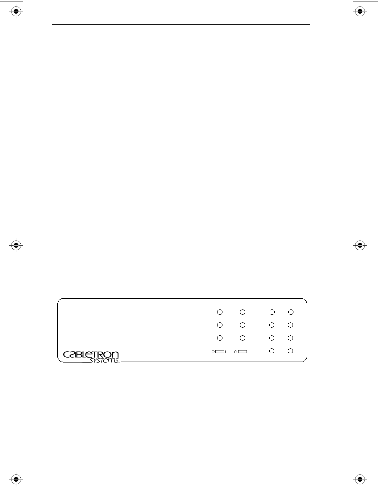
1.3 AN OVERVIEW OF THE MT-800
The MT-800 (Figure 1-1) is an eight port transceiver designed to link
up to eight network or host devices together. The MT-800 allows these
devices to communicate with a network or just between themselves.
The MT-800 is compatible with specifications for a 10 Mb/s Medium
Access Unit under Ethernet Versions 1.0 and 2.0, and IEEE 802.3
standards.
The MT-800 works in two modes - Local or Network. In the Local mode,
the MT-800 only receives and transmits traffic from the devices
attached to it. This mode is enabled by the Loopback (LBK) switch on
the front of the MT-800.
The MT-800 can also be configured with another transceiver to allow
the devices attached to it to communicate with a larger network. The
other transceiver could be attached to a thick or thin coax cable, a fiber
optic link or a twisted pair segment.
The MT-800 contains nine AUI ports. Ports 1-8 connect the MT-800 to
network devices or host units. These eight ports act as transceivers.
The ninth port allows the MT-800 to be connected to an external
transceiver, giving the other devices access to the network.
The MT-800 can also be configured in a cascaded method with a second
layer of MT-800s. Up to eight additional MT-800s could be connected
through one MT-800, allowing up to 64 users.
MT-800
ETHERNET/IEEE 802.3
MULTIPORT TRANSCEIVER UNIT (MAU)
WITH
LANVIEW™
NETWORK LOCAL
PWR
RCV
CP
LBK SQE
PORT
5
6
7
8
T
1
R
A
2
N
S
3
M
I
4
T
Figure 1-1. MT-800
Page 1-8
Page 7

INTRODUCTION
The MT-800 also incorporates Cabletron Systems LANVIEW
diagnostic and monitoring LEDs. Should a physical layer problem
arise, troubleshooting of power failures, collisions, cable faults, or
many other problems can be diagnosed rapidly using these LEDs.
1.4 RELATED USER MANUALS
The manuals identified below should be used to supplement the
procedures and other technical data provided in this manual. The
procedures contained in these manuals will be referenced rather than
repeated in this manual:
Cabletron Systems
Manual.
Cabletron Systems
Cabletron Systems
Cabletron Systems
Manual.
LAN-MD Portable Ethernet Tester
ST-500 Coaxial Transceiver
TPT Twisted Pair Transceiver
FOT-F1 Fiber Optic Transceiver
User's Manual.
User's Manual.
User's
User's
Page 1-9
Page 8

NETWORK REQUIREMENTS/SPECIFICATIONS
CHAPTER 2
NETWORK REQUIREMENTS/SPECIFICATIONS
This chapter contains the network design guidelines, specifications,
power supply requirements, and environmental guidelines for
Cabletron Systems MT-800.
Review all specifications and requirements outlined in this chapter
before you install the MT-800. All outlined conditions must be met to
ensure satisfactory performances of your network.
NOTE:
specifications at any time without notice.
2.1 NETWORK DESIGN GUIDELINES
The following network design guidelines must be followed when
connecting the MT-800 Multiport transceiver to other devices. If not,
unsatisfactory network performance may result.
Cabletron Systems reserves the right to change these
• The transceivers that the MT-800 is connected to must meet
IEEE 802.3 standards.
• The AUI cables connecting the MT-800 to the transceivers on
the network must be IEEE 802.3 type cables.
• The length of the AUI cables attached to the MT-800 is
dependent on the configuration:
a. When one MT-800 is being used in a stand alone
configuration, the total length of any AUI cable from the
MT-800 to a node must not exceed 40 meters (Figure 2-1).
Page 2-11
Page 9

NETWORK REQUIREMENTS/SPECIFICATIONS
M
A
N
N
T
A
M
A
N
T-800
UI Cable
ode
Figure 2-1. MT-800 in Stand Alone Configuration
b. When one MT-800 is being used in the network mode
(Fig. 2-2), the total AUI length, as measured from the
network transceiver to the end device, must not exceed 40
meters.
etwork Segment
ransceiver
UI to Network Port
T-800
UI Segments
ode
Figure 2-2. MT-800 in Network Configuration
c. When an MT-800 in the stand alone mode is cascaded with
another MT-800 (Fig. 2-3), the total AUI length from the
main MT-800 (1) to an end device must not exceed 30
meters.
Page 2-12
Page 10

NETWORK REQUIREMENTS/SPECIFICATIONS
P
A
S
A
N
T
A
P
A
S
A
rimary MT-800
UI Segments
econdary Layer
of MT-800s
UI Segments
Figure 2-3. MT-800 in Stand Alone Cascaded Configuration
d. When an MT-800 in the network configuration is cascaded
with another MT-800 (Fig. 2-4), the total AUI length from
the network transceiver to the end device must not exceed
30 meters.
etwork Segment
ransceiver
UI to Network Port
rimary MT-800
UI Segments
econdary Layer
of MT-800
UI Segments
Figure 2-4. MT-800 in Network Cascaded Configuration
• The MT-800 device can be cascaded up to 2 units deep.
• One MT-800 can support up to 64 users.
Page 2-13
Page 11

NETWORK REQUIREMENTS/SPECIFICATIONS
2.2 SPECIFICATIONS
TRANSMIT
TX-in and TX-out Ports 1-8
Parameter Typical Worst
Value Case
Frequency range: 4-20 MHz 5-15 MHz
Input impedance
differential: 78 ohms 76-80 ohms
common-mode: > 20.0 ohms
Common-mode voltage
range at TX-in: 0-30 Volts 0-5 Volts
Input sensitivity:
100 mV
±
±
Delay time,TX-in (any) to
TX-out
start-up: 50 ns 100 ns
steady-state: 10 ns 20 ns
Waveform
Symmetry TX-out:
±
0.25 ns
±
Output Voltage into
78 ohms TX-out: 900 mV 550 mV
RECEIVE
RX-in and RX-out Ports 1-8
Parameter Typical Worst
Value Case
Frequency range: 4-20 MHz 5-15 MHz
75 to 150 mV
0.50 ns
Input impedance
differential: 78 76-80 ohms
common-mode: > 20.0 ohms
Page 2-14
Page 12

NETWORK REQUIREMENTS/SPECIFICATIONS
RECEIVE (cont.)
RX-in and RX-out Ports 1-8
Parameter Typical Worst
Value Case
Common-mode voltage
range at TX-in: 0-30 Volts 0-5 Volts
Input sensitivity:
100 mV
±
±
Delay time, RX-in to RX-out
start-up: 50 ns 100 ns
steady-state: 10 ns 20 ns
Waveform Symmetry
RX-out (any):
±
0.25 ns
±
Output Voltage into 78
ohms RX-out (any): 900 mV 550 mV
COLLISION DETECTOR
Parameter Typical Worst
Value Case
Output frequency: 10 MHz 9-11 MHz
75 to 150 mV
0.50 ns
Turn-on delay.
CP-in to CP-out (any): 50 ns 150 ns
Turn-off delay: 250 ns 300 ns
Frequency range: 4-20 MHz 5-15 MHz
Input impedance CP-in.
differential: 78 ohms 76-80 ohms
common-mode: > 20.0 ohms
Page 2-15
Page 13

NETWORK REQUIREMENTS/SPECIFICATIONS
COLLISION DETECTOR (cont.)
Parameter Typical Worst
Value Case
Common-mode voltage range
at CP-in: 0-30 Volts 0-5 Volts
Input sensitivity:
±
100 mV
Output Voltage into 78 ohms
CP-out (any): 900 mV 550 mV
Interframe test signal (SQE TEST)
(Switch selectable in LOOPBACK
mode only.)
delay: 700 ns 600-1000 ns
duration: 800 ns 600-1000 ns
±
75 to 150 mV
NOTES
:
1) The MT-800 will generate SQE (10 MHz) at Ports 1-8 if either the
CP-in pair is active or if more than one of the TX-in pairs (Port 1-8) are
active.
2)The MT-800 will generate a JAM signal (5 MHz) on the TX-out pair
whenever more than one of the TX-in pairs (Port 1-8) is active.
INTERFACE CONNECTORS
PORTS 1-8
Type:15 position D type plug.
Pin Pin
1 Logic Ref 9 Collision -
2 Collision + 10 Transmit -
3 Transmit + 11 Logic Ref.
4 Logic Ref. 12 Receive -
5 Receive + 13 N/C
6 N/C 14 Logic Ref.
7 N/C 15 N/C
8 Logic Ref.
Page 2-16
Page 14

NETWORK REQUIREMENTS/SPECIFICATIONS
INTERFACE CONNECTORS (cont.)
NETWORK
Type: 15 position D type receptacle.
Pin Pin
1 Logic Ref. 9 Collision -
2 Collision + 10 Transmit 3 Transmit + 11 Logic Ref.
4 Logic Ref. 12 Receive 5 Receive + 13 Power (+12 Vdc)
6 Power Return 14 Logic Ref.
7 N/C 15 N/C
8 Logic Ref.
INDICATORS
NOTE: The MT-800 has PWR, RCV and CLN LEDs for both the Local
and Network modes.
PWR
Indicates that the MT-800 is receiving power (green
LED).
RCV
Indicates that the MT-800 is receiving a data packet
(orange LED).
CLN
Indicates that a collision has been detected on the
network or local mode (red LED).
NOTE:
TRANSMIT
The MT-800 has a Transmit LED for each AUI port.
Indicates that the port is transmitting data to the other
devices attached to the MT-800 and to the network, if
the network mode is selected (green LED).
Page 2-17
Page 15

NETWORK REQUIREMENTS/SPECIFICATIONS
POWER SUPPLY
Parameter Typical Worst
Value Case
Input Voltage Vac 47-63 Hz.
120 volts 120 Vac 90-130 Vac
220 volts 220 Vac 180-250 Vac
NOTE:
The MT-800 automatically differentiates and selects for the
proper input voltage.
Overload Protection: (2) 3AG 3 Amp fuses in series with
both primary inputs.
Output Voltage Vdc: 12 Vdc11.5-15.5 Vdc
Overload Protection: (1) 3AG 1 Amp fuse.
ENVIRONMENTAL
NOTE:
It is the responsibility of the person who sells the system of
which the MT-800 will be a part of to ensure that the total system meets
the allowed limits of conducted and radiated emissions.
Operating temperature: +5° to +40° C
Non-operating temperature: -30° to +90° C
Operating humidity: 5 to 95% non-condensing
SAFETY
Designed in accordance with UL478, UL910, NEC 725-2(b).Meets
FCC part 15 Class A limits.
Page 2-18
Page 16

NETWORK REQUIREMENTS/SPECIFICATIONS
Isolation: 500 Vac 47-63 Hz Applied between any of the
input ports shields and safety earth ground.
SERVICE
MTBF: 743,373 hrs. projected
MTTR: <.5 hr.
PHYSICAL
Dimensions: 3.2 H x 15.0 W x 12.4 D inches
8.13 x 38.1 x 31.5 cm)
Weight:
Unit: 3 lbs.
Shipping: 4 lbs.
Page 2-19
Page 17

INSTALLATION
CHAPTER 3
INSTALLATION
This chapter outlines the steps for installing the Cabletron Systems
MT-800. Be sure the guidelines and requirements in
Installation Requirements
outlines in
MT-800.
3.1 UNPACKING THE MT-800
Before you install the MT-800, you should check the contents of the
accessory package.
1. Carefully remove the MT-800 from the shipping box.
Chapter 2, Specifications
, and all the specifications and requirements
, are met before installing the
Chapter 3,
2. Remove the MT-800 from the packing material and its protecting
plastic bag. Be sure to save the shipping box in the event the
MT-800 has to be reshipped. Set the transceiver aside to prevent it
form being damaged.
3. Remove the plastic bag containing the accessories and check that it
contains the following items:
One standard 3 prong USA power cord
One Cable Support
Ten Cable Ties
4. Inspect the MT-800. If any damage appears to have occurred, call
Cabletron Systems Technical Support immediately.
3.2 SETTING THE SWITCHES ON THE MT-800
Before installing the MT-800, set the SQE switch, the Loopback switch,
and input power as described below.
3.2.1 Setting the SQE Switch
The
SQE
Test switch (Figure 3-1) allows you to enable or disable the
SQE or “heartbeat” test function. The
switch on the front of the MT-800. The MT-800 is shipped with the SQE
disabled.
SQE
switch is the two position
Page 3-21
Page 18

INSTALLATION
CAUTION: The SQE must not be enabled when the MT-800 is attached
to an IEEE 802.3 compliant repeater or equipment meeting Ethernet
Version 1.0 specifications.
Set the SQE switch as follows, using a pen, small screwdriver or
similar object:
• To enable the SQE test function slide the SQE Switch to the on
position (|), as indicated on the front of the MT-800.
• To disable the SQE test function, slide the SQE switch to the
off position (O), as indicated on the front of the MT-800.
DISABLE ENABLE
SQE
Figure 3-1. SQE Switch
3.2.2 Setting the Loopback Function
The Loopback (LBK) Select switch (Figure 3-2) allows the MT-800 to
be configured for use in the stand alone mode or as part of a larger
network. If the MT-800 will be used in the stand alone mode, the LBK
function must be enabled. The MT-800 is shipped with the loopback
function disabled.
NOTE: SQE function is disabled if the LBK function is disabled
Set the LBK select switch as follows, using a small screwdriver, pen or
similar object:
• To enable loopback function, move the LBK switch to the on (|)
setting.
• To disable loopback function, move the LBK switch to the off
(O) setting.
Page 3-22
Page 19

INSTALLATION
The Loopback function can be enabled if the MT-800 is attached to a
network through the Network Port. With Loopback enabled, the traffic
from the segments attached to Port 1-8 will not be allowed to pass to
the larger network attached to the Network Port.
DISABLE ENABLE
LBK
Figure 3-2. Loopback (LBK) Switch
3.3 INSTALLING THE MT-800
The MT-800 can be installed for use as a stand alone unit or attached
to a network.
NOTE: A location should be selected before installation procedures
begin. The device must be within reach of the AUI cables that will be
attached to it.
3.3.1 Attaching the MT-800 to a Network
The MT-800 is attached to a network through the Network port on the
rear of the Multiport transceiver. If the MT-800 will be used exclusively
in the stand alone mode, and will not be attached to a larger network,
skip these steps and go to Section 3.3.2, Connecting Devices to the
MT-800.
Attach the MT-800 to a network as follows:
1. Attach an AUI cable to the AUI port on the network transceiver.
2. Attach the other end of the AUI cable to the Network Port on the
back of the MT-800.
3. Check that the LBK switch is in the off (0) position.
Page 3-23
Page 20

INSTALLATION
NOTE: The MT-800 can still be used in the stand alone mode when
attached to a network. To do so, enable the loopback function.
4. Attach segments to Ports 1-8 as described below.
3.3.2 Connecting Devices to the MT-800
Up to eight devices can be attached to the MT-800 through the AUI
ports. The devices could be nodes or another MT-800. The MT-800s can
be configured in layers (cascaded) up to two deep.
Connect nodes or another multiport transceiver to your MT-800 as
follows:
NOTE: If the MT-800 will be used in the stand alone mode, be sure the
loopback function is enabled.
1. Connect an AUI cable to a male port (Ports 1-8) on the back of the
MT-800.
2. Connect the AUI cable to the other device.
NOTE: If the device being attached to one of the male ports is another
MT-800, be sure the loopback function is disabled on the second
MT-800.
3. Plug the power cord into the power cord port on the MT-800.
4. Plug the power cord into a standard 3-prong outlet.
The MT-800 will now be receiving power, since it does not have a
power switch.
5. Check that the LEDs are lit under the mode you have selected,
either Network or local. They should be displayed as follows:
The Power (PWR) LED should be on.
If this LED is not lit, check the power cord connections. Unplug
each end and plug it back in.
The RCV and CP LEDs will flash as data is received and
collisions are detected by the MT-800.
Page 3-24
Page 21

INSTALLATION
The TRANSMIT LEDs should flash as the device connected to
that port transmits data.
If the RCV, CP or TRANSMIT LEDs fail to flash, disconnect the
respective AUI cable, check the connections and reattach the cable.
If the LEDs still fail to light, contact Cabletron Systems Technical
Support.
6. Strain relief the cables attached to the MT-800.
Your MT-800 is now ready for operation. It is recommended that the
system be tested prior to transmitting data, using the steps outlined in
Chapter 4, Testing and LANVIEW.
Page 3-25
Page 22

TESTING AND LANVIEW
CHAPTER 4
TESTING AND LANVIEW
This chapter outlines procedures to check that the MT-800 Multiport
Transceiver is properly connected to your network and is functioning
properly.
Instructions are provided for using Cabletron Systems LANVIEW to
troubleshoot network problems on the physical layer.
4.1 INSTALLATION CHECKOUT
This section contains procedures to test the MT-800 after it has been
installed onto your network to ensure that the physical layer of the
network is operating properly.
For the procedures in this section, you will need:
• If the MT-800 is being used in the network mode, two Ethernet
testers capable of generating valid data packets are needed,
such as Cabletron Systems LAN-Specialist or LAN-MD.
• If the MT-800 is being used in the local mode, one Ethernet
tester capable of generating valid data packets is needed, such
as Cabletron Systems LAN-Specialist or LAN-MD.
NOTE: Steps 1, 2 and 3 are performed for both local or network mode.
The procedures under step 5 are performed only if the MT-800 is
attached to a network. The test procedures should be repeated for
Ports 1-8.
1. Disconnect the AUI cable from one of the devices attached to the
MT-800.
2. Using the AUI cable, connect a LAN-Specialist to the MT-800.
Page 4-27
Page 23

TESTING AND LANVIEW
LAN-MD
AUI Cable
MT-800
Figure 4-1 Checkout Configuration
3. Select 6 - SERVER on the LAN-Specialist and run the test. Verify
that this test passes.
• The status on the LAN-Specialist should read 000, and a pass
LED should be lit on the LAN-Specialist.
• This LAN-Specialist now acts as the SERVER unit and will act
as a packet echoer when used with another LAN-Specialist.
4. Repeat these steps for each port, 1-8.
5. If the MT-800 will be connected to a network, use the following
checkout procedures:
a. Using an AUI cable, attach the other LAN-Specialist to a
properly functioning transceiver elsewhere on the network.
b. Select 4 - NODE on the second LAN-Specialist and run the
test. Verify that this test passes.
• At least 100 packets should be sent and received with no errors.
The packets will be received and sent back from the SERVER
LAN-Specialist that was left running on the other segment.
• If this test fails, check that the tap connections are made
properly.
c. Repeat these steps for Ports 1-8 on the MT-800.
Page 4-28
Page 24

TESTING AND LANVIEW
When each port on the MT-800 Multiport Transceiver successfully
completes this test, the unit is ready for operation. If any failures were
noted, please contact Cabletron Systems Technical Support.
4.2 USING LANVIEW
The MT-800 Multiport Transceiver uses Cabletron Systems built-in
visual diagnostic and monitoring system, LANVIEW. LANVIEW
LEDs allow a troubleshooter to quickly diagnose network problems and
determine which node or segment is faulty.
The following discusses the function and purpose of each LANVIEW
LED on the MT-800.
Transmit (TRANSMIT) LED
This green LED flashes when a data packet is being transmitted
through the respective port. The flash of the LED is pulse stretched for
viewing effect.
These LEDs are only lit if an active segment is attached to that port
and the device on that AUI is transmitting data.
NOTE: PWR, RCV and CP LEDs are installed for both the Network
and Local modes. These LEDs are only lit under the mode which is
selected with the LBK switch.
Power (PWR) LED
When lit, this green LED indicates that the MT-800 is receiving power.
If this LED is not lit, the problem may be with the input power or the
MT-800.
Receive (RCV) LED
This orange LED normally flashes on and off to indicate the MT-800 is
receiving a data packet from:
• node attached to the MT-800, if the loopback mode is enabled
• node or the network if the network mode is enabled.
The flash of the LED is pulse stretched for viewing effect.
Page 4-29
Page 25

TESTING AND LANVIEW
Collision Present (CLN) LED
This red LED flashes to indicate a collision has been detected.
If the MT-800 is in the network mode, collisions are detected on the
network or the AUI segments attached to the MT-800.
If the MT-800 is in the loopback mode, collisions are only detected on
the segments attached to Ports 1-8.
The flash of the LED is pulse stretched for viewing effect.
Page 4-30
 Loading...