

Page 1

MRX/MRX-2 AND
MRXI/MRXI-2
10BASE-T HUB
INSTALLATION GUIDE
CABLETRON SYSTEMS, P.O. Box 5005, Rochester, NH 03867-5005
INC.
The Complete Networking Solution
Page 2

NOTICE
NOTICE
Cabletron Systems reserves the right to make changes in
specifications and other information contained in this document
without prior notice. The reader should in all cases consult Cabletron
Systems to determine whether any such changes have been made.
The hardware, firmware, or software described in this manual is
subject to change without notice.
IN NO EVENT SHALL CABLETRON SYSTEMS BE LIABLE FOR
ANY INCIDENTAL, INDIRECT, SPECIAL, OR CONSEQUENTIAL
DAMAGES WHATSOEVER (INCLUDING BUT NOT LIMITED TO
LOST PROFITS) ARISING OUT OF OR RELATED TO THIS
MANUAL OR THE INFORMATION CONTAINED IN IT, EVEN IF
CABLETRON SYSTEMS HAS BEEN ADVISED OF, KNOWN, OR
SHOULD HAVE KNOWN, THE POSSIBILITY OF SUCH
DAMAGES.
© Copyright March 1991 by:
Cabletron Systems, Inc.
P.O. Box 5005, Rochester, NH 03867-5005
All Rights Reserved
Printed in the United States of America
Order number: 9030313 March 91
MRX, MRX-2, MRXI, MRXI-2, LANVIEW, SPIM-T, SPIM-T1,
TMS-3, FOT-F, TPT-T, SPIM-F1, SPIM-F2, SPIM-C, SPIM-A,
Remote LANVIEW/Windows, SPECTRUM, and LAN-MD are
trademarks of Cabletron Systems, Inc.
i
Page 3

FCC NOTICE
FCC NOTICE
This device complies with Part 15 of FCC rules. Operation is subject
to the following two conditions: (1) this device may not cause harmful
interference, and (2) this device must accept any interference received, including interference that may cause undesired operation.
WARNING: This equipment uses and generates and can radiate
radio frequency energy and if not installed properly and used in
accordance with the instruction manual, may cause interference to
radio communications. It has been tested and found to comply with
the limits for a Class A digital device pursuant to Part 15 of FCC
Rules, which are designed to provide reasonable protection against
such interference in a commercial environment. Operation of this
equipment in a residential area is likely to cause interference in
which case the user at his own expense will be required to take
whatever steps may be necessary to correct the interference.
If this equipment does cause interference to radio or television,
which can be determined by turning the equipment off and on, the
user is encouraged to try to correct the interference by one or more of
the following measures:
• Re-orient the receiving antenna.
• Relocate the antenna with respect to the MRX/MRXI.
• Move the MRX/MRXI away from the antenna.
• Plug the MRX/MRXI into a different outlet so that the
MRX/MRXI and the receiver are on different branch circuits.
If necessary, the user should consult the dealer or an experienced
radio/ television technician for additional suggestions. The user may
find the following booklet prepared by the Federal Communication
Commission helpful:
“How to Identify and Resolve Radio TV Interference Problems”
This booklet is available from the U.S. Government Printing Office,
Washington D.C. 20402 - Stock No. 004-000-00345-4.
ii
ii
Page 4

CONTENTS
CONTENTS
CHAPTER 1 INTRODUCTION
1.1 Using This Manual ..................................................................... 1-2
1.2 The 10BASE-T HUB................................................................... 1-2
1.3 Related Manuals ......................................................................... 1-4
1.4 Getting Help................................................................................ 1-4
CHAPTER 2 INSTALLATION REQUIREMENTS/
SPECIFICATIONS
2.1 Network Requirements............................................................... 2-1
2.2 Selecting A Location For The HUB............................................ 2-1
2.3 Network Guidelines .................................................................... 2-2
2.3.1 10BASE-T Twisted Pair Network Requirements ........... 2-2
2.3.2 Fiber Optic Network Requirements ................................ 2-4
2.3.3 Thin-Net Network Requirements .................................... 2-4
2.3.4 Transceiver/AUI Requirements ....................................... 2-5
2.4 Operating Specifications............................................................. 2-6
CHAPTER 3 INSTALLATION
3.1 Unpacking The HUB .................................................................. 3-1
3.2 Attaching The Strain Relief Bracket ......................................... 3-2
3.3 Installing The HUB .................................................................... 3-2
3.3.1 Rack Mounting The HUB ................................................ 3-2
3.3.2 Wall Mounting The HUB ................................................. 3-4
3.3.3 Free-Standing Installation .............................................. 3-7
3.4 Connecting The HUB To The Power Source.............................. 3-7
3.5 Connecting The HUB To The Ethernet Network...................... 3-8
3.5.1 Connecting The Network Port Cabling (MRX/MRXI).....3-8
3.5.2 Connecting The Network Port Cabling
(MRX-2/MRXI-2)............................................................... 3-8
3.5.3 Connecting A Twisted Pair Segment To A SPIM-T ........ 3-9
3.5.4 Connecting A Shielded Twisted Pair Segment
To A SPIM-T1 ................................................................. 3-10
iii
Page 5

CONTENTS
CONTENTS (cont.)
CHAPTER 3 (cont.)
3.5.5 Connecting A Fiber Optic Link Segment To A
SPIM-F1Or SPIM-F2 ..................................................... 3-11
3.5.6 Connecting A Thin-Net Segment To A SPIM-C............ 3-14
3.5.7 Connecting An AUI Cable To A SPIM-A.......................3-15
3.6 Finishing The Installation........................................................ 3-16
CHAPTER 4 TESTING AND TROUBLESHOOTING
4.1 Installation Check-Out ............................................................... 4-1
4.2 Testing Segments Attached To The HUB.................................. 4-2
4.3 Using LANVIEW ........................................................................ 4-5
CHAPTER 5 ADDING/REPLACING SPIMs
5.1 Opening The HUB ...................................................................... 5-1
5.2 Removing A SPIM....................................................................... 5-2
5.3 Installing A SPIM ....................................................................... 5-2
APPENDIX TWISTED PAIR WIRING GUIDE
A.1 Attaching Twisted Pair Segments To The HUB ...................... A-1
iv
Page 6

INTRODUCTION
CHAPTER 1
INTRODUCTION
Welcome to the Cabletron Systems MRX/MRX-2 and MRXI/MRXI-2
10BASE-T HUB Installation Guide. This manual covers
installation instructions and provides reference information for the
following Cabletron Systems 10BASE-T Hubs:
• MRX
- 12-10BASE-T (using 50-pin Champ connector)
- 2 Single Port Interface Module (SPIM) slots
- No Management
• MRX-2
- 12-10BASE-T (using RJ-45 connectors)
- 2 Single Port Interface Module (SPIM) slots
- No Management
• MRXI
- 12-10BASE-T (using 50-pin Champ connector)
- 2 Single Port Interface Module (SPIM) slots
- SNMP Compliant Management
• MRXI-2
- 12-10BASE-T (using RJ-45 connectors)
- 2 Single Port Interface Module (SPIM) slots
- SNMP Compliant Management
NOTE: The term HUB is used throughout this manual when
describing features and functions that are common to all of the devices
listed above. The terms MRX, MRX-2, MRXI and MRXI-2 are only
used when it is necessary to describe features that are unique to a
specific device.
All four HUBs can serve as a repeater to allow expansion of existing
802.3 networks using a variety of media. All four HUBs are
10BASE-T and 802.3 compliant.
Page 1-1
Page 7

INTRODUCTION
The MRX is functionally identical to the MRX-2 and the MRXI is
functionally identical to the MRXI-2. The MRX and MRXI provide a
50-pin Champ connector for ports 1 through 12, and the MRX-2 and
MRXI-2 provide twelve RJ-45 connectors.
The MRX/MRX-2 and MRXI/MRXI-2 are functionally the same,
except that the MRXI/MRXI-2 provides the capability of in-band and
out-of-band network management. The MRX/MRX-2 is not
accessible, either in-band or out-of-band, by network management.
1.1 USING THIS MANUAL
Prior to installing and operating the HUB, read through this manual
completely to familiarize yourself with its content and to gain an
understanding of the features of the HUB. A general working
knowledge of Ethernet and IEEE 802.3 type data communications
networks and their physical layer components will be helpful when
installing the HUB.
Chapter 1, Introduction, covers using this document, briefly
describes features of the HUB and concludes with a list of related
manuals.
Chapter 2, Requirements/Specifications, contains requirements
for locating and installing the HUB and operating specifications for
the MRX and MRXI.
Chapter 3, Installation, contains step-by-step installation
instructions that include mounting and cabling for your HUB.
Chapter 4, Testing and Troubleshooting, contains procedures for
checking for the proper installation of the HUB and a description of
the LANVIEW ™ LEDs and their function.
Chapter 5, Adding/Replacing SPIMs, describes removing and
installing optional SPIM boards in the HUB.
Appendix, Twisted Pair Wiring Guide, serves as an aid to wiring
punch-down blocks and twisted pair segments between your HUB
and 10Base-T Ethernet devices.
Page 1-2
Page 8
INTRODUCTION
1.2 THE 10BASE-T HUB
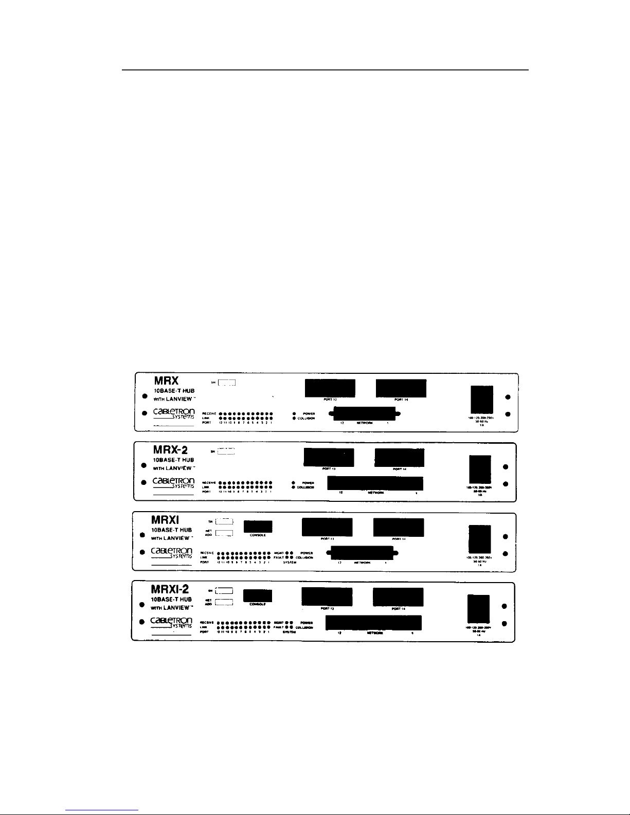
The Cabletron Systems HUB provides twelve 10BASE-T compliant
ports (via 50 pin Champ connector) and two slots that support
Cabletron Systems’ Single Port Interface Modules (SPIM). A variety
of SPIMs are available permitting the expansion of an Ethernet/802.3
network via:
• Unshielded Twisted Pair Cable from the 10BASE-T Twisted Pair
Interface Modules (SPIM-T).
• Shielded Twisted Pair Cable from the 10BASE-T Twisted Pair
Interface Modules (SPIM-T1).
• Fiber Optic Cable, with SMA or ST connectors, from the Fiber
Optic Interface Modules (SPIM-F1 or SPIM-F2).
• Thin-Net Cable from the Coaxial Interface Module (SPIM-C).
• AUI Cable, to an external transceiver, from the AUI Interface
Module (SPIM-A).
Figure 1-1. MRX, MRX-2, MRXI and MRXI-2 10BASE-T HUBs
Page 1-3
Page 9

INTRODUCTION
The HUB fully conforms to the IEEE 802.3 Repeater, AUI and
10BASE-T specifications, and provides the flexibility to connect
networks using IEEE 802.3, Ethernet Version 1 or Version 2
equipment. As an IEEE 802.3 compliant repeater, the HUB
transmits re-timed data packets, regenerates the preamble, extends
fragments, arbitrates collisions and automatically partitions problem
segments, and reconnects non-problem segments. This feature
minimizes the impact on network operation resulting from a problem
on one segment by isolating the problem segment so that only the
devices on that segment are affected. When the problem is solved, the
problem segment is automatically reconnected to the network.
Since the HUB utilizes polarity detection and correction, the twisted
pair connections are not sensitive to signal polarity. The network will
still function properly with the (+) and (–) lines within a pair
reversed. The LINK LED for the port with reversed polarity will
flash to indicate this condition. Operating in this condition is not
recommended and if this condition is discovered, the segment should
be removed from the network and wired correctly by a technician.
This reduces the potential for problems in the future if equipment
changes are made. Connector pinouts are provided in Chapter 2,
Installation Requirements/Specifications.
All four HUBs incorporate Cabletron Systems’ LANVIEW™ status
monitoring and diagnostic system. LANVIEW is a convenient
troubleshooting tool that allows you to monitor power, and data
activity and help you diagnose power failures, collisions, cable faults,
and link problems.
The MRXI provides an RS-232 Console port (not available in the
MRX) that supports a Digital Equipment Corporation™, VT220™ or
PC emulation of the VT220™ terminal. The terminal serves as a
local management console, providing out-of-band access to MRXI/
LM™, Local Management for the Cabletron Systems MRXI/MRXI-2.
MRXI/LM is an effective menu driven tool that presents screens that
integrate network status and network control. Several menus permit
the network manager to manage and monitor the flow of traffic and
access a summary of errors to pinpoint potential problem areas in a
network. This capability gives the network manager the ability to
interpret status and establish parameters to obtain optimal
performance for the network and, if necessary, permit diagnosis of
network problems. For additional information, refer to the
MRXI/LM, Local Management for the Cabletron Systems
MRXI/MRXI-2, User’s Manual.
Page 1-4
Page 10

INTRODUCTION
The MRXI/MRXI-2 can also be controlled and managed in-band using
Cabletron Systems’ LANVIEW/Windows, SPECTRUM, and SNMP
network control management software.
1.3 RELATED MANUALS
The manuals listed below should be used to supplement the
procedures and other technical data provided in this manual. The
procedures contained in these manuals will be referenced where
appropriate, rather than repeated.
MRXI/LM, Local Management for the Cabletron Systems
MRXI/MRXI-2, User’s Manual.
Cabletron Systems’ LAN-MD Portable Ethernet Tester User’s
Manual.
1.4 GETTING HELP
If additional support is needed related to the Cabletron Systems
HUB, or if you have any comments, suggestions, or questions relating
to this manual contact Cabletron Systems Technical Support at:
Cabletron Systems, Inc.
P.O. Box 5005
Rochester, NH 03867-5005
Phone: (603) 332-9400
Page 1-5
Page 11

INTRODUCTION
Page 1-6
Page 12

REQUIREMENTS/SPECIFICATIONS
CHAPTER 2
INSTALLATION
REQUIREMENTS/SPECIFICATIONS
This Chapter describes the network and power requirements and
operating specifications for the MRX, MRX-2, MRXI, and MRXI-2
10BASE-T HUBs. Before you attempt to install any of these HUBs,
review the installation requirements and operating specifications
that are outlined in this chapter. Your network installation must
meet the conditions, guidelines, specifications, and requirements
included in this chapter to obtain satisfactory performance from this
equipment. Failure to follow these guidelines could produce poor
network performance.
2.1 NETWORK REQUIREMENTS
Take care in planning and preparing the cabling and connections for
your network. The quality of the connections, the length of cables
and other conditions of the installation are critical factors in
determining the reliability of your network. The following sections
describe the network requirements to operate this equipment.
2.2 SELECTING A LOCATION FOR THE HUB
The HUB can be rack mounted, wall mounted, or placed on any
horizontal surface. If not installed in a 19-inch rack, the following
requirements must be met when selecting a location for your HUB.
NOTE: Be sure that the location selected is within reach of the
network cabling.
• An unrestricted free surface area 21 inches wide, 18 inches deep
and 6 inches high is needed.
• A single phase 120 Vac, 15A, grounded power receptacle must be
located within 7 feet of the site.
Page 2-1
Page 13

REQUIREMENTS/SPECIFICATIONS
• If a shelving unit is to be used, it must be able to support
30 pounds of static weight.
• The temperature for the selected location must be maintained
between 5° and 50° C, and less than 10° C per hour temperature
change.
2.3 NETWORK GUIDELINES
The following network design guidelines must be followed when
connecting the HUB to your network:
• As a general rule, 130 meters is the maximum length for an
unshielded twisted pair segment. However, losses introduced by
connections at punch-down blocks and other equipment serve to
reduce this limit. In most installations, the optimal unshielded
twisted pair length is 100 meters using standard PVC phone wire.
Maximum link length is largely dependent on cable quality. If
high quality, low attenuation cable is used, link lengths of up to
200 meters are achievable.
• The device at the other end of the twisted pair segment must
meet IEEE 802.3 10BASE-T specifications.
• The transceivers that will be connected to the HUB (via a
SPIM-A) must meet IEEE 802.3 standards and must not have the
SQE test function enabled.
2.3.1 10BASE-T Twisted Pair Network Requirements
When connecting a 10BASE-T Twisted Pair Segment at any of the
10BASE-T Twisted Pair HUB Ports (Ports 1 through 12, a Single Port
10BASE-T Twisted Pair Segment Interface module [SPIM-T or
SPIM-T1]), the following network requirements must be met:
• Length - The IEEE 802.3 10BASE-T standard requires that
10BASE-T devices transmit over a 100 meter (328 foot) link using
22-24 AWG unshielded twisted pair wire.
Page 2-2
Page 14

REQUIREMENTS/SPECIFICATIONS
As a general rule, links up to 130 meters in length for unshielded
twisted pair and 200 meters in length for shielded twisted pair
are achievable. For each connector or patch panel in the link,
subtract 12 meters from the 150 meter limit. This will allow for
links of up to 126 meters using standard 24 AWG UTP wire and
two patch panels within the link. Higher quality low attenuation
cables may be required when using links of greater than 126
meters. Due to cable delay, the maximum link length is always
limited to 200 meters, regardless of the cable type.
• Insertion Loss - The maximum insertion loss allowed for a
10BASE-T link is 11.5 dB at all frequencies between 5.0 and 10
MHz. This includes the attenuation of the cables, connectors,
patch panels, and reflection losses due to impedance mismatches
in the link segment.
• Impedance - Unshielded twisted pair cables typically have an
impedance of between 85 to 110 ohms. Shielded twisted pair
cables, such as IBM Type 1 cable, can also be used. You should
remember that the impedance of IBM Type 1 cable is typically
150 ohms. This increases the signal reflection caused by the
cable, but since the cable is shielded, this signal reflection has
little effect on the received signal’s quality due to the lack of
crosstalk between the shielded cable pairs. Cabletron Systems’
10BASE-T Twisted Pair products will work on twisted pair cable
with 75 to 165 ohms impedance.
• Jitter - Intersymbol interference and reflections can cause jitter
in the bit cell timing, resulting in data errors. A 10BASE-T link
must not generate more than 5.0 nsec. of jitter. If your cable
meets the impedance requirements for a 10BASE-T link, jitter
should not be a concern.
• Delay - The maximum propagation delay of a 10BASE-T link
segment must not exceed 1000 nsec. This 1000 nsec. maximum
delay limits the maximum link segment length to no greater than
200 meters.
• Crosstalk - Crosstalk is caused by signal coupling between the
different cable pairs contained within a multi-pair cable bundle.
10BASE-T transceivers are designed so that the user does not
need to be concerned about cable crosstalk, provided the cable
meets all other requirements.
Page 2-3
Page 15

REQUIREMENTS/SPECIFICATIONS
• Noise - Noise can be caused by either crosstalk or externally
induced impulses. Impulse noise may cause data errors if the
impulses occur at very specific times during data transmission.
Generally, the user need not be concerned about noise. If noiserelated data errors are suspected, it may be necessary to either
reroute the cable or eliminate the source of the impulse noise.
• Temperature - Multi-pair PVC 24 AWG telephone cables
typically have an attenuation of approximately 8 to 10 dB/100 m
at 20° C (78° F). The attenuation of PVC insulated cable varies
significantly with temperature. At temperatures greater than
40° C (104° F), it is strongly recommended that you use plenumrated cables to ensure that cable attenuation remains within
specification.
2.3.2 Fiber Optic Network Requirements
When connecting a Fiber Optic Link Segment to the HUB with a
Single Port Fiber Optic Interface module (SPIM-F1 or SPIM-F2), the
following network requirements must be met:
• Cable Type - The SPIM-F1 and SPIM-F2 are designed for use
with one of the following multimode fiber optic media:
- 50/125 µm fiber optic cabling.
- 62.5/125 µm fiber optic cabling.
- 100/140 µm fiber optic cabling.
• Attenuation - The fiber optic cable must be tested with a fiber
optic attenuation test set that is adjusted for an 850 nm
wavelength. This test verifies that the signal loss in a cable is
within an acceptable level:
- 13.0 dB or less for 50/125 fiber cable segment.
- 16.0 dB or less for 62.5/125 fiber cable segment.
- 19.0 dB or less for 100/140 fiber cable segment.
Page 2-4
Page 16

REQUIREMENTS/SPECIFICATIONS
• Budget and Propagation Delay - When determining the
maximum fiber optic cable length, the fiber optic budget delay
and total network propagation should be calculated and taken
into consideration before fiber optic cable runs are incorporated in
any network design. Fiber optic budget is the combination of the
optical loss due to the fiber optic cable, in-line splices, and fiber
optic connectors. Propagation delay is the amount of time it takes
a packet to travel from the sending device to the receiving device.
• Length - The maximum allowable fiber optic cable length is 2
km. However, IEEE 802.3 specifications allow for a maximum of
1 km.
2.3.3 Thin-Net Network Requirements
When connecting a Thin-net segment to the HUB with a Single Port
Coax Interface Module (SPIM-C), the following network requirements
must be met:
• Cable Type - 50 ohm RG-58A/U type coaxial cable must be used
when making up a thin-net cable segment.
• Length - The thin-net segment must be no longer than
185 meters.
• Terminations - A 50 ohm terminator must be connected to the
far end of each thin-net segment.
• Connections - A maximum of 29 tee-connectors may be used
throughout the length of cable segment for host connections. If
an excessive number of barrel connectors are used within the
cable segment, such as finished wall plates with BNC feedthroughs, then a reduced number of host connections may be
required. For special network design, contact Cabletron Systems
Technical Support.
• Grounding - For safety, only one end of a thin-net segment
should be connected to earth ground. Connection to earth ground
at more than one point on the segment could produce dangerous
ground currents.
Page 2-5
Page 17

REQUIREMENTS/SPECIFICATIONS
WARNING: Do not connect the shield at both ends of a thin net
segment to ground. Only one end of the shield should be connected
to earth ground.
The BNC ports of the Coaxial Interface Modules are not
connected to earth ground.
2.3.4 Transceiver/AUI Requirements
When connecting an external network segment, via a transceiver and
an AUI cable, to the HUB with a Single Port AUI Interface module
(SPIM-A), the following network requirements must be met:
• Transceiver/Ethernet Device - The transceiver or Ethernet
Device to which the module will be connected must meet IEEE
802.3 standards, and/or Ethernet Version 1.0 or Version 2.0
requirements.
• AUI Cable - The AUI cable connecting the module to a device
must be IEEE 802.3 type cable.
• Length - The AUI Cable must not exceed 50 meters in length. If
28 AWG thin office drop AUI cable is used, then the maximum
cable length is limited to 50 feet (15.24 meters).
Page 2-6
Page 18

REQUIREMENTS/SPECIFICATIONS
2.4 OPERATING SPECIFICATIONS
The operating specifications for the Cabletron Systems’ HUB are
described in this section. Cabletron Systems reserves the right to
change these specifications at any time without notice.
GENERAL
MRXI/MRXI-2 Only
Packet Buffer Memory (RAM): 64 KB
Internal Processor: Intel 80186 operating at 10 MHz
Ethernet Controller: National Semiconductor DP8390
Static RAM: 128 KB
EPROM: 256 KB
MRX/MRX-2 and MRXI/MRXI-2
Delay Times: In Out Delay Typ.
Start of Packet: Twisted Pair SPIM 1000 nsec.
Twisted Pair Twisted Pair 1000 nsec.
SPIM SPIM 1300 nsec.
SPIM Twisted Pair 1300 nsec.
JAM: Twisted Pair SPIM 700 nsec.
Twisted Pair Twisted Pair 700 nsec.
SPIM Twisted Pair 1000 nsec.
Preamble:
Input: Minimum of 20 bits required.
Output: 64 bits min. (last 2 bits are 1, 1).
JAM Output: Collisions are propagated through the
network using the JAM signal of an
alternating pattern of 1’s and 0’s in
accordance with 802.3 specifications for
a repeater unit.
Page 2-7
Page 19

REQUIREMENTS/SPECIFICATIONS
Fragment Packet fragments are extended to a
Extension: minimum of 96 bits using the JAM [1,0].
Fault Protection: Each segment will disconnect itself from
the other segments if 33 consecutive
collisions occur, or if the collision detector
of a segment is on for longer than
approximately 210 µs. This fault
protection will reset automatically after
one packet is transmitted/received onto
the fault protected segment without
causing a collision.
INTERFACE CONNECTORS
Network (Twisted Pair) Interface (Ports 1 through 12)
Internal Transceiver: Cabletron Systems TPT-T Transceiver.
For further information, refer to the
TPT-T Twisted Pair Transceiver User’s
Manual.
MRX/MRXI
Type: 50-Pin Champ Connector
Pin Signal Wire Color Pin Signal Wire Color
1 RX1– Blue/White 26 RX1+ White/Blue
2 TX1– Orange/White 27 TX1+ White/Orange
3 RX2– Green/White 28 RX2+ White/Green
4 TX2– Brown/White 29 TX2+ White/Brown
5 RX3– Gray/White 30 RX3+ White/Gray
6 TX3– Blue/Red 31 TX3+ Red/Blue
7 RX4– Orange/Red 32 RX4+ Red/Orange
8 TX4– Green/Red 33 TX4+ Red/Green
9 RX5– Brown/Red 34 RX5+ Red/Brown
10 TX5– Gray/Red 35 TX5+ Red/Gray
11 RX6– Blue/Black 36 RX6+ Black/Blue
12 TX6– Orange/Black 37 TX6+ Black/Orange
13 RX7– Green/Black 38 RX7+ Black/Green
14 TX7– Brown/Black 39 TX7+ Black/Brown
Page 2-8
Page 20

REQUIREMENTS/SPECIFICATIONS
Pin Signal Wire Color Pin Signal Wire Color
15 RX8– Gray/Black 40 RX8+ Black/Gray
16 TX8– Blue/Yellow 41 TX8+ Yellow/Blue
17 RX9– Orange/Yellow 42 RX9+ Yellow/Orange
18 TX9– Green/Yellow 43 TX9+ Yellow/Green
19 RX10– Brown/Yellow 44 RX10+ Yellow/Brown
20 TX10– Gray/Yellow 45 TX10+ Yellow/Gray
21 RX11– Blue/Violet 46 RX11+ Violet/Blue
22 TX11– Orange/Violet 47 TX11+ Violet/Orange
23 RX12– Green/Violet 48 RX12+ Violet/Green
24 TX12– Brown/Violet 49 TX12+ Violet/Brown
25 N/C Gray/Violet 50 N/C Violet/Gray
Network (Twisted Pair) Interface (Ports 1 through 12)
MRX-2/MRXI-2
Type: Internally Crossed Over RJ-45 Jack (12)
Pin 1 RX+ Pin 5 No Connection
2 RX- 6 TX3 TX+ 7 No Connection
4 No Connection 8 No Connection
ETHERNET PORT - SPIM-T
(10BASE-T TWISTED PAIR PORT)
Internal Transceiver: Cabletron Systems’ TPT-T™ 10BASE-T
Twisted Pair Transceiver
Type: Internally Crossed Over RJ-45 Jack
Pin 1 RX+ Pin 5 No Connection
2 RX- 6 TX3 TX+ 7 No Connection
4 No Connection 8 No Connection
Page 2-9
Page 21

REQUIREMENTS/SPECIFICATIONS
ETHERNET PORT - SPIM-T1
(10BASE-T TWISTED PAIR PORT)
Internal Transceiver: Cabletron Systems’ TPT-T 10BASE-T
Twisted Pair Transceiver
Type: DB-9 Port
Pin 1 TX+ Pin 5 RX-
2 No Connection 6 TX3 No Connection 7 No Connection
4 No Connection 8 No Connection
9 RX+
ETHERNET PORT - SPIM-F1 OR SPIM-F2
(FIBER OPTIC PORT)
Internal Transceiver: Cabletron Systems’ FOT-F™
Fiber Optic Transceiver
Type:
SPIM-F1: SMA fiber optic ports.
SPIM-F2: ST fiber optic ports.
Worst
Parameter Typical Worst Case Typical
Value Value Budget Budget
Receive
Sensitivity: -30.5 dBm -28.0 dBm — —
Peak Input
Power: -7.6 dBm -8.2 dBm — —
Transmitter Power
50/125 µm fiber: -13.0 dBm -15.0 dBm 13.0 dB 17.5 dB
62.5/125 µm fiber: -10.0 dBm -12.0 dBm 16.0 dB 20.5 dB
100/140 µm fiber: -7.0 dBm -9.0 dBm 19.0 dB 23.5 dB
Error Rate: Better than 10
Page 2-10
-10
Page 22

REQUIREMENTS/SPECIFICATIONS
NOTE: The transmitter power levels and receive sensitivity levels
given above are Peak Power Levels after optical overshoot. A Peak
Power Meter must be used to correctly compare the values given above
to those measured on any particular port. If Power Levels are being
measured with an Average Power Meter, then 3 dBm must be added to
the measurement to correctly compare those measured values to the
values listed above (i.e. -30.5 dBm peak=-33.5 dBm average).
ETHERNET PORT - SPIM-C (BNC PORT)
Internal
Transceiver: Cabletron Systems’ TMS-3™ Transceiver.
Termination: The port on the module can be internally
terminated, to an internal 50 Ohm
terminator, utilizing the switch located to
the left of the port. This eliminates the
need to connect the port to a Tee
Connector and terminator.
Type: BNC receptacle, with gold center contact,
for use with BNC type tee-connectors and
RG-58 thin-net cable.
Grounding: For safety, only one end of a thin-net
segment should be connected to earth
ground. Connection to earth ground at
more than one point on the segment may
allow for the occurrence of dangerous
ground currents.
The BNC port of the Coaxial Interface
Modules is not connected to earth ground.
Page 2-11
Page 23

REQUIREMENTS/SPECIFICATIONS
ETHERNET PORT - SPIM-A (AUI PORT)
Interface Connector: DB15 Port
Type: 15 position D type receptacle
Pin 1 Logic Ref. Pin 9 Collision -
2 Collision + 10 Transmit 3 Transmit + 11 Logic Ref.
4 Logic Ref. 12 Receive 5 Receive + 13 Power (+12 Vdc)
6 Power Return 14 Logic Ref.
7 No Connection 15 No Connection
8 Logic Ref.
Connector Shell: Protective Ground
CONSOLE PORT (MRXI/MRXI-2 Only)
The Console (RS-232) Port supports access to Remote LANVIEW
via a Local Management Console connected at the front panel of
the MRXI/MRXI-2. The console port supports a Digital
Equipment Corporation, VT220™ terminal or PC emulation of
the VT220™ terminal.
Type: 9-pin (DB-9) RS232 Port
Pin 1 Carrier Detect (CD) Pin 6 Not Used
2 Transmit Data (TX) 7 Request to Send (RTS)
3 Receive Data (RX) 8 Clear to Send (CTS)
4 Data Terminal Ready (DTR) 9 Ring Indicator (RI)
5 Signal Ground (SG)
Page 2-12
Page 24

REQUIREMENTS/SPECIFICATIONS
INDICATORS
POWER Indicates that the repeater is receiving
(green) power.
LINK Indicates that a link has been established
(green) between the module and the 10BASE-T
device at the other end of the twisted pair
segment. This LED remains lit as long as
the link is maintained. (The LINK LED
flashes to indicate that the HUB has
established a link with reversed polarity.)
RECEIVE Indicates that the repeater is receiving a
(yellow) data packet on that segment.
COLLISION Indicates that a collision is occurring on
(red) a system level.
MGMT Flashes to indicate that the Remote
(yellow) LANVIEW Network Control Management
(MRXI/MRXI-2 only) for the MRXI/MRXI-2 is receiving a packet
directed towards management.
FAULT Indicates an error has been detected by
(red) the MRXI/MRXI-2 software.
(MRXI/MRXI-2 only)
POWER SUPPLY REQUIREMENTS
NOTE: The HUB has a universal power supply. This unit allows
you to use an input power from 85 to 264 VAC, 47-63 Hz.
Parameter Typical Value Worst Case
Input Current:
MRX/MRX-2 0.5 amp 0.75 amp
MRXI/MRXI-2 0.75 1.0
Overload Protection -
Output: (1) 2AG 1 amp fuse.
Page 2-13
Page 25

REQUIREMENTS/SPECIFICATIONS
ENVIRONMENTAL REQUIREMENTS
Operating Temperature: +5° to +50° C
Non-operating
Temperature: -30° to +90° C
Operating Humidity: 5 to 95% (non-condensing)
SAFETY
Designed in accordance with UL478, UL910, NEC 725-2(b), CSA,
IEC, TUV, VDE class A. Meets FCC part 15, Class A limits.
WARNING: It is the responsibility of the person who sells the
system to which the HUB will be a part to ensure that the total
system meets allowed limits of conducted and radiated emissions.
SERVICE
MTBF (MHBK-217D):
MRX/MRX-2 > 132,046 hrs. projected
MRXI/MRXI-2 > 88,610 hrs. projected
MTTR: < 0.5 hr.
PHYSICAL
Dimensions: 3.2H x 17.0W x 8.9D inches
(8.13 x 38.1 x 22.5 cm)
Weight:
MRX/MRX-2
Unit: 3.175 kg. (7 lbs.)
Shipping: 3.629 kg. (8 lbs.)
MRXI/MRXI-2
Unit: 3.175 kg. (7 lbs.)
Shipping: 3.629 kg. (8 lbs.)
Page 2-14
Page 26

INSTALLATION
CHAPTER 3
INSTALLATION
This chapter outlines the procedure for installing an MRX, MRX-2,
MRXI, or MRXI-2 10BASE-T HUB and connecting it to your network.
Be sure that the guidelines and requirements outlined in Chapter 2,
Requirements/Specifications, are met before installing the HUB.
3.1 UNPACKING THE HUB
Before you install the HUB, you should check the contents of the
accessory package.
• Remove the two plastic bags containing the accessories and check
that all items listed below are included:
One cable support bracket
One 7.5-foot USA power cord
18 6-inch cable ties
Two rack/wall mount brackets
Four 8-32 x 3/8" screws.
Two wall mount brackets
NOTE: 1/4-inch Molly screw anchors for wall mounting are not
included.
• Remove the HUB from the shipping box.
• Slide the two foam end caps off the HUB.
• Remove the HUB from the protective plastic bag and set it aside
to prevent it from being damaged.
NOTE: Save the box and shipping materials in the event the HUB
will have to be shipped in the future.
Contact Cabletron Systems Technical Support immediately if any
discrepancy exists in the materials.
Page 3-1
Page 27

INSTALLATION
3.2 ATTACHING THE STRAIN RELIEF BRACKET
Attach the strain relief bracket to the front of the HUB as follows:
1. Locate the strain relief bracket and four 8-32 x 3/8" screws from
the HUB installation kit.
2. Attach the strain relief bracket to the rear of the HUB as shown
in Figure 3-1.
Figure 3-1. Attaching the Strain Relief
3.3 INSTALLING THE HUB
The HUB can be rack-mounted in a 19-inch rack, wall mounted or
free-standing on any horizontal surface (i.e., shelf or desk, etc.).
Select one of the following subsections and perform the steps that are
applicable for your installation:
3.3.1 Rack Mounting the HUB
3.3.2 Wall Mounting the HUB
3.3.3 Free-Standing Installation
Page 3-2
Page 28

INSTALLATION
3.3.1 Rack Mounting the HUB
Refer to Figure 3-2 and perform these steps to install the HUB in a
19-inch rack.
1. Remove four cover screws (two from each side) located along the
rear edges of each end of the HUB.
2. Using the four cover screws (removed in step 1), attach the rack
mounting brackets to each end of the HUB. Be sure to use the
two holes nearest the bend in the bracket so that the bracket is
mounted flush with the rear of the HUB.
Figure 3-2. Rack Mount Brackets Installation
3. With the mounting brackets installed, position the HUB between
the vertical frame members of the 19-inch rack and fasten it
securely with the mounting screws (see Figure 3-3).
Page 3-3
Page 29

INSTALLATION
Figure 3-3. Installing the HUB in the Rack
3.3.2 Wall Mounting the HUB
The HUB can be wall mounted in either of two positions. Select one
of the following procedures to provide the desired wall mounting
orientation.
Flat Mounting
When the HUB is flat-mounted on a wall surface, it must be installed
with the cable connections facing down. Refer to Figure 3-4 and
perform the following steps to install the HUB as a wall mounted
device.
1. Remove the four cover screws (two from each side) located along
the bottom edges of each end of the HUB.
2. Using the four cover screws (removed in step 1), attach one wall
mounting bracket to each end of the HUB. The bracket should be
flush with the bottom of the HUB.
Page 3-4
Page 30

INSTALLATION
Figure 3-4. Flat Wall Mounting
3. Select a wall location for the HUB within 7 feet of a power outlet.
WARNING: There is a potential SHOCK HAZARD if there is
electrical wiring within the wall that interferes with drilling for
pilot holes. Select a wall location where drilling pilot holes for the
Molly screws will not come in contact with electrical wiring in the
wall.
4. You will need a pencil for this step. With the wall mounting
brackets attached to the HUB, position the HUB against the wall
where it will be permanently mounted with the strain relief
bracket facing down. Using your pencil, mark the wall location
for the four pilot holes.
Page 3-5
Page 31

INSTALLATION
5. Set the HUB aside and carefully drill four 1/4" pilot holes, one for
each of the Molly screw anchors and insert the four Molly screw
anchors into the holes just drilled.
6. Tighten each of the anchor screws until the anchor expands
holding the anchor firmly in the wall, then remove the screws
completely.
7. Position the HUB on the wall over the anchors and reinstall the
four anchor screws to attach the HUB to the wall. Tighten the
four anchor screws.
Perpendicular Wall Mounting
Refer to Figure 3-5 and perform the following steps to install the
HUB perpendicular to the wall surface.
WARNING: This mounting method is not intended for installation
on drywall or other composition wall materials. The weight of cabling
connected at the HUB could cause the HUB to break away from the
wall causing damage to the wall and HUB.
1. Remove the four cover screws (two from each side) located along
the front edges of each end of the HUB.
2. Using the four cover screws (removed in step 1), attach one rack/
wall mounting bracket to each end of the HUB. You must use the
mounting holes indicated in Figure 3-5 (farthest away from the
bend in the bracket). This provides the necessary space for
ventilation of the HUB.
3. Select the wall location for the HUB within 7 feet of a power
outlet.
WARNING: There is a potential SHOCK HAZARD if there is
electrical wiring within the wall that interferes with drilling for
pilot holes. Select a wall location where drilling pilot holes for the
Molly screws will not come in contact with electrical wiring in the
wall.
Page 3-6
Page 32

INSTALLATION
4. You will need a pencil for this step. With the wall mounting
brackets attached to the HUB, position the HUB against the wall
where it will be permanently mounted. Using your pencil, mark
the wall location for the four pilot holes, using the outermost
holes as indicated in Figure 3-5.
Figure 3-5. Perpendicular Wall Mounting
5. Set the HUB aside and carefully drill four 1/4" pilot holes, one for
each of the Molly screw anchors and insert the four Molly screw
anchors into the holes just drilled.
6. Tighten each of the anchor screws until the anchor expands
holding the anchor firmly in the wall, then remove the screws
completely.
7. Position the HUB on the wall over the anchors and reinstall the
four anchor screws to attach the HUB to the wall. Tighten the
four anchor screws.
Page 3-7
Page 33

INSTALLATION
3.3.3 Free-Standing Installation
For a free-standing installation, locate the HUB within 7 feet of its
power source and with an unrestricted free surface area 21 inches
wide, 18 inches deep and 6 inches high.
Figure 3-6. Shelf or Table-top Installation
3.4 CONNECTING THE HUB TO THE POWER SOURCE
Connect the HUB to the power source as follows:
NOTE: The HUB has a universal power supply. This allows you to
connect the HUB to power sources from 85 Vac to 264 Vac, 47-63Hz.
1. Plug the power cord (see Figure 3-6) into the power receptacle
located on the rear of the HUB.
2. Plug the power cord into a grounded wall outlet.
After you have made the power connection, verify that the POWER
LED is lit, indicating that the HUB is receiving power.
Page 3-8
Page 34

INSTALLATION
3.5 CONNECTING THE HUB TO THE ETHERNET NETWORK
The procedure for connecting Ethernet segments to the unit will vary
depending on the media and ports being connected. Refer to the
following list and and perform the procedure described in the
subsections that apply to your HUB:
• Network Port (MRX/MRXI) 3.5.1
• Network Port (MRX-2/MRXI-2) 3.5.2
• SPIM-T 3.5.3
• SPIM-T1 3.5.4
• SPIM-F1 3.5.5
• SPIM-F2 3.5.6
• SPIM-C 3.5.7
• SPIM-A 3.5.8
3.5.1 Connecting the Network Port Cabling (MRX/MRXI)
The MRX and MRXI Network Port cabling uses a 50-pin Champ
connector to attach up to twelve unshielded twisted pair segments to
the HUB. The Network feeder cable typically connects to a punchdown block using a 50-pin Champ connector, but in some cases the
connection could require wiring the block for the individual twisted
pairs. The Appendix provides a guide to wiring the punch-down
block when a 50-pin Champ connector is not being used.
3.5.2 Connecting the Network Port Cabling (MRX-2/MRXI-2)
The MRX-2 and MRXI-2 Network Port consists of 12- RJ-45
connectors, used to attach up to twelve unshielded twisted pair
segments to the HUB. The X associated with each port number
indicates that the port is internally crossed over.
NOTE: The X indicating crossover is omitted on some units.
However, the RJ-45 Network ports are internally crossed over.
1. Connect twisted pair segments (see Figure 3-7) to the HUB
Network Port by inserting the RJ-45 connector from each twisted
pair segment into the desired RJ-45 port number on the HUB.
Page 3-9
Page 35

INSTALLATION
TX+
TX–
RX+
RX–
213
6
NETWORK
10BASE-T
TX+
TX–
213
6
RX+
RX–
RJ-45 to RJ-45
NOTE:
Pin 1
1X2X3X4X5X6X7X8X9X10X11X12X
NETWORK
Figure 3-7. MRX-2 and MRXI-2 Network Port
2. Check that the associated LNK LED for the port is lit. If the LED
is not lit, perform each of the following steps until it is:
a. Check that the 10BASE-T device at the other end of the
twisted pair segment is powered up.
b. Verify that the RJ-45 connector on the twisted pair segment
has the proper pinouts (see Figure 3-8).
Port (1-12)
RX+/RX– and TX+/TX–
must share a common
color pair.
DevicePort
Figure 3-8. Cable Pinouts - RJ-45 Network Ports
c. Check the cable for continuity.
d. Check that the twisted pair connection meets dB loss and
cable specifications outlined in 10BASE-T Twisted Pair
Network Requirements.
If a link still has not been established, contact Cabletron Systems
Technical Support.
Page 3-10
Page 36

INSTALLATION
3.5.3 Connecting a Twisted Pair Segment to a SPIM-T
The X to the left of the RJ-45 port on the SPIM-T indicates that the
port is internally crossed over. This eliminates the need to cross over
the twisted pair segment attached to the SPIM-T port. To connect a
SPIM-T to a Twisted Pair Segment:
1. Connect the twisted pair segment (see Figure 3-9) to the module
by inserting the RJ-45 connector on the twisted pair segment into
the RJ-45 port on the module.
SP
X
SPIM-T
RCV
LNK
Figure 3-9. Connecting a Twisted Pair Segment to a SPIM-T
2. Check that the LNK LED for the port is lit. If the LED is not lit,
perform each of the following steps until it is:
a. Check that the 10BASE-T device at the other end of the
twisted pair segment is powered up.
b. Verify that the RJ-45 connector on the twisted pair segment
has the proper pinouts (see Figure 3-10).
c. Check the cable for continuity.
d. Check that the twisted pair connection meets dB loss and
cable specifications outlined in 10BASE-T Twisted Pair
Network Requirements.
Page 3-11
Page 37

INSTALLATION
TX+
TX–
RX+
RX–
213
6
SPIM-T
10BASE-T Device
TX+
TX–
2136RX+
RX–
RJ-45 to RJ-45
NOTE:
Port
RX+/RX– and TX+/TX–
must share a common
color pair.
Port
Figure 3-10. Cable Pinouts - SPIM-T RJ-45 Port
If a link still has not been established, contact Cabletron Systems
Technical Support.
3.5.4 Connecting an STP Segment to a SPIM-T1
The Shielded Twisted Pair segment that attaches to the SPIM-T1
must be wired according to the pinout shown in Figure 3-12.
Figure 3-11. SPIM-T1
SP
SPIM-T1
RCV
LNK
To connect a Shielded Twisted Pair Segment to a SPIM-T1:
1. Connect the DB-9 Connector (see Figure 3-11) from the shielded
twisted pair segment to the DB-9 port on the module and secure
the connector to the port using the screws provided with the
connector.
Page 3-12
Page 38

INSTALLATION
TX+
TX–
RX+
RX–
TX+
TX–
RX+
RX–
16591263DB-9 to RJ-45
SPIM-T1
10BASE-T Device
NOTE:
Port
RX+/RX– and TX+/TX–
must share a common
color pair.
Port
Figure 3-12. Cable Pinouts - SPIM-T1
2. Check that the Link LED is lit. If the LED is not lit, perform
each of the following steps until it is:
a. Check that the 10BASE-T device at the other end of the
twisted pair segment is powered up.
b. Verify that the DB-9 connector on the twisted pair segment
has the proper pinouts (see Figure 3-12).
c. Check the cable for continuity.
d. Check that the twisted pair connection meets dB loss and
cable specifications outlined in 10BASE-T Twisted Pair
Network Requirements.
If a link still has not been established, contact Cabletron Systems
Technical Support.
Page 3-13
Page 39

INSTALLATION
3.5.5 Connecting Fiber Optic Link Segments
When connecting a fiber optic link segment to a SPIM-F1 or a
SPIM-F2, you must keep the following in mind:
• If you are connecting a fiber optic link segment with SMA 906
connectors to a SPIM-F1 with SMA ports, ensure that half
alignment sleeves are in place on each connector. A full
alignment sleeve will damage the receive port. SMA 905
connectors do not need alignment sleeves.
• If you are connecting a fiber optic link segment with ST
connectors to a SPIM-F2 with ST ports, keep in mind that ST
connectors attach to ST ports much like BNC connectors attach to
BNC ports. The connector is inserted into the port with the
alignment key on the connector inserted into the alignment slot
on the port. The connector is then turned to lock it down.
• The physical communication link consists of two strands of fiber
optic cabling: the Transmit (TX) and the Receive (RX). The
Transmit strand from the applicable port on the module will be
connected to the Receive port of a fiber optic Ethernet device at
the other end of the segment. For example, TX of the applicable
port on the module will go to RX of the other fiber optic device.
The Receive strand of the applicable port on the module will be
connected to the Transmit port of the fiber optic Ethernet device.
For example, RX of the applicable port on the module will go to
TX of the other fiber optic device.
It is recommended that you label the fiber optic cable to indicate
which fiber is Receive and which is Transmit. When you buy
fiber optic cable from Cabletron Systems, it is labeled so that: at
one end of the cable, one fiber is labeled 1, and the other fiber is
labeled 2. This pattern is repeated at the other end of the cable.
If you did not purchase your cable from Cabletron Systems, be
sure you have labeled your cable in the manner described above.
CAUTION: Do not touch the ends of the fiber optic strands, and do
not let the ends come in contact with dust, dirt, or other contaminants.
Contamination of the ends can cause problems in data transmissions.
If the ends become contaminated, clean them with alcohol using a soft,
clean, lint free cloth.
Page 3-14
Page 40

INSTALLATION
ST CONNECTORS
SMA CONNECTORS
To connect a fiber optic link segment to a SPIM-F1 or a SPIM-F2:
1. Remove the protective plastic covers from the fiber optic ports on
the applicable port on the module and from the ends of the
connectors on each fiber strand.
2. Attach the fiber labeled 1 to the applicable receive port, labeled
RX, on the module (Figure 3-13).
SP
RX
TX
SP
SPIM-F2
RCV
LNK
RX
TX
SPIM-F1
RCV
LNK
Figure 3-13. Connecting a Fiber Optic Link
Segment to a SPIM-F1 or SPIM-F2
3. Attach the fiber labeled 2 to the applicable transmit port labeled
TX, on the module.
4. At the other end of the fiber optic cable, attach the fiber labeled 1
to the transmit port of the device.
5. Attach the fiber labeled 2 to the receive port.
6. Check that the Link LED on the applicable port on the module is
lit. If the LED is not lit, perform each of the following steps until
it is:
a. Check that the power is turned on for the device at the other
end of the link.
b. Verify that the fiber strands are properly “crossed over”
between the applicable port on the module and the fiber optic
device at the other end of the fiber optic link segment.
Page 3-15
Page 41

INSTALLATION
c. Verify that the fiber connection meets the dB loss
specifications outlined in Fiber Optic Network Requirements.
If a link still has not been established, contact Cabletron Systems
Technical Support.
3.5.6 Connecting a Thin-Net Segment to a SPIM-C
To connect a thin-net segment to a SPIM-C:
1. Set the Internal Termination Switch (see Figure 3-14), located to
the left of the port and labeled TERM., to:
• The on position (•) if the thin-net segment will be internally
terminated at the port.
• The off position (o) if the thin-net segment will not be
terminated at the port.
2. If the Internal Termination switch is in the On position, connect
the thin-net segment directly to the BNC port.
3. If the Internal Termination switch is in the Off position:
a. Attach a BNC tee-connector to the BNC port on the module.
b. Attach the thin-net segment (1) to one of the female
connectors on the tee-connector.
NOTE: Each segment attached to the tee-connector must be
terminated. If a segment is not attached to one of the female
connections on the tee-connector, then a terminator must be placed
on that connection.
c. Attach another thin-coax segment or a terminator to the other
female connector on the tee-connector.
Page 3-16
Page 42

ON
INSTALLATION
OFF
SP
SPIM-C
TERM
Figure 3-14. Connecting a Thin-Net Segment to a SPIM-C
Internal Termination Switch in Off Position
3.5.7 Connecting an AUI Cable to a SPIM-A
To connect a SPIM-A to an external network segment, via an AUI
Cable:
1. Attach an external transceiver to the network segment that will
be connected to the AUI port. Refer to the applicable transceiver
manual.
2. Attach an AUI cable, no longer than 50 meters in length, to the
transceiver connected to the network in step 1.
3. Connect the AUI cable to the AUI port located on the rear of the
HUB (see Figure 3-15).
4. Lock the AUI connector into place using the slide latch on the
connector.
CAUTION: Ensure that the external transceiver to which the HUB
will be connected DOES NOT have the signal quality error (SQE or
“heartbeat”) test function enabled. The HUB will not operate if the
transceiver has the SQE test function enabled, and the network will be
unusable. Refer to the applicable transceiver manual.
Page 3-17
Page 43

INSTALLATION
SP
SPIM-A
P
W
R
Figure 3-15. Connecting an External Transceiver SPIM-A
5. Check that the PWR LED on the HUB is lit. If the PWR LED is
not lit, disconnect the AUI cable connecting the HUB and the
transceiver. If the PWR LED is still not lit, the fuse on the
SPIM-A is defective and should be replaced by qualified service
personnel.
If the PWR LED is lit with the AUI cable disconnected, continue
with the following checks:
a. Check the AUI connections for proper pinouts. The pinouts
for the transceiver connection are listed in Chapter 2,
Installation Requirements/Specifications.
b. Check the cable for continuity.
c. Reconnect the AUI cable to the HUB and the device.
If the LED is still not lit after reconnecting the segment, contact
Cabletron Systems Technical Support.
3.6 FINISHING THE INSTALLATION
The HUB is now ready for operation. Before placing the network
into service, test the installation thoroughly, making sure that
all stations are able to be addressed and that the HUB and all
stations are indicating normal operation. Ensure that the
networking software is configured properly to match the
installed network. If you encounter errors or abnormal
operation, proceed to Chapter 4, Testing and
Troubleshooting.
Page 3-18
Page 44

TESTING AND TROUBLESHOOTING
CHAPTER 4
TESTING AND TROUBLESHOOTING
This chapter contains procedures to test the HUB after it has been
connected to the network. A description of LANVIEW and its
function in troubleshooting physical layer network problems is also
provided.
4.1 INSTALLATION CHECK-OUT
After the HUB has been connected to the network, verify that packets
can be passed between all Ethernet devices connected to the HUB
and any other devices connected to the network. If you encounter
difficulty with any of the attached devices, check the link as follows:
1. Check that the LINK LED, if applicable, for the port is lit. If the
LED is not lit:
a. Check that the 10BASE-T device at the other end of the
twisted pair segment is powered up.
b. If you are testing a SPIM-T or SPIM-T1, verify that the
connector on the twisted pair segment has the proper pinouts.
Refer to Chapter 2, Requirements/Specifications, for the
pin assignments for twisted pair connectors.
For SPIM-F1/SPIM-F2 check that the TX and RX fibers are
properly connected.
c. Check the cable for continuity. A variety of tools are available
for this test, depending on the media being used.
d. Check that the twisted pair segments meet cable
specifications for dB loss described in 10BASE-T Twisted Pair
Network Requirements.
Page 4-1
Page 45

TESTING AND TROUBLESHOOTING
2. If the LINK LED for any of the twisted pair segments (Ports 1-12
or SPIM-T/T1) flashes when the HUB is powered on or when the
segment is first attached, it indicates a polarity reversal for that
segment. If a reversed polarity condition is discovered, the
segment should be removed from the network and wired correctly
(according to the connector wiring shown in Chapter 2,
Requirements/Specifications). This will avoid the potential
for future compatibility problems.
3. If the remote station is ready and the LINK LED is lit, but no
data is being passed through the port, one of two conditions may
exist:
• The port has been disabled by network management or
• The port has been segmented either because the collision
detector was on for more than 210 µsec. or 33 consecutive
collisions were detected on the attached segment. The
affected link will remain segmented until a good packet is
transmitted/received without collisions.
If the LINK LED is still not lit, contact Cabletron Systems Technical
Support.
4.2 TESTING SEGMENTS ATTACHED TO THE HUB
The Ethernet links connected to the HUB can be tested to determine
if they comply with IEEE 802.3 specifications. This is done by using
two Ethernet node testers, such as Cabletron Systems LAN-MD™
attached in place of the Ethernet devices normally attached on any
two links. Figure 4-1 shows several methods for connecting the
LAN-MD to test different media types and links connected to the
HUB. The LAN-MDs exchange valid data packets for end-to-end
testing.
Page 4-2
Page 46

TESTING AND TROUBLESHOOTING
To test any link; select two links, the link being tested and a second
link, one that is known to be operating properly, and perform the
following steps:
NOTE: The flexibility of the HUB permits a variety of media
combinations, resulting in many possible test configurations. Since it
is impossible to cover every combination of network media and HUB
configuration, minor adjustments to the testing procedures given here
may be necessary to test your specific configuration.
1. Connect two LAN-MDs, one at the end of each of the Ethernet
links being tested. If you are connecting one or both of the LANMDs to a segment that is attached to:
a. one of the twelve unshielded twisted pair (Network) ports, a
SPIM-T or SPIM-T1 installed in the HUB:
(1) Connect a properly functioning Cabletron Systems’
TPT-T 10BASE-T Twisted Pair Transceiver to the device
end of the Twisted Pair Segment coming from the
applicable port on the HUB.
(2) Connect a LAN-MD to the TPT-T using an AUI cable.
b. SPIM-F1 or SPIM-F2 installed in the HUB:
(1) Connect a properly functioning Cabletron Systems’ FOT-F
Fiber Optic Transceiver to the device end of the Fiber
Optic Link Segment coming from the SPIM-F1/F2.
(2) Connect a LAN-MD to the FOT-F using an AUI cable.
c. SPIM-C installed in the HUB:
(1) Connect a transceiver and an AUI cable to the Thin-net
segment.
(2) Connect a LAN-MD to the transceiver using an AUI
cable.
Page 4-3
Page 47

TESTING AND TROUBLESHOOTING
LAN-MD
10BASE-T
T
SPIM-C
LAN-MD
AUI CABLE
TPT-T
10BASE-T
LAN-MD
LAN-MD
AUI CABLE
AUI CABLE
FOT-F
TPT-T
SPIM-F1/2
SPIM-T1
FIBER OPTIC (SPIM-F1/F2)
AUI CABLE
COAX (SPIM-C)
LAN-MD
AUI CABLE
TPT-T
LAN-MD
10BASE-T
T
AUI CABLE
SPIM-A
SPIM-T
T
T
AUI (SPIM-A)
AUI CABLE
HUB
9
TO
SHIELDED TWISTED PAIR (SPIM-T1)
HUB
TO
UNSHIELDED TWISTED PAIR (NETWORK PORT)
HUB
A
Figure 4-1. Test Connections for HUB Segments
d. SPIM-A installed in the HUB:
(1) Attach an external transceiver to the segment coming
from the port on the SPIM-A.
(2) Connect a LAN-MD to the transceiver using an AUI
cable.
Page 4-4
UNSHIELDED TWISTED PAIR (SPIM-T)
TO
Page 48

TESTING AND TROUBLESHOOTING
2. Select and run test 6 - SERVER on either LAN-MD connected to
the Ethernet network on either side of the wide area link.
3. Verify that the Test Status PASS LED is lit and that the Status
Code reads 000 or 001. If these two conditions are met, the
LAN-MD is now the SERVER unit and, when used with another
LAN-MD, will echo packets.
4. Select and run test 4 - NODE CHECK on the LAN-MD
connected to the Ethernet network on the other side of the wide
area link.
5. Verify that this test passes. At least 100 packets should be sent
and received between LAN-MDs with no errors. Packets will be
sent from this LAN-MD to the LAN-MD at the other end of the
wide area link, acting as the Server, then echoed back.
When the links have successfully completed these tests, the HUB is
ready for normal operation. If any failures are noted, contact
Cabletron Systems Technical Support.
4.3 USING LANVIEW
LANVIEW is Cabletron Systems’ built-in visual diagnostic and status
monitoring system. Using LANVIEW, your network troubleshooting
personnel can quickly scan the LANVIEW LEDs to observe network
status or diagnose network problems, and determine which node or
segment is faulty. The locations for the rear panel LANVIEW LEDs
are illustrated in Figure 4-2.
MRXI
10BASE-T HUB
WITH
LANVIEW™
SN
NET.
ADD.
RECEIVE
LINK
PORT 12 11 10 9 8 7 6 5 4 3 2 1
CONSOLE
MGMT
COLLISION FAULT
PORT 13
POWER
12 SYSTEM
Figure 4-2. LANVIEW LEDs
Page 4-5
Page 49

TESTING AND TROUBLESHOOTING
MRX/MRX-2 and MRXI/MRXI-2
POWER (Green)
When this LED is lit it indicates that the HUB is receiving power.
When this LED is not lit it indicates a loss of input power. Check
the input power source (circuit breaker, fuse, etc.). If the proper
source power is present, the problem could be with the HUB.
NOTE: There are twelve RECEIVE and LINK LEDs, one for each
of the Network Ports.
RECEIVE (Yellow)
This LED flashes to indicate that the HUB is repeating data
packet received from the associated Network Port (1-12) segment.
The flash of the LED is pulse stretched for viewing effect.
COLLISION (Red)
This red LED flashes to indicate that a collision is occurring at a
system level. The flash of the LED is pulse stretched for viewing
effect.
LINK (green)
When this LED is lit for Ports 1-12, the twisted pair ports, this
indicates that a link has been established between the associated
twisted pair segment and the 10BASE-T device at the other end
of the segment. This LED will remain lit as long as a link is
maintained.
If no data has been sent for 16 msec, a positive link test pulse of
100 nsec is sent onto the transmit link of the twisted pair cable.
The link pulses are received by the HUB and checked to
determine if the pulse is occurring at the correct rate, polarity
and pulse shape. If no pulses are received or the pulses are not
correct, the transceiver will enter the Link Fail State and the
LED will not be lit. The HUB will not receive or transmit data
until the link is restored by receiving a correct link test pulse or a
valid packet.
When the HUB is powered-on, the LINK LED flashes if the HUB
detects reversed polarity on the segment attached to the
associated port.
Page 4-6
Page 50

TESTING AND TROUBLESHOOTING
MRXI/MRXI-2 Only
MGMT (Yellow)
The management LED flashes for a management packet received
for the MRXI/ MRXI-2 management.
FAULT (Red)
Indicates an error has been detected by the software. If this
problem persists, contact Cabletron Systems Technical Support.
Page 4-7
Page 51

TESTING AND TROUBLESHOOTING
Page 4-8
Page 52

ADDING/REPLACING SPIMs
CHAPTER 5
ADDING/REPLACING SPIMs
This chapter contains procedures to replace an existing Single Port
Interface Module (SPIM) or install a new SPIM to upgrade the
capabilities of your HUB. The chapter is divided into three sections,
Opening the HUB, Removing a SPIM and Installing a SPIM. At the
end of the physical installation, you should refer to Chapter 4,
Testing and Troubleshooting, to verify proper operation of the
HUB.
5.1 OPENING THE HUB
The cover must be removed from the HUB to remove or install a
SPIM. Remove the cover as follows:
1. Power off the HUB by removing the power cable from the wall
outlet.
2. In some installations it may be necessary to move the HUB to
gain access to the HUB interior. If so, label and remove the
network cables attached to the HUB.
3. Remove the 16 cover screws (see Figure 5-1) and lift the cover
from the HUB. Set the cover and screws aside for later
installation.
Page 5-1
Page 53

ADDING/REPLACING SPIMs
Figure 5-1. Opening the HUB
5.2 REMOVING A SPIM
The steps in this section describe removing an existing SPIM. You
should use this procedure only if you are replacing an existing SPIM,
either to change from one media type to another or to replace a SPIM
that has failed. If you are adding a new SPIM where none existed
before, then you can bypass this section and go on to Installing a
SPIM. The procedure is the same for both SPIM positions. Refer to
Figure 5-2 and remove the existing SPIM as follows:
1. Disconnect the SPIM interface cable from the HUB mother board
by opening the two latch ears on the cable connector.
2. Using the special offset 1/4-inch wrench supplied with the new
SPIM, remove the two 1/4-inch hex nuts and two washers that
secure the SPIM to the studs inside the HUB rear panel. Retain
the nuts and washers for later installation.
Page 5-2
Page 54

ADDING/REPLACING SPIMs
8-32 x 3/8" SCREW
1/4" HEX NUT (2)
WASHER (2)
MOTHER BOARD
POWER SUPPLY
SPIM
LATCH
SPIM BOARDS
3. Remove the Phillips screw near the left front corner of the SPIM
that holds the SPIM to the standoff mounted on the mother
board. Save the screw to install the new SPIM.
4. Slide the SPIM forward off the rear panel studs and remove the
SPIM from the HUB.
5.3 INSTALLING A SPIM
1. If you are installing a new SPIM, where none existed before, you
must first remove the blank panel where the new SPIM will be
installed. Remove the blank panel as follows:
a. Using the special offset 1/4-inch wrench supplied with the
new SPIM, remove the two 1/4-inch hex nuts and two washers
that secure the blank panel to the studs inside the HUB rear
panel. Retain the nuts and washers to install the new SPIM.
2. Position the new SPIM on the studs on the inside of the rear
panel and fasten the SPIM to the mounting standoff attached to
the mother board with the Phillips screw from the SPIM kit (see
Figure 5-2).
EARS
INTERFACE
CABLE
Figure 5-2. Installing a SPIM
Page 5-3
Page 55

ADDING/REPLACING SPIMs
3. Fasten the SPIM to the rear panel studs with the previously
removed washers and 1/4-inch hex nuts. Tighten the nuts with
the special offset wrench.
4. Connect the SPIM interface cable to the 16-pin receptacle on the
mother board. Push the cable connector all the way into the
receptacle and secure it with the latch ears on the receptacle.
5. Reinstall the cover using the previously removed cover screws.
6. If cables were previously removed, reconnect them according to
their labels.
7. Power on the HUB by plugging the power cable into the wall
outlet.
8. Refer to Chapter 3, Installation, for specific cabling and
configuration procedures for the type of SPIM that you have just
installed.
9. Refer to Chapter 4, Testing and Troubleshooting, to test the
SPIM and resolve any difficulties encountered following
installation.
Page 5-4
Page 56

TWISTED PAIR WIRING GUIDE
APPENDIX
TWISTED PAIR WIRING GUIDE
The MRX/MRXI 10BASE-T HUB has a 50-pin Champ connector that
allows you to run a 50-pin feeder cable from the HUB to a punchdown block. This Appendix serves as an aid to wiring punch-down
blocks and twisted pair segments between your HUB and 10Base-T
Ethernet devices.
A.1 ATTACHING TWISTED PAIR SEGMENTS TO THE HUB
Table A-1 describes the pins and the color codes that are used in
twisted wiring at the HUB and the connections to a punch-down
block in the wiring closet at the HUB end of the attached segments.
Table A-2 shows the pins and the color codes that are used for wiring
at the punch down block at the 10BASE-T Ethernet device. Figure A1 illustrates the pin layout for an RJ-45 connector and a punch down
block and Figure A-2 shows the wiring for a twisted pair segment.
To connect the HUB into an existing twisted pair wiring system:
1. Connect a 50-pin feeder cable to the Champ connector on the
HUB. In most cases, the feeder cable can be connected directly to
a punch down block using a Champ connector located on the
block. If not, each segment must be connected at the punch down
block using the information in Figure A-2 and Table A-1. This
table and figure describes the pins and the color codes that are
used to wire into a punch down block.
2. Attach the feeder cable to the punch down block.
3. Wire the punch down block end of the 4 pair twisted distribution
segment to the B column of the punch down block. Refer to
Table A-1 and Figure A-2.
4. Wire the RJ-45 wall plate end of the 4 pair twisted distribution
segment to the RJ-45 wall plate in the applicable office.
5. Connect one of the RJ-45 connectors on the office drop cable to the
RJ-45 port in the office wall plate.
Page A-1
Page 57

TWISTED PAIR WIRING GUIDE
ABCD1
50
10
20
30
40
RJ-45
1
23456
7
8
TPT-T
AUI Cable
RX+
RX–
TX+
TX–
50-PINPUNCH-DOWN
25 PairFeeder
Wall
Office
Table A-1
Table A-2
RJ-45
TX+
1
Female Receptacle
10BASE-T
HUB
Figure A-1. Pin Layout
RJ-45 and 50-Pin Punch-Down Block
Plate
Drop
BLOCK
TX–
RX+
NC
NC
RX–
NC
NC
2
3
4
5
6
7
8
Figure A-2. Typical Segment Wiring
Page A-2
Page 58

TWISTED PAIR WIRING GUIDE
Table A-1. Twisted Pair Wiring at the HUB
From HUB Punch-Down
50-pin 50-Pin Block
Champ: Feeder Cable
PIN PIN PIN
Port 12
RX+ 48 48 Violet/Green RX+ A45 Violet/Green RX+
RX- 23 23 Green/Violet RX- A46 Green/Violet RXTX+ 49 49 Violet/Brown TX+ A47 Violet/Brown TX+
TX- 24 24 Brown/Violet TX- A48 Brown/Violet TX-
Port 11
RX+ 46 46 Violet/Blue RX+ A41 Violet/Blue RX+
RX- 21 21 Blue/Violet RX- A42 Blue/Violet RXTX+ 47 47 Violet/Orange TX+ A43 Violet/Orange TX+
TX- 22 22 Orange/Violet TX- A44 Orange/Violet TX-
Port 10
RX+ 44 44 Yellow/Brown RX+ A37 Yellow/Brown RX+
RX- 19 19 Brown/Yellow RX- A38 Brown/Yellow RXTX+ 45 45 Yellow/Gray TX+ A39 Yellow/Gray TX+
TX- 20 20 Gray/Yellow TX- A40 Gray/Yellow TX-
Port 9
RX+ 42 42 Yellow/Orange RX+ A33 Yellow/OrangeRX+
RX- 17 17 Orange/Yellow RX- A34 Orange/YellowRXTX+ 43 43 Yellow/Green TX+ A35 Yellow/Green TX+
TX- 18 18 Green/Yellow TX- A36 Green/Yellow TX-
Port 8
RX+ 40 40 Black/Gray RX+ A29 Black/Gray RX+
RX- 15 15 Gray/Black RX- A30 Gray/Black RXTX+ 41 41 Yellow/Blue TX+ A31 Yellow/Blue TX+
TX- 16 16 Blue/Yellow TX- A32 Blue/Yellow TX-
Port 7
RX+ 38 38 Black/Green RX+ A25 Black/Green RX+
RX- 13 13 Green/Black RX- A26 Green/Black RXTX+ 39 39 Black/Brown TX+ A27 Black/Brown TX+
TX- 14 14 Brown/Black TX- A28 Brown/Black TX-
Page A-3
Page 59

TWISTED PAIR WIRING GUIDE
Table A-1 (cont.). Twisted Pair Wiring at the HUB
From HUB Punch-Down
50-pin 50-Pin Block
Champ: Feeder Cable
PIN PIN PIN
Port 6
RX+ 36 36 Black/Blue RX+ A21 Black/Blue RX+
RX- 11 11 Blue/Black RX- A22 Blue/Black RXTX+ 37 37 Black/Orange TX+ A23 Black/Orange TX+
TX- 12 12 Orange/Black TX- A24 Orange/Black TX-
Port 5
RX+ 34 34 Red/Brown RX+ A17 Red/Brown RX+
RX- 9 9 Brown/Red RX- A18 Brown/Red RXTX+ 35 35 Red/Gray TX+ A19 Red/Gray TX+
TX- 10 10 Gray/Red TX- A20 Gray/Red TX-
Port 4
RX+ 32 32 Red/Orange RX+ A13 Red/Orange RX+
RX- 7 7 Orange/Red RX- A14 Orange/Red RXTX+ 33 33 Red/Green TX+ A15 Red/Green TX+
TX- 8 8 Green/Red TX- A16 Green/Red TX
Port 3
RX+ 30 30 White/Gray RX+ A9 White/Gray RX+
RX- 5 5 Gray/White RX- A10 Gray/White RXTX+ 31 31 Red/Blue TX+ A11 Red/Blue TX+
TX- 6 6 Blue/Red TX- A12 Blue/Red TX-
Port 2
RX+ 28 28 White/Green RX+ A5 White/Green RX+
RX- 3 3 Green/White RX- A6 Green/White RXTX+ 29 29 White/Brown TX+ A7 White/Brown TX+
TX- 4 4 Brown/White TX- A8 Brown/White TX-
Port 1
RX+ 26 26 White/Blue RX+ A1 White/Blue RX+
RX- 1 1 Blue/White RX- A2 Blue/White RXTX+ 27 27 White/Orange TX+ A3 White/Orange TX+
TX- 2 2 Orange/White TX- A4 Orange/White TX-
NOTE: Pins 25 and 50 on champ connector are not used.
Page A-4
Page 60

TWISTED PAIR WIRING GUIDE
Table A-2. Twisted Pair Wiring from the Punch-Down
Block to the 10Base-T Device
From
Punch-Down RJ-45 Office Drop
Block: Wall Plate RJ-45 Connectors
PIN PIN PIN PIN
Port 12
B45 Violet/Green RX+ 1 TX+ 1 TX+ 1 TX+
B46 Green/Violet RX- 2 TX- 2 TX- 2 TXB47 Violet/Brown TX+ 3 RX+ 3 RX+ 3 RX+
B48 Brown/Violet TX- 6 RX- 6 RX- 6 RX-
Port 11
B41 Violet/Blue RX+ 1 TX+ 1 TX+ 1 TX+
B42 Blue/Violet RX- 2 TX- 2 TX- 2 TXB43 Violet/Orange TX+ 3 RX+ 3 RX+ 3 RX+
B44 Orange/Violet TX- 6 RX- 6 RX- 6 RX-
Port 10
B37 Yellow/Brown RX+ 1 TX+ 1 TX+ 1 TX+
B38 Brown/Yellow RX- 2 TX- 2 TX- 2 TXB39 Yellow/Gray TX+ 3 RX+ 3 RX+ 3 RX+
B40 Gray/Yellow TX- 6 RX- 6 RX- 6 RX-
Port 9
B33 Yellow/Orange RX+ 1 TX+ 1 TX+ 1 TX+
B34 Orange/Yellow RX- 2 TX- 2 TX- 2 TXB35 Yellow/Green TX+ 3 RX+ 3 RX+ 3 RX+
B36 Green/Yellow TX- 6 RX- 6 RX- 6 RX-
Port 8
B29 Black/Gray RX+ 1 TX+ 1 TX+ 1 TX+
B30 Gray/Black RX- 2 TX- 2 TX- 2 TXB31 Yellow/Blue TX+ 3 RX+ 3 RX+ 3 RX+
B32 Blue/Yellow TX- 6 RX- 6 RX- 6 RX-
Port 7
B25 Black/Green RX+ 1 TX+ 1 TX+ 1 TX+
B26 Green/Black RX- 2 TX- 2 TX- 2 TXB27 Black/Brown TX+ 3 RX+ 3 RX+ 3 RX+
B28 Brown/Black TX- 6 RX- 6 RX- 6 RX-
Page A-5
Page 61

TWISTED PAIR WIRING GUIDE
Table A-2 (cont.). Twisted Pair Wiring from the Punch-Down
Block to the 10Base-T Device
From
Punch-Down RJ-45 Office Drop
Block: Wall Plate RJ-45 Connectors
PIN PIN PIN PIN
Port 6
B21 Black/Blue RX+ 1 TX+ 1 TX+ 1 TX+
B22 Blue/Black RX- 2 TX- 2 TX- 2 TXB23 Black/Orange TX+ 3 RX+ 3 RX+ 3 RX+
B24 Orange/Black TX- 6 RX- 6 RX- 6 RX-
Port 5
B17 Red/Brown RX+ 1 TX+ 1 TX+ 1 TX+
B18 Brown/Red RX- 2 TX- 2 TX- 2 TXB19 Red/Gray TX+ 3 RX+ 3 RX+ 3 RX+
B20 Gray/Red TX- 6 RX- 6 RX- 6 RX-
Port 4
B13 Red/Orange RX+ 1 TX+ 1 TX+ 1 TX+
B14 Orange/Red RX- 2 TX- 2 TX- 2 TXB15 Red/Green TX+ 3 RX+ 3 RX+ 2 TXB16 Green/Red TX- 6 RX- 6 RX- 6 RX-
Port 3
B9 White/Gray RX+ 1 TX+ 1 TX+ 1 TX+
B10 Gray/White RX- 2 TX- 2 TX- 2 TXB11 Red/Blue TX+ 3 RX+ 3 RX+ 3 RX+
B12 Blue/Red TX- 6 RX- 6 RX- 6 RX-
Port 2
B5 White/Green RX+ 1 TX+ 1 TX+ 1 TX+
B6 Green/White RX- 2 TX- 2 TX- 2 TXB7 White/Brown TX+ 3 RX+ 3 RX+ 3 RX+
B8 Brown/White TX- 6 RX- 6 RX- 6 RX-
Port 1
B1 White/Blue RX+ 1 TX+ 1 TX+ 1 TX+
B2 Blue/White RX- 2 TX- 2 TX- 2 TXB3 White/Orange TX+ 3 RX+ 3 RX+ 3 RX+
B4 Orange/White TX- 6 RX- 6 RX- 6 RX-
Page A-6
Page 62

POWER SUPPLY CORD
The main cord used with this equipment must be a 2
conductor plus ground type with minimum 0.75 mm
square conductors and must incorporate a standard IEC
appliance coupler on one end and a main plug on the
other end which is suitable for the use and application of
the product and that is approved for use in the country of
application.
GERMAN:
Die Netzleitung, die mit diesem Geraet benuetzt wird, soll
einen zwei Leiter mit Erdleiter haben, wobei die Leiter
mindestens 0.75 mm sind, mit einer normalen IEC
Geraetesteckdose an einem Ende und einem
Geraetestecker am anderen Ende versehen sind, der fuer
den Gebrauch und die Anwendung des Geraetes geeignet
und der zum Benuetzen im Lande der Anwendung
anerkannt ist.
SPANISH:
El cable principal de la red eléctrica utilizado con este
equipo debe tener 2 conductores y 1 toma de tierra con un
mínimo de 0.75 mm2 cada uno y necesita tener un aparato
de acoplamiento standard IEC en un extremo y un
enchufe para el cable principal de la red eléctrica en el
otro extremo, lo cual sea adecuado para el uso y
applicación del producto y lo cual sea aprobado para uso
en el pais de applicación.
FRENCH:
Le cordon d' alimentation reliant cet appareil au secteur
doit obligatoirement avoir deux fils conducteurs de 0.75
2
mm
minimum et un fil de terre. It doit également être
équipé du côté appareil d'une fiche agrée IEC et du côte
secteur, d'une prise adaptée à l'usage du produit et aux
normes du pays où l'appareil est utilisé.
 Loading...