

Page 1
ESX-1320
DISPLAY RESET
ESX-1380
DISPLAY RESET
ESX-1320/ESX-1380
LOCAL MANAGEMENT GUIDE
MULTI PORT ETHERNET SWITCH
WITH FDSE™AND LANVIEW
COM 2 COM 1
MULTI PORT ETHERNET SWITCH
WITH FDSE™AND LANVIEW
COM 2 COM 1
®
PWR
CPU
123456789101112
®
PWR
CPU
123456789101112
RECEIVE
TRANSMIT
PORT
RECEIVE
TRANSMIT
PORT
PORT 9
PORT 1
PORT 10
TXRX
TXRX
PORT 2
TXRX
TXRX
PORT 3
TXRX
TXRX
PORT 4
TXRX
TXRX
PORT 12
PORT 11
PORT 5
STY
XMT
LNK
RCV
7X 8X 9X 10X 11X 12X1X 2X 3X 4X 5X 6X
STY
XMT
LNK
RCV
PORT 6
TXRX
TXRX
PORT 7
BRIM-A100
BRIM-A100
PORT 8
TXRX
TXRX
1574-01
Page 2

Page 3

NOTICE
Cabletron Systems reserves the right to make changes in specifications and other information
contained in this document without prior notice. The reader should in all cases consult Cabletron
Systems to determine whether any such changes have been made.
The hardware, firmware, or software described in this manual is subject to change without notice.
IN NO EVENT SHALL CABLETRON SYSTEMS BE LIABLE FOR ANY INCIDENTAL,
INDIRECT, SPECIAL, OR CONSEQUENTIAL DAMAGES WHATSOEVER (INCLUDING BUT
NOT LIMITED TO LOST PROFITS) ARISING OUT OF OR RELATED TO THIS MANUAL OR
THE INFORMATION CONTAINED IN IT, EVEN IF CABLETRON SYSTEMS HAS BEEN
ADVISED OF, KNOWN, OR SHOULD HAVE KNOWN, THE POSSIBILITY OF SUCH
DAMAGES.
Copyright 1996 by Cabletron Systems, Inc., P.O. Box 5005, Rochester, NH 03866-5005
All Rights Reserved
Printed in the United States of America
Order Number: 9031907 April 1996
SPECTRUM, LANVIEW, MicroMMAC
Manager, EPIM, EPIM-A, EPIM-F1, EPIM-F2, EPIM-F3, EPIM-T, EPIM-X, ESX-1320,
ESX-1380, FOT-F, FOT-F3, HubSTACK, SEH, SEHI
Systems, Inc.
All other product names mentioned in this manual may be trademarks or registered trademarks of
their respective companies.
Printed on Recycled Paper
, and
BRIM
are registered trademarks and
, and
TMS-3
Element
are trademarks of Cabletron
ESX-1320/ESX-1380 Local Management Guide i
Page 4

Notice
FCC NOTICE
This device complies with Part 15 of the FCC rules. Operation is subject to the following two
conditions: (1) this device may not cause harmful interference, and (2) this device must accept any
interference received, including interference that may cause undesired operation.
NOTE:
This equipment has been tested and found to comply with the limits for a Class A digital
device, pursuant to Part 15 of the FCC rules. These limits are designed to provide reasonable
protection against harmful interference when the equipment is operated in a commercial environment.
This equipment uses, generates, and can radiate radio frequency energy and if not installed in
accordance with the operator’s manual, may cause harmful interference to radio communications.
Operation of this equipment in a residential area is likely to cause interference in which case the user
will be required to correct the interference at his own expense.
WARNING:
party responsible for compliance could void the user’s authority to operate the equipment.
Changes or modifications made to this device which are not e xpressly appro v ed by the
DOC NOTICE
This digital apparatus does not exceed the Class A limits for radio noise emissions from digital
apparatus set out in the Radio Interference Regulations of the Canadian Department of
Communications.
Le présent appareil numérique n’émet pas de bruits radioélectriques dépassant les limites applicables
aux appareils numériques de la class A prescrites dans le Règlement sur le brouillage radioélectrique
édicté par le ministère des Communications du Canada.
VCCI NOTICE
This equipment is in the 1st Class Category (information equipment to be used in commercial and/or
industrial areas) and conforms to the standards set by the Voluntary Control Council for Interference
by Information T echnology Equipment (VCCI) aimed at preventing radio interference in commercial
and/or industrial areas.
Consequently, when used in a residential area or in an adjacent area thereto, radio interference may be
caused to radios and TV receivers, etc.
Read the instructions for correct handling.
ii ESX-1320/ESX-1380 Local Management Guide
Page 5

Notice
CABLETRON SYSTEMS, INC. PROGRAM LICENSE AGREEMENT
IMPORTANT:
This document is an agreement between you, the end user, and Cabletron Systems, Inc. (“Cabletron”)
that sets forth your rights and obligations with respect to the Cabletron software program (the
“Program”) contained in this package. The Program may be contained in firmware, chips or other
media. BY UTILIZING THE ENCLOSED PRODUCT, YOU ARE AGREEING TO BECOME
BOUND BY THE TERMS OF THIS AGREEMENT, WHICH INCLUDES THE LICENSE AND
THE LIMITATION OF WARRANTY AND DISCLAIMER OF LIABILITY. IF YOU DO NOT
AGREE TO THE TERMS OF THIS AGREEMENT, PROMPTLY RETURN THE UNUSED
PRODUCT TO THE PLACE OF PURCHASE FOR A FULL REFUND.
Before utilizing this product, carefully read this License Agreement.
CABLETRON SOFTWARE PROGRAM LICENSE
1. LICENSE
package subject to the terms and conditions of this License Agreement.
You may not copy, reproduce or transmit any part of the Program except as permitted by the
Copyright Act of the United States or as authorized in writing by Cabletron.
2. OTHER RESTRICTIONS. You may not reverse engineer, decompile, or disassemble the
Program.
3. APPLICABLE LA W. This License Agreement shall be interpreted and governed under the laws
and in the state and federal courts of New Hampshire. You accept the personal jurisdiction and
venue of the New Hampshire courts.
. You have the right to use only the one (1) copy of the Program provided in this
EXCLUSION OF WARRANTY AND DISCLAIMER OF LIABILITY
1. EXCLUSION OF
writing, Cabletron makes no warranty, expressed or implied, concerning the Program (including
its documentation and media).
CABLETRON DISCLAIMS ALL WARRANTIES, OTHER THAN THOSE SUPPLIED TO
YOU BY CABLETRON IN WRITING, EITHER EXPRESSED OR IMPLIED, INCLUDING
BUT NOT LIMITED TO IMPLIED WARRANTIES OF MERCHANTABILITY AND
FITNESS FOR A PARTICULAR PURPOSE, WITH RESPECT TO THE PROGRAM, THE
ACCOMP ANYING WRITTEN MA TERIALS, AND ANY A CCOMP ANYING HARDWARE.
2. NO LIABILITY FOR CONSEQUENTIAL DAMAGES. IN NO EVENT SHALL
CABLETRON OR ITS SUPPLIERS BE LIABLE FOR ANY DAMAGES WHATSOEVER
(INCLUDING, WITHOUT LIMITATION, DAMAGES FOR LOSS OF BUSINESS,
PROFITS, BUSINESS INTERRUPTION, LOSS OF BUSINESS INFORMATION, SPECIAL,
INCIDENTAL, CONSEQUENTIAL, OR RELIANCE DAMAGES, OR OTHER LOSS)
ARISING OUT OF THE USE OR INABILITY TO USE THIS CABLETRON PRODUCT,
EVEN IF CABLETRON HAS BEEN ADVISED OF THE POSSIBILITY OF SUCH
DAMAGES. BECAUSE SOME STATES DO NOT ALLOW THE EXCLUSION OR
LIMITATION OF LIABILITY FOR CONSEQUENTIAL OR INCIDENTAL DAMAGES, OR
ON THE DURATION OR LIMITATION OF IMPLIED WARRANTIES, IN SOME
INSTANCES THE ABOVE LIMITATIONS AND EXCLUSIONS MAY NOT APPLY TO
YOU.
WARRANTY. Except as may be specifically provided by Cabletron in
ESX-1320/ESX-1380 Local Management Guide iii
Page 6

Notice
UNITED STATES GOVERNMENT RESTRICTED RIGHTS
The enclosed product (a) was developed solely at private expense; (b) contains “restricted computer
software” submitted with restricted rights in accordance with Section 52227-19 (a) through (d) of the
Commercial Computer Software - Restricted Rights Clause and its successors, and (c) in all respects
is proprietary data belonging to Cabletron and/or its suppliers.
For Department of Defense units, the product is licensed with “Restricted Rights” as defined in the
DoD Supplement to the Federal Acquisition Regulations, Section 52.227-7013 (c) (1) (ii) and its
successors, and use, duplication, disclosure by the Government is subject to restrictions as set forth in
subparagraph (c) (1) (ii) of the Rights in Technical Data and Computer Software clause at
252.227-7013. Cabletron Systems, Inc., 35 Industrial Way, Rochester, New Hampshire 03867-0505.
iv ESX-1320/ESX-1380 Local Management Guide
Page 7

CONTENTS
CHAPTER 1 INTRODUCTION
1.1 Using This Manual.......................................................................1-2
1.2 Document Conventions............................................................... 1-3
1.3 Local Management Overview......................................................1-3
1.3.1 The Management Agent .................................................1-4
1.3.2 In-Band vs. Out-of-Band.................................................1-4
1.3.3 Local vs. Remote Management......................................1-4
1.4 Local Management Requirements...............................................1-5
1.5 Local Management Screen Elements..........................................1-6
1.6 Local Management Keyboard Conventions.................................1-8
1.7 Navigating Local Management Screens......................................1-9
1.8 Getting Help...............................................................................1-10
CHAPTER 2 LOCAL MANAGEMENT REQUIREMENTS
2.1 Configuring a Local Management Terminal.................................2-1
2.2 Management Terminal Setup Requirements...............................2-2
2.3 Cable Configuration for the Management Terminal.....................2-3
2.4 Establishing a Telnet Connection................................................ 2-4
CHAPTER 3 ACCESSING LOCAL MANAGEMENT
3.1 Using the Menu Screens............................................................. 3-1
3.2 Navigating Local Management Screens......................................3-2
3.2.1 Selecting Local Management Menu Screen Items .........3-3
3.2.2 Exiting Local Management Screens ...............................3-4
3.2.3 Exiting the Local Management Session.......................... 3-4
3.3 The Main Menu Screen............................................................... 3-5
3.4 The Setup Menu Screen..............................................................3-6
3.5 The Status Menu Screen.............................................................3-7
3.6 The Statistics Menu Screen.........................................................3-8
ESX-1320/ESX-1380 Local Management Guide v
Page 8

Contents
CHAPTER 4 THE SYSTEM LEVEL SCREEN
4.1 System Level Screen Fields ........................................................4-1
4.2 Setting the System Date ..............................................................4-3
4.3 Setting the System Time..............................................................4-4
4.4 Setting the Host IP Address.........................................................4-5
4.5 Setting the Subnet Mask..............................................................4-6
4.6 Setting the Default Gateway........................................................4-6
4.7 Setting the Default Interface ........................................................4-7
4.8 COM Port Applications.................................................................4-7
CHAPTER 5 THE SNMP COMMUNITY NAMES SCREEN
5.1 Community Name Access Policy.................................................5-2
5.2 Setting SNMP Community Names...............................................5-2
CHAPTER 6 THE SNMP TRAPS SCREEN
6.1 Trap Table Screen Fields.............................................................6-1
6.2 Setting the SNMP Trap Destination.............................................6-2
CHAPTER 7 THE FLASH DOWNLOAD SCREEN
7.1 Selecting a FLASH Download Method.........................................7-2
7.1.1 BootPROM Download.....................................................7-2
7.1.2 Runtime Download..........................................................7-3
7.2 Selecting a FLASH Download Server..........................................7-3
7.2.1 Changing the Download Server IP..................................7-4
7.2.2 Changing the Download File Name.................................7-4
7.3 Performing a FLASH Download Operation..................................7-4
CHAPTER 8 THE BRIDGE SETUP SCREEN
8.1 Bridge Setup Screen Fields .........................................................8-2
8.2 Selecting a Spanning Tree Protocol ............................................8-2
8.3 Selecting the Port Administrative Status......................................8-3
8.4 Selecting Bridge Port Pair Administrative Status.........................8-4
CHAPTER 9 THE DEVICE SPECIFIC SETUP SCREEN
CHAPTER 10 THE PORT REDIRECT FUNCTION SCREEN
10.1 Port Redirect Function Screen Fields ........................................10-2
10.2 Changing Source and Destination Ports....................................10-2
vi ESX-1320/ESX-1380 Local Management Guide
Page 9

Contents
CHAPTER 11 THE COMPONENT STATUS SCREEN
CHAPTER 12 THE MIB-2 STATISTICS SCREEN
12.1 MIB-2 Statistics Screen Fields...................................................12-1
12.2 Selecting an Update-Freq..........................................................12-3
12.3 Clearing Statistics Counters ......................................................12-4
12.4 Selecting an Interface................................................................12-4
CHAPTER 13 THE MIB NAVIGATOR SCREEN
13.1 Managing Device MIBs..............................................................13-2
13.2 MIB Navigator Command Set Overview....................................13-3
13.2.1 Conventions for MIB Navigator Commands .................13-4
13.2.2 Navigation Commands .................................................13-5
13.2.3 Built-In Commands ..................................................... 13-12
13.2.4 Special Commands.....................................................13-18
INDEX
ESX-1320/ESX-1380 Local Management Guide vii
Page 10

Contents
viii ESX-1320/ESX-1380 Local Management Guide
Page 11
CHAPTER 1
INTRODUCTION
Welcome to the Cabletron Systems
Management Guide
for the ESX-1320 and ESX-1380 Ethernet
ESX-1320/ESX-1380 Local
Workgroup Switches. This manual explains how to access and use
Cabletron Systems Local Management for the ESX. Local Management
provides monitoring and control capabilities for the ESX and its attached
segments.
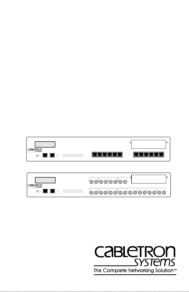
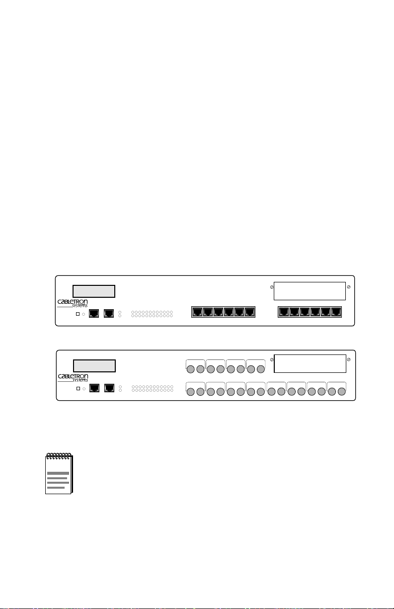
The ESX-1320 and ESX-1380 Ethernet Workgroup Switches, shown in
Figure 1-1, are standalone network switch devices. Except for the
difference in the network Media supported (ESX-1320, RJ45 Twisted Pair
ports and ESX-1380, Multimode Fiber Optic ST ports), the two ESX
switches are identical in operation.
MULTI PORT ETHERNET SWITCH
ESX-1320
DISPLAY RESET
ESX-1380
DISPLAY RESET
WITH FDSE™AND LANVIEW
COM 2 COM 1
MULTI PORT ETHERNET SWITCH
WITH FDSE™AND LANVIEW
COM 2 COM 1
®
PWR
CPU
123456789101112
®
PWR
CPU
123456789101112
RECEIVE
TRANSMIT
PORT
RECEIVE
TRANSMIT
PORT
PORT 9
PORT 1
STY
XMT
LNK
RCV
7X 8X 9X 10X 11X 12X1X 2X 3X 4X 5X 6X
PORT 12
PORT 11
PORT 10
TXRX
TXRX
TXRX
PORT 4
PORT 3
PORT 2
TXRX
TXRX
TXRX
STY
PORT 5
XMT
LNK
RCV
PORT 6
TXRX
TXRX
TXRX
TXRX
PORT 7
BRIM-A100
BRIM-A100
PORT 8
TXRX
TXRX
1574-01
Figure 1-1 ESX-1320 and ESX-1380 Switches
Throughout this manual the term ESX refers to both switches,
NOTE
the ESX-1320 and the ESX-1380. If the information applies to
only one of the switches, then that switch is referred to by its
model name, ESX-1320 or ESX-1380.
ESX-1320/ESX-1380 Local Management Guide 1-1
Page 12

Chapter 1:
Introduction
This manual describes the following:
• Accessing the Local Management application
• Identifying and operating the types of fields used by Local
Management
• Navigating through Local Management fields and menus
• Using Local Management screens to perform management operations
1.1 USING THIS MANUAL
A general working knowledge of basic network operations and an
understanding of management applications is helpful prior to using
Cabletron Systems Local Management.The following summarizes the
organization of this manual.
Chapter 1,
Introduction
, outlines the contents of this manual, provides an
overview of Local Management, and e xplains how to use the management
screens.
Chapter 2,
Local Management Requirements
, describes the setup
requirements for accessing Local Management. It also explains how to
configure a management terminal and connect it to the ESX.
Chapter 3,
Accessing Local Management,
describes how to access the
Main Menu screen and navigate the Local Management screens.
Chapter 4,
The System Level Screen
, describes how to use the System
Level screen, its functions, and operations.
Chapter 5,
The SNMP Community Names Screen
, explains how to
control access to the ESX by assigning community names.
Chapter 6,
The SNMP Traps Screen
, explains how to configure the ESX
to send SNMP trap messages to multiple network management stations.
Chapter 7,
The FLASH Download Screen
, describes how to download a
new firmware image to the ESX FLASH EEPROM.
Chapter 8
The Bridge Setup Screen
, describes how to configure the ESX
for bridge functions.
Chapter 9,
The Device Specific Setup Screen
, describes how to
configure the ESX interface 13 connection method.
1-2 ESX-1320/ESX-1380 Local Management Guide
Page 13

Document Conventions
Chapter 10,
The Port Redirect Function Screen
, discusses how to set
each one of the ESX ports as a source or destination port.
Chapter 11,
The Component Status Screen
, discusses how to view the
status of ESX MIB components.
Chapter 12,
The MIB-2 Statistics Screen
, discusses how to configure the
ESX to gather statistics for each interface.
Chapter 13,
The MIB Navigator Screen
, describes how to access and
use the MIB Navigator screen. This chapter also includes examples for
MIB Navigator commands.
1.2 DOCUMENT CONVENTIONS
The following conventions are used throughout this document:
Note
NOTE
TIP
symbol. Calls the reader’s attention to any item of
information that may be of special importance.
Tip
symbol. Conveys helpful hints concerning procedures or
actions.
!
CAUTION
Caution
damage to the equipment.
symbol. Contains information essential to avoid
1.3 LOCAL MANAGEMENT OVERVIEW
Cabletron Systems Local Management is a management tool that allows a
network manager to perform the following tasks:
• Configure the devices interconnected to form a network
• Monitor the network’s performance
• Control user access to the network and its components for the purpose
of security
ESX-1320/ESX-1380 Local Management Guide 1-3
Page 14

Chapter 1:
Introduction
1.3.1 The Management Agent
The management agent is a process within the ESX which collects
statistical information (e.g., frames received, errors detected) about the
managed network’s operational performance. Local Management
communicates with the management agent for the purpose of viewing
statistics or issuing management commands.
1.3.2 In-Band vs. Out-of-Band
Network management systems are often classified as either in-band or
out-of-band. In-band network management passes data along the same
medium (cables, frequencies) used by all other stations on the network.
An example of an in-band network management system is Cabletron
Systems SPECTRUM.
Out-of-band network management passes data along a medium that is
entirely separate from the network’s common data carrier, for example, a
cable connection between a dumb terminal and the ESX COM port.
Cabletron Systems Local Management is an out-of-band network
management system.
A device connected out-of-band to the management agent is not
connected to the LAN. This type of connection allows you to
communicate with a network device even when that device is unable to
communicate through the network, for example, at the time of
installation.
1.3.3 Local vs. Remote Management
Network management applications are usually described as either local or
remote management applications. Local Management applications reside
within the management device’s management agent. Remote
management applications run within the circuits of another device that
provides management services. This allows you to perform network
management from a remote location.
1-4 ESX-1320/ESX-1380 Local Management Guide
Page 15

Local Management Requirements
1.4 LOCAL MANAGEMENT REQUIREMENTS
The ESX provides two communication ports, labeled COM 1 and COM 2,
that support a management terminal connection. To access Local
Management, connect one of the following systems to either COM 1 or
COM 2:
• Digital Equipment Corporation VT series terminal
• VT type terminal running emulation programs for the Digital
Equipment Corporation VT series
• IBM or compatible PC running a VT series emulation software
package
You can also access Local Management using a Telnet connection
through one of the ESX network ports.
Chapter 2,
Local Management Requirements
, describes the setup
requirements for accessing Local Management. It also explains how to
configure a management terminal and connect it to the ESX.
ESX-1320/ESX-1380 Local Management Guide 1-5
Page 16
Chapter 1:
Introduction
1.5 LOCAL MANAGEMENT SCREEN ELEMENTS
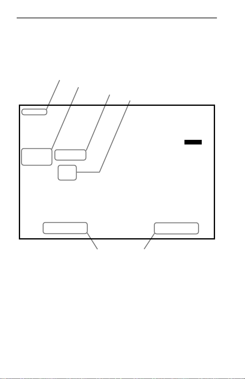
Local Management screens consist of five basic elements, or fields.
Figure 1-2 shows a Local Management screen and points out the various
types of fields.
EVENT MESSAGE FIELD
DISPLAY FIELDS
INPUT FIELDS
SELECTION FIELDS
SAVED OK
ESX-13XX Local Management
System Date:
01/23/96
SYSTEM LEVEL
Flash Image Version XX.XX.XX
System Time:
14:23:00
Host IP Address 000.000.000.000
Subnet Mask 255.255.0.0
Phys Address 00-00-1D-16-26-F8
COM 1 Application:
COM 2 Application:
[NONE]
[LM]
SAVE RETURN
Figure 1-2 Sample Local Management Screen
Default Gateway NONE DEFINED
Default Interface NONE DEFINED
COMMAND FIELDS
090836
1-6 ESX-1320/ESX-1380 Local Management Guide
Page 17

Local Management Screen Elements
The following list explains each of the Local Management fields:
Event Message Field
This field briefly displays messages that indicate if a Local Management
procedure was executed correctly or incorrectly, that changes were saved
or not saved to Non-Volatile Random Access Memory (NVRAM), or that
a user did not have access privileges to an application.
Table 1-1 describes the most common event messages. Event messages
related to specific Local Management applications are described with
those applications throughout this manual.
Table 1-1 Event Messages
Message What it Means
SAVED OK
NOT SAVED?--PRESS SAVE TO
KEEP CHANGES
NOTHING T O SAVE
Display Fields
One or more fields were modified,
and saved to NVRAM.
One or more fields were modified,
but not saved to NVRAM.
The SAVE command was executed,
but nothing was saved to NVRAM.
Display fields cannot be edited. These fields may display information
which never changes, or information which may change as a result of
Local Management operations, user selections, or network monitoring
information.
Input Fields
Input fields require the entry of keyboard characters. IP addresses, System
Date, and System Time are examples of Input fields.
Selection Fields
Selection fields provide a series of possible values. Only applicable v alues
appear in Selection fields.
Command Fields
Command fields are located at the bottom of Local Management screens.
Command fields are used to exit Local Management screens and to save
Local Management entries.
ESX-1320/ESX-1380 Local Management Guide 1-7
Page 18

Chapter 1:
Introduction
1.6 LOCAL MANAGEMENT KEYBOARD
CONVENTIONS
All key names appear in this manual as capital letters. For example, the
Enter key appears as ENTER, the Escape key appears as ESC, and the
Backspace key appears as BACKSPACE. The table below explains the
keyboard conventions used in this manual as well as the key functions.
Key Function
ENTER and RETURN These are selection keys that perform
the same Local Management
function. For example, “Press
ENTER” means that you can press
either ENTER or RETURN, unless
this manual specifically instructs you
otherwise.
ESC This key lets you escape from a Local
Management screen without saving
your changes. For example, “Press
ESC twice” means that you must
quickly press the escape key two
times to exit the Local Management
screen.
SPACE bar and BACKSPACE These keys cycle through selections
in some Local Management fields.
Use the SPACE bar to cycle forward
through selections and use
BACKSPACE to cycle backward
through selections.
Arrows These are navigation keys. Use the
UP-ARROW, DOWN-ARROW,
LEFT-ARROW, and RIGHT-ARROW
keys to move the screen cursor. For
example, “Use the arrow keys”
means to press whichever arrow key
moves the cursor to the desired field
on the Local Management screen.
1-8 ESX-1320/ESX-1380 Local Management Guide
Page 19

Navigating Local Management Screens
[+/=] This key increments values in some
Local Management selection fields.
For example, “Press [
press the plus/equal key.
[–] Key This key decreases values from some
Local Management selection fields.
For example, “Press [–]” means to
press the minus key.
DEL The DEL (Delete) key removes
characters from a Local Management
Selection field. For example, “Press
DEL” means to press the delete key.
+/=
]” means to
1.7 NAVIGATING LOCAL MANAGEMENT SCREENS
To navigate within a Local Management screen, use the arrow ke ys of the
terminal or the workstation providing terminal emulation services. The
Local Management screen cursor responds to the LEFT, RIGHT, UP, and
DOWN arrow keys. Each time you press an arrow key, the Local
Management screen cursor moves to the next available field in the
direction of the arrow key.
The Local Management screen cursor only moves to fields which can be
selected or used for input. This means that the cursor jumps over display
fields and empty lines on the Local Management screen.
The Local Management screen cursor provides wrap-around operation.
This means that a cursor located at the edge of a screen, when moved in
the direction of that edge, “wraps around” to the outermost selectable
item on the opposite side of the screen which is on the same line or
column.
ESX-1320/ESX-1380 Local Management Guide 1-9
Page 20

Chapter 1:
Introduction
1.8 GETTING HELP
If you need additional support related to Local Management, or if you
have any questions, comments, or suggestions concerning this manual,
contact Cabletron Systems Technical Support:
By phone (603) 332-9400
Monday – Friday; 8
By CompuServe GO CTRON from any ! prompt
By Internet mail [email protected]
By FTP ctron.com (134.141.197.25)
Login anonymous
Password your email address
Before calling Cabletron Systems Technical Support, have the following
information ready:
• A description of the failure
• A description of any action(s) already taken to resolve the problem
(e.g., changing mode switches, rebooting the unit, etc.)
• A description of your network environment (layout, cable type, etc.)
A.M. – 8 P.M. Eastern T ime
• Network load and frame size at the time of trouble (if known)
• The serial and revision numbers of all Cabletron Systems products in
the ESX network
• The device history (i.e., have you returned the device before, is this a
recurring problem, etc.)
• Any previous Return Material Authorization (RMA) numbers
1-10 ESX-1320/ESX-1380 Local Management Guide
Page 21

CHAPTER 2
LOCAL MANAGEMENT REQUIREMENTS
This chapter describes how to attach a Local Management terminal to the
Cabletron Systems host device, and lists the setup and configuration
requirements for the following equipment:
• Console/terminal
• Console cable
• Console cable connections
2.1 CONFIGURING A LOCAL MANAGEMENT
TERMINAL
The following instructions explain how to configure your management
terminal (console) to communicate with Local Management. Refer to
your specific management terminal manual for more instructions if
necessary.
To access Local Management, use one of the following systems:
• Digital Equipment Corporation VT series terminal
• VT type terminal running emulation programs for the Digital
Equipment Corporation VT series
• IBM or compatible PC running a VT series emulation software
package
ESX-1320/ESX-1380 Local Management Guide 2-1
Page 22

Chapter 2: Local Management Requirements
2.2 MANAGEMENT T ERMINAL SETUP
REQUIREMENTS
Table 2-1 lists the setup parameters for the management terminal. If the
management terminal is a Digital Equipment Corporation VT220 or a
VT320 terminal, press F3 to access the Setup Directory. If the
management terminal uses terminal emulation of the VT320, refer to the
equipment user manual for setup procedures.
Table 2-1 Terminal Setup Parameters
Menu Function Selection
Display Setup
General Setup
Communications
Setup
Keyboard Setup
Columns 80 Columns
Controls Interpret Controls
Auto Wrap No Auto Wrap
Test Cursor Cursor
Mode 7 Bit Control
Cursor Keys Normal Cursor Keys
Transmit Transmit = 9600
Receive Receive = Transmit
XOFF any option
Bits, Parity 8 Bits, No Parity
Stop Bit 1 Stop Bit
Local Echo No Local Echo
Port
Transmit any option
Auto Answerback No Auto Answerback
Auto Repeat any option
Keyclick any option
Margin Bell Margin Bell
Warning Bell Warning Bell
Auto Answerback No Auto Answerback
DEC-423, Data Leads
Only
2-2 ESX-1320/ESX-1380 Local Management Guide
Page 23

Cable Configuration for the Management Terminal
2.3 CABLE CONFIGURATION FOR THE
MANAGEMENT T ERMINAL
This section outlines the proper cable configurations to connect a
management terminal to the ESX.
You need an adapter kit containing the following items to connect a
terminal to the ESX:
• One RS232 cable
• One VT series adapter
• One device cable
The adapter you use depends on whether you connect a VT220 or a
VT320 terminal or a PC emulating a VT320 to the ESX COM port. Read
the information included with the adapter kit to make sure that you are
using the correct adapter.
To configure the cables, perform the following steps:
1. Plug a straight-through twisted pair cable (e.g., an RS232 cable) into
an ESX COM port.
2. Plug the other end of the RS232 cable into the adapter.
3. Connect the adapter into the device cable and plug the other end of the
device cable into the terminal.
4. Power on the terminal. Access to Local Management is automatic;
however, because of the auto-baud detection, you may need to press
ENTER.
ESX-1320/ESX-1380 Local Management Guide 2-3
Page 24

Chapter 2: Local Management Requirements
2.4 ESTABLISHING A TELNET CONNECTION
Once the ESX has a valid IP address, you can establish a Telnet session
with Local Management from any TCP/IP based node on the network.
Telnet connections to the host device require the community name
passwords assigned at the SNMP Community Names screen. Refer to the
SNMP Community Names section of this manual for additional
information about community names.
NOTE
See the instructions included with the Telnet application for
information about establishing a Telnet session.
2-4 ESX-1320/ESX-1380 Local Management Guide
Page 25

CHAPTER 3
ACCESSING LOCAL MANAGEMENT
This chapter explains how to access and use the Local Management menu
screens. Menu screens provide a path to the setup screens, statistic
screens, and status screens.
3.1 USING THE MENU SCREENS
Verify that your terminal has been properly connected to the ESX before
proceeding.
To access Local Management, perform the following steps:
1. Power on the terminal. The ESX Password screen, Figure 3-1,
appears.
ESX-13XX Local Management
CABLETRON Systems, Incorporated
P.O. Box 5005
Rochester, NH 03867-5005 USA
(603) 332-9400
(c) Copyright CABLETRON Systems, Inc. 19XX
Flash Image Version:
BOOTPROM Version:
Board Revision: X.X
Enter Password:
XX.XX.XX
XX.XX.XX
090820
Figure 3-1 The ESX Password Screen
ESX-1320/ESX-1380 Local Management Guide 3-1
Page 26

Chapter 3: Accessing Local Management
2. Enter your password and press ENTER. The default super-user access
password is “public” or press ENTER.
NOTE
Your password is one of the community names specified in the
SNMP Community Names screen. Access to certain Local
Management capabilities depends on the degree of access
accorded that community name. See the SNMP Community
Names section.
• If you enter an inv alid password the cursor returns to the be ginning of
the password entry field.
• If you enter a valid password, the associated access level displays at
the bottom of the screen and the Main Menu screen, Figure 3-3,
appears.
• If no activity occurs for sev eral minutes the Password screen reappears
indicating that you must re-enter the password.
3.2 NAVIGATING LOCAL MANAGEMENT SCREENS
Local Management consists of a series of menu screens that provide a
path to each of the Local Management function screens. You navigate
through Local Management by selecting items from the menu screens.
ESX Local Management consists of the following menu screens:
• Main Menu screen
• Setup Menu screen
• Status Menu screen
• Statistics Menu screen
• MIB Navigator screen
Figure 3-2 shows the hierarchy of Local Management screens.
3-2 ESX-1320/ESX-1380 Local Management Guide
Page 27

Navigating Local Management Screens
System Level
Setup Menu
Main MenuPassword
Status Menu
SNMPCommunity Names
SNMP Traps
Flash Download
Bridge Setup
Device Specific
Port Remap Setup
Component Status
Statistics Menu
MIB Navigator
Figure 3-2 Hierarchy of Local Management Screens
MIB-2 Statistics
090830
3.2.1 Selecting Local Management Menu Screen Items
To select items on a Local Management menu screen, perform the
following steps:
1. Use the arrow keys to highlight a menu item.
2. Press ENTER. The selected Local Management menu screen appears.
ESX-1320/ESX-1380 Local Management Guide 3-3
Page 28

Chapter 3: Accessing Local Management
3.2.2 Exiting Local Management Screens
To exit any of the Local Management screens, perform the following
steps:
1. Use the arrow keys to highlight the RETURN command field at the
bottom of the Local Management screen.
2. Press ENTER. The previous screen in the Local Management
hierarchy appears.
NOTE
You can also exit Local Management screens by pressing ESC
twice. This exit method does not warn you about unsaved
changes and all unsaved changes will be lost.
3.2.3 Exiting the Local Management Session
To exit from ESX Local Management, perform the following steps:
1. Use the arrow keys to highlight the RETURN command field at the
bottom of the Local Management screen.
2. Press ENTER. The previous screen in the Local Management
hierarchy appears.
3. Repeat steps 1 and 2 until the Main Menu screen appears.
4. Use the arrow keys to highlight the EXIT command field at the bottom
of the Main Menu screen.
5. Press ENTER. The ESX Local Management Password screen appears
and the Local Management session ends.
3-4 ESX-1320/ESX-1380 Local Management Guide
Page 29

The Main Menu Screen
3.3 THE MAIN MENU SCREEN
The Main Menu screen is the starting point from which all the Local
Management screens are accessed. Figure 3-3 shows the Main Menu
screen.
Event Message Line
ESX-13XX Local Management
MAIN MENU
SETUP MENU
STATUS MENU
STATISTICS MENU
MIB NAVIGATOR
Flash Image Version: XX.XX.XX
EXIT
090821
Figure 3-3 The Main Menu
The Main Menu screen displays the following menu items:
• Setup Menu – The Setup Menu provides access to Local Management
screens that are used to configure the ESX.
• Status Menu – The Status Menu provides access to the Component
Status screen which displays the operational and administrative status
of ESX MIB components.
• Statistics Menu – The Statistics Menu provides bridge statistics and
performance information for the switch interfaces of the ESX.
• MIB Navigator – The MIB Navigator is a Local Management utility
which allows the user to access, monitor , and set specific Management
Information Base (MIB) items within the ESX.
ESX-1320/ESX-1380 Local Management Guide 3-5
Page 30

Chapter 3: Accessing Local Management
3.4 THE SETUP MENU SCREEN
The Setup Menu provides access to Local Management screens that are
used to configure or alter the configuration of the ESX. Examples of
functions accessible through the Setup Menu include configuring the host
IP address and subnet mask, assigning SNMP community names, and
configuring SNMP trap notification. Figure 3-4 shows the Setup Menu.
Event Message Line
ESX-13XX Local Management
SETUP MENU
SYSTEM LEVEL
SNMP COMMUNITY NAMES
SNMP TRAPS
FLASH DOWNLOAD
BRIDGE SETUP
DEVICE SPECIFIC SETUP
Flash Image Version XX.XX.XX
PORT REMAP SETUP
RETURN
090822
Figure 3-4 The Setup Menu
The Setup Menu displays the following menu items:
• System Level – The System Level Setup screen allows you to
configure basic operating parameters for the ESX.
• SNMP Community Names – The SNMP Community Names Setup
screen allows you to change or review the community names used as
access passwords for local management operation.
• SNMP Traps – The SNMP Traps Setup screen provides display and
configuration access to the table of IP addresses used for trap
destinations and associated community names.
3-6 ESX-1320/ESX-1380 Local Management Guide
Page 31

The Status Menu Screen
• FLASH Download – The FLASH Download screen allows you to
download a firmware image from a TFTP server.
• Bridge Setup – The Bridge Setup screen allows you to select a
Spanning Tree protocol and enable/disable ports.
• Device Specific Setup – Provides display and conf iguration access to
the specific BRIM in interface 13.
• Port Remap Setup – The Port Remap screen allows you to copy
frames from a source port to a destination port.
3.5 THE STATUS MENU SCREEN
Figure 3-5 shows the Status Menu screen. The Status Menu screen
provides access to the Component Status screen.
Event Message Line
ESX-13XX Local Management
STATUS MENU
Flash Image Version: XX.XX.XX
COMPONENT STATUS
RETURN
090826
Figure 3-5 The Status Menu Screen
ESX-1320/ESX-1380 Local Management Guide 3-7
Page 32

Chapter 3: Accessing Local Management
3.6 THE STATISTICS MENU SCREEN
Figure 3-6 shows the Statistics Menu screen. The Statistics Menu screen
provides access to the MIB-2 Statistics screen.
Event Message Line
ESX-13XX Local Management
STATISTICS MENU
MIB-2 STATISTICS
Flash Image Version: XX.XX.XX
RETURN
090826B
Figure 3-6 The Statistics Menu Screen
3-8 ESX-1320/ESX-1380 Local Management Guide
Page 33

CHAPTER 4
THE SYSTEM LEVEL SCREEN
This chapter explains how to use the System Level screen to set the
following parameters:
System Date System Time
Host IP Address Subnet Mask
Default Interface Default Gateway
COM 1 Port Application COM 2 Port Application
4.1 SYSTEM LEVEL SCREEN FIELDS
Figure 4-1 shows the ESX System Level screen.
Event Message Line
ESX-13XX Local Management
SYSTEM LEVEL
Flash Image Version XX.XX.XX
System Date:
Host IP Address 000.000.000.000
Subnet Mask 255.255.0.0
Phys Address 00-00-1D-16-26-F8
COM 1 Application:
COM 2 Application:
Field Sensitive Help Line
12/30/95
[NONE]
[LM]
SAVE RETURN
Default Gateway NONE DEFINED
Default Interface NONE DEFINED
14:23:00System Time:
090823
Figure 4-1 The System Level Screen
ESX-1320/ESX-1380 Local Management Guide 4-1
Page 34

Chapter 4: The System Level Screen
The following definitions explain each System Level screen field.
System Date
Use this field to enter the system date.
System Time
Use this field to enter the system time.
Host IP Address
Use this field to enter the IP address of the ESX.
Subnet Mask
Use this field to enter the subnet mask for the ESX. Subnets are logical
divisions of the network that isolate groups of devices.
NOTE
Default Gateway
The subnet mask will default to a standard Class A, B, or C
subnet mask depending upon the IP address Class of the entry
in the Host IP Address field. This default subnet mask may be
modified if needed.
Use this field to enter the default gateway for the ESX. The default
gateway is the IP address of the network device (gateway or router) used
to forward SNMP traps to a management station. The default setting for
this field is NONE DEFINED.
Phys Address
This field displays the physical MAC address of the ESX. You can not
modify the physical MAC address.
Default Interface
Use this field to select the default interface for the ESX default gateway.
The default interface is the channel that is set up to handle message traffic
to the default gateway. The default setting for this field is NONE
DEFINED.
COM 1 Application
Use this field to select the communication port’s application. The setting
for this field is LM.
4-2 ESX-1320/ESX-1380 Local Management Guide
Page 35

Setting the System Date
COM 2 Application
Use this field to select the communication port’s application. The setting
for this field is LM.
4.2 SETTING THE SYSTEM DATE
To set the system date, perform the following steps:
1. Use the arrow keys to highlight the System Date field.
2. Enter the date in a MM/DD/YY format.
NOTE
When entering the date in the system date field, you do not
need to add separators between month, day, and year
numbers, as long as each entry uses two decimal numbers.
For example, to set the date to 03/17/96, type “031796” in the
System Date field.
3. Press ENTER to set the system calendar.
4. Use the arrow keys to highlight the SAVE command field at the
bottom of the screen and press ENTER.
If the date entered was a valid format, the Event Message field at the
top of the screen displays “SAVED OK”. If the entry was not valid,
Local Management does not alter the current value and refreshes the
System Date field with the previous value.
ESX-1320/ESX-1380 Local Management Guide 4-3
Page 36

Chapter 4: The System Level Screen
4.3 SETTING THE SYSTEM TIME
To set the system clock, perform the following steps:
1. Use the arrow keys to highlight the System Time field.
2. Enter the time in a 24-hour format, HH:MM:SS.
NOTE
When entering the time in the system time field, you do not
need to add separators between hours, minutes, and seconds ,
as long as each entry uses two decimal numbers. F or e xample ,
to set the time to 6:45
field.
A.M., type “064500” in the System Time
3. Press ENTER to set the system clock.
4. Use the arrow keys to highlight the SAVE command field at the
bottom of the screen and press ENTER.
If the time entered was a valid format, the Event Message field at the
top of the screen displays “SAVED OK”. If the entry was not valid,
Local Management does not alter the current value and refreshes the
System Time field with the previous value.
4-4 ESX-1320/ESX-1380 Local Management Guide
Page 37

Setting the Host IP Address
4.4 SETTING THE HOST IP ADDRESS
To set the host IP address, perform the following steps:
1. Use the arrow keys to highlight the Host IP Address field.
2. Enter the IP address using Decimal Dotted Notation (DDN) format.
For example: 134.141.25.17
3. Press ENTER. If the IP address entered was a valid format, the cursor
returns to the beginning of the Host IP Address field. If the entry was
not valid, the Event Message field displays “INVALID IP ADDRESS
OR FORMAT ENTERED”. Local Management does not alter the
current value and refreshes the Host IP Address field with the previous
value.
4. Use the arrow keys to highlight the SAVE command field.
Changing the ESX IP address requires a reset of the module.
Local Management will automatically reset the ESX, which will
!
CAUTION
go through startup operations before bridging will resume.
5. Press ENTER. The Event Message field at the top of the screen
displays “SAVED OK”. This message flashes briefly, then the Event
Message line will display “System Reboot in Progress....” Local
Management will be terminated and the screen will freeze while the
ESX resets.
NOTE
ESX-1320/ESX-1380 Local Management Guide 4-5
After the ESX resets, the Password screen appears and you
must re-enter Local Management.
Page 38

Chapter 4: The System Level Screen
4.5 SETTING THE SUBNET MASK
Subnets are logical divisions of the network. To change the subnet mask
from its default value, perform the following steps:
1. Use the arrow keys to highlight the Subnet Mask field.
2. Enter the subnet mask using Decimal Dotted Notation (DDN) format.
Values for each decimal must range from 0-255.
For example: 255.255.0.0
3. Press ENTER. If the subnet mask entered was a valid format, the
cursor returns to the beginning of the Subnet Mask field. If the entry
was not valid, the Event Message field displays “INVALID SUBNET
MASK OR FORMAT ENTERED”. Local Management does not alter
the current value and refreshes the Subnet Mask field with the
previous value.
4. Use the arrow keys to highlight the SAVE command field.
5. Press ENTER. The Event Message field at the top of the screen
displays “SAVED OK”.
4.6 SETTING THE DEFAULT GATEWAY
To set the default gateway, perform the following steps:
1. Use the arrow keys to highlight the Default Gateway field.
2. Enter the IP address of the default gateway using DDN format.
For example: 134.141.79.121
3. Press ENTER. If the default gateway entered was a valid format, the
cursor returns to the beginning of the Default Gateway field. If the
entry was not valid, the Event Message field displays “INVALID
DEFAULT GATEWAY OR FORMAT ENTERED”. Local
Management does not alter the current value and refreshes the Default
Gateway field with the previous value.
4. Use the arrow keys to highlight the SAVE command field.
5. Press ENTER. The Event Message field at the top of the screen
displays “SAVED OK”.
4-6 ESX-1320/ESX-1380 Local Management Guide
Page 39

Setting the Default Interface
4.7 SETTING THE DEFAULT INTERFACE
To set the default interface, perform the following steps:
NOTE
Before setting the default interface, you need to assign a
default gateway.
1. Use the arrow keys to highlight the Default Interface field.
2. Enter the interface number for the default gateway in this field.
3. Press ENTER. If the interface entered was a valid format, the cursor
returns to the beginning of the Subnet Mask field. If the entry was not
valid, the Event Message field displays “PERMISSIBLE RANGE:
1...1”. Local Management does not alter the current value and
refreshes the Default Interface field with the previous value.
4. Use the arrow keys to highlight the SAVE command field.
5. Press ENTER. The Event Message field at the top of the screen
displays “SAVED OK”.
4.8 COM PORT APPLICATIONS
The ESX communication ports support the following application:
• Cabletron Systems Local Management connections
ESX-1320/ESX-1380 Local Management Guide 4-7
Page 40

Chapter 4: The System Level Screen
4-8 ESX-1320/ESX-1380 Local Management Guide
Page 41

CHAPTER 5
THE SNMP COMMUNITY NAMES SCREEN
This chapter explains how to assign community names. Community
names allow you to control Local Management access by establishing
three passwords. Each password controls varying levels of access to ESX
Local Management. Figure 5-1 shows the SNMP Community Names
screen.
Event Message Line
ESX-13XX Local Management
SNMP COMMUNITY NAMES
Flash Image Version: XX.XX.XX
Community Name
public
public
public
SAVE RETURN
Access Policy
read-only
read-write
super-user
Figure 5-1 The SNMP Community Names Screen
090824
ESX-1320/ESX-1380 Local Management Guide 5-1
Page 42

Chapter 5: The SNMP Community Names Screen
5.1 COMMUNITY NAME ACCESS POLICY
In order to perform any operations in the SNMP Community Names
screen, you must have used the super-user community name at the User
Password prompt when initiating the Local Management session. The
default community name for each access level is public or press ENTER.
The following definitions explain each of the three levels of access:
read-only
This access level allo ws reading of de vice parameters including read-only
community names.
read-write
This access level allows the reading of parameters and the read-only and
read-write community names. The read-write access level also allows the
editing of some device parameters, not including community names.
super-user
This access level allows full management privileges.
5.2 SETTING SNMP COMMUNITY NAMES
To set a community name, perform the following steps:
1. Use the arrow keys to highlight the community name you want to
change.
2. Type the new community name and press ENTER. The old
community name text disappears and is replaced by the new
community name.
3. Use the arrow keys to highlight the SAVE command field.
4. Press ENTER. The Event Message field at the top of the screen
displays “SAVED OK”.
CAUTION
5-2 ESX-1320/ESX-1380 Local Management Guide
If you edit the super-user community name, be certain you do
not forget it. If you do, you will be unable to perform Local
!
Management functions without returning the community names
to their factory default configurations.
Page 43

CHAPTER 6
THE SNMP TRAPS SCREEN
This chapter explains how to configure the SNMP Traps screen to allow
the ESX to send traps to as many as eight remote management
workstations. SNMP traps are messages about network events and device
operational statistics. The following sections explain SNMP Trap screen
fields and instructions for configuring them. Figure 6-1 shows the SNMP
Traps screen.
Event Message Line
ESX-13XX Local Management
0.0.0.0
0.0.0.0
0.0.0.0
0.0.0.0
0.0.0.0
0.0.0.0
0.0.0.0
0.0.0.0
SNMP TRAPS
Trap Community NameTrap Destination Enable Traps
public
public
public
public
public
public
public
public
Flash Image Version: XX.XX.XX
[NO]
[NO]
[NO]
[NO]
[NO]
[NO]
[NO]
[NO]
SAVE
RETURN
090825
Figure 6-1 The SNMP Traps Screen
6.1 TRAP TABLE SCREEN FIELDS
The following definitions explain each of the SNMP Traps screen fields:
Trap Destination
Use this field to enter the IP address of the management workstation
designated to receive SNMP traps from the ESX.
ESX-1320/ESX-1380 Local Management Guide 6-1
Page 44

Chapter 6: The SNMP Traps Screen
Trap Community Name
This field allows you to enter the community name which provides the
desired level of trap access for the management workstation in question.
Some SNMP traps may not be available to stations which are given
read-only or read-write access to the SNMP MIB.
Enable T raps
Use this field to enable the transmission of SNMP traps to the
management workstation.
6.2 SETTING THE SNMP TRAP DESTINATION
Each management workstation designated to receive SNMP traps from
the ESX must have a valid IP address and community name. To set and
enable SNMP trap destination, perform the following steps:
1. Use the arrow keys to highlight the Trap Destination field you want
to modify.
2. Type the IP address of the management workstation designated to
receive SNMP traps from the ESX. This address must be entered in
DDN format.
For example: 134.141.25.17
3. Press ENTER.
4. Use the arrow keys to highlight the Trap Community Name field (on
the same row as the Trap Destination field).
5. Type the community name of the management workstation.
6. Press ENTER.
7. Use the arrow keys to highlight the Enable Traps field (in the same
row as the Trap Destination and Trap Community Name you have just
configured). The default setting for this field is NO.
8. Press SPACE bar or BACKSPACE to set the field to YES.
9. Use the arrow keys to highlight the SAVE command field.
10. Press ENTER. The Event Message field at the top of the screen
displays “SAVED OK”.
6-2 ESX-1320/ESX-1380 Local Management Guide
Page 45

CHAPTER 7
THE FLASH DOWNLOAD SCREEN
This chapter explains how to use the FLASH Download screen to
download a firmware image from a TFTP server to the ESX. Figure 7-1
shows the FLASH Download screen.
NOTE
Event Message Line
ESX-13XX Local Management
download file and a properly configured download server.
Flash Image Version: XX.XX.XX
FLASH DOWNLOAD
Download Method:
Reboot After Download:
Last Image Server IP:
Last Image File Name:
Download Server IP:
Download File Name:
TFTP Gateway Server IP: 0.0.0.0
EXECUTE RETURN
This section appears only if BOOTPROM is selected as Download Method.
[RUNTIME]
[YES]
0.0.0.0
c:\tftpboot\f2_proxy.hex
0.0.0.0
c:\tftpboot\f2_proxy.hex
FLASH download operations require a properly named
090834
Figure 7-1 The FLASH Download Screen
ESX-1320/ESX-1380 Local Management Guide 7-1
Page 46

Chapter 7: The FLASH Download Screen
7.1 SELECTING A FLASH DOWNLOAD METHOD
1. Use the arrow keys to highlight the Download Method field.
2. Press SPACE bar or BACKSPACE to select a FLASH download
method.
• If you select RUNTIME, the Reboot After Download field
appears.
• If you select BOOTPROM, the Commit to Flash field and the
TFTP Gateway Server IP field appear.
7.1.1 BootPROM Download
If you select a BootPROM download, perform the following steps:
1. Use the arrow keys to highlight the Commit to Flash field.
2. Use the SPACE bar or BACKSPACE to select one of the following:
• YES, if you want the ESX to copy the firmware image to FLASH
memory once the download has been completed.
• NO, if you want the ESX to continue operating without updating
the firmware image currently stored in FLASH memory. If the
ESX is reset or restarted, it will start up from the previous
firmware image which is contained in FLASH memory , discarding
the download firmware in LDRAM.
3. Use the arrow keys to highlight the DDN Format IP Address next to
the TFTP Gateway Server IP field.
4. Enter the IP address of the TFTP gateway server.
7-2 ESX-1320/ESX-1380 Local Management Guide
Page 47

Selecting a FLASH Download Server
7.1.2 Runtime Download
If you select runtime download, perform the following steps:
1. Use the arrow keys to highlight the Reboot After Download field.
2. Use the SPACE bar or BACKSPACE to select one of the following:
• YES, if you want the ESX to reboot and use the new firmware
image immediately.
• NO, if you want the ESX to continue using the existing firmware
image without interrupting network operation. The ESX stores the
new firmware image in FLASH memory . When you reset the ESX,
it boots from FLASH memory using the new image.
7.2 SELECTING A FLASH DOWNLOAD SERVER
Directly below the Download Method and Reboot After Download/
Commit to Flash toggle fields are the Download Server and Download
File display and input fields. The Download Server input field contains
the IP address of the server that the ESX will request a firmware image
from. By default, the Download Server field will display the last IP
address used for a firmware image download. If the same server is to be
used to perform the current download, no changes need to be made to the
Download Server input field.
The Download File input field contains the filename of the firmware
image to be downloaded and the access path used to locate it on the
server. By default, the Download File input field will display the last
firmware image filename and path used to perform a download to the
ESX. If there have been no changes to the server or the filename and path,
these defaults can be used without changes being required.
ESX-1320/ESX-1380 Local Management Guide 7-3
Page 48

Chapter 7: The FLASH Download Screen
7.2.1 Changing the Download Server IP
To change the IP address of the FLASH Download server, perform the
following steps:
1. Use the arrow keys to highlight the DOWNLOAD SERVER IP field.
2. Type the IP address of the server to be used for the download.
3. Press ENTER. The Event Message field at the top of the screen
displays “SAVED OK”.
7.2.2 Changing the Download File Name
To change the name of the firmware image file that Local Management
loads from the FLASH Download server, perform the following steps;
1. User the arrow keys to highlight the DOWNLOAD FILE NAME
field.
2. Type the complete path and filename of the new image file to be
downloaded. You must include all directories and subdirectories
involved in accessing the file. Type the new entry over the previous
entry.
3. Press ENTER. The Event Message field at the top of the screen
displays “SAVED OK”.
7.3 PERFORMING A FLASH DOWNLOAD OPERATION
Perform a FLASH download using either of the following methods:
1. Use the arrow keys to highlight the EXECUTE command field
located at the bottom of the FLASH Download screen.
2. Press ENTER to begin the download. The ESX attempts to download
the file using the IP address, file name, and path provided. This file is
assigned to the FLASH memory of the ESX.
7-4 ESX-1320/ESX-1380 Local Management Guide
Page 49

CHAPTER 8
THE BRIDGE SETUP SCREEN
This chapter explains how to use the Bridge Setup screen to select a
Spanning Tree protocol and enable/disable bridge ports. Figure 8-1 shows
the Bridge Setup screen.
Event Message Line
ESX-13XX Local Management
BRIDGE SETUP
Flash Image Version: XX.XX.XX
SPANNING TREE PROTOCOL:
BRIDGE PORT ADMIN STATUS:
BRIDGE PORT PAIR ADMIN STATUS:
SAVE
Figure 8-1 The Bridge Setup Screen
[IEEE 802.1]
PORT XX --> ALL PORTS
PORT XX --> PORT [YY]
[BRIDGE_PORT XX] RETURN
[ENABLED]
[ENABLED]
090835
ESX-1320/ESX-1380 Local Management Guide 8-1
Page 50

Chapter 8: The Bridge Setup Screen
8.1 BRIDGE SETUP SCREEN FIELDS
The following list describes each of the Bridge Setup screen fields:
Spanning T ree Protocol
Use this field to select a spanning tree protocol. Possible selections for
this field are IEEE 802.1, DEC, or NONE.
Bridge Port Admin Status
Use this field to enable or disable individual ESX bridge ports. Possible
selections for this field are ENABLED or DISABLED.
Bridge Port Pair Admin Status
Use this field to enable or disable bridging between bridge port pairs. For
example, you can enable Port 1 to bridge traffic to all ports except Port 2.
Bridge_Port
X
Use this command field to select the ESX bridge port you want to
configure.
8.2 SELECTING A SPANNING TREE PROTOCOL
T o select the Spanning T ree protocol to be used by the bridge, perform the
following steps:
1. Use the arrow keys to highlight the SPANNING TREE
PROTOCOL field.
2. Press SPACE bar or BACKSPACE to select [IEEE 802.1], [DEC], or
[NONE].
3. Use the arrow keys to highlight the SAVE command field.
4. Press ENTER. The Event Message field at the top of the screen
displays “SAVED OK”.
8-2 ESX-1320/ESX-1380 Local Management Guide
Page 51

Selecting the Port Administrative Status
8.3 SELECTING THE PORT ADMINISTRATIVE STATUS
To select the bridge port administrative status, perform the following
steps:
1. Use the arrow keys to highlight the [BRIDGE_PORT X] field.
2. Press SPACE bar or BACKSPACE to select the bridge port you want
to configure. The selected bridge port appears in the Bridge Port
Admin Status field.
3. Use the arrow keys to highlight the BRIDGE PORT ADMIN
STATUS: PORT X - - > ALL PORTS [ENABLED] field.
4. Press SPACE bar or BACKSPACE to select ENABLED or
DISABLED.
For example, the following bridge setup indicates that bridge port 01
is configured to bridge traffic to all ports:
BRIDGE PORT ADMIN STATUS: PORT 01 - - > ALL PORTS
[ENABLED]
5. Use the arrow keys to highlight the SAVE command field.
6. Press ENTER. The Event Message field at the top of the screen
displays “SAVED OK”.
ESX-1320/ESX-1380 Local Management Guide 8-3
Page 52

Chapter 8: The Bridge Setup Screen
8.4 SELECTING BRIDGE PORT PAIR
ADMINISTRATIVE STATUS
To select the bridge port pair administrative status, perform the follo wing
steps:
1. Use the arrow keys to highlight the [BRIDGE_PORT X] field.
2. Press SPACE bar or BACKSPACE to select the bridge port you want
to configure. The selected bridge port appears in the Bridge Port Pair
Admin Status field.
3. Use the arrow keys to highlight the BRIDGE PORT PAIR ADMIN
STATUS: PORT X - -> PORT [Y] field.
4. Press SPACE bar or BACKSPACE to select the port you want to
enable or disable bridge traffic.
5. Use the arrow keys to highlight the BRIDGE PORT PAIR ADMIN
STATUS: PORT X - -> PORT [Y] [ENABLED] field.
6. Press SPACE bar or BACKSPACE to select ENABLED or
DISABLED.
For example, the following bridge setup indicates that bridge port 01
is configured NOT to bridge traffic to bridge port 02:
BRIDGE PORT PAIR ADMIN STATUS: PORT 01 - - > PORT [02]
[DISABLED]
7. Use the arrow keys to highlight the SAVE command field.
8. Press ENTER. The Event Message field at the top of the screen
displays “SAVED OK”.
8-4 ESX-1320/ESX-1380 Local Management Guide
Page 53

CHAPTER 9
THE DEVICE SPECIFIC SETUP SCREEN
This chapter identifies the Device Specific Setup screen. For display and
configuration access, refer to the manual for the device associated with
this interface. Figure 9-1 shows the Device Specific Setup screen.
Event Message Line
ESX-13XX Local Management
MODULE SPECIFIC SETUP
Flash Image Version XX.XX.XX
SAVE
Field Sensitive Help Line
RETURN
090840
Figure 9-1 The Device Specific Setup Screen
ESX-1320/ESX-1380 Local Management Guide 9-1
Page 54

Chapter 9: The Device Specific Setup Screen
9-2 ESX-1320/ESX-1380 Local Management Guide
Page 55

CHAPTER 10
THE PORT REDIRECT FUNCTION SCREEN
Figure 10-1 shows the Port Redirect Function screen. The Port Redirect
Function screen allows you to redirect frames from a source port to a
destination port. You can set a source port to ha v e one or more destination
ports. For example, you can set port 1 as a source port with three
destinations, ports 2, 3, and 4. Traffic from port 1 is then automatically
redirected to ports 2, 3, and 4.
NOTE
frames) is sent to the destination port, normal switching is still
performed for all frames on the source port.
Event Message Line
Although all traffic from the source port (not including errored
ESX-13XX Local Management
Port Redirect Function
Source Port
— —
— —
— —
——
——
——
— —
——
— —
Source Port [ ] Destination Port [ ] Status [ ]
SAVE RETURN
Destination Port
Figure 10-1 The Port Redirect Function Screen
Flash Image Version: XX.XX.XX
— —
— —
— —
——
——
——
— —
——
— —
090837
ESX-1320/ESX-1380 Local Management Guide 10-1
Page 56

Chapter 10: The Port Redirect Function Screen
10.1 PORT REDIRECT FUNCTION SCREEN FIELDS
The following list describes each of the Port Redirect Function screen
fields:
Source Port (Read-only)
Shows which ports are currently set as source ports.
Destination Port (Read-only)
Shows which ports are currently set as destination ports.
Source Port [n] (Selectable)
Allows you to select a port [n] to be changed to a source port.
Destination Port [n] (Selectable)
Allows you to select a port [n] to be changed to a destination port.
Status Port (Selectable)
Allows you to add or delete a source port and/or a destination port.
10.2 CHANGING SOURCE AND DESTINATION PORTS
Add or delete source port and destination port entries, as follows:
1. Use the arrow keys to highlight the SOURCE PORT command field.
2. Press the SPACE bar or BACKSPACE one or more times to increment
or decrement the port number displayed in the brackets [n] until the
appropriate port number is displayed.
3. Use the arrow keys to highlight the DESTINATION PORT
command field.
4. Use the SPACE bar or BACKSPACE again to step to the appropriate
port number for the destination port.
5. Use the arrow keys to highlight the STATUS command field.
6. Use the SPACE bar to select either the ADD or DEL (delete) option.
Press ENTER. This adds or deletes the port selections made in steps 2
and 4 and also updates the screen SOURCE PORT and
DESTINATION PORT list.
10-2 ESX-1320/ESX-1380 Local Management Guide
Page 57

Changing Source and Destination Ports
NOTE
If you want to set more than one port redirect, repeat steps 1
through 6 for each additional setting, then go to step 7 to save
all the new settings at once.
7. Use the arrow keys to highlight the SAVE command field at the
bottom of the screen. Press ENTER. The message “SAVED OK” is
displayed. This saves the new settings and the SOURCE PORT and
DESTINATION PORT read-only fields are updated to include the
new settings.
ESX-1320/ESX-1380 Local Management Guide 10-3
Page 58

Chapter 10: The Port Redirect Function Screen
10-4 ESX-1320/ESX-1380 Local Management Guide
Page 59

CHAPTER 11
THE COMPONENT STATUS SCREEN
Figure 11-1 shows the Component Status screen. The Component Status
screen monitors the status of the MIB Components of the ESX.
Event Message Line
ESX-13XX Local Management
COMPONENT STATUS
Component Name Admin. Status
Flash Image Version: XX.XX.XX
ESX-13XX Chassis MGR
ESX-13XX LIM
ESX-13XX Host Services
ESX-13XX IP Services
ESX-13XX Distributed LAN Monitor
ESX-13XX MIB Navigator
ESX-13XX RMON Default
ESX-13XX RMON Host
ESX-13XX Transparent Bridge
enabled
enabled
enabled
enabled
enabled
enabled
disabled
disabled
enabled
RETURN
090831
Figure 11-1 The Component Status Screen
The Component Status table lists the administrative status (Admin.
Status) of the ESX MIB Components. The Admin. Status field displays
two states: enabled and disabled. Refer to Figure 11-1 for a list of the
ESX MIB Component Names.
ESX-1320/ESX-1380 Local Management Guide 11-1
Page 60

Chapter 11: The Component Status Screen
11-2 ESX-1320/ESX-1380 Local Management Guide
Page 61

CHAPTER 12
THE MIB-2 STATISTICS SCREEN
Figure 12-1 shows the Interface Statistics screen. The Interface Statistics
screen displays error, collision, and traffic statistics for specified ESX
interfaces.
INTERFACE STATISTICS
IN OCTETS:
IN UNICAST PKTS:
IN NONUCAST PKTS:
IN DISCARDS:
IN ERRORS:
OUT OCTETS:
OUT UNICAST PKTS:
OUT NONUCAST PKTS:
OUT DISCARDS:
OUT ERRORS:
CLEAR COUNTERS
INTERFACE: 1 INTERFACE: 2 INTERFACE: 3
0
0
0
0
0
0
0
0
0
0
0
0
0
0
0
0
0
0
0
0
RETURNINTFACE 1 INTFACE 2 INTFACE 3UPDATE-FREQ 3 Sec
0
0
0
0
0
0
0
0
0
0
090832
Figure 12-1 The Interface Statistics Screen
12.1 MIB-2 STATISTICS SCREEN FIELDS
The following list describes the Interface Statistics screen fields:
In Octets
This field displays the number of octets (bytes) received by the interface.
In Unicast Pkts
This field displays the number of unicast packets (packets destined for
one specific address) received on the interface.
ESX-1320/ESX-1380 Local Management Guide 12-1
Page 62

Chapter 12: The MIB-2 Statistics Screen
In Nonucast
This field displays the number of non-unicast packets (multicast and
broadcast packets; packets destined for more than one address) received
by the interface.
In Discards
This field displays the total number of packets discarded by the interface
due to a lack of available resources.
NOTE
In Errors
For interface 13, the BRIM port, the In Discards field displays
the number of times the ESX had to discard packets - any
number of packets - received on interface 13.
This field displays the total number of errors received on the interface.
The number displayed in the In Errors display field can be composed of
the following errors:
• Out Of W indow (OO W) collisions – Collisions caused by a station
on the network violating Carrier Sense and transmitting at will, a
cable failure occurring during the transmission of a frame, or
network propagation delay greater than 51.2 µs.
• Cyclic Redundancy Check (CRC) errors – Errors in the 4-byte
CRC field of a frame which ensures that the data received by the
ESX is the same as the data transmitted by the originating device.
• Alignment Errors – Alignment errors are frames which are
misaligned. A misaligned frame is one which contains a
non-integral number of bytes.
• Runt Packets – Runt packets are packets smaller than the
minimum Ethernet frame size of 64 bytes, not including preamble.
• Giant Packets – Giant packets are those whose size exceeds the
maximum Ethernet frame size of 1,518 bytes, not including
preamble.
NOTE
12-2 ESX-1320/ESX-1380 Local Management Guide
A complete breakdown of In Errors may be obtained from the
ESX RMON MIB. Refer to your remote management package
documentation for instructions on how to obtain this
breakdown.
Page 63

Selecting an Update-Freq
Out Octets
This field displays the number of octets (bytes) transmitted by the
interface.
Out Unicast Pkts
This field displays the number of unicast packets (packets destined for
one specific address) transmitted by the interface.
Out Nonucast
This field displays the number of non-unicast packets (multicast and
broadcast packets; packets destined for more than one address)
transmitted by the interface.
Out Discards
This field displays the total number of packets discarded by the interface
due to a lack of available resources.
Out Errors
This field displays the total number of errors for a given interface:
Update-Freq
Use this field to select the time interval between Network/Slot/Port
counter updates. You can select update intervals in increments of 3
seconds, with the maximum interval being 99 seconds.
Interface
This command field allows you to select the interface(s) you want to
monitor.
12.2 SELECTING AN UPDATE-FREQ
The ESX updates the Bridge Statistics screen every three seconds by
default. The UPDATE-FREQ command allows you to adjust the
frequency in intervals of 3 seconds. The maximum update frequenc y is 99
seconds.
To adjust the UPDATE-FREQ, perform the following steps:
1. Use the arrow keys to highlight the UPDATE-FREQ command field.
ESX-1320/ESX-1380 Local Management Guide 12-3
Page 64

Chapter 12: The MIB-2 Statistics Screen
2. Press [+/=] or [–] until the desired time/frequency appears (this
number increments/decrements in 3 second intervals with a minimum
of 3 seconds and a maximum of 99 seconds).
3. Press ENTER.
12.3 CLEARING STATISTICS COUNTERS
The ESX provides a mechanism for resetting the statistics counter
displays for all interfaces to zero. To clear counters, perform the following
steps:
Local Management does not ask for verification bef ore clearing
counters. Initiating this command will clear the counters
!
CAUTION
1. Use the arrow keys to highlight the CLEAR COUNTERS command
2. Press ENTER. All counters will be reset to zero and be updated after
immediately.
field.
the current UPDATE-FREQ has passed.
12.4 SELECTING AN INTERFACE
When the Bridge Statistics Screen first appears, statistics are displayed for
Interface 1, Interface 2, and Interface 3. To view statistics for other
interfaces, perform the following steps:
1. Use the arrow keys to highlight any one of the INTERFACE fields at
the bottom of the screen.
2. Press SHIFT and [+/=] or [–] until the desired interface appears.
3. Press ENTER. Statistics associated with the selected interface appear.
12-4 ESX-1320/ESX-1380 Local Management Guide
Page 65

CHAPTER 13
THE MIB NAVIGATOR SCREEN
This chapter explains how to use the MIB Navigator utility. The MIB
Navigator allows access to a command set from which you can configure
and manage the ESX. Figure 13-1 shows the MIB Navigator screen.
Event Message Line
Welcome to Cabletron ESX-13XX Revision XX.XX.XX
MIBNav-> help
Commands Available to the User:
arp
ctron
done
help
netstat
pwd
show
snmpset
traceroute
SPECIAL:
done, quit, or exit - Exit from the MIB Navigator.
mib2 - Change MIB directory to MIB II (1.3.6.1.2.1).
ctron - Change MIB directory to cabletron (1.3.6.1.4.1.52).
branch
defroute
exit
ls
next
quit
snmpbranch
snmptree
tree
cd
dir
get
mib2
ping
set
snmpget
su
whoami
For help with a specific command, type 'help <command>'.
MIBNav->
090829
Figure 13-1 The MIB Navigator Screen
ESX-1320/ESX-1380 Local Management Guide 13-1
Page 66
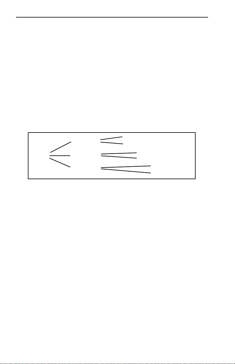
Chapter 13: The MIB Navigator Screen
13.1 MANAGING DEVICE MIBs
The MIB Navigator lets you to manage objects in the ESX Management
Information Bases (MIBs). MIBs are databases of objects used for
managing the device and determining the ESX configuration. The
commands within the MIB Navigator allow you to view and modify a
device’s objects.
The MIB Navigator views the MIB tree hierarchy as a directory.
Figure 13-2 shows the MIB tree hierarchy. Each layer is numerically
encoded, so that every branch group and leaf object in the MIB is
identified by a corresponding number, known as an Object Identifier
(OID). This allows the MIB Navigator to navigate through the MIB and
access the manageable leaf objects.
Object 1.1.1
Object 1.1.2
Object 1.2.1
Object 1.2.2
Object 1.3.1
Object 1.3.2
1574-27
Root 1
Group 1.1
Group 1.2
Group 1.3
Figure 13-2 Hierarchical MIB Tree Structure
Often an ASCII name is assigned to a leaf object’s OID, making it more
readable. To identify the value for the object “ip Forwarding” you would
use the OID (/1/3/6/1/2/1/4/1), or its ASCII name (/iso/org/dod/internet/
mgmt/mib-2/ip/ipForwarding).
13-2 ESX-1320/ESX-1380 Local Management Guide
Page 67

MIB Navigator Command Set Overview
13.2 MIB NAVIGATOR COMMAND SET OVERVIEW
The MIB Navigator command set provides the following commands:
Navigation Commands
Navigation commands allow you to access and manage the MIB for the
device running the MIB Navigator. Some of these commands also provide
user community-string information. The commands are as follows:
– branch – cd – ctron – dir
– get – help – ls – mib2
– next – pwd – set – show
– su – tree – whoami
Built-In Commands
Built-In commands allow you to access and manage network devices
connected to the device running the MIB Navigator . The commands are as
follows:
– arp – defroute – netstat – ping
– snmpbranch – snmpget – snmpset – snmptree
– traceroute
Special Commands
Special Commands allow you to exit from the MIB Navigator. The
commands are as follows:
– done – quit – exit
ESX-1320/ESX-1380 Local Management Guide 13-3
Page 68

Chapter 13: The MIB Navigator Screen
13.2.1 Conventions for MIB Navigator Commands
This manual uses the following conventions for denoting commands:
• Information keyed by the user is shown in this helvetica font.
• Command arguments are indicated by two types of brackets:
- required arguments are enclosed by [ ].
- optional arguments are enclosed by < >.
MIB Navigator command conventions are as follows:
• To abort the output or interrupt a process, the escape character is ^C
(where ^ equals the Control key).
• A slash (/) proceeding an OID issues that command from the root
directory regardless of where you are in the MIB. If no slash precedes
the OID the command issues from your current MIB location.
• Dot notation (1.1.1.1) is equivalent to slash notation (1/1/1/1). Use
slash notation with the navigational commands, and the dot notation
with the built-in commands that are using SNMP to access and manage
network devices.
MIB Navigation Commands are listed in the format shown below:
command:
Syntax: This entry provides the format that the MIB
Navigator command requires. It indicates
where arguments, if any, must be specified.
Description: This entry briefly describes the command and
its uses.
Options: This entry lists any additional fields which may
be added to the command and their format.
Example: This entry shows an example of the command.
13-4 ESX-1320/ESX-1380 Local Management Guide
Page 69

MIB Navigator Command Set Overview
13.2.2 Navigation Commands
The following MIB Navigation commands allow you to move from MIB
object to MIB object within the MIB tree.
branch:
Syntax: branch [path]
Description: The branch command displays all of the leaves
in the MIB tree below a specified path. The
information displayed includes the path name,
the object ASCII name, the type of object (i.e.,
integer, counter , time tick, etc.), and the current
value of each leaf object.
Options: Not Applicable
Example:
MIBNav-> branch
# /1/3/6/1/2/1/7/1
# /1/3/6/1/2/1/7/2
# /1/3/6/1/2/1/7/3
udpInDatagrams
udpNoPorts
udpInErrors
COUNTER
COUNTER
COUNTER
38216
0
0
051456
cd:
Syntax: cd [path] or cd [option]
Description: The cd command allows you to change
directories within a MIB subtree (branch). The
path specified must be valid, or the MIB
Navigator will not perform the cd operation.
Options: .. Moves you one subtree abov e the current one.
/ Moves you to the root.
Example:
MIBNav-> cd iso/org/dod/internet/mgmt
051457
ESX-1320/ESX-1380 Local Management Guide 13-5
Page 70

Chapter 13: The MIB Navigator Screen
ctron:
Syntax: ctron
Description: The ctron command allows you to change
directories to the Cabletron MIB
(1.3.6.1.4.1.52) without keying in the entire
path.
Options: Not Applicable
Example:
MIBNav-> ctron
051458
help:
Syntax: help <COMMAND>
Description: The help command provides general help on
how to use the MIB Navigator or how to use a
particular MIB Navigator command.
Options: Not Applicable
Example:
MIBNav-> help su
Command:
Format:
Allows user to change his/her community name, in
order to allow different access to the MIB.
13-6 ESX-1320/ESX-1380 Local Management Guide
su
su <Community Name>
051459
Page 71

MIB Navigator Command Set Overview
mib2:
Syntax: mib2
Description: The mib2 command allows you to move
directly to the MIB II subtree (1.3.6.1.2.1)
without entering the entire path.
Options: Not Applicable
Example:
MIBNav-> mib2
051460
next:
Syntax: next [path]
Description: The next command enables you to determine
the next leaf in the specified path within the
managed device’s MIB.
Options: Not Applicable
Example:
MIBNav-> next /1/3/6/1/2/1
#/1/3/6/1/2/1/1/1 sysDescr String CtronRev.X.XX.XX
051461
ESX-1320/ESX-1380 Local Management Guide 13-7
Page 72

Chapter 13: The MIB Navigator Screen
pwd:
Syntax: pwd
Description: The pwd command displays the full path name
for the directory in which you are currently
working. The directory is displayed in ASCII
format.
Options: Not Applicable
Example:
MIBNav-> pwd
# /iso/org/dod/internet/mgmt/mib-2
051462
13-8 ESX-1320/ESX-1380 Local Management Guide
Page 73

MIB Navigator Command Set Overview
set:
Syntax: set <OID> <value>
Description: The set command enables you to set the value
of a managed object. This command is valid
only for leaf entries in the current MIB tree, or
for managed objects in the MIB.
If the leaf specified does not exist for the given
path, MIB Navigator asks for a value. The
following lists possible value types:
(i)nteger - number
(c)ounter - number
(g)auge - number
(t)ime ticks - number
o(p)aque - “value” (with quotation marks)
(s)tring - “value” (with quotation marks)
(o)id - OID number with dotted punctuation
(a)ddress - IP address in DDN format
(m)ac - MAC address in hexadecimal format
(n)ull - no type
Options: Not Applicable
Example:
MIBNav-> set /1/3/6/1/4/1/52/1/6/4/7 122.1.1.1
Type: (i)nteger (a)ddress (c)ounter (g)auge (o)id:
051463
ESX-1320/ESX-1380 Local Management Guide 13-9
Page 74

Chapter 13: The MIB Navigator Screen
su:
Syntax: su [community name]
Description: The su command enables you to change your
community name to allow for different access
to the MIB. The community name that you
enter allows you either read only , read-write, or
super-user access to that device’s MIBs,
depending on the level of security access
assigned the password through the SNMP
Community Names screen. See Chapter 5 for
more information about community names.
Options: Not Applicable
Example:
MIBNav-> su public
051464
tree:
Syntax: tree
Description: The tree command provides a display of the
entire MIB for the device. Leaves and
associated values are displayed in columns.
Options: Not Applicable
Example:
MIBNav-> tree
# /1/3/6/1/2/1/1/1
# /1/3/6/1/2/1/1/2
# /1/3/6/1/2/1/1/3
# /1/3/6/1/2/1/1/4
sysDescr
sysObjectId
sysUpTime
sysContact
STRING
OBJECT ID
TIME TICKS
STRING
13-10 ESX-1320/ESX-1380 Local Management Guide
EMRev X.X.X.X
1.3.6.1.4.1.52
8098654
AlZwie/MIS
051465
Page 75

MIB Navigator Command Set Overview
whoami:
Syntax: whoami
Description: The whoami command displays your
community string and access privileges to the
MIB. When using the whoami command one of
these three access levels appears: read-only,
read-write, and super-user.
Options: Not Applicable
Example:
MIBNav-> whoami
# Community Name
# Access Level
: super
: SuperUser
051466
ESX-1320/ESX-1380 Local Management Guide 13-11
Page 76

Chapter 13: The MIB Navigator Screen
13.2.3 Built-In Commands
The built-in commands listed in this section activate functions on the LM
managed device or devices being accessed through MIB Navigation.
arp:
Syntax: arp <options>
Description: The arp command provides access to the ARP
(Address Resolution Protocol) cache, enabling
you to view cache data, delete entries, or add a
static route. Super-user access is required to
delete an entry or add a static route.
Each ARP cache entry lists the network
interface that the device is connected to, the
device’s network address or IP address, the
device’s physical addr ess or MA C address, and
the media type of connection to the device.
Media types are displayed as numbers, which
stand for the following states:
1 - Other
2 - Inv alid entry (cannot ping device, timed out,
etc.)
3 - Dynamic route entry
4 - Static route entry (not subject to change)
Options: -a View cache data
-d delete an IP address entry. Requires
additional arguments: <Interface Number> <IP
address>
-s Adds a static entry. Requires additional
arguments: <Interface Number> <IP address>
<MAC address>
Example:
MIBNav-> arp -d 1 122.144.52.68
# /1/3/6/1/2/1/7/1
# /1/3/6/1/2/1/7/2
# /1/3/6/1/2/1/7/3
13-12 ESX-1320/ESX-1380 Local Management Guide
udpInDatagrams
udpNoPorts
udpInErrors
COUNTER
COUNTER
COUNTER
38216
0
0
Page 77

MIB Navigator Command Set Overview
defroute:
Syntax: defroute [interface number] [IP address]
Description: The defroute command allows you to set the
default IP route to a managed device through
the specified interface.
Options: Not Applicable
Example:
MIBNav-> defroute 2 147.152.42.32
051469
netstat:
Syntax: netstat [option]
Description: The netstat command provides a display of
general network statistics for the managed
device. The netstat command must be used with
one of the two display options.
Options: -i Displays status and capability information for
each interface.
-r Displays routing information for each
interface.
Example:
MIBNav-> netstat -i
Interface + Description
# 1 (ethernet - csmacd)
# 2 (ethernet - csmacd)
# 3 (ethernet - csmacd)
# 4 (ethernet - csmacd)
MIBNav-> netstat -r
Destination
# Default Route
# 134.141.0.0
# 134.141.0.0
MTU
1514
1514
1514
1514
Next-hop
DirectConnection
DirectConnection
DirectConnection
ESX-1320/ESX-1380 Local Management Guide 13-13
Speed
10000000
10000000
10000000
10000000
Admin
up
up
up
up
Oper
up
up
up
up
Interface
1
2
3
MAC Addr
0x00 0x00 0x1d 0x07 0x50 0x0e
0x00 0x00 0x1d 0x07 0x50 0x0f
0x00 0x00 0x1d 0x07 0x50 0x10
0x00 0x00 0x1d 0x07 0x50 0x11
051470
Page 78

Chapter 13: The MIB Navigator Screen
ping:
Syntax: ping [IP address]
Description: The ping command generates an outbound ping
request to check the status (alive/not ali ve) of a
device at a specified IP address.
Options: Not Applicable
Example:
MIBNav-> ping 122.144.40.10
122.144.40.10 is alive
051471
snmpbranch:
Syntax: snmpbranch [IP address] [community name]
[OID]
Description: The snmpbranch command enables you to
query another SNMP device. The command
provides a display of objects that match the
specified OID. If no match is made, no object is
displayed.
Options: Not Applicable
Example:
MIBNav-> snmpbranch 2.4.8.1 public 1.3.6.2.1.1
# /1/3/6/1/2/1/1/1
# /1/3/6/1/2/1/1/2
# /1/3/6/1/2/1/1/3
# /1/3/6/1/2/1/1/4
sysDescr
sysObjectId
sysUpTime
sysContact
STRING
OBJECT ID
TIME TICKS
STRING
13-14 ESX-1320/ESX-1380 Local Management Guide
EMRev X.X.X.X
1.3.6.1.4.1.52
8098654
AlZwie/MIS
051473
Page 79

MIB Navigator Command Set Overview
snmpget:
Syntax: snmpget [IP address] [community name] [OID]
Description: The snmpget command enables you to query
another SNMP device to obtain a value for a
specified object. This command requires the
appropriate community string and object id.
Options: Not Applicable
Example:
MIBNav-> snmpget 22.44.61.22 public 1.3.6.1.2.1.1.1.0
# Cabletron ESX-13XX Revision X.XX.XX
051474
ESX-1320/ESX-1380 Local Management Guide 13-15
Page 80

Chapter 13: The MIB Navigator Screen
snmpset:
Syntax: snmpset [IP address] [community name]
Description: The snmpset command enables you to set the
value of an object in other SNMP devices. This
command requires the appropriate community
string and OID.
When defining a new leaf set, MIB Navigator
asks for a value. The following lists possible
value types:
(i)nteger - number
(c)ounter - number
(g)auge - number
(t)ime ticks - number
o(p)aque - “value” (with quotation marks)
(s)tring - “value” (with quotation marks)
(o)id - OID number with dotted punctuation
(a)ddress - IP address in DDN format
(m)ac - MAC address in hexadecimal format
(n)ull - no type
Options: Not Applicable
Example:
MIBNav-> snmpset 122.44.1.2 public
1.3.6.1.2.1.1.4.0 "Cyrus/MIS"
051475
13-16 ESX-1320/ESX-1380 Local Management Guide
Page 81

MIB Navigator Command Set Overview
snmptree:
Syntax: snmptree [IP address] [community name]
Description: The snmptree command provides a display of
all objects in the device and their corresponding
values.
Options: Not Applicable
Example:
MIBNav-> snmptree 122.144.89.10 public
# /1/3/6/1/2/1/1/1
# /1/3/6/1/2/1/1/2
# /1/3/6/1/2/1/1/3
# /1/3/6/1/2/1/1/4
sysDescr
sysObjectId
sysUpTime
sysContact
STRING
OBJECT ID
TIME TICKS
STRING
EMRev X.X.X.X
1.3.6.1.4.1.52
8098654
AlZwie/MIS
traceroute:
Syntax: traceroute [IP address]
Description: The traceroute command generates a
TRACEROUTE request to a specified IP
address and provides a display of all next-hop
routers in the path to the device. If the device is
not reached, the command displays all next-hop
routers to the point of failure.
Options: Not Applicable
Example:
MIBNav-> traceroute 122.144.11.52
# next-hop[1] 122.144.61.45
# next-hop[2] 122.144.8.113
051476
051477
ESX-1320/ESX-1380 Local Management Guide 13-17
Page 82

Chapter 13: The MIB Navigator Screen
13.2.4 Special Commands
done, quit, exit:
Syntax: done
Description: These commands enable you to exit from the
MIB Navigator and return to the Main Menu
screen.
Options: Not Applicable
Example:
MIBNav-> done
Connection closed
051472
13-18 ESX-1320/ESX-1380 Local Management Guide
Page 83

INDEX
A
Alignment errors 12-2
arp 13-12
B
branch 13-5
Bridge Setup
port administrative status 8-3
spanning tree protocol 8-2
C
Caution 1-3
cd 13-5
COM port application 4-2, 4-3
Command field 1-7
Community names 5-1
read-only 5-2
read-write 5-2
setting 5-2
super-user 5-2
Component Status screen 11-1
Conventions 1-3
CRC errors 12-2
ctron 13-6
D
Default gateway 4-2, 4-6
Default interface 4-2, 4-7
defroute 13-13
Device Specific screen 9-1
Display field 1-7
done 13-18
F
Fields
command 1-7
display 1-7
event message 1-7
input 1-7
selection 1-7
types 1-7
Flash download
bootPROM 7-2
runtime 7-3
screen 7-1
server 7-3
G
Giants 12-2
H
Help (getting) 1-10
help (MIB Navigator
command) 13-6
Hierarchy of screens 3-2
Host IP address 4-2, 4-5
I
Input field 1-7
K
Keyboard conventions 1-8
E
Event Message field 1-7
exit 13-18
ESX-1320/ESX-1380 Local Management Guide Index-1
Page 84

Index
L
Local Management
access levels 5-2
exiting screens 3-4
navigating menu screens 3-2
overview 1-3
requirements 1-5
screen elements 1-6
selecting menu screen items 3-3
M
Management agent 1-4
Management terminal
cable configuration 2-3
setup requirements 2-2
Menu screens
main menu 3-5
setup menu 3-6
statistics menu 3-8
status menu 3-7
MIB
components 11-1
description 13-2
tree hierarchy 13-2
MIB Navigator
built-in commands 13-3
commands 13-4 to 13-18
navigation commands 13-3
special commands 13-3
mib2 13-7
MIB-2 Statistics
clearing counters 12-4
discards 12-2, 12-3
errors 12-2, 12-3
interface 12-3, 12-4
nonucast 12-2, 12-3
octets 12-1, 12-3
screen 12-1
screen fields 12-1
unicast 12-1, 12-3
update-freq 12-3
Moving the cursor 1-9
N
netstat 13-13
Network Management
in-band 1-4
local 1-4
out-of-band 1-4
remote 1-4
next 13-7
Note 1-3
O
OOW collision 12-2
P
Passwords 5-1
Phys address 4-2
ping 13-14
Port Redirect Function screen 10-1
pwd 13-8
Q
quit 13-18
Quitting 3-4
R
Runts 12-2
S
Screen fields
command fields 1-7
Index-2 ESX-1320/ESX-1380 Local Management Guide
Page 85

display fields 1-7
event message field 1-7
input fields 1-7
selection fields 1-7
Selection field 1-7
set 13-9
SNMP Traps
enable traps 6-2
screen fields 6-1
setting destination 6-2
trap community name 6-2
trap destination 6-1
snmpbranch 13-14
snmpget 13-15
snmpset 13-16
snmptree 13-17
Spanning Tree
selecting method 8-2
su 13-10
Subnet mask 4-2, 4-6
System date 4-2, 4-3
System Level screen
fields 4-1
System time 4-2, 4-4
Index
T
Technical Support 1-10
Telnet 2-4
Tip 1-3
traceroute 13-17
tree 13-10
U
Update-freq 12-3
W
whoami 13-11
ESX-1320/ESX-1380 Local Management Guide Index-3
Page 86

Index
Index-4 ESX-1320/ESX-1380 Local Management Guide
 Loading...