

Page 1
ATX
USER’S GUIDE
TX
OFFLINE
QUAD IEEE 802.3 / ETHERNET 10BASE2
SEGMENT 4SEGMENT 3SEGMENT 2 SEGMENT 1
RXTXRXTXRX
PROCRX
TX
PWR
FastNET ATX
SEGMENT
OFFLINE
OFFLINE
OFFLINE
OFFLINE
OFFLINE
TX RX
POWER STATUS
ENGINE STATUS
NMS PORT
3X 4X 5X 6X 7X 8X2X1X
RING 1
RX ST
TX 16 TX 16 TX 16 TX 16 PWR
TX
RX
LK
FDDI MIC A FDDI MIC BOPTICAL BYPASS
MULTI-MODE MULTI-MODE
TX
RING 2
RX ST
TX
RX
LK
TX RX TX RX TX RX
RX
TX
TURBO STATUS
OCTAL IEEE 802.3 / ETHERNET 10BASE-T
LINK
ACT
COL
12345678
QUAD IEEE 802.5 TOKEN RING (UTP)
RING 3
RX ST
QUAD FAST ETHERNET / 802.3 100BASE-FX
SEGMENT 4SEGMENT 3SEGMENT 2 SEGMENT 1
TX
RX
LK
QUAD IEEE 802.3 / ETHERNET 10BASE2
RX
TX
TM
SUPPLY A
SUPPLY B
POWER
PROC
RING 4
RX ST PROC
TX
RX
LK
INTELLIGENT FDDI
THRU
RING A
RING B
SEGMENT 4SEGMENT 3SEGMENT 2 SEGMENT 1
RX
TX
1.6 Gbps
RESET
PACKET PROCESSING ENGINE
PWR
PROC
PWR
PROC
WRAP
RX
TX PWR
PROCRX
PWR
Page 2

Page 3

Notice
NOTICE
Cabletron Systems reserves the right to make changes in specifications and other information
contained in this document without prior notice. The reader should in all cases consult Cabletron
Systems to determine whether any such changes have been made.
The hardware, firmware, or software described in this manual is subject to change without notice.
IN NO EVENT SHALL CABLETRON SYSTEMS BE LIABLE FOR ANY INCIDENTAL,
INDIRECT, SPECIAL, OR CONSEQUENTIAL DAMAGES WHATSOEVER (INCLUDING BUT
NOT LIMITED TO LOST PROFITS) ARISING OUT OF OR RELATED TO THIS MANUAL OR
THE INFORMATION CONTAINED IN IT, EVEN IF CABLETRON SYSTEMS HAS BEEN
ADVISED OF, KNOWN, OR SHOULD HAVE KNOWN, THE POSSIBILITY OF SUCH
DAMAGES.
Copyright 1997 by Cabletron Systems, Inc., P.O. Box 5005, Rochester, NH 03866-5005
All Rights Reserved
Printed in the United States of America
Order Number: 9031871-02 April 1997
FCC NOTICE
This device complies with Part 15 of the FCC rules. Operation is subject to the following two
conditions: (1) this device may not cause harmful interference, and (2) this device must accept any
interference received, including interference that may cause undesired operation.
NOTE:
device, pursuant to Part 15 of the FCC rules. These limits are designed to provide reasonable
protection against harmful interference when the equipment is operated in a commercial environment.
This equipment uses, generates, and can radiate radio frequency energy and if not installed in
accordance with the operator’s manual, may cause harmful interference to radio communications.
Operation of this equipment in a residential area is likely to cause interference in which case the user
will be required to correct the interference at his own expense.
This equipment has been tested and found to comply with the limits for a Class A digital
WARNING:
party responsible for compliance could void the user’s authority to operate the equipment.
Changes or modifications made to this device which are not expressly approved by the
i
Page 4

Notice
DOC NOTICE
This digital apparatus does not exceed the Class A limits for radio noise emissions from digital
apparatus set out in the Radio Interference Regulations of the Canadian Department of
Communications.
Le présent appareil numérique n’émet pas de bruits radioélectriques dépassant les limites applicables
aux appareils numériques de la class A prescrites dans le Règlement sur le brouillage radioélectrique
édicté par le ministère des Communications du Canada.
VCCI NOTICE
This equipment is in the 1st Class Category (information equipment to be used in commercial and/or
industrial areas) and conforms to the standards set by the Voluntary Control Council for Interference
by Information Technology Equipment (VCCI) aimed at preventing radio interference in commercial
and/or industrial areas.
Consequently , when used in a residential area or in an adjacent area thereto, radio interference may be
caused to radios and TV receivers, etc.
Read the instructions for correct handling.
ii
Page 5

Notice
EXCLUSION OF WARRANTY AND DISCLAIMER OF LIABILITY
1. EXCLUSION OF
writing, Cabletron makes no warranty, expressed or implied, concerning the Program (including
its documentation and media).
CABLETRON DISCLAIMS ALL WARRANTIES, OTHER THAN THOSE SUPPLIED TO
YOU BY CABLETRON IN WRITING, EITHER EXPRESSED OR IMPLIED, INCLUDING
BUT NOT LIMITED TO IMPLIED WARRANTIES OF MERCHANTABILITY AND
FITNESS FOR A PARTICULAR PURPOSE, WITH RESPECT TO THE PROGRAM, THE
ACCOMPANYING WRITTEN MATERIALS, AND ANY A CCOMPANYING HARDWARE.
2. NO LIABILITY FOR CONSEQUENTIAL DAMAGES. IN NO EVENT SHALL
CABLETRON OR ITS SUPPLIERS BE LIABLE FOR ANY DAMAGES WHATSOEVER
(INCLUDING, WITHOUT LIMITATION, DAMAGES FOR LOSS OF BUSINESS,
PROFITS, BUSINESS INTERRUPTION, LOSS OF BUSINESS INFORMATION, SPECIAL,
INCIDENTAL, CONSEQUENTIAL, OR RELIANCE DAMAGES, OR OTHER LOSS)
ARISING OUT OF THE USE OR INABILITY TO USE THIS CABLETRON PRODUCT,
EVEN IF CABLETRON HAS BEEN ADVISED OF THE POSSIBILITY OF SUCH
DAMAGES. BECAUSE SOME STATES DO NOT ALLOW THE EXCLUSION OR
LIMITATION OF LIABILITY FOR CONSEQUENTIAL OR INCIDENTAL DAMAGES, OR
ON THE DURATION OR LIMITATION OF IMPLIED WARRANTIES, IN SOME
INSTANCES THE ABOVE LIMITATIONS AND EXCLUSIONS MAY NOT APPLY TO
YOU.
WARRANTY. Except as may be specifically provided by Cabletron in
CABLETRON SYSTEMS, INC. PROGRAM LICENSE AGREEMENT
IMPORTANT:
This document is an agreement between you, the end user, and Cabletron Systems, Inc. (“Cabletron”)
that sets forth your rights and obligations with respect to the Cabletron software program (the
“Program”) contained in this package. The Program may be contained in firmware, chips or other
media. BY UTILIZING THE ENCLOSED PRODUCT, YOU ARE AGREEING TO BECOME
BOUND BY THE TERMS OF THIS AGREEMENT, WHICH INCLUDES THE LICENSE AND
THE LIMITATION OF WARRANTY AND DISCLAIMER OF LIABILITY. IF YOU DO NOT
AGREE TO THE TERMS OF THIS AGREEMENT, PR OMPTLY RETURN THE UNUSED
PRODUCT TO THE PLACE OF PURCHASE FOR A FULL REFUND.
Before utilizing this product, carefully read this License Agreement.
CABLETRON SOFTWARE PROGRAM LICENSE
1. LICENSE
package subject to the terms and conditions of this License Agreement.
You may not copy, reproduce or transmit any part of the Program except as permitted by the
Copyright Act of the United States or as authorized in writing by Cabletron.
2. OTHER RESTRICTIONS. You may not reverse engineer, decompile, or disassemble the
Program.
3. APPLICABLE LA W. This License Agreement shall be interpreted and governed under the laws
and in the state and federal courts of New Hampshire. You accept the personal jurisdiction and
venue of the New Hampshire courts.
. You have the right to use only the one (1) copy of the Program provided in this
iii
Page 6

Notice
DECLARATION OF CONFORMITY
Application of Council Directive(s):
Manufacturer’s Name:
Manufacturer’ s Address:
European Representative Name:
European Representative Address:
Conformance to Directive(s)/Product Standards:
Equipment Type/Environment:
89/336/EEC
73/23/EEC
Cabletron Systems, Inc.
35 Industrial Way
PO Box 5005
Rochester, NH 03867
Mr. J. Solari
Cabletron Systems Limited
Nexus House, Newbury Business Park
London Road, Newbury
Berkshire RG13 2PZ, England
EC Directive 89/336/EEC
EC Directive 73/23/EEC
EN 55022
EN 50082-1
EN 60950
Networking Equipment, for use in a
Commercial or Light
Environment.
Industrial
We the undersigned, hereby declare, under our sole responsibility, that the equipment packaged
with this notice conforms to the above directives.
Manufacturer Legal Representative in Europe
Mr. Ronald Fotino Mr. J. Solari
___________________________________ ___________________________________
Full Name Full Name
Principal Compliance Engineer Managing Director - E.M.E.A.
___________________________________ ___________________________________
Title Title
Rochester, NH, USA Newbury, Berkshire, England
___________________________________ ___________________________________
Location Location
iv
Page 7

CONTENTS
CHAPTER 1 INTRODUCTION
1.1 USING THIS MANUAL .........................................................................1-1
1.2 DOCUMENT CONVENTIONS.............................................................1-3
1.3 RELATED DOCUMENTATION ...........................................................1-4
1.4 GETTING HELP.......................................................................................1-5
1.5 ATX ARCHITECTURE ............................................................................1-6
1.6 ATX FEATURES .......................................................................................1-6
1.6.1 Netbios Name Caching.................................................................1-8
1.6.2 ATX Local and Remote Port Mirroring.......................................1-9
1.6.3 IPX with Token Ring Source Routing .......................................1-10
1.6.4 Event Logging on the ATX .........................................................1-10
1.6.5 ATX LAN Switch Workgroups................................................... 1-11
1.6.6 ATX Packet Processing Engine................................................... 1-11
1.6.7 Input/output Modules ...............................................................1-12
1.6.8 Power Supply ...............................................................................1-13
1.7 BRIDGING FUNCTIONS .....................................................................1-13
1.7.1 Transparent Bridging...................................................................1-16
1.7.2 Source Route Translational Bridging ........................................1-16
1.7.3 Source Routing Bridging.............................................................1-17
1.7.4 Source Routing Transparent Bridging ......................................1-19
1.7.5 Translation ....................................................................................1-20
1.8 ROUTING FUNCTIONS.......................................................................1-21
1.8.1 IP Routing .....................................................................................1-22
Routing Information Protocol (RIP).........................................1-22
Address Resolution Protocol (ARP).........................................1-22
Reverse Address Resolution Protocol (RARP)........................1-23
Proxy ARP....................................................................................1-23
BOOTP..........................................................................................1-23
IPM................................................................................................1-23
1.8.2 Multiple IP Networks Per Port ..................................................1-24
1.8.3 IP Multicast Routing....................................................................1-26
1.8.4 IP Routing Over Source Routing ...............................................1-29
1.8.5 Configuring IP Routing Over Source Routing.........................1-32
1.8.6 IPX Routing...................................................................................1-32
Routing Information Protocol (RIP).........................................1-33
Service Advertising Protocol (SAP)..........................................1-33
IPX Routing Over Source Route................................................1-33
v
Page 8

Contents
1.8.7 Appletalk Routing........................................................................1-34
AppleTalk addressing..........................................................1-34
AppleTalk zones ...................................................................1-34
How a Macintosh learns its address..................................1-35
How a router learns its address.........................................1-35
Seed Routers .........................................................................1-36
1.9 TRUNKING.............................................................................................1-37
Trunk Groups........................................................................1-38
1.10 LOCAL CONSOLE MANAGER........................................................1-39
1.10.1 Command Syntax Conventions ...............................................1-40
1.10.2 Basic LCM Commands..............................................................1-41
CHAPTER 2 INSTALLING AND CONNECTING TO THE
NETWORK
2.1 ATX FRONT PANEL ...............................................................................2-1
2.2 MOUNTING THE ATX ...........................................................................2-3
2.3 CONNECTING THE POWER SUPPLY................................................2-4
2.3.1 Checking the Power-up Sequence...............................................2-5
Power-up Diagnostics Sequence..........................................2-6
Troubleshooting the Power-up Sequence...........................2-7
Replacing the Power Supply ................................................2-8
2.4 CONNECTING THE LOCAL CONSOLE MANAGER ...................2-10
CHAPTER 3 CONFIGURING
3.1 CONFIGURING BRIDGING..................................................................3-1
3.1.1 Enabling Bridging Functions........................................................3-3
3.1.2 Displaying Bridging Functions....................................................3-4
3.1.3 Disabling Bridging.........................................................................3-5
3.2 CONFIGURING IP ROUTING ..............................................................3-5
3.2.1 Assigning an IP Address...............................................................3-5
3.2.2 Deleting an IP Address..................................................................3-6
3.2.3 Changing a Subnet Mask..............................................................3-7
3.2.4 Displaying IP Addresses ...............................................................3-7
3.2.5 Enabling IP Routing Functions ....................................................3-8
3.2.6 Adding an IP Address to a Port ...................................................3-9
3.2.7 Deleting an IP Address From a Port..........................................3-10
3.2.8 Clearing All IP Addresses From a Port.....................................3-10
3.2.9 IP Multicast Routing LCM Commands ....................................3-11
3.2.10 Displaying IP Routing Functions.............................................3-12
vi
Page 9

Contents
3.2.11 Disabling Routing Functions....................................................3-12
3.3 CONFIGURING IPX ROUTING..........................................................3-12
3.3.1 Assigning an IPX Address..........................................................3-13
3.3.2 Displaying IPX Addresses ..........................................................3-13
3.3.3 Enabling IPX Routing Functions ...............................................3-14
3.3.4 Displaying IPX Routing Functions............................................3-15
3.3.5 Disabling IPX Routing.................................................................3-15
3.4 CONFIGURING APPLETALK ROUTING.........................................3-15
3.4.1 Enabling AppleTalk Routing......................................................3-16
3.4.2 Displaying AppleTalk Routing Functions................................3-16
3.4.3 Disabling AppleTalk Routing.....................................................3-17
3.4.4 Assigning a Network Number...................................................3-17
3.4.5 Displaying the Network Number .............................................3-19
3.4.6 Adding a Zone Name..................................................................3-19
3.4.7 Displaying a Zone Name............................................................3-20
3.5 CONFIGURING TRUNKING ..............................................................3-20
3.5.1 Enabling Trunking.......................................................................3-21
3.5.2 Disabling Trunking......................................................................3-22
3.6 CONFIGURING MULTICAST STORM PROTECTION..................3-22
3.7 MODIFYING MIB VARIABLES...........................................................3-23
3.7.1 System Contact.............................................................................3-23
3.7.2 System Name................................................................................3-24
3.7.3 System Location ...........................................................................3-24
3.7.4 Authentication Password............................................................3-24
Set Password................................................................................3-24
Get Password...............................................................................3-25
Aging Parameter .........................................................................3-25
Traps (acknowledge)...................................................................3-25
Configuration Alarm Dynamic .................................................3-26
3.8 CONFIGURING NETBIOS NAME CACHING ................................3-26
3.9 VIRTUAL WORKGROUP LCM COMMANDS.................................3-27
3.10 CLASSIFICATION...............................................................................3-28
3.10.1 Workgroup of Type ALL...........................................................3-28
3.10.2 Workgroup of Type IP ...............................................................3-29
3.10.3 Workgroup of Type IPX ............................................................3-31
3.10.4 Same Port in Multiple Workgroups ........................................3-33
3.10.5 Workgroup to Workgroup Communication ..........................3-34
3.11 LOCAL AND REMOTE PORT MIRRORING COMMANDS .......3-35
3.11.1 Types of Media and Framing....................................................3-36
3.11.2 Packet Capturing and Mirroring .............................................3-37
3.11.3 Mirrored Filters ..........................................................................3-38
vii
Page 10

Contents
3.11.4 Example #1: LOCAL Port Mirroring.......................................3-38
3.11.5 Example #2: REMOTE Port Mirroring....................................3-39
3.12 IPX ROUTING OVER SOURCE ROUTE COMMANDS................3-40
3.13 PING COMMANDS ............................................................................3-40
3.14 TRACE ROUTE COMMANDS...........................................................3-40
3.15 EVENT LOGGING COMMANDS.....................................................3-41
3.15.1 eventfilter ....................................................................................3-41
3.15.2 eventtrap .....................................................................................3-42
3.15.3 eventdisplay................................................................................3-42
3.16 CONFIGURING SOURCE ROUTE TRANSLATIONAL BRIDGING
(RIF CACHING)............................................................................................3-42
3.16.1 Managing SRTB..........................................................................3-43
3.16.2 SRTB Usage in the ATX .............................................................3-44
CHAPTER 4 MONITORING AND MANAGING THE ATX
4.1 MONITORING STATISTICS..................................................................4-1
4.1.1 General Status and Statistics ........................................................4-4
4.1.2 IP Status and Statistics...................................................................4-4
4.1.3 ICMP Status and Statistics............................................................4-6
4.1.4 UDP Status and Statistics..............................................................4-8
4.1.5 SNMP Status and Statistics...........................................................4-9
4.1.6 Spanning Tree Status and Statistics...........................................4-10
4.2 MODULE STATUS AND STATISTICS...............................................4-11
4.2.1 End-node Status and Statistics...................................................4-11
4.2.2 Traffic Analysis Statistics.............................................................4-12
4.3 MONITORING STATUS.......................................................................4-13
4.3.1 Displaying Status .........................................................................4-13
4.3.2 Displaying MAC Addresses .......................................................4-15
4.3.3 Displaying Manufacturing Information ...................................4-17
4.4 MANAGING YOUR ATX .....................................................................4-17
4.4.1 Disabling a Port............................................................................4-18
4.4.2 Enabling a Port .............................................................................4-18
4.4.3 Taking a Module Offline .............................................................4-19
4.4.4 Bringing a Module Online ..........................................................4-19
4.4.5 Setting The Baud Rate .................................................................4-20
4.4.6 Displaying The Baud Rate ..........................................................4-20
4.4.7 Assigning a Community Name .................................................4-20
viii
Page 11

Contents
CHAPTER 5 FILTERS
5.1 FILTERING AND PERFORMANCE CONSIDERATIONS ...............5-2
5.2 USING FILTERS FOR SECURITY PURPOSES....................................5-2
5.3 USING FILTERS TO IMPROVE PERFORMANCE.............................5-3
5.4 ADDRESS TABLE FILTERS....................................................................5-4
5.4.1 Destination Address Filter............................................................5-5
5.4.2 Source Address Filter ....................................................................5-5
5.4.3 Combination Address Filters .......................................................5-6
5.4.4 Source Address Multicast Filter...................................................5-6
5.5 COMBINATION PORT FILTERS..........................................................5-7
5.5.1 Configurable Fields .......................................................................5-8
Type ....................................................................................................5-9
Source Range.....................................................................................5-9
Source Range Start............................................................................5-9
Source Range End.............................................................................5-9
Source Range Mask ........................................................................5-10
Destination Range ..........................................................................5-10
Destination Range Start .................................................................5-10
Destination Range End ..................................................................5-10
Destination Range Mask................................................................5-10
Port/Group Match .........................................................................5-10
Port/Group # ..................................................................................5-10
Protocol Match ................................................................................ 5-11
Protocol Type................................................................................... 5-11
Field Match......................................................................................5-11
Field Origin......................................................................................5-12
Field Offset.......................................................................................5-12
Field Value .......................................................................................5-12
Field Mask .......................................................................................5-12
Threshold Time ...............................................................................5-12
Threshold.........................................................................................5-13
Filter Index.......................................................................................5-13
Combination Port Filter Options..................................................5-13
Pseudo Filter Option ......................................................................5-13
Linking Combination Port Filters ................................................5-14
5.6 ADDING A FILTER...............................................................................5-14
5.7 MODIFYING A FILTER........................................................................5-18
5.8 DELETING A FILTER ...........................................................................5-18
5.9 DISPLAYING A FILTER.......................................................................5-19
5.10 FILTERING APPLICATION EXAMPLES........................................5-19
ix
Page 12

Contents
5.10.1 Filtering for Security Purposes.................................................5-20
Example 1 — Blocking access to a network segment ................5-20
Example 2 — Blocking access to specific stations ......................5-22
Example 3 — Restricting access to authorized users.................5-25
Example 4 — Filtering by vendor ID ...........................................5-26
Example 5 — Configuring a firewall filter
to control multicasts .......................................................................5-27
CHAPTER 6 TRAPS
6.1 GENERIC SNMP TRAPS.........................................................................6-1
6.2 ATX UNIQUE TRAP IDS.........................................................................6-3
CHAPTER 7 DIAGNOSTICS AND TROUBLESHOOTING
7.1 DIAGNOSTICS OVERVIEW..................................................................7-1
7.2 POWER-UP DIAGNOSTICS ..................................................................7-1
7.2.1 Power-up LED Sequence ..............................................................7-2
7.2.2 Specific Power-up Tests.................................................................7-3
7.2.3 Software Checksum Comparison ................................................7-4
7.2.4 Power-up Diagnostics Results......................................................7-4
7.2.5 Responses to Failures at Power-up..............................................7-4
Failure Indicators..............................................................................7-5
NMS Failure Traps............................................................................7-5
7.3 DIAGNOSTICS WHILE ATX IS OPERATIONAL ..............................7-5
7.3.1 Loopback Tests ...............................................................................7-5
7.3.2 Diagnostic Results..........................................................................7-6
7.4 STATUS AND ACTIVITY LEDS............................................................7-6
7.5 TROUBLESHOOTING.............................................................................7-8
7.5.1 ATX Does Not Power Up ..............................................................7-9
7.5.2 Module Status LED Not Lit..........................................................7-9
7.5.3 Connectivity Problems..................................................................7-9
7.5.4 ATX Has Rebooted.......................................................................7-10
7.5.5 ATX Does Not Respond To NMS...............................................7-10
CHAPTER 8 ADDING/SWAPPING MODULES AND
MAINTENANCE
8.1 ADDING A MODULE.............................................................................8-1
8.2 SWAPPING A MODULE........................................................................8-2
x
Page 13

Contents
8.3 MAINTENANCE.....................................................................................8-3
8.3.1 Power Fuse......................................................................................8-3
8.3.2 Fan Filters........................................................................................8-4
8.3.3 Hot Swapping the Power Supply................................................8-4
APPENDIX A SPECIFICATIONS FOR THE ATX
APPENDIX B PACKET TRANSLATION PROCEDURE
APPENDIX C NULL MODEM CABLE PINOUTS
APPENDIX D GLOSSARY
APPENDIX E BIG ENDIAN TO LITTLE ENDIAN CONVERSION
xi
Page 14

Contents
xii
Page 15

CHAPTER 1
INTRODUCTION
Welcome to the Cabletron Systems ATX User Guide. This manual
explains installation instructions, and provides specifications for
the ATX.
1.1 USING THIS MANUAL
This manual is for system administrators responsible for
configuring, monitoring, and maintaining the ATX.
You should have a familiarity with internetworking concepts and
principles when you install the ATX. A basic understanding of
SNMP is helpful. Additionally, if you are using IP routing, you
should have an understanding of how to assign addresses. The
incorrect use of IP addresses can cause problems on your network
as well as across the Internet if you are connected to it. A list of
reference material is provided in the section
Documentation
.
Related
This manual is the base of the ATX documentation set. Each
module that you can use in the ATX also has its own manual. The
complete documentation set is described in the section
Documentation
.
Related
Much of the configuration of the ATX needs to be done using an
SNMP-based network management station, therefore, how you
configure is dependent on the station you use. Where applicable,
this manual provides instructions for using the ATX’s Local
Console Manager (LCM) to perform basic configuration. Where it
isn’t possible to use LCM, general instructions and guidelines
applicable to most network management stations are provided.
The contents of each chapter are described below.
• Chapter 1,
Introduction
, provides an overview of the ATX
architecture, bridging and routing functions, and describes the
Local Console Manager and its command syntax.
1-1
Page 16

Introduction
• Chapter 2,
Installing and Connecting to the Network
,
describes the ATX front panel, how to install the ATX, and how
to connect the Local Console Manager.
• Chapter 3,
Configuring
, provides instructions for configuring
bridging, and IP, IPX, and AppleTalk Phase II routing using the
Local Console Manager. It also provides the MIB variables for
configuring multicast storm protection and some common
variables you may want to change.
• Chapter 4,
Monitoring and Managing the ATX
, describes how
to monitor status and statistics. It also describes how to manage
modules and ports using the Local Console Manager.
• Chapter 5,
Filters
, provides instructions for adding, modifying,
and deleting filters using the Local Console Manager. It also
provides specific examples of how filters can be used.
• Chapter 6,
Traps
, describes the traps the ATX sends to an SNMP
manager.
• Chapter 7,
Diagnostics and Troubleshooting
, describes the ATX
diagnostics and provides information on troubleshooting
common problems.
• Chapter 8,
Adding/Swapping Modules and Maintenance
provides instructions for adding or swapping a module. It also
describes how to change fuses and clean the fan filters.
• Appendix A,
• Appendix B,
Technical Specifications
, lists ATX specifications.
Packet Translation Procedure
, describes the
canonical format the ATX uses for translating packets.
• Appendix C,
Null Modem Cable Pinouts
, provides the cable
pinouts for a null modem cable.
• Appendix D,
Glossary
, provides a glossary of terms both
specific to the ATX and common to the internetworking field.
,
1-2
Page 17

Introduction
• Appendix E,
Big Endian to Little Endian Address Conversion
describes how to convert MAC addresses from big endian
(Token Ring native) to little endian (Ethernet) format.
1.2 DOCUMENT CONVENTIONS
The following conventions are used in presenting information in
this manual:
LCM commands, prompts, and information displayed by the
computer appear in Courier typeface:
Current Number of Static Addresses: 5
Current Number of Learned Addresses: 133
Number of Defined Filters: 4
Information that you enter appears in Courier bold typeface:
,
ATX >
status
Information that you need to enter with a command is enclosed in
angle brackets < >. For example, you must enter a MAC address to
execute the
ATX >
address matrix 00:40:27:04:1a:0f
address matrix <MAC address>
command:
Field value options appear in bold typeface. For example, a filter
type can be either
Note:
The Note calls the reader’s attention to any item of information that
Entry
or
Exit
.
may be of special importance.
Caution:
A Caution alerts the reader to a specific action which may
negatively affect your computer equipment, server
communication with your ATX, or may cause data loss.
Warning:
A warning means you could cause physical harm to yourself.
Follow the guidelines in the manual or on the unit itself when
handling electrical equipment.
1-3
Page 18

Introduction
1.3 RELATED DOCUMENTATION
You may need to refer to the following documentation:
•
ATX MIB Reference Guide
•
Token Ring Switch Module User Guide
installing the modules into the ATX and connecting your TokenRing module to the network.
•
FDDI Dual-Attached Intelligent Module User Guide
instructions on installing the modules into the ATX and
connecting your intelligent FDDI module to the network.
•
Fast Ethernet Switch Module User Guide
installing the modules into the ATX and connecting your Fast
Ethernet modules to the network.
– contains enterprise MIB information.
– contains instructions on
– contains
– contains instructions on
•
Ethernet Switch Module User Guide
– contains instructions on
installing the modules into the ATX and connecting your
Ethernet module to the network.
If you need internetworking reference material, you may find the
following books helpful:
•
Interconnections, Bridges and Routers,
Wesley
•
Internetworking with TCP/IP: Principles, Protocols, and Architecture
1992.
(2nd edition), Volumes I and II, Douglas Comer, Prentice Hall
Radia Perlman, Addison
1991.
•
Inside AppleTalk
Andrews, Alan B. Oppenheimer, Addison-Wesley
•
The Simple Book, An Introduction to Management of TCP/IP-based
internets
, Marshall T. Rose, Prentice Hall
(2nd edition), Gursharan S. Sidhu, Richard F.
1990.
1991.
1-4
Page 19

Introduction
1.4 GETTING HELP
If you need additional support related to this device, or if you have
any questions, comments, or suggestions concerning this manual,
contact Cabletron Systems Technical Support:
Phone: (603) 332-9400
Monday – Friday
. – 8 P.M. Eastern Time
A.M
8
CompuServe: GO CTRON from any ! prompt
Internet mail: support@ctron.com
FTP: ctron.com (134.141.197.25)
Login: anonymous
Password: your email address
BBS: (603) 335-3358
Modem setting: 8N1: 8 data bits, No parity, 1 stop bit
Before calling Cabletron Systems Technical Support, have the
following information ready:
• A description of the failure
• A description of any action(s) already taken to resolve the
problem (e.g., changing mode switches, rebooting the unit, etc.)
• A description of your network environment (layout, cable type,
etc.)
• Network load and frame size at the time of trouble (if known)
• The serial and revision numbers of all modules in the ATX
• Module status (crash codes, if any), firmware version, any
verbose display messages; to display messages, use the
display verbose
and
status
commands
• The device history (i.e., have you returned the device before, is
this a recurring problem, etc.)
1-5
Page 20
Introduction
• Any previous Return Material Authorization (RMA) numbers
For additional information about Cabletron Systems products,
visit our World Wide Web site: http://www.cabletron.com/
1.5 ATX ARCHITECTURE
The ATX is a high-performance, multi-protocol, LANswitch
providing multi-technology, multi-layer switching capacity,
performance and intelligence, creating a unique platform for LAN
to ATM migration.
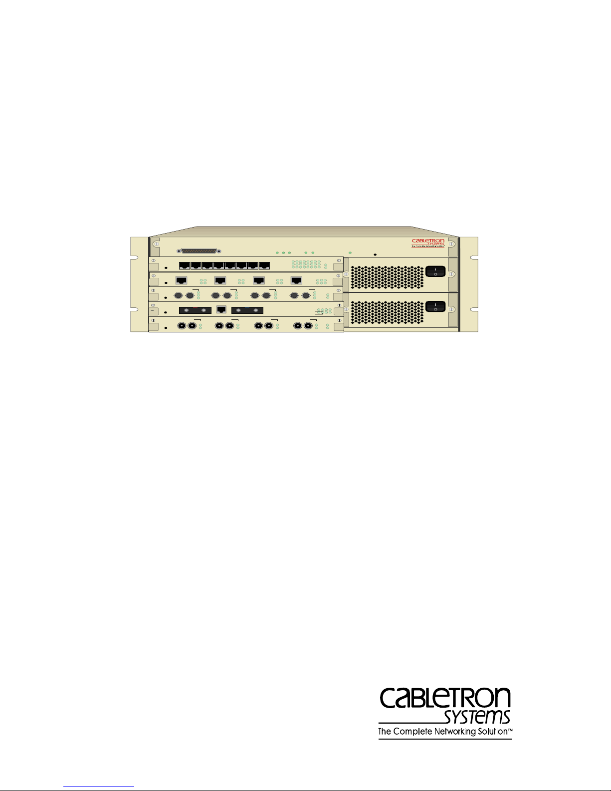
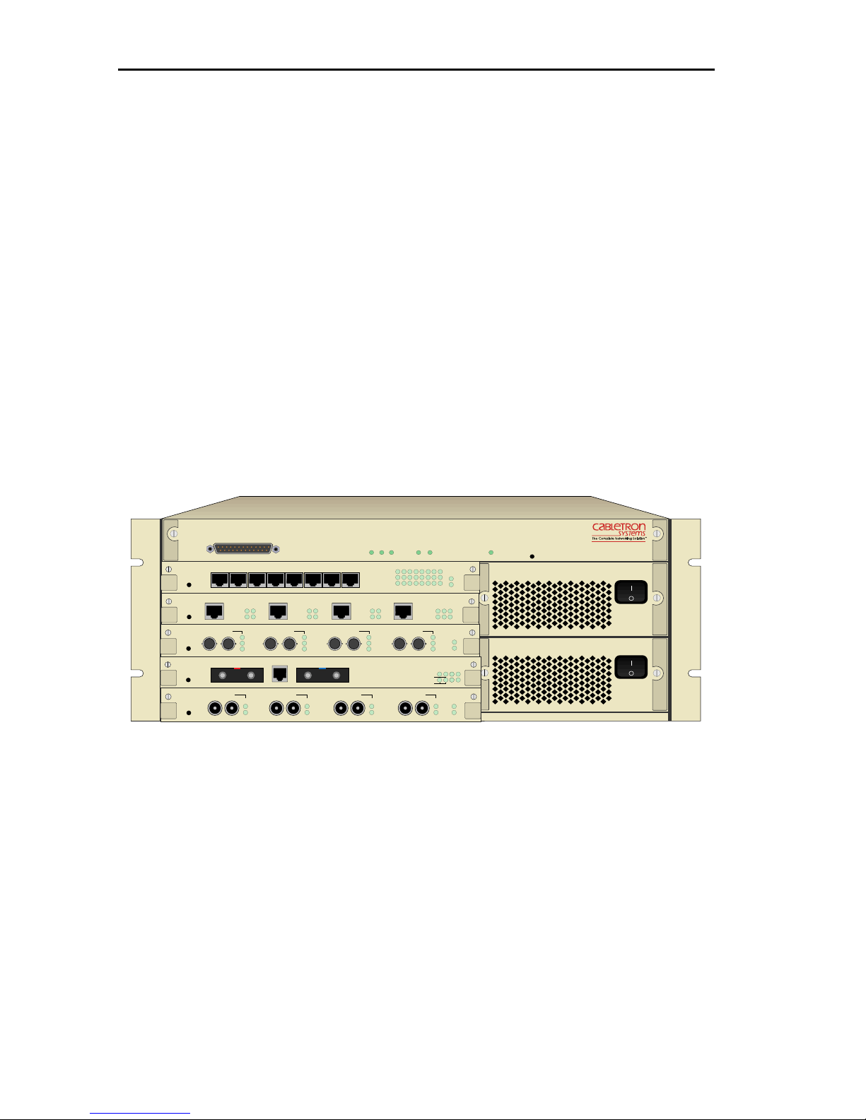
The ATX has five slots for various interface modules and space for
two power supplies. The ATX front panel is shown in Figure 1-1.
TM
PACKET PROCESSING ENGINE
QUAD IEEE 802.3 / ETHERNET 10BASE2
SEGMENT 4SEGMENT 3SEGMENT 2 SEGMENT 1
RXTXRXTXRX
PROCRX
TX
PWR
TX
OFFLINE
FastNET ATX
SEGMENT
OFFLINE
OFFLINE
OFFLINE
TX RX
OFFLINE
OFFLINE
POWER STATUS
ENGINE STATUS
NMS PORT
3X 4X 5X 6X 7X 8X2X1X
RING 1
RX ST
TX 16 TX 16 TX 16 TX 16 PWR
TX
RX
LK
FDDI MIC A FDDI MIC BOPTICAL BYPASS
MULTI-MODE MULTI-MODE
TX
RING 2
RX ST
TX
RX
LK
TX RX TX RX TX RX
RX
TX
TURBO STATUS
OCTAL IEEE 802.3 / ETHERNET 10BASE-T
LINK
ACT
COL
12345678
QUAD IEEE 802.5 TOKEN RING (UTP)
RING 3
RX ST
QUAD FAST ETHERNET / 802.3 100BASE-FX
SEGMENT 4SEGMENT 3SEGMENT 2 SEGMENT 1
TX
RX
LK
QUAD IEEE 802.3 / ETHERNET 10BASE2
SEGMENT 4SEGMENT 3SEGMENT 2 SEGMENT 1
RX
TX
SUPPLY A
POWER
INTELLIGENT FDDI
RING A
RING B
SUPPLY B
RING 4
RX ST PROC
TX
RX
LK
THRU
RX
TX
PROC
PWR
PROC
WRAP
TX PWR
PROCRX
1.6 Gbps
RESET
PWR
PROC
RX
PWR
Figure 1-1. The ATX Front Panel
1.6 ATX FEATURES
Cabletron Systems ATX is designed to meet the growing demands
for bandwidth across the enterprise-wide network. The ATX
integrates the functions of a translation bridge, router, and
concentrator/repeater into a single unit. It is designed to support
multiple independent networks which are internally bridged
and/or routed together with the level of reliability required of
mission-critical networks. The internetworking function is
performed by a high performance RISC processor-based Packet
1-6
Page 21

Introduction
Processing Engine.
The ATX offers features which allow you to easily manage and
maintain your network, such as:
• Protection against multicast storms.
• Data flow control based on packet filters that you define.
• Compilation of statistics for traffic generated by each user
device connected to an ATX segment.
• Ping and Trace Route provide the ATX with the ability to execute
(through LCM) ping and trace route commands which show
router hops, IP interfaces each packet must traverse and how
much time elapsed between transmit and response of a ping
command. For additional information on Ping commands, see
section 3.13, Ping Commands. For additional information on
Trace Route, see section 3.14, Trace Route Commands.
• Power supplies and input/output modules that can be swapped
without disrupting operation of the ATX.
• Configuration and management using the Simple Network
Management Protocol (SNMP) with either an in-band or out-ofband connection.
The ATX includes many functions presently available only in
bridges or routers. It offers much greater throughput to users, since
each module is an independent network and the traffic from a
module or network is not repeated to the others as is done in many
hubs.
As a bridge, the ATX provides high throughput for each network
connected to its ports, translates user-selected packets, and
implements the IEEE and IBM Spanning Tree protocol.
As a router, the ATX implements a suite of IP routing protocols,
including IP, ARP, Reverse ARP, Proxy ARP, RIP, and IP multicasts.
The ATX also implements IPX routing using RIP and SAP.
Additionally it implements AppleTalk Phase II routing.
1-7
Page 22

Introduction
With an innovative, multiple RISC processor architecture, the
ATX’s Packet Processing Engine is capable of filtering and
forwarding at full line speed. Further, the ATX’s protocolindependence and high performance allow for transparent, plugand-play network operation. The ATX offers all the benefits of
interconnecting LANs across a backbone with an increase in
performance over existing bridges.
1.6.1 Netbios Name Caching
The ATX provides the capability of transforming certain Netbios
broadcast frames into non-broadcast frames. The specific frames
handled by Netbios Name Caching are those which seek to locate
another netbios station. These include Datagrams, Name Query,
and Name Recognized frames. For Netbios Name Caching to
function, it must be enabled on all ports for which Netbios traffic
exists.
When the ATX receives any of these frames and Netbios Name
Caching is enabled on the port the frame was received on, the ATX
will identify the frame as a special Netbios Name Caching frame.
Once identified, a couple of actions takes place. First, the ATX
learns the Source Netbios name, the MAC address of the source
workstation, which port the station lives on and any applicable RIF
information. Second, the ATX determines if the destination
Netbios name has been learned. If the Netbios name is learned,
then the ATX replaces the broadcast address with the learned
unicast address, constructs an appropriate RIF is applicable, and
directs the frame to the appropriate port.
The ATX posseses name caching, the ability to reduce the amount
of broadcasts of certain Netbios session initialization frames.
Name Caching works by using certain frames (Name_Query
request and Name_Recognized response) within the Netbios
architeture to identify workstation names and their respective
hardware MAC address. Once the ATX identifies a workstation
and its hardware MAC address, the workstation no longer needs
to flood broadcasts to locate a particular destination on the
network; the ATX replaces the broadcast address with the learned
1-8
Page 23

Introduction
unicast address.
Name_Query_Request frames provide the ATX with the name of
the source workstation, the MAC address, the port which recieved
the frame and any applicable RIF information. The
Name_Recognized_Response provides the ATX with information
including the name of the workstation, the MAC address of the
workstation and any applicable RIF information.
Note: If cached information on the originating workstation has not timed
out, the Name_Recognized will be a directed response instead of an
all-stations broadcast. If the workstation name has not timed out
from the Netbios Name Cache, the next Name_Query frame
destined for either workstation is sent as a directed frame instead of
a single route broadcast.
1.6.2 ATX Local and Remote Port Mirroring
Port mirroring allows the ATX LAN switch to redirect network
traffic (excluding MAC layer errors) from one or more ports to any
other port, in effect “mirroring” all network traffic to a selected
port. This feature allows customers who have existing investments
in external analyzers, external RMON probes, or devices like
Network General’s Distributed Sniffer System to continue to
receive expert analysis and packet decode functions in a switched
environment - simply use the port mirroring function to mirror
switched traffic to the designated “diagnostic” port to which the
analyzer is attached.
The ATX LAN Switch supports local and remote port mirroring.
Local port mirroring is when the diagnostic port is on the same
ATX as the mirrored ports. Remote port mirroring is when the
diagnostic port is on a different or remote ATX from the mirrored
ports. The mirrored ports have to be either local or remote to the
diagnostic port, not both. In the case of remote mirroring, the
traffic from the mirrored ports is encapsulated into an IP packet
and sent to the IP destination defined (the diagnostic port). See
section 3.11 Local and Remote Port Mirroring Commands for
additional information on Port Mirroring commands.
1-9
Page 24

Introduction
1.6.3 IPX with Token Ring Source Routing
Token ring networks often interconnect with source routing (SR)
bridges. Although the source routing is a MAC layer feature, all
packets must provide the correct source route information to the
bridges in order to traverse the networks. To successfully and
efficiently route network traffic in such environments, routers need
to have the capability to explore and select routes, cache and age
route information, and construct network packets with the proper
route information. Support of IPX over source routing (IPX SR)
enables the ATX LAN switch to achieve this capability and route
IPX packets through SR bridges.
Source Route Comands for additional information on source routing
commands.
See section 3.11 IPX Routing Over
1.6.4 Event Logging on the ATX
Event Logging is an ATX troubleshooting tool. It records selected
classes of networking events then analyzes the log of events
recorded to assist in diagnosing problems on the network. ATX
Event Logging includes the following features:
• Separate enabling flags for each event or class of events. The
enabling flags are symbolic and are thus easily used in
troubleshooting the network.
• Continuous monitoring of events is supported.
• Logging entries are easy to add and delete from the source code.
• The framework is integrated with SNMP and easily fits into the
anticipated fault/alarm restructuring.
See section 3.14 Event Logging Commands for additional
information on Event Logging.
1.6.5 ATX LAN Switch Workgroups
Virtual workgroups allow you the flexibility to control broadcasts
in the network. By reducing broadcasts throughout the network, it
1-10
Page 25

Introduction
preserves network bandwidth for important user data and frees up
valuable end station processing. By defining virtual workgroups,
broadcasts will only be seen by other end stations within the same
virtual workgroup. With the functionality to define workgroups by
port grouping, IP network address and/or IPX network number, a
station can be part of multiple workgroups based on their location
and protocol.
Each workgroup can be defined by port, IP network address
and/or IPX network number. A total of 100 virtual workgroups
can be defined on each ATX LAN Switch. The ATX LAN Switch
can route between IP workgroups but all other workgroups will
need an external router (See Workgroup to Workgroup
Communication). For additional information, see section 3.8
Virtual Workgroup LCM Commands.
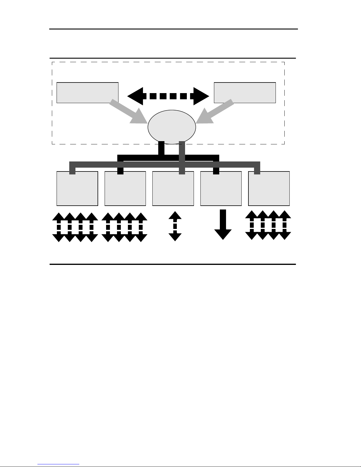
1.6.6 ATX Packet Processing Engine
The ATX architecture, diagrammed in Figure 1-2, is based on dual
29030 RISC processors on the Packet Processing Engine version
3(PPE-3). In addition, it includes the following:
• At least one RISC processor per i/o module
• Backplane providing 1.6 Gbps capacity, with a load balancing
architecture for maximum accessibility for I/O modules
• A 2mb shared RAM architecture, which is optimized using
adaptive buffer allocation. Adaptive Buffer Allocation (ABA) is
an algorithm providing a sophisticated distribution of packet
buffering to meet varied utilization demands per port.
1-11
Page 26
Introduction
Packet Processing Engine
Main Processor
AMD 29030 RISC CPU
Dual Synchronous Protocol Independent Bus
RISC
PROCESSOR
4 SEGMENT
ETHERNET
4 Segments 4 Segments Dual Ring Multiple
DUAL RISC
PROCESSOR
FDDI
FAST
ETHERNET
SYNCHRONIZATION
1.6 Gbps
SHARED
MEMORY
RISC
PROCESSOR
Turbo Processor
AMD 29030 RISC CPU
RISC
PROCESSOR
Emerging
Technologies
Segments
DUAL RISC
PROCESSOR
4 SEGMENT
TOKEN RING
4 Rings
Figure 1-2. ATX Architecture
1.6.7 Input/output Modules
The ATX has four types of modules available. The modules slide
into the face of the ATX. The module installation procedures are in
Chapter 8.
The ATX supports the following:
• 3E02-04, 3E05-04, 3E07-04, 3E08-04, and 3E02-08-ATX - Multisegment Ethernet modules that come in five models-four UTP
10BASE-T connections, four AUI connections, four BNC
10BASE-2 connections, four fiberoptic 10BASE-FL connections,
and eight UTP 10BASE-T connections respectively.
1-12
Page 27

Introduction
• 3T02-04, 3T05-04 and 3T01-04 - Four ring Token Ring modules
accepting data frames from and sending data frames to four
Token Ring networks. The 3T02 and 3T01 modules support UTP
and STP cable types respectively, while the 3T05 supports either
UTP or STP.
• 3F00-01 and 3F55-01 - DAS (dual-attached station) FDDI
modules. These modules transfer packets from and to a FDDI
network. The front panel accepts media interface connectors
(MICs) for multi-mode fiber (MMF) such as the 3F00-01, or
single mode fiber (SMF) such as the 3F55-01. Both modules
support an external optical bypass switch (OBS). Each has a
built-in DMA controller, but not a general purpose processor, so
the station management functions are performed by the PPE.
• 3H02-04 and 3H08-04 - Four port 100 Mbps Fast Ethernet Switch
modules. These modules support UTP via RJ71 connectors and
fiberoptic via ST connectors respectively.
Modules are described in greater detail in the documentation that
accompanies each module.
1.6.8 Power Supply
The ATX comes with one self-ranging power supply. An optional
redundant power supply is also available that automatically takes
over when the primary power supply fails. Each power supply has
its own power entry module and fuse assembly to allow the use of
separate power sources. When both supplies are used the load is
balanced between the power supplies.
1.7 BRIDGING FUNCTIONS
The basic bridging function of an ATX is to transparently forward
data packets to the network segments (LANs) it interconnects.
Incoming packets are stored momentarily while the ATX checks
their destination addresses against the ATX's address table. If a
packet's destination address is not on the same network segment
1-13
Page 28

Introduction
as the originating packet, the ATX immediately forwards the
packet to the segment associated with the destination address.
Local traffic, data packets whose source and destination address is
on the same segment, is automatically discarded.
The ATX forwards data packets to network segments based on the
IEEE 802.1D spanning tree algorithm, which converts multiple
LANs into a “spanning tree” of networks. This standard defines a
logical (not physical) network configuration consisting of one
extended LAN without active duplicate paths between ATXs. The
ATX and other spanning tree compliant bridges in the network
dynamically configure the network topology into a single
spanning tree by exchanging bridge protocol data units (BPDUs).
In a parallel configuration of bridges packets are forwarded to
LANs by only one ATX (or other spanning tree compliant bridge).
When there are multiple ATXs between two LANs, only one of the
ATXs forwards any individual packet. The spanning tree
algorithm determines which ATX should forward each packet.
Packets originating from one device and destined for a remote
device are forwarded in the same order in which they are received.
Each port of the ATX can be configured for transparent (802.1d)
bridging, IBM source routing bridging, or source routing
transparent bridging (802.5M). Depending on network topology, it
may be desirable to include a mix of these methods within a single
ATX.
The choice of bridging methods is determined both by end station
requirements and by other internetworking equipment.
Source routing end stations may use any of the ATX three bridging
methods. Transparent end stations must use either transparent or
SRT bridging. When in doubt, transparent bridging is the easiest to
configure and use.
If redundant links are employed along with IBM source routing
bridges, then the attached ATX port should be configured for
source routing. This will enable the mesh of bridges to derive a
spanning tree suitable for spanning tree explorer frames and for
1-14
Page 29

Introduction
multicast packets.
If source routing is desired, and either Ethernet or FDDI is to be
used as a backbone between Token Rings, then the Ethernet or
FDDI port should be configured for SRT bridging. (SRT over
Ethernet is not a standard, but is available for use between
multiple ATX chassis in backbone applications. In this case, the
“Ethernet” may actually be a microwave or satellite link with an
Ethernet-like interface.)
A common mixture of bridging modes may occur when Ethernet
segments and Token Ring segments do not exchange data but
share an FDDI backbone. In this case, the Ethernets may be
configured for transparent bridging, the Token Rings for source
routing, and the FDDI backbone for SRT. (Don't infer from this
example that SRT is the sum of transparent and source routing
bridging; it is a distinct third method).
The bridging method is dependent on the configuration of the
bridge entry and exit ports, and the value of the Routing Indicator
(RII) bit in the received frame. The following chart summarizes the
interaction between the bridging method.
Exit Port Configuration
Entry
Port
Config.
SRT 0 spanning tree block spanning tree
SR 0 block block block
TST 0 spanning tree block spanning tree
RII
1 source route source route spanning tree
1 source route block block
SRT
(Source
Routing
Transparent)
SR
(Source
Routing)
TST
(Transparent
Spanning
Tree)
a
1 spanning tree
a. source address is not learned
a
block spanning tree
a
1-15
Page 30

Introduction
1.7.1 Transparent Bridging
Transparent or spanning tree bridging requires no initial
programming. After being installed on the network, bridges
“learn” and remember the location of the attached devices by
reading the source addresses of incoming packets. Then they place
the source address and port information in a lookup table.
When a packet comes into a port, the bridge reads the destination
address and attempts to find the location of the destination node
using its lookup table. If the address is in the table, the bridge
simply re-transmits the packet out of the appropriate port. If the
address is not found in the table the bridge re-transmits the packet
out of all the ports except the source port.
Transparent or spanning tree bridges also usually provide some
packet filtering capabilities. On some networks it is desirable to
prevent certain stations from accessing other segments. The ATX
uses this bridging method.
1.7.2 Source Route Translational Bridging
Source Route Translational Bridging (SRTB) allows the ATX to strip
and cache routing information for source route frames. Routing
information (RIF) is used in source route networks to indicate the
path a frame has taken through the network. This feature will
enable the ATX to switch between source route only networks like
Token Ring and transparent networks like Ethernet and FDDI. RIF
is not supported on Ethernet networks and is seldom used on
FDDI networks. In order to merge source routed Token Ring
networks with transparent Ethernet and FDDI networks the ATX
must strip the RIF when communicating to Ethernet or FDDI and
insert the RIF when communicating back to Token Ring. SRTB on
the ATX contains the following features:
• A redundant/load sharing source route network is NOT
supported when SRTB (RIF caching) is enabled. A
redundant/load sharing source route network could have
multiple paths to the transparent network and cause the
1-16
Page 31

Introduction
learning database to learn addresses on the incorrect ports. This
could result in frames not getting forwarded and loss of
communication.
• SRTB is a global parameter and is enabled only on Token Ring
ports with SRT bridging mode.
• The RIF database supports 8,192 entires.
• SRTB can be enabled based on IP, IPX and other protocols (SNA,
NetBIOS, etc.)
• All existing protocol translations (IP, IPX, SNA, NetBIOS and
AppleTalk) are supported when SRTB is enabled.
• The RIF caching aging timer is the same as the Spanning Tree
timer, and is configurable. The default value is 300 seconds.
• The RIF cache entry is relearned based on a separate timer that
is set to one half the Spanning Tree timer.
1.7.3 Source Routing Bridging
Source routing bridging (SR) is an alternative to transparent or
spanning tree bridging, and is widely used in Token Ring
networks. The ATX supports source routing bridging on Token
Ring LANs, and an enhancement to source routing called SRT on
all LANs.
With source routing bridging, all networked devices participate in
the source routing protocol. Each packet that crosses a bridge
specifies the originator's LAN segment, the particular bridge, and
the destination LAN segment. It may also specify intermediate
LAN segments and bridges.
1-17
Page 32

Introduction
Station A Station CBridge B
Ring
7
data packet
address 43 B 7 data
Figure 1-3. Source Routing Example
Ring
43
In the example in Figure 1-3, a data packet traveling from station C
on LAN 43 through bridge B to station A on LAN 7 must specify
the full route it is to take. The source station is responsible for
specifying the route, hence the term “source routing.”
Bridges in a source routing network must be configured with the
LAN numbers (normally 1 to 4095) to which it is connected and a
bridge number (normally 1 to 15). The network administrator
chooses the numbers; the LAN numbers must be unique in the
source routed network and the bridge numbers must be unique
between each pair of LANs.
Source routing workstations need not be configured with route
information; instead they discover the best route to a destination
through the use of explorer frames. In the Figure 1-3 example,
station C might first transmit an empty explorer frame. Bridge B
would add 43-B-7 as its portion of the route, and then transmit the
explorer on all other LANs. When the packet reaches station A, it
can reverse the route to send a reply back to C. When C receives
the reply, both stations have all of the routing information needed
to converse, with no further explorer frames needed.
Part of the original intent of source routing bridging was to enable
LANs to be richly connected by low-performance, low-cost
bridges. As shown in Figure 1-4, source routing allows an end
station to choose a less-congested path through a chain of bridges,
1-18
Page 33

where each bridge is likely to become congested.
Introduction
Station A
Congested
Alternative Route
Figure 1-4. Data Path Using Source Routing Bridging
Station C
In contrast to spanning tree bridging, all bridges and all links are
active with source routing bridging; the least-congested path is
chosen at discovery time. With products like the ATX, such
congestion avoidance is rarely necessary, since the bridge is
capable of handling nearly any traffic load without experiencing
congestion.
1.7.4 Source Routing Transparent Bridging
Source Routing Transparent (SRT) bridging is a method that
merges IBM-style source routing with transparent spanning tree
bridging. If a route is present in a packet, then the bridge uses it;
otherwise the bridge applies transparent learning rules. It
represents an attempt by the IEEE standards committee to
standardize source routing and correct some shortcomings in
source routing (notably multicast transmission). IEEE has defined
SRT bridging for Token Rings, and ANSI has incorporated it into
the FDDI standards. The ATX supports SRT bridging on these, as
well as on Ethernet (for Ethernet, there is no such standard; the
ATX provides this as a proprietary backbone service).
1-19
Page 34

Introduction
1.7.5 Translation
The ATX is a translating bridge; meaning it translates packets
across unlike protocols. For example, if an Ethernet (802.3) data
packet is to be forwarded to an FDDI segment, the ATX translates
the packet to FDDI packet format. Conversely, the ATX translates
FDDI packets to be forwarded to an Ethernet segment to Ethernet
(802.3) packet format. This means the ATX can transparently
exchange data packets between FDDI and Ethernet LANs.
A translation parameter was added to the ATX Token Ring module
to complete the StripRIF protocol set, StripRIF ALL. The current set
of protocols that StripRIF is used for are: IPX, ARP, NetBIOS and
SNA. This feature allows the ATX to handle protocols which need
the RIF stripped before being transmitted out other ATX LAN
switch ports (for example, protocols such BootP and RIP). For
addtional information on StripRIF commands, see the section 1.10
Basic LCM Commands.
For example, in Figure 1-5 workstation 100 on Ethernet LAN 1 is
able to access server F1, which is attached directly to the FDDI
ring, or server E1 on Ethernet LAN 2. To reach either server, the
Ethernet packet from workstation 100 is translated by ATX A to a
FDDI format. To reach server E1, the packet is translated by ATX B
back into Ethernet format.
Server E1
ATX B
ES/1 B
Workstation 100
Ethernet LAN 1
ES/1 A
ATX A
FDDI ring
Server F1
Ethernet LAN 2
Figure 1-5. Network Where Translation Must Occur
1-20
Page 35

Introduction
The ATX uses a standardized internal format called canonical
format, for packet translation. (Refer to Appendix B, Packet
Translation Procedure for an explanation of the packet translation
procedure.) The ATX converts all incoming packets into its internal
format and then converts each packet from its internal format to
either FDDI, Ethernet, or Token Ring format, depending on the
packet's destination.
The ATX can interoperate with other vendors' translating bridges.
Translation allows end-nodes to reach destinations on the FDDI
ring as well as destinations attached to other vendors' translating
bridges and routers. In Figure 1-5 for example, ATX A or ATX B
could be bridge products from other vendors.
1.8 ROUTING FUNCTIONS
The ATX can route packets that use the IP and IPX, and Appletalk
protocols. A brief overview of these follows. For more in-depth
discussions, refer to the books listed in the section, Related
Documentation.
Note: When the ATX is not configured for routing, it’s necessary to
establish a default gateway so that management can take place
using a SNMP agent. To establish a default gateway connection,
apply the route add command through LCM using the following
format: route add IPaddr Gwaddr PORT# [hops]
[IPmask].For example: route add 0.0.0.0
176.16.107.19 3 This command establishes port 3 as the
default gateway to the router at 176.16.107.19. Any port (2 to 41)
can be the default gateway. The IPaddr 0.0.0.0 signals that this is
the default gateway specification. Other addresses can be used to
explicitly and statically route some IP trafic while remaining in
bridging (rather than routing) mode. SNMP management stations
are now able to poll the ATX locally and remotely, but this does not
permit the ATX to send SNMP traps to multiple SNMP
management stations. To identify a specific SNMP management
station where traps are sent, change the [configNMSAddress] MIB
located in the MIB tree at:
1-21
Page 36

Introduction
private/enterprise/sigma/ecs1/admin/config. The default setting for
this MIB is 0. Query the MIB and change this value to the address
of the SNMP management station, then SET. If the
[configNMSAddress] MIB is not changed, traps are sent to the last
SNMP manager which polled the device.
1.8.1 IP Routing
IP routing allows end-nodes to send packets to end-nodes
elsewhere on the network using the IP protocol suite. The ATX
builds an IP routing table that stores destination addresses, the
address of the gateway through which that destination can be
reached, and the number of hops it takes to get there. (The number
of hops is the number of other routers or gateways a packet must
go through to get to the gateway.) The routing table allows the ATX
to know how to route a packet to reach its destination address.
The routing table is a dynamic table, meaning that entries are
continually being added and timed-out based on information the
ATX is receiving.
Routing Information Protocol (RIP)
RIP is one of the protocols that allows the ATX to build an accurate,
current routing table. Routers, including the ATX, send out
broadcasts every 30 seconds advertising the networks they know
about, the routes to those networks, and the number of hops to get
there. In this way the ATX is constantly up-to-date on the state of
its neighboring networks.
Address Resolution Protocol (ARP)
ARP provides a method for mapping IP addresses to physical
hardware addresses. When a device wants to communicate with
another device whose hardware address it doesn’t know, it sends
out an ARP request. An ARP request contains the IP and hardware
addresses of the source, and the IP address of the potential
1-22
Page 37

Introduction
destination device. If the device is on the network, it will respond
with its hardware address.
Reverse Address Resolution Protocol (RARP)
If the ATX is not configured with an IP address, it uses reverse ARP
(RARP), to send out broadcasts of its physical hardware address to
find its IP address.
Proxy ARP
Proxy ARP provides a mechanism whereby the ATX can respond
to an ARP request on behalf of a device that is located on a
network behind it. This is particularly helpful if you are using IP
subnetting. The ATX could respond to a request on behalf of
devices that it knows about, in effect acting as a proxy agent for
that device.
BOOTP
The BOOTstrap Protocol (BOOTP) uses IP to deliver a packet
including an IP address, the address of a router and the server
address. Enabling the BOOTP relay option is useful in
environments where you have a diskless client and its server is on
a network on the other side of the ATX. When the client boots up, it
sends out a broadcast requesting the software it needs to
download. If bootp is not enabled, the ATX won’t forward the
broadcast to the network where the server is located. This may also
be used to relay DHCP frames.
IPM
Enable IP multicasting. IP multicasting is the transmission of IP
packets to a host group. A host group is a set of hosts identified by
a single IP address.
1-23
Page 38

Introduction
1.8.2 Multiple IP Networks Per Port
The ATX’s routing software allows you to configure a single IP
network to span multiple physical network segments (ATX ports).
This enables you to configure multiple physical networks as one
logical network.
FastNET ATX
NMS PORT
SEGMENT
3X 4X 5X 6X 7X 8X2X1X
OFFLINE
RING 1
RX ST
TX 16 TX 16 TX 16 TX 16 PWR
OFFLINE
TX
RX
LK
OFFLINE
TX RX
FDDI MIC A FDDI MIC BOPTICAL BYPASS
MULTI-MODE MULTI-MODE
OFFLINE
QUAD IEEE 802.3 / ETHERNET 10BASE2
SEGMENT 4SEGMENT 3SEGMENT 2 SEGMENT 1
RXTXRXTXRX
PROCRX
TX
PWR
TX
OFFLINE
TX
OFFLINE
POWER STATUS
ENGINE STATUS
OCTAL IEEE 802.3 / ETHERNET 10BASE-T
LINK
ACT
COL
QUAD IEEE 802.5 TOKEN RING (UTP)
RING 2
RING 3
RX ST
RX ST
QUAD FAST ETHERNET / 802.3 100BASE-FX
TX
TX
RX
RX
LK
LK
TX RX TX RX TX RX
QUAD IEEE 802.3 / ETHERNET 10BASE2
RXTXRXTXRX
TURBO STATUS
12345678
SEGMENT 4SEGMENT 3SEGMENT 2 SEGMENT 1
SEGMENT 4SEGMENT 3SEGMENT 2 SEGMENT 1
SUPPLY A
SUPPLY B
POWER
PROC
PWR
RING 4
RX ST PROC
PROC
TX
RX
LK
PWR
INTELLIGENT FDDI
THRU
PROC
WRAP
RX
RING A
RING B
TX PWR
PROCRX
PWR
TX
TM
1.6 Gbps
RESET
PACKET PROCESSING ENGINE
1
Physical Networks
3
2
Engineering Engineering Engineering
Logical Network A
Figure 1-6. One Logical Network On Multiple Physical Networks
The ATX also allows you to assign multiple IP network addresses
to one physical network segment (ATX port). This feature allows
you to configure two or more logical networks on the same
physical network segment. If the hosts on a physical network
segment exceed the current logical network’s capacity, you can
easily add another logical network to the physical network
segment.
1-24
Page 39

Introduction
In addition, by overlapping logical networks, a user who moves to
another physical network segment can remain on the same logical
network and retain their net/host IP address, even if he or she is
sharing the new physical network segment with other logical
networks. This is known as address mobility and is a useful Virtual
LAN component that can ease adds, moves, and changes and the
definition of broadcast domains.
FastNET ATX
NMS PORT
SEGMENT
3X 4X 5X 6X 7X 8X2X1X
OFFLINE
RING 1
RX ST
TX 16 TX 16 TX 16 TX 16 PWR
OFFLINE
TX
RX
LK
OFFLINE
TX RX
FDDI MIC A FDDI MIC BOPTICAL BYPASS
MULTI-MODE MULTI-MODE
OFFLINE
QUAD IEEE 802.3 / ETHERNET 10BASE2
SEGMENT 4SEGMENT 3SEGMENT 2 SEGMENT 1
RXTXRXTXRX
PROCRX
TX
PWR
TX
OFFLINE
TX
OFFLINE
POWER STATUS
ENGINE STATUS
OCTAL IEEE 802.3 / ETHERNET 10BASE-T
LINK
ACT
COL
QUAD IEEE 802.5 TOKEN RING (UTP)
RING 2
RING 3
RX ST
RX ST
QUAD FAST ETHERNET / 802.3 100BASE-FX
TX
TX
RX
RX
LK
LK
TX RX TX RX TX RX
QUAD IEEE 802.3 / ETHERNET 10BASE2
RXTXRXTXRX
TURBO STATUS
12345678
SEGMENT 4SEGMENT 3SEGMENT 2 SEGMENT 1
SEGMENT 4SEGMENT 3SEGMENT 2 SEGMENT 1
SUPPLY A
SUPPLY B
POWER
PROC
PWR
RING 4
RX ST PROC
PROC
TX
RX
LK
PWR
INTELLIGENT FDDI
THRU
PROC
WRAP
RX
RING A
RING B
TX PWR
PROCRX
PWR
TX
TM
1.6 Gbps
RESET
PACKET PROCESSING ENGINE
Physical Network
A - Engineering B - Manufacturing
Logical Network A, B, and C
C - Administration
Figure 1-7. Multiple Logical Networks On One Physical Network
When assigning multiple IP network addresses to an ATX port, the
port must be configured for routing. In addition, the logical
networks connected to an ATX must see the ATX as a
gateway(router). The way a host accomplishes this is dependent
1-25
Page 40

Introduction
upon the operating system or TCP/IP being used. The host
becomes aware of a gateway in one of three ways:
• The host is manually configured with a default gateway
address.
• The host is listening to Routing Information Protocol (RIP)
broadcasts.
• The host is participating in the router discovery protocol
(ICMP).
When using LCM each ATX port can be configured for zero or
more IP addresses, with associated subnet masks. Each IP address
defines an IP subnetwork. Each IP subnetwork is a distinct entity
with respect to protocols, such as RIP (Routing Information
Protocol), and is treated as a separate interface. Specifically:
• RIP advertisements are transmitted to each IP subnetwork
broadcast address of the IP addresses associated with a ATX
port. RIP advertisements include route descriptions of the other
IP subnetworks assigned to that ATX port. For example, if a ATX
port has three IP addresses assigned to it, three RIP
advertisements are transmitted each interval, and each RIP
advertisement publicizes the other two IP subnetworks.
• Router discovery ICMP packets are transmitted to either the
host’s IP multicast address, or to the local broadcast address,
regardless of how many IP addresses are assigned to an ATX
port. All IP subnetworks assigned to an ATX port are advertised
in each router discovery ICMP packet.
1.8.3 IP Multicast Routing
The Internet Protocol (IP) is recognized as the base technology for
multimedia applications.The implementation of IP multicast
routing complies with the DVMRP standard.
In general, IP multicasting is the transmission of IP packets to a
host group. A host group is a set of hosts identified by Class D IP
1-26
Page 41

Introduction
addressing (i.e., those IP addresses with 1110 as their high-order
four bits). Using Internet standard dotted decimal notation, host
group IP addresses range from 224.0.0.0 to 239.255.255.255. The IP
address 224.0.0.1 is assigned to the permanent group of all IP
hosts.
Members of a host group can:
• Join and leave the host group at any time
• Be included as a member in multiple host groups.
A host group can be permanent or temporary. A permanent host
group maintains a single IP address regardless of how many
members it has. A temporary host group is one that must have at
least one member, a permanent host group can exist with zero
members. Currently the ATX supports only temporary host
groups.
Note: There are no restrictions on the location or number of members
assigned to a host group.
IP multicasting provides the following benefits:
• When the same information must be sent to more than one
destination, IP multicasting reduces both network overhead and
the time it takes for all destinations to receive the information.
• When information must be sent to one or more hosts whose
address is either unknown or changeable, IP multicasting can
reduce the need for complicated configuration files because
permanent host groups maintain a single IP address.
Group membership reports are not forwarded across the network.
Instead, routers learn of the existence of other routers on the
network, and forward all IP multicast packets to the downstream
neighboring router.
When a route receives an IP multicast packet, it verifies the route’s
origin, and then forwards the IP multicast packet only if there is a
downstream neighboring router and/or there is a host group
member on the outgoing port.
1-27
Page 42

Introduction
For example, in Figure 1-8, LANs B, C, and D are bridged to
backbone LAN A. A packet originating from LAN C destined to
the host group member on LAN B will traverse LANs C and A but
not LAN D. Similarly, an IP multicast packet destined to the group
member on LAN B that originated on that LAN will not be
forwarded to the other LANS.
LAN A
FastNET ATX
NMS PORT
SEGMENT
3X 4X 5X 6X 7X 8X2X1X
OFFLINE
RING 1
RX ST
TX 16 TX 16 TX 16 TX 16 PWR
OFFLINE
TX
RX
LK
OFFLINE
TX RX
FDDI MIC A FDDI MIC BOPTICAL BYPASS
MULTI-MODE MULTI-MODE
OFFLINE
QUAD IEEE 802.3 / ETHERNET 10BASE2
SEGMENT 4SEGMENT 3SEGMENT 2 SEGMENT 1
RXTXRXTXRX
PROCRX
TX
PWR
TX
OFFLINE
TX
OFFLINE
POWER STATUS
OCTAL IEEE 802.3 / ETHERNET 10BASE-T
QUAD IEEE 802.5 TOKEN RING (UTP)
RING 2
RING 3
RX ST
RX ST
QUAD FAST ETHERNET / 802.3 100BASE-FX
TX
TX
RX
RX
LK
LK
TX RX TX RX TX RX
QUAD IEEE 802.3 / ETHERNET 10BASE2
RXTXRXTXRX
ENGINE STATUS
TURBO STATUS
SUPPLY A
SUPPLY B
POWER
LINK
ACT
COL
12345678
RX ST PROC
SEGMENT 4SEGMENT 3SEGMENT 2 SEGMENT 1
TX
RX
LK
INTELLIGENT FDDI
RING A
RING B
SEGMENT 4SEGMENT 3SEGMENT 2 SEGMENT 1
TX
TM
1.6 Gbps
RESET
PACKET PROCESSING ENGINE
PROC
PWR
RING 4
PROC
PWR
THRU
PROC
WRAP
RX
TX PWR
PROCRX
PWR
FastNET ATX
NMS PORT
SEGMENT
OFFLINE
RING 1
RX ST
TX 16 TX 16 TX 16 TX 16 PWR
OFFLINE
TX
RX
LK
OFFLINE
TX RX
FDDI MIC A FDDI MIC BOPTICAL BYPASS
MULTI-MODE MULTI-MODE
OFFLINE
QUAD IEEE 802.3 / ETHERNET 10BASE2
SEGMENT 4SEGMENT 3SEGMENT 2 SEGMENT 1
RXTXRXTXRX
PROCRX
TX
PWR
TX
OFFLINE
TX
OFFLINE
3X 4X 5X 6X 7X 8X2X1X
RING 2
RX ST
TX
RX
LK
TX RX TX RX TX RX
RXTXRXTXRX
POWER STATUS
ENGINE STATUS
TURBO STATUS
OCTAL IEEE 802.3 / ETHERNET 10BASE-T
LINK
ACT
COL
12345678
QUAD IEEE 802.5 TOKEN RING (UTP)
RING 3
RX ST
QUAD FAST ETHERNET / 802.3 100BASE-FX
TX
RX
LK
QUAD IEEE 802.3 / ETHERNET 10BASE2
SUPPLY A
SUPPLY B
POWER
RING 4
RX ST PROC
SEGMENT 4SEGMENT 3SEGMENT 2 SEGMENT 1
TX
RX
LK
INTELLIGENT FDDI
THRU
RING A
RING B
SEGMENT 4SEGMENT 3SEGMENT 2 SEGMENT 1
TX
TM
1.6 Gbps
RESET
PACKET PROCESSING ENGINE
PROC
PWR
PROC
PWR
PROC
WRAP
RX
TX PWR
PROCRX
PWR
LAN B LAN C LAN D
HOST GROUP
MEMBER
Figure 1-8. Bridged LAN With One Host Group Member
In Figure 1-9, a member on LAN C joins the host group. In this
case, IP multicast packets to all host group members on LANs B
and C will again traverse LANs A, B, and C, but not LAN D.
1-28
Page 43

LAN A
Introduction
FastNET ATX
NMS PORT
SEGMENT
3X 4X 5X 6X 7X 8X2X1X
OFFLINE
RING 1
RX ST
TX 16 TX 16 TX 16 TX 16 PWR
OFFLINE
TX
RX
LK
OFFLINE
TX RX
FDDI MIC A FDDI MIC BOPTICAL BYPASS
MULTI-MODE MULTI-MODE
OFFLINE
QUAD IEEE 802.3 / ETHERNET 10BASE2
SEGMENT 4SEGMENT 3SEGMENT 2 SEGMENT 1
RXTXRXTXRX
PROCRX
TX
PWR
TX
OFFLINE
TX
OFFLINE
POWER STATUS
RING 2
RING 3
RX ST
RX ST
TX
TX
RX
RX
LK
LK
TX RX TX RX TX RX
RXTXRXTXRX
ENGINE STATUS
TURBO STATUS
POWER
OCTAL IEEE 802.3 / ETHERNET 10BASE-T
LINK
ACT
COL
12345678
QUAD IEEE 802.5 TOKEN RING (UTP)
QUAD FAST ETHERNET / 802.3 100BASE-FX
SEGMENT 4SEGMENT 3SEGMENT 2 SEGMENT 1
RING A
RING B
QUAD IEEE 802.3 / ETHERNET 10BASE2
SEGMENT 4SEGMENT 3SEGMENT 2 SEGMENT 1
SUPPLY A
SUPPLY B
RX ST PROC
TX
RX
LK
INTELLIGENT FDDI
TX
TM
1.6 Gbps
RESET
PACKET PROCESSING ENGINE
PROC
PWR
RING 4
PROC
PWR
THRU
PROC
WRAP
RX
TX PWR
PROCRX
PWR
FastNET ATX
NMS PORT
SEGMENT
3X 4X 5X 6X 7X 8X2X1X
OFFLINE
RING 1
RX ST
TX 16 TX 16 TX 16 TX 16 PWR
OFFLINE
TX
RX
LK
OFFLINE
TX RX
FDDI MIC A FDDI MIC BOPTICAL BYPASS
MULTI-MODE MULTI-MODE
OFFLINE
QUAD IEEE 802.3 / ETHERNET 10BASE2
SEGMENT 4SEGMENT 3SEGMENT 2 SEGMENT 1
RXTXRXTXRX
PROCRX
TX
PWR
TX
OFFLINE
TX
OFFLINE
POWER STATUS
OCTAL IEEE 802.3 / ETHERNET 10BASE-T
QUAD IEEE 802.5 TOKEN RING (UTP)
RING 2
RING 3
RX ST
RX ST
QUAD FAST ETHERNET / 802.3 100BASE-FX
TX
TX
RX
RX
LK
LK
TX RX TX RX TX RX
QUAD IEEE 802.3 / ETHERNET 10BASE2
RXTXRXTXRX
ENGINE STATUS
LINK
ACT
COL
TURBO STATUS
12345678
SEGMENT 4SEGMENT 3SEGMENT 2 SEGMENT 1
SEGMENT 4SEGMENT 3SEGMENT 2 SEGMENT 1
SUPPLY A
SUPPLY B
POWER
RX ST PROC
TX
RX
LK
INTELLIGENT FDDI
RING A
RING B
TX
TM
1.6 Gbps
RESET
PACKET PROCESSING ENGINE
PROC
PWR
RING 4
PROC
PWR
THRU
PROC
WRAP
RX
TX PWR
PROCRX
PWR
LAN B LAN C LAN D
HOST GROUP
MEMBER
HOST GROUP
MEMBER
Figure 1-9. Bridged LAN With Two Host Group Members
1.8.4 IP Routing Over Source Routing
FastNET ATX
NMS PORT
SEGMENT
3X 4X 5X 6X 7X 8X2X1X
OFFLINE
RING 1
RX ST
TX 16 TX 16 TX 16 TX 16 PWR
OFFLINE
TX
RX
LK
OFFLINE
TX RX
FDDI MIC A FDDI MIC BOPTICAL BYPASS
MULTI-MODE MULTI-MODE
OFFLINE
QUAD IEEE 802.3 / ETHERNET 10BASE2
SEGMENT 4SEGMENT 3SEGMENT 2 SEGMENT 1
RXTXRXTXRX
PROCRX
TX
PWR
TX
OFFLINE
TX
OFFLINE
POWER STATUS
OCTAL IEEE 802.3 / ETHERNET 10BASE-T
QUAD IEEE 802.5 TOKEN RING (UTP)
RING 2
RING 3
RX ST
RX ST
QUAD FAST ETHERNET / 802.3 100BASE-FX
TX
TX
RX
RX
LK
LK
TX RX TX RX TX RX
QUAD IEEE 802.3 / ETHERNET 10BASE2
RXTXRXTXRX
ENGINE STATUS
LINK
ACT
COL
TURBO STATUS
12345678
SEGMENT 4SEGMENT 3SEGMENT 2 SEGMENT 1
SEGMENT 4SEGMENT 3SEGMENT 2 SEGMENT 1
SUPPLY A
SUPPLY B
POWER
RING 4
RX ST PROC
TX
RX
LK
INTELLIGENT FDDI
THRU
RING A
RING B
TX
TM
1.6 Gbps
RESET
PACKET PROCESSING ENGINE
PROC
PWR
PROC
PWR
PROC
WRAP
RX
TX PWR
PROCRX
PWR
Token Ring networks are often connected by source-routing
bridges. End-stations that communicate across a source-routing
bridging domain must be able to build routes from themselves to
their destinations, specifying the Token Rings to be traversed.
7
Application
Presentation
6
5
Session
Transport
4
3
Network
2
1
Data Link
Physical
Figure 1-10. OSI Reference Model
Source-routing operates at Layer 2
1-29
Page 44

Introduction
The architecture behind source-routing bridges is that a packet
header containing a route is inserted by the source end-station. For
the source end-station to discover a route to a destination endstation, it must learn of a route by transmitting a special type of
packet called an explorer packet.The explorer packet is duplicated
by source-routing bridges as it discovers possible route choices.
A copy of the explorer packet is sent over every possible route.
When a source end-station discovers a route to a destination endstation, it stores the route so that it can be used for subsequent
packets to the same destination end-station. Generally routes are
stored for approximately 15 minutes, or three times the Spanning
Tree age. However, the time can be shorter if the Spanning Tree
topology is changing.
In simplest terms, the data link layer header of a packet on a Local
Area Network (LAN) looks like the following.
destination source data
Figure 1-11. Data Link Layer Packet Header
To distinguish between packets whose data link headers include
routing information and those that do not involves setting the
Routing Information Indicator (RI). The Routing Information Field
(RIF) contains the additional source-routing information.
The RI happens to be the multicast bit in the source field.
Therefore, a packet with a multicast bit set to 0 is not treated as a
source-routing packet. However, if the multicast bit is set, the
information following the usual data link layer header is assumed
to be a source-routing header.
1-30
Page 45

Introduction
destination source data
multicast bit=0 (not a source-routing packet)
destination source dataRI
multicast bit set (source-routing packet)
Figure 1-12. Packet Headers With And Without Source-routing Bit Set
In TCP/IP hosts, an explorer packet exchange is normally
accomplished as part of the Address Resolution Protocol (ARP).
ARP is used to dynamically map IP addresses to MAC addresses.
The resulting source route is kept as part of the ARP cache.
The IP routing over source-routing feature allows the ATX to:
• Recognize Type-6 (IEEE 802) ARP packets, as well as Type-1
(Ethernet) ARPs.
• Recognize ARPs received with a null Routing Information Field
(RIF) even if the interface is not configured for source-routing.
• Cache the RIF on received ARP packets.
• Transmit ARP requests as source-routing explorer packets.
• Strip RIFs from received IP packets before processing by the IP
Router or the IP host.
• Attach the cached RIF to outbound IP packets when the RIF
exists as part of the ARP cache.
• Use the largest frame limit returned in the RIF as the Maximum
Transmission Unit (MTU) for the outbound packet.
1-31
Page 46

Introduction
• Transmit IP multicast packets as single route explorer packets.
• Transmit subnet-specific broadcasts as single route explorer
packets.
1.8.5 Configuring IP Routing Over Source Routing
The IP routing over source-routing feature is integrated with the
multiple IP networks per ATX port feature. Configuration is
specified for each binding of an IP subnet.
• No source-routing - ARP requests are sent as transparent
explorer packet. This is normal for non-Token Ring LANs.
• Source-routing - ARP requests are transmitted as source-routing
explorer packets. This is the default for most TCP/IP
implementations on a Token Ring LAN.
• Both transparent and source-routing - Two ARP requests are
transmitted; one transparent and one explorer. This provides the
best connectivity where it is not known whether the intended
destination is capable of source-routing.
• Default - If the port is Token Ring, both types of ARP requests
are transmitted. For other LAN types, ARP requests are sent as
transparent frames.
Configuration is provided by the sipckt
portion of the Cabletron
proprietary MIB. The sipNetToMedia Table, within the
Cabletron proprietary MIB, allows you to manage the source route
as part of the ARP cache. See the ATX MIB Reference Guide for
information on sipckt and the sipNetToMedia Table.
1.8.6 IPX Routing
The ATX can route Internetwork Packet Exchange (IPX) packets.
IPX is Novell’s protocol that allows users in a Netware
internetwork to communicate. The ATX identifies IPX packets and
routes them appropriately.
1-32
Page 47

Introduction
Routing Information Protocol (RIP)
RIP is one of the protocols that allows the ATX to build an accurate,
current routing table. Routers, including the ATX, send out
broadcasts every 60 seconds advertising the networks they know
about, the routes to those networks, and the number of hops to get
to there. In this way the ATX is constantly up-to-date on the state
of its neighboring networks.
Service Advertising Protocol (SAP)
SAP provides a method for IPX servers such as file servers to
advertise the services they provide. It functions much the same as
RIP, but it is the servers which send out broadcasts advertising the
services they provide. IPX routers gather the information, maintain
a database of services they know about, and broadcast that
information to other routers. Clients can then find the servers that
provide the services they need.
IPX Routing Over Source Route
Token ring networks often interconnect with source routing (SR)
bridges. Although the source routing is a MAC layer feature, all
packets must provide the correct source route information to the
bridges in order to traverse the networks. To successfully and
efficiently route network traffic in such environments, routers need
to have the capability to explore and select routes, cache and age
route information, and construct network packets with the proper
route information. Support of IPX over source routing (IPX SR)
enables the ATX LAN switch to achieve this capability and route
IPX packets through the SR bridges.
Note: This feature is valid only for Token Ring and FDDI ports.
1-33
Page 48

Introduction
1.8.7 Appletalk Routing
AppleTalk routing allows end-nodes to send packets to and receive
packets from other end-nodes through the use of AppleTalk Phase
2 protocol. The ATX stores a table of routing information it learns
through Routing Table Maintenance Protocol (RTMP) packets sent
out by other routers. The ATX also sends out RTMP packets to let
other routers know of the routes it has learned. By storing the
RTMP packets, the ATX knows where to forward packets it
receives.
AppleTalk addressing
An AppleTalk address consists of 16 bits of network number, 8 bits
of host number, and a zone name.
In AppleTalk routing, a logical network is defined by a contiguous
set of network numbers. Routes are therefore generated for a
network range instead of to a single network number. Macintoshes
know both their address (network number/host number pair) and
their network range. A router is not needed to send a packet to a
different network number in the same range.
AppleTalk zones
The concept of AppleTalk zones allows Macintoshes to be grouped
together logically, independent of network address. Each
AppleTalk device such as a Macintosh or a printer belongs only to
one zone. There may be more than one zone on a network and a
zone may be available on many networks.
In order to establish a session with a network device such as a file
server or a printer, a user selects a zone name from the list under
their network connection in the Network dialog box in the Control
Panel. They would then go to the Chooser on their Macintosh
desktop and select a device from the list available. For example,
you might select the zone Engineering and the device Laser Printer.
Underlying protocols then map this Network Visible Entity name
1-34
Page 49

Introduction
to an address. In the ATX implementation, the maximum number
of zones that a router may be configured is 22 ports. Each
configured zone may be available on any subset of ports.
How a Macintosh learns its address
A Macintosh learns its network address automatically; you don’t
have to assign addresses. This process is called address acquisition
and is performed every time a Macintosh enables its datalink,
either automatically at start-up or using the network control panel.
This process involves determining a network range from a router
(or using network 0 if no router is present) and then choosing a
host number on that range.
If the Macintosh had chosen a host number the last time it was
rebooted, it tries to use that number again. If it never had a number
assigned, it picks any unused number. To determine if a number is
available, the Macintosh sends out AARP probes. If a device
responds to the probe, a different number is tried until the
Macintosh finds an unassigned number.
Once the Macintosh has its address, it sends a request to a router to
determine if a previously used zone name is valid. The router may
either respond affirmatively or provide the Macintosh with a
default zone to use. The Macintosh may later change its zone
residence from the network control panel by asking the router for a
list of available zones. If no router is present, no zone name is
assigned.
How a router learns its address
Routers must also go through the address acquisition process, but
in a slightly different manner. The process begins each time a link
becomes active. The router first chooses an address in the start-up
network range (ff00-fffe) so that it has an address that other routers
may respond to before it learns its real network range. The ATX
probes to find its network range; it picks a network range and
sends out probes to see if it can use that range. Once the router
1-35
Page 50

Introduction
receives a response, it knows its network range and then performs
additional AARP probes to choose a host number. The router then
sends RTMP requests to begin building its routing table. Next the
router asks other routers for a list of zones so it can create a zone
list. Although a router maintains a list of zones, it does not reside
in a zone the way an end-node does.
Note: An AppleTalk internet router cannot have two ports connected to
the same network.
Seed Routers
The first router up on the network must choose its network and
zone information. This is called the seed router. Any router that is
configured with network and zone information is capable of acting
as the seed router. When a router discovers, via lack of RTMP
response, that no other routers are active on the network, the
router uses its configured information to seed the network.
Seeding is an event not a state. Once the first router seeds the
network, all other routers respond to all requests whether they
were originally configured as the seed router or not. This allows
the network to remain operational even if the original seed router
goes down. A seed router holds no special status once the network
is seeded.
A router must have BOTH a valid network range and zone list
configured for a port to enable it to perform seeding. A network
range of 0-0 is the default and is considered to be unconfigured. A
router with a network range of 0-0 cannot be the seed router.
Also note that at least one, but potentially any number of routers
on a network may be configured to be capable of seeding. All
routers on a given network that are configured to seed should be
configured identically. If this is not the case, an error is flagged and
the offending router uses the already seeded information. In order
to change zones for a network, all routers on the network must be
rebooted in order to re-acquire their addresses.
1-36
Page 51

Introduction
A router that learns its network address from a seed router shows
a status of garnered; meaning you did not configure it.
1.9 TRUNKING
If your network configuration requires you to connect two or more
ATXs together, but the applications you are running over the
network require more than a single LAN connection between
ATXs, you can use the built-in trunking feature to increase
bandwidth up to 8 times the single LAN connection bandwidth
(128 Mpbs for Token Ring), without installing additional hardware
on your network.
Trunking is a proprietary extension to the 802.1D Spanning Tree
algorithm. It enables you to use multiple LAN segments to connect
ATXs together, while maintaining first-in, first-out ordering of
packets. In addition, if any of the LAN segments configured for
trunking become inoperable, those LAN segments are
automatically bypassed.
Trunking can be used between devices which support trunking.
Currently, it is possible to connect Fast Network 10s to ATXs via
Ethernet connections, ATX to ATX via Ethernet, Token Ring, or
FDDI connections, or Fast Network 10s to Fast Network 10s.
Figure 1-13 below shows two ATXs connected by four 10BASE-T
crossover cables. You can connect up to eight ports for sharing the
traffic load. Any additional connected ports beyond the eight ports
will become standby ports. A standby port is automatically
included in a trunk group when a port currently in the trunk group
becomes disabled. The connections must be point-to-point. That is,
there cannot be any other devices on the trunked LAN segments.
1-37
Page 52

Introduction
FastNET ATX
NMS PORT
SEGMENT
OFFLINE
RING 1
RX ST
TX 16 TX 16 TX 16 TX 16 PWR
OFFLINE
TX
RX
LK
OFFLINE
TX RX
FDDI MIC A FDDI MIC BOPTICAL BYPASS
MULTI-MODE MULTI-MODE
OFFLINE
QUAD IEEE 802.3 / ETHERNET 10BASE2
SEGMENT 4SEGMENT 3SEGMENT 2 SEGMENT 1
RXTXRXTXRX
PROCRX
TX
TXPWR
OFFLINE
TX
OFFLINE
10BASE-T Crossover Cables
(providing 40 Mbps of bandwidth)
FastNET ATX
SEGMENT
OFFLINE
OFFLINE
OFFLINE
TX RX
OFFLINE
QUAD IEEE 802.3 / ETHERNET 10BASE2
SEGMENT 4SEGMENT 3SEGMENT 2 SEGMENT 1
RXTXRXTXRX
PROCRX
TX
PWR
TX
OFFLINE
OFFLINE
POWER STATUS
ENGINE STATUS
TURBO STATUS
OCTAL IEEE 802.3 / ETHERNET 10BASE-T
3X 4X 5X 6X 7X 8X2X1X
LINK
ACT
COL
12345678
QUAD IEEE 802.5 TOKEN RING (UTP)
RING 2
RING 3
RX ST
RX ST
QUAD FAST ETHERNET / 802.3 100BASE-FX
SEGMENT 4SEGMENT 3SEGMENT 2 SEGMENT 1
TX
TX
RX
RX
LK
LK
TX RX TX RX TX RX
QUAD IEEE 802.3 / ETHERNET 10BASE2
RXTXRXTXRX
NMS PORT
3X 4X 5X 6X 7X 8X2X1X
RING 1
RING 2
RX ST
RX ST
TX 16 TX 16 TX 16 TX 16 PWR
TX
TX
RX
RX
LK
LK
TX RX TX RX TX RX
FDDI MIC A FDDI MIC BOPTICAL BYPASS
MULTI-MODE MULTI-MODE
RXTXRXTXRX
TX
SUPPLY A
POWER
INTELLIGENT FDDI
RING A
RING B
SEGMENT 4SEGMENT 3SEGMENT 2 SEGMENT 1
POWER STATUS
ENGINE STATUS
TURBO STATUS
OCTAL IEEE 802.3 / ETHERNET 10BASE-T
LINK
ACT
COL
12345678
QUAD IEEE 802.5 TOKEN RING (UTP)
RING 3
RX ST
QUAD FAST ETHERNET / 802.3 100BASE-FX
TX
RX
LK
QUAD IEEE 802.3 / ETHERNET 10BASE2
SUPPLY B
RX ST PROC
TX
RX
LK
TX
SEGMENT 4SEGMENT 3SEGMENT 2 SEGMENT 1
SEGMENT 4SEGMENT 3SEGMENT 2 SEGMENT 1
TM
1.6 Gbps
RESET
PACKET PROCESSING ENGINE
PROC
PWR
RING 4
PROC
PWR
THRU
PROC
WRAP
RX
TX PWR
PROCRX
PWR
SUPPLY A
SUPPLY B
1.6 Gbps
RESET
POWER
PROC
PWR
RING 4
RX ST PROC
PROC
TX
RX
LK
PWR
INTELLIGENT FDDI
THRU
PROC
WRAP
RX
RING A
RING B
TX PWR
PROCRX
PWR
TX
TM
PACKET PROCESSING ENGINE
ATX
ATX
Figure 1-13. Trunk Connections
Trunk Groups
Each set of connections between ATXs is called a trunk group. You
can configure several trunk groups to interconnect your ATXs.
Each ATX can have up to eight trunk groups. Each trunk group can
include up to eight ports. For example, you could have four trunk
groups of six ports each or three trunk groups of eight ports each.
In the example shown in Figure 1-14, if you have three ATXs (A, B,
and C), you could connect them using a single Ethernet segment.
However, that would limit the interconnection to 10 Mbps.
1-38
Page 53

Introduction
To solve this problem, you could connect A to B with one trunk
group, and connect B to C with a second trunk group.
Trunk Group #1
Trunk Group #2
FastNET ATX
NMS PORT
SEGMENT
3X 4X 5X 6X 7X 8X2X1X
OFFLINE
RING 1
RX ST
TX 16 TX 16 TX 16 TX 16 PWR
OFFLINE
TX
RX
LK
OFFLINE
TX RX TX RX TX RX
TX RX
FDDI MIC A FDDI MIC BOPTICAL BYPASS
MULTI-MODE MULTI-MODE
OFFLINE
QUAD IEEE 802.3 / ETHERNET 10BASE2
SEGMENT 4SEGMENT 3SEGMENT 2 SEGMENT 1
RXTXRXTXRX
PROCRX
TX
PWR
TX
OFFLINE
TX
OFFLINE
FastNET ATX
NMS PORT
SEGMENT
3X 4X 5X 6X 7X 8X2X1X
OFFLINE
RING 1
RX ST
TX 16 TX 16 TX 16 TX 16 PWR
OFFLINE
TX
RX
LK
OFFLINE
TX RX
FDDI MIC A FDDI MIC BOPTICAL BYPASS
MULTI-MODE MULTI-MODE
OFFLINE
QUAD IEEE 802.3 / ETHERNET 10BASE2
SEGMENT 4SEGMENT 3SEGMENT 2 SEGMENT 1
RXTXRXTXRX
PROCRX
TX
TXPWR
OFFLINE
TX
OFFLINE
FastNET ATX
NMS PORT
SEGMENT
3X 4X 5X 6X 7X 8X2X1X
OFFLINE
RING 1
RX ST
TX 16 TX 16 TX 16 TX 16 PWR
OFFLINE
TX
RX
LK
OFFLINE
TX RX
FDDI MIC A FDDI MIC BOPTICAL BYPASS
MULTI-MODE MULTI-MODE
OFFLINE
QUAD IEEE 802.3 / ETHERNET 10BASE2
SEGMENT 4SEGMENT 3SEGMENT 2 SEGMENT 1
RXTXRXTXRX
PROCRX
TX
PWR
TX
OFFLINE
TX
OFFLINE
POWER STATUS
ENGINE STATUS
TURBO STATUS
SUPPLY A
SUPPLY B
POWER
OCTAL IEEE 802.3 / ETHERNET 10BASE-T
LINK
PROC
ACT
COL
12345678
PWR
QUAD IEEE 802.5 TOKEN RING (UTP)
RING 2
RING 3
RING 4
RX ST
RX ST
RX ST PROC
QUAD FAST ETHERNET / 802.3 100BASE-FX
SEGMENT 4SEGMENT 3SEGMENT 2 SEGMENT 1
PROC
TX
TX
TX
RX
RX
RX
LK
LK
LK
PWR
INTELLIGENT FDDI
THRU
PROC
WRAP
RX
RING A
RING B
TX PWR
QUAD IEEE 802.3 / ETHERNET 10BASE2
SEGMENT 4SEGMENT 3SEGMENT 2 SEGMENT 1
RXTXRXTXRX
TX RX TX RX TX RX
TX RX TX RX TX RX
PROCRX
PWR
TX
POWER STATUS
ENGINE STATUS
TURBO STATUS
POWER
OCTAL IEEE 802.3 / ETHERNET 10BASE-T
LINK
ACT
COL
12345678
QUAD IEEE 802.5 TOKEN RING (UTP)
RING 2
RING 3
RX ST
RX ST
QUAD FAST ETHERNET / 802.3 100BASE-FX
SEGMENT 4SEGMENT 3SEGMENT 2 SEGMENT 1
TX
TX
RX
RX
LK
LK
RING A
RING B
QUAD IEEE 802.3 / ETHERNET 10BASE2
SEGMENT 4SEGMENT 3SEGMENT 2 SEGMENT 1
RXTXRXTXRX
POWER STATUS
ENGINE STATUS
TURBO STATUS
OCTAL IEEE 802.3 / ETHERNET 10BASE-T
LINK
ACT
COL
QUAD IEEE 802.5 TOKEN RING (UTP)
RING 2
RING 3
RX ST
RX ST
QUAD FAST ETHERNET / 802.3 100BASE-FX
TX
TX
RX
RX
LK
LK
QUAD IEEE 802.3 / ETHERNET 10BASE2
RXTXRXTXRX
1.6 Gbps
SUPPLY A
SUPPLY B
PROC
PWR
RING 4
RX ST PROC
PROC
TX
RX
LK
PWR
INTELLIGENT FDDI
THRU
WRAP
TX PWR
PROCRX
PWR
TX
POWER
12345678
SEGMENT 4SEGMENT 3SEGMENT 2 SEGMENT 1
INTELLIGENT FDDI
RING A
RING B
SEGMENT 4SEGMENT 3SEGMENT 2 SEGMENT 1
RESET
PROC
RX
SUPPLY A
SUPPLY B
PROC
RING 4
RX ST PROC
TX
RX
LK
THRU
TX
TM
PACKET PROCESSING ENGINE
ATX A
1.6 Gbps
RESET
PWR
PROC
PWR
PROC
WRAP
RX
TX PWR
PROCRX
PWR
1.6 Gbps
TM
PACKET PROCESSING ENGINE
ATX B
TM
RESET
PACKET PROCESSING ENGINE
ATX C
Figure 1-14. Trunk Groups
1.10 LOCAL CONSOLE MANAGER
The Local Console Manager (LCM) is a tool for monitoring,
managing, and configuring the ATX, through an out-of-band RS232 connection attached to a VT-100 type terminal. LCM provides a
tool for basic configuration; it is a simple command-line interface.
You can also use a standard SNMP-based NMS.
The following sections describe LCM command syntax and the
basic LCM commands for logging in and out and getting help.
LCM commands used for configuring your ATX are described in
the configuration chapters.
1-39
Page 54

Introduction
1.10.1 Command Syntax Conventions
The following conventions apply as you use LCM commands:
• Press the Return key to execute a command after you type it in.
• A port range is either a single port number, or a list of port
numbers separated by commas or hyphens. For example, “3” is
port 3; “3, 7” are ports 3 and 7; “3-5” are ports 3, 4, and 5; and “35, 7” are ports 3, 4, 5, and 7.
• To quit any command press the Control-C keys (^C or Ctrl-C).
• You can abbreviate any command where there is no ambiguity;
if there is ambiguity, LCM responds with an error message. For
example: ATX >ex
Error: ambiguous command
• Commands are not case sensitive.
• Any invalid commands or misspellings entered will receive an
error message.
• The previous command can be repeated by typing “!!”.
• MAC addresses are displayed in little-endian Ethernet bit order,
with each octet separated by a colon. For example:
ATX >address 00:40:27:04:1a:0f
MAC addresses can be entered in big endian format (native FDDI
and Token Ring format), by separating octets with spaces rather
than colons.
• The default values for filtering command field options appear in
square brackets [ ], for example:
Type:[Entry] (Entry/Exit)>
1-40
Page 55

Introduction
1.10.2 Basic LCM Commands
The basic LCM commands allow you to get help and log out. LCM
commands used for configuring your ATX are described in the
configuration chapters. When you want to use LCM, begin by
pressing the Return key several times to get the LCM prompt (
>
).
Note: The LCM prompt (ATX>) does not appear on the screen
immediately. Pressing the Return key repeatedly brings up the
LCM prompt. RETURN is the default password.
exit
Logs you out of LCM. (The exit command is functionally
equivalent to the
quit command.)
ATX
help
Displays the menu of available commands. Help can also be
displayed by typing a question mark (?). The output from the
help
command is displayed below:
ATX> ?
ES/1 ATX Local Console Manager
addresses display [any] [ADDR [MASK]] to display learned addresses
arp [{add PORT# MACaddr IPaddr | delete PORT# IPaddr | display}]
to display arp table information
ataddr [<PORT#> <NETRANGE>] to set AppleTalk Network addresses
atroute [<PORT-RANGE> <OPTIONS>] to set AppleTalk routing methods
atzone [<PORT#> "<NAME>" {on|off} [default]] to set AppleTalk zones
baud [BAUD-RATE] to change the console baud rate
bridge [PORT-RANGE [OPTIONS]] to set bridging methods community
to change the password/community name
disable PORT-RANGE to disable a set of ports
display {verbose|terse} to select the display mode
elan VIFN {addto|remove} PORT# [802.3][802.5] pvccreate/remove PVC based ELAN
enable PORT-RANGE to enable a set of ports
erase to erase configuration information
eventdisplay [<#entries>]|[continuous] to display event log eventfilter
1-41
Page 56

Introduction
[clear|[overwrite|stopwhenfull][add|del][FILTERS]]
to set or display event filter
eventtrap {on | off} to manage event/SNMP trap mapping
exit or logout to logout
filters {display|modify|add|delete} to manage port filters
help or ? this menu
ident for software version and board IDs
ipaddr [PORTS {a|cl|de|di} [ADR [MSK]]] to set or display IP addresses
iproute [PORT-RANGE [OPTIONS]] to set IP routing methods
ipxaddr [[[PORT#] NETWORK] FRAMING] to set IPX Network addresses
ipxroute [PORT-RANGE [OPTIONS]] to set IPX routing methods
mirror [remote|PORT-RANGE [OPTIONS]] to configure port mirroring
nbcache [PORT-RANGE [OPTIONS]] to set netbios caching on or off
nbentries [<#entries>] to set/display # nb cache entries
nbname {display|delete}[OPTIONS] to manage netbios cache
nbtimer [<age_timeout>] to set/display nb cache age timeout
offline MODULE# to stop an interface module
online MODULE# to (re)start an interface module
ping [-rvsx] HOST [DATASIZE [COUNT]] to send ICMP ECHO_REQUEST pkts to host
pvc [{disp|add|del}]PORT# VPI_RX VCI_RX VPI_TX VCI_TX [VIFN|PHYSPORT]
to manage PVCs
reboot [time SECONDS|cancel] to re-boot the unit after SECONDS
ringspeed [PORT-RANGE] [4 | 16] to set or display 802.5 ring speed
route [{add IPaddr GWaddr PORT# [Hops][IPmask] |{delete | display} IPaddr}]
to display routing table information
srbridge [BRIDGE#] to set source-routing bride number
srtb [{ip|ipx|other|all} {on|off}] [ste|are] to configure SRTB
status [PORTS] to display unit or port status
sttimer [TIMER-VALUE] to set or display st age time
srsegment [PORT# [SEGMENT#] [HOP-COUNT#]]to set source-routing ring number
traceroute [-m MAX_TTL][-q NQUERIES][-w WAIT] HOST_IP [DATA_SIZE]
translate [PORT-RANGE [OPTIONS]] to set multimedia translations
traplog to display the most recent SNMP
trapstrunk [PORT-RANGE [{on | off}]] to set or display trunking status
workgroup [NAME [{delete | PORT-RANGE [INFO]}]]to set, delete or display
1-42
to print the route pkts take to host
Page 57

Introduction
Usage: bridge [PORT-RANGE [{off | transparent | sr | srt} [noBPDU]]]
ATX> id
Software Currently Running: Release ATX 3.3.09
12-Mar-97
Next Bootstrap (2nd bank) : Release ATX 3.3.09
12-Mar-97
Power-up test failures: none
System Up Time: 3 days, 21:27:05
PPE Type: ES/1 ATX
Bus Type: 800 Mbit
Slot Module Type Part No
Rev Serial No
1 Packet Processing Engine 512-0078-003
2X 0002E400BDC9
2 Quad Ethernet TP+Crossovr 512-0069
00B 0002E4009FE0
3 Quad Token Ring 512-0049
01F 0002E4004883
4 FDDI DAS 512-0054
02A 0002E4001BA0
5 Quad Fast Ethernet TX 512-0090-002
0X 0002E400665C
6 Vacant
Usage: ipxaddr [PORT#] IPX-NETWORK [FRAMING]
Where FRAMING is one of:
default ethernet2 llc8022 ethernet8023 ppp
rawfddi snap
Usage: mirror PORT-RANGE {off | to {PORT# {discard |
truncate} | IPADDR}
mirror remote {off | to PORT# {discard |
truncate}}
1-43
Page 58

Introduction
Usage: nbcache [PORT-RANGE [{off | on}]]
Usage: nbname {display|delete} [big] {<NB_NAME>|any}
Usage: ping [-rvsx] host [datasize [count]]
-r = record route
-v = verbose
-s = send one packet per second continuously
-x = send packets continuously w/o delay
Usage: pvc [{disp|add|delete|clearall}] PORT# VPI_RX
VCI_RX VPI_TX VCI_TX [VIFN|PHYSPORT]
Usage: srtb [{ip|ipx|other|all} {on|off}] [ste|are]
Usage: translate [PORT-RANGE
[{arp|bootp|srArp|ipx|ipxsr|apple|none|netbios|sna|all}
OPTION]]
Usage: translate PORT-RANGE arp {off | oneto6swap}
Usage: translate PORT-RANGE bootp {off | oneto6swap}
Usage: translate PORT-RANGE srArp {off | passRif |
stripRif | passBoth}
Usage: translate PORT-RANGE ipx {off | on | ethernet8023 |ethernet2 |
ethernet8022 | snap}
Usage: translate PORT-RANGE ipxsr {off | passRif |
stripRif | passBoth}
Usage: translate PORT-RANGE apple {off | on}
Usage: translate PORT-RANGE netbios {off | passRif |
stripRif | passBoth}
Usage: translate PORT-RANGE sna {off | passRif | stripRif | passBoth |
onewaybitswap}
Usage: translate PORT-RANGE all {off | passRif |
stripRif | passBoth}
ES/1 ATX> workg
Usage: workgroup [NAME [{delete | PORT-RANGE [INFO]}]]
INFO: {all | ip IP-ADDRESS [NETMASK] | ipx
[IPX-NETWORK]}
ES/1 ATX> trans
Usage: translate [PORT-RANGE
1-44
Page 59

[{arp|bootp|srArp|ipx|ipxsr|apple|none|netbios|sna|all}
OPTION]]
Port 2 is not configured for token ring.
Port 3 is not configured for token ring.
Port 4 is not configured for token ring.
Port 5 is not configured for token ring.
Port 6: no translations.
Port 7 multimedia translations:
sna passBoth
Port 8 multimedia translations:
arp oneto6swap
Port 9 multimedia translations:
arp oneto6swap
Port 10 is not configured for token ring.
Port 11 is not configured for token ring.
Port 12 is not configured for token ring.
Port 13 is not configured for token ring.
Port 14 is not configured for token ring.
Port 15 is not configured for token ring.
Introduction
logout
logout command logs you out of LCM. (The logout command
The
is functionally equivalent to the
exit command.)
1-45
Page 60

Introduction
1-46
Page 61

CHAPTER 2
INSTALLING AND CONNECTING
T O THE NETWORK
Carefully unpack the ATX from the shipping carton and inspect it
for possible damage. If any damage is evident, contact Cabletron
Systems Technical Support. You can also order additional modules
separately.
The shipping carton contains:
• The ATX chassis.
• Two power cords.
• Documentation – In addition to this manual, the ATX MIB
Reference Guide and Release Notes are also included.
• Console Cable Kit
Once you have verified that you have received the modules you
ordered and an additional power supply if you ordered it, you can
mount the ATX, connect the power supply, and verify that the ATX
is fully operational. You can then connect the Local Console
Manager. To connect the modules to your network, refer to the
module manual for the type of module you are connecting.
2.1 ATX FRONT PANEL
The front panel of the ATX and the I/O modules have both LEDs
and switches. LEDs indicate activity taking place; the RESET
switch allows you to reset the ATX and its modules. Modules are
described in more detail in their manuals. You may want to
familiarize yourself with the front panels so you are aware of what
is taking place. The front panel of the ATX is shown in Figure 2-1; it
also shows front panels of some module types.
2-1
Page 62

Installing and Connecting to the Network
TM
PACKET PROCESSING ENGINE
QUAD IEEE 802.3 / ETHERNET 10BASE2
SEGMENT 4SEGMENT 3SEGMENT 2 SEGMENT 1
RXTXRXTXRX
PROCRX
PWR
TX
TX
OFFLINE
FastNET ATX
SEGMENT
OFFLINE
OFFLINE
OFFLINE
TX RX
OFFLINE
OFFLINE
POWER STATUS
ENGINE STATUS
NMS PORT
3X 4X 5X 6X 7X 8X2X1X
RING 1
RX ST
TX 16 TX 16 TX 16 TX 16 PWR
TX
RX
LK
FDDI MIC A FDDI MIC BOPTICAL BYPASS
MULTI-MODE MULTI-MODE
TX
RING 2
RX ST
TX
RX
LK
TX RX TX RX TX RX
RX
TX
TURBO STATUS
OCTAL IEEE 802.3 / ETHERNET 10BASE-T
LINK
ACT
COL
12345678
QUAD IEEE 802.5 TOKEN RING (UTP)
RING 3
RX ST
QUAD FAST ETHERNET / 802.3 100BASE-FX
SEGMENT 4SEGMENT 3SEGMENT 2 SEGMENT 1
TX
RX
LK
QUAD IEEE 802.3 / ETHERNET 10BASE2
SEGMENT 4SEGMENT 3SEGMENT 2 SEGMENT 1
RX
TX
SUPPLY A
POWER
INTELLIGENT FDDI
RING A
RING B
SUPPLY B
RING 4
RX ST PROC
TX
RX
LK
THRU
RX
TX
1.6 Gbps
RESET
PROC
PWR
PROC
PWR
PROC
WRAP
RX
TX PWR
PROCRX
PWR
Figure 2-1. ATX Front Panel
ATX LEDs and their functions are described in Table 2-1. Refer to
the module documentation for a description of the LEDs for that
module.
Table 2-1. Meaning Of ATX LEDs
LED Meaning
POWER
STATUS
ENGINE
STATUS
TURBO
On – Power supply is on and the voltage is within the
acceptable range.
On – The Packet Processing Engine (PPE) is
operational.
On – The turbo processor is operational.
STATUS
POWER
SUPPLY
A
On – Power supply A is generating sufficient voltage
for the ATX to operate.
Off – The power switch is off, the power supply is not
present, or it is malfunctioning.
POWER
SUPPLY
B
On – Power supply B, the optional power supply is
generating sufficient voltage for the ATX to operate.
Off – The power switch is off, the power supply is not
present, or it is malfunctioning.
2-2
Page 63

Installing and Connecting to the Network
ATX switches and their functions are described in Table 2-2. Refer
to the module documentation for a description of the switches for
that module.
Table 2-2. Description Of ATX Switches
Switch Function
RESET Restarts the system software.
Turns the power supply on or off. The power is on
1
0
when the rocker switch is on 1. There is a switch for
each power supply.
2.2 MOUNTING THE ATX
If the ATX is to be table-mounted, make sure it is within reach of
the external power supply and the network cables to which it will
be connected. Make sure you allow enough room at the front of the
chassis for cable installation and access.
Note: To ensure adequate ventilation, allow at least 4 inches of space on
each side and at the rear of the chassis.
The ATX may be rack-mounted in a standard 19-inch equipment
cabinet (EIA RS-310-C). If you are rack-mounting the ATX, place
the chassis in the cabinet and secure it with appropriate fasteners.
(Fasteners used to secure an ATX to a rack are not provided with
the ATX.) Insert and secure a fastener through each of the four slots
in the mounting ears at the front of the ATX chassis as shown
below.
2-3
Page 64

Installing and Connecting to the Network
ATX
ES/1
POWER STATUS
ENGINE STATUS
TURBO STATUS
SUPPLY A
SUPPLY B
POWER
ACT
THRU
WRAP
ACT
THRU
WRAP
POWER
STATUS
RX
TX
RING A
RING B
HIGH SPEED SERIAL INTERFACE / RS-449
RS-449
PROC
DCE RX
HSSI
RS-449
SEGMENT 2
RX
TX
RING 2
RX ST
TX 16
Port Status
QUAD IEEE 802.3 ETHERNET 10 BASE 2
SEGMENT 3
PWR
LINK TW
SEGMENT 4
PROC
RX
RX
PWR
TX
TX
Layer 1RING 4
RING 3
RX ST
PROC
RX ST
TX 16
PWR
TX 16
10BASE-T Ports 13-2410BASE-T Ports 1-12
Proc
RX
Coll
TX
Fasteners
?
NMS PORT
FDDI MIC A FDDI MIC B
OPTICAL BYPASS
HSSI
OFFLINE
SEGMENT 1
RX
TX
OFFLINE
RING 1
RX ST
OFFLINE
Port
Select
Rack
Figure 2-2. Rack-Mounting The ATX
Elite SwitchingHub ES/1
RESET
PACKET PROCESSING ENGINE
Fasteners
2.3 CONNECTING THE POWER SUPPLY
The ATX utilizes a two power supply system. A primary power
source provides the ATX with power. You can purchase an
optional, redundant power supply as well. If you use both power
supplies, they supply power on a load-sharing basis. If one power
supply fails, the remaining power supply automatically provides
all the necessary power.
To connect the ATX to an external power source (100 to 120 Vac or
200 to 240 Vac at 47 to 65 Hz), follow the steps below:
1. When using one power supply, plug the power cable into the
power socket labeled SUPPLY A on the back of the ATX. When
using an optional second power supply, connect its power
cable to the SUPPLY B socket on the back of the ATX.
2. Connect the power cable(s) to an outlet.
Note: It is a good idea to connect the two power supplies to sockets on
separate breakers so they will not be dependent on the same power
circuit. Using separate circuits allows the ATX to continue to
operate if there is a problem with power from one circuit.
3. Turn on the power supply (or power supplies).
2-4
Page 65

Installing and Connecting to the Network
The ATX should now be ready for operation after completing its
automatic power-up diagnostics sequence and is connected to the
network.
2.3.1 Checking the Power-up Sequence
Before connecting the ATX to any other devices, power on the unit
and observe the power-up diagnostics sequence to check for
proper operation as described below. The power-up diagnostics
sequence completes in approximately 45 seconds depending on
the number and type of modules installed.
To check for proper operation, observe the power-up diagnostics.
After the power-up sequence is completed, check all LEDs; the
status of each LED (off, on, or flashing) should be as shown in
Figure 2-3. LEDs are described in Table 2-1. If the status of an LED
is not as shown in Figure 2-3 make sure all cables are connected
correctly and securely.
2-5
Page 66

Installing and Connecting to the Network
Layer 1
Packet Processing Engine
FDDI modules
(3F00-01 and 3F55-01)
Token Ring modules
(3T02-04 and 3T01-04)
Ethernet modules
(3E02-04 and 3E08-04)
10BASE-T or 10BASE-FL
Fast Ethernet modules
(3H08-04, 3H02-04 and 3H01-04)
POWER STATUS
(16 LED ON if set
for 16Mbps ring speed)
LINK LED is
ON if module
is connected
TURBO STATUS
ENGINE STATUS
RING A
RING B
SUPPLY A
WRAP
TX PWR
RXTXST
RX
16 Power
THRU
LINK
COLRXTX Power
SUPPLY B
redundant
PROC
Proc
Proc
ON if
RX Proc
Ethernet modules
(3E07-04 and 3E05-04)
10BASE2 or AUI
TX
Power
= OFF
= ON
= FLASHING
Figure 2-3. LED Activity During Normal Operation
Power-up Diagnostics Sequence
To observe the power-up sequence completely, you may want to
repeat it. To restart the power-up sequence, turn the power switch
off, then on again, or press the reset button above the power
2-6
Page 67

Installing and Connecting to the Network
supplies. LEDs are described in Table 2-1.
When you power up your ATX, the following occurs:
1. All LEDs turn on briefly (this does not apply to all Ethernet
Switch models, refer to the Ethernet Switch Module User Guide).
2. Individual module LEDs become active, starting with the
LEDs on the PPE and continuing downward until all the
modules have completed power-up diagnostics.
a. The POWER STATUS, ENGINE STATUS, and POWER
SUPPLY LEDs on the PPE and the POWER LEDs on the
modules are on for approximately 3 seconds.
b. The ENGINE STATUS LED on the PPE begins to flash.
c. The ENGINE STATUS LED continues to slowly flash while
the remaining modules are running power diagnostics.
d. The TURBO STATUS LED stays on for approximately 3
seconds; then it flashes.
3. After the last interface module has completed its power-up
diagnostics the Packet Processing Engine's ENGINE STATUS
LED will stay on solidly.
4. The TURBO STATUS LED will come on, followed by the
STATUS or PROC LEDs of the interface modules (from the top
down).
5. The LEDs will indicate that the ATX has begun proper
operation, as shown in Figure 2-3.
Troubleshooting the Power-up Sequence
If the power-up diagnostics sequence does not proceed as
described above, there are some things you can check:
1. Check each interface module to make sure it is fully inserted.
2-7
Page 68

Installing and Connecting to the Network
2. Observe the power-up sequence again.
3. If the power-up sequence is still abnormal, contact Cabletron
Systems Technical Support, See Chapter 1, Getting Help.
Replacing the Power Supply
It is critical that the power supply inserted into the top slot of the
ATX chassis be installed very carefully if you are installing it while
the ATX is powered on. Failure to use caution while installing the
power supply could cause it to come in contact with the bottom of
the Packet Processing Engine (PPE) board, causing the PPE to short
circuit.
The power supply must slide straight into the chassis underneath
the tabs shown in black in Figure 2-4 and rest on its metal support
bracket, also shown in Figure 2-4.
Caution: If you attempt to slide the power supply into the chassis at an
angle, or if you position the power supply above the tabs shown
in Figure 2-4, you risk short circuiting the PPE board.
2-8
Page 69

Installing and Connecting to the Network
Power supply must be under these tabs
PSA
PSB
Power supply must rest on this support shelf
Figure 2-4. Chassis With Power Supply A Positioning Tabs And Supporting
Shelf Indicated
To replace the power supply in slot A (the top slot)
1. Turn power switch on Power Supply A (PSA) off.
2. Remove the two thumb screws holding the power supply in
place.
3. Pull the power supply straight out.
4. Slide the new power supply straight into the chassis under the
tabs shown in Figure 2-4.
The power supply should be placed as shown by the dotted
line rectangle in Figure 2-5.
5. Tighten the two screws that hold the power supply into the
chassis.
6. Turn the PSA power switch on.
2-9
Page 70

Installing and Connecting to the Network
PSA
PSB
Figure 2-5. ATX With Power Supply A Position Indicated
2.4 CONNECTING THE LOCAL CONSOLE MANAGER
The Local Console Manager is a tool for configuring, monitoring,
and managing the ATX through an out-of-band RS-232 connection.
To connect LCM:
1. Attach a null modem at either the terminal end or the ATX
port end.
The null modem cable should be a female DB-25 cable. Pinout
information is listed in Appendix C, Null Modem Cable
Pinouts.
2. Connect your ASCII terminal or terminal emulator to the outof-band management RS-232 port on the ATX.
2-10
Page 71

Installing and Connecting to the Network
3. Set the terminal to 9600 baud, 8 data bits, 1 stop bit, and no
parity.
4. Press the Return key a few times. If the ATX is powered on, it
will respond with its prompt
ATX>.
LCM is now ready to use.
Refer to Chapter 1, Local Console Manager for a general overview
of LCM and the command syntax. Commands for configuring,
monitoring and managing, and filters are provided in the chapters
dealing with those topics.
2-11
Page 72

Installing and Connecting to the Network
2-12
Page 73

CHAPTER 3
CONFIGURING
The ATX does not require any additional configuration to operate
as a standard transparent bridge. However, if you want it to
communicate with an SNMP manager, you have to assign an IP
address to the port through which you will be communicating with
the SNMP manager. If you want the ATX to perform IP, IPX
routing, or AppleTalk, you need to do some configuring. If you are
using a Token Ring module (3T02-04 or 3T01-04) you may need to
make some configuration changes as well, refer to the Token Ring
Switch Module User Guide.
You can configure your ATX using the LCM, which allows you to
monitor, manage, and configure your ATX through an out-of-band
RS-232 connection. You can also use any SNMP-based network
management station.
Configuration parameters are stored in an SNMP standard
Management Information Base (MIB), which includes Standard
Microsystems' enterprise extensions (variables specific to the ATX).
All ATX MIB variables are listed and described in the ATX MIB
Reference Guide.
This manual provides LCM commands you can use to configure
your ATX. If you are using a tool other than LCM, refer to its
accompanying documentation.
3.1 CONFIGURING BRIDGING
A bridge is a device that makes it possible to link two or more
networks together. Figure 3-1 shows a typical bridging application
in which three bridges are used to connect three local area
networks (LANs) to a fiber optic “backbone” network. Bridges
make interconnected network segments look and function like a
single network while reducing intersegment traffic.
3-1
Page 74

Configuring
A
LAN 1
LAN 2
LAN 3
Figure 3-1. Typical Bridging Application
B
C
Bridges regulate network traffic on the basis of the source and
destination addresses that are in each data packet. Bridges are
protocol-transparent, meaning they can handle different types of
traffic regardless of the network protocol, for example, IP and IPX.
A bridge reads the source and destination address of every data
packet it receives and from this information determines where to
send the packet.
An important capability of a bridge is its ability to recognize and
ignore local traffic. Local traffic refers to data packets that only
need to travel within one network segment. For example, a
message transmitted from workstation A to workstation C in
Figure 3-1 does not need to leave LAN 1. The bridge connected to
LAN 1 sees all traffic from LAN 1, including LAN 1 local traffic.
But from the source and destination address of each packet, the
bridge determines if a packet is local.
If a packet is local, the bridge does not forward it. By forwarding
only packets addressed to devices on other segments, bridges
reduce unnecessary traffic and thereby enhance the overall
performance of the internetwork.
3-2
Page 75

Configuring
As a bridge reads addresses from the packets it processes, it builds
an address table. In this way, it learns the addresses of connected
devices. New devices can be added to the network, addresses can
be changed, and devices can be removed from the network,
without reconfiguring the bridge.
3.1.1 Enabling Bridging Functions
The bridging functions you can enable for the ATX include:
• Transparent – End nodes take no part in routing; thus, a
transparent bridge places no burden on end nodes.
• Source Routing – IBM Source Routing requires source stations
to provide routing information within each data frame. Routing
intelligence is therefore required at each end node in a Token
Ring network.
• Source Routing Transparent – A source routing transparent
bridge can forward both source routing and transparent data
packets. It provides a uniform bridging standard for Ethernet,
Token Ring, and FDDI networks.
• Off – no bridging at all.
Note: If any function other than off is selected, then noBPDU may be
specified after the function. A BPDU is a packet the Spanning Tree
Protocol uses to communicate with other Spanning Tree compatible
devices. Suppressing BPDUs may prevent interoperability
problems with bridges that don’t conform to the Spanning Tree
Protocol. However, it will flood the networks with repetitions of
packets if there is a loop. (A loop occurs if a network is connected by
multiple bridges back to itself.)
To use LCM to enable bridging functions for a port or port range,
starting from the LCM prompt:
1. Type: bridge <port range> <functions>
For example, bridge 2 srt would enable source routing
3-3
Page 76

Configuring
transparent bridging on port 2. LCM responds:
Port 2 bridging: SRT (segment = 1 bridge = 9)
To change the bridging functions for a port, re-issue the bridge
command (as described above), using the new option. To set the
segment number, use the
number use the
srbridge command. The default value for the
srsegment command and to set the bridge
bridge and segment numbers is 0 (zero).
Note: In order to accomplish routing tasks, the ATX must be configured
to recognize hexadecimal references. For instance, to route using
IPX, a Novell Network Number must be used for configuration
purposes. The Novell Network Number, entered in hexadecimal
format, identifies thenode by the combination of the MAC layer
address of its network interface: either its router port or Network
Interface Card (NIC). To determine the hexadecimal number from
a network number, refer to figure 3-2 below.
Decimal: 6240
Number, combine the 4 byte network
number with the 6 byte MAC layer
To determine the Novell Network
Hexidecimal: 1860
address:
00.00.18.60.00.00.1D.00.90.F9Novel Network Number:
Figure 3-2. Determining a Novell Network Number
3.1.2 Displaying Bridging Functions
To display the bridging functions that are enabled for all ports:
1. Type: bridge
LCM responds with a list of all ports and the bridging
functions that are enabled. For example:
Usage: bridge [PORT-RANGE
[{off|transparent|sr|srt}
3-4
Page 77

Configuring
[noBPDU]]]
Port 2 bridging: Transparent/Translating
Port 3 bridging: SRT (segment = 1 bridge = 9)
Port 4 bridging: SR (segment = 41 bridge = 9)
Port 5 bridging: Transparent/Translating
.
.
.
Port 21 bridging: Transparent/Translating
You could also type: bridge <port range> to look at a
specific port or ports. For example
bridge 2-4 would display
bridging functions for ports 2, 3, and 4.
3.1.3 Disabling Bridging
To turn off the bridging functions for a port or port range:
1. Type: bridge <port range> off
LCM responds, Port 2 bridging: Off
3.2 CONFIGURING IP ROUTING
The ATX is shipped from the factory without an IP address. If you
are enabling IP routing, you need to assign addresses to the ports
which will be performing routing functions. The LCM command
for adding IP addresses is provided in the next section.
3.2.1 Assigning an IP Address
IP addresses for each node must be unique. IP addresses include
both a network ID and a node ID; addresses are divided into
classes based on what portion of the address is network or node
information. The address classes are A, B, and C. (The Network
Information Center (NIC) is responsible for assigning IP address).
3-5
Page 78

Configuring
• Class A addresses are used in very large networks that support
many nodes. The first byte identifies the network and the other
three bytes identify the node. The first byte of a class A address
must be in the range 1-126. The address 100.125.110.10 would
identify node 125.110.10 on network 100.
• Class B addresses are used for medium sized networks. The first
two bytes identify the network and the last two identify the
node. The first byte of a class B address must be in the range 128-
191. The address 128.150.50.10 identifies node 50.10 on network
128.150.
• Class C addresses are used for small networks. The first three
bytes identify the network and the last byte identifies the node.
The first byte of a class C address must be in the range 192-223.
The address 192.138.217.10 identifies node 10 on network
192.138.217.
• Class D addresses are used for multicasting. Each multicast
group has an unique multicast address. Bits 4-31 identify a
particular multicast group. The first 4 bits of a multicast message
contain 1110 which identifies the address as a multicast.
Multicast addresses range from 224.0.0.0 through
239.255.255.255.
To assign an IP address to a port:
1. Type: ipaddr <port range> <ip address>
For example,
ipaddr 6 192.138.217.40 would set the IP address
of Port 6 to 192.138.217.40. LCM responds by displaying the IP
address table.
3.2.2 Deleting an IP Address
To delete an IP address:
1. Type: ipaddr <port range> 0.0.0.0 or clear
LCM responds by redisplaying the IP address table.
3-6
Page 79

Configuring
3.2.3 Changing a Subnet Mask
You can optionally set the subnet mask for a port. If the subnet
mask is 0.0.0.0, the ATX will automatically convert the displayed
mask to the standard default, based on the port’s IP address class.
(Class A address masks are 255.0.0.0, Class B address masks are
255.255.0.0, Class C address masks are 255.255.255.0.)
To change the subnet mask:
1. Type: ipaddr <port no> <ip addr> <subnet mask>
For example, ipaddr 6 192.138.217.40
255.255.240.0 would set the subnet mask for port 6 to
255.255.240.0. LCM responds by redisplaying the address table.
Note: When you change the subnet mask for a port, you must enter the IP
address for that port as well. Make sure you enter the IP address for
port correctly; whatever you enter becomes the IP address.
3.2.4 Displaying IP Addresses
The ipaddr command displays the IP addresses, subnet masks,
and MAC addresses of all ports on the ATX which you are
managing.
1. Type: ipaddr
Table 3-1. Displaying IP Addresses
Port IP Address Address Mask MAC Address
2 192.138.217.1 255.255.255.0 00:40:27:00:06:1f
3 0.0.0.0 255.0.0.0 00:40:27:00:06:c3
4 192.138.217.10 255.255.255.0 00:40:27:00:06:3e
5 0.0.0.0 255.0.0.0 00:40:27:00:03:7a
6 0.0.0.0 255.0.0.0 00:40:27:00:05:c7
7 192.138.217.20 255.255.255.0 00:40:27:00:04:4a
3-7
Page 80

Configuring
Table 3-1. Displaying IP Addresses
Port IP Address Address Mask MAC Address
8 192.138.217.50 255.255.255.0 00:40:27:00:06:9e
9 192.138.217.30 255.255.255.0 00:40:27:00:04:b4
3.2.5 Enabling IP Routing Functions
The IP routing functions you can enable for ports on the ATX may
be any combination of the following:
• Off – no IP routing at all.
• On – IP routing, but no inter-router protocols.
• RIP – IP routing, with RIP enabled, allows the ATX to send out
broadcasts every 30 seconds advertising the networks it knows
about, the routes to those networks, and the number of hops to
get to there.
• Proxy – IP routing, with proxy ARP, allows the ATX to respond
to an ARP request on behalf of a device that is located on a
network behind it.
• BOOTP – Enabling the BOOTP relay option is useful in
environments where you have a diskless client and its server is
on a network on the other side of the ATX. When the client boots
up, it sends out a broadcast requesting the software it needs to
download. If BOOTP is not enabled, the ATX won’t forward the
broadcast to the network where the server is located. This may
also be used to relay DHCP frames.
• IPM – Enable IP multicasting. IP multicasting is the
transmission of IP packets to a host group. A host group is a set
of hosts identified by a single IP address.
To use LCM to enable IP routing functions for a port or port range,
starting from the LCM prompt:
3-8
Page 81

Type: iproute <port range> <functions>
For example, iproute 5-6 rip bootp would enable
routing on ports 5 and 6 with the RIP and bootp options on.
LCM responds:
Port 5 routing: IP Routing, RIP, Bootp relay
Port 6 routing: IP Routing, RIP, Bootp relay
3.2.6 Adding an IP Address to a Port
To add an IP address to an ATX port:
Type: ipaddr <port number> add <ip address>
<subnet mask> <source route operation option>
Configuring
For example, ipaddr 2 add 192.138.216.111
255.255.255.240 would add 192.138.216.111 and a subnet mask
of 255.255.255.240 to port 2. If you do not specify add, the IP
address and subnet mask will be added if none already exists. If
the port already has an IP address and subnet mask assigned to it,
and the “add” command is not used, the new entry will overwrite
it.
LCM responds by displaying the updated IP Address entry for the
port that changed. To see the full IP Address Table, enter ipaddr
with no arguments, for example: ipaddr
Port IP Address Address Mask MAC Address
2 192.138.217.1 255.255.255.255 00:40:27:00:06:1f
2 192.138.217.2 255.255.255.255 00:40:27:00:06:1f
3 0.0.0.0 255.0.0.0 00:40:27:00:06:c3
4 192.138.217.10 255.255.255.0 00:40:27:00:06:3e
5 0.0.0.0 255.0.0.0 00:40:27:00:03:7a
6 0.0.0.0 255.0.0.0 00:40:27:00:05:c7
3-9
Page 82

Configuring
Port IP Address Address Mask MAC Address
7 192.138.217.20 255.255.255.0 00:40:27:00:04:4a
8 192.138.217.50 255.255.255.0 00:40:27:00:06:9e
9 192.138.217.30 255.255.255.0 00:40:27:00:04:b4
Note: All IP addresses sharing a common subnet must use the same
subnet mask. In addition, two IP addresses assigned to the same
physical interface must belong to distinct IP subnetworks.
To add and delete multiple IP addresses on an ATX port, the
following subcommands have been added to the LCM ipaddr
command:
• add – Allows you to add an IP address to an ATX port.
• delete – Allows you to delete an IP address from an ATX port.
• clearALL – Allows you to delete all IP addresses from an ATX
port.
3.2.7 Deleting an IP Address From a Port
To delete an IP address from an ATX port.
Type:
For example, ipaddr 2 delete 192.138.216.111 would
delete IP address 192.138.216.111 from port 2. LCM responds by
prompting for the next command. To display the current IP
Address Table, type ipaddr with no arguments.
ipaddr <port number> delete <ip address>
3.2.8 Clearing All IP Addresses From a Port
To clear all IP addresses from an ATX port:
Type: ipaddr <port number> clearALL
For example,
3-10
ipaddr 2 clearALL would delete all of the IP
Page 83

Configuring
addresses on port 2. LCM responds by prompting for the next
command. To display the current IP Address Table, type
ipaddr
with no arguments.
Note: Before you may issue the clearAll command to an ATX port, IP
routing must be disabled for that port. To re-enable routing for the
port, an IP address must be assigned.
3.2.9 IP Multicast Routing LCM Commands
The iproute command displays the IP routing functions enabled
for each port. For example:
ATX >iproute
Usage: iproute [PORT-RANGE [off] [on] [rip]
[ospf] [proxy] [bootp] [ipm]]
Port 2 routing: Network Management Access only
Port 3 routing: Network Management Access only
Port 4 routing: IP Routing, IP Multicasting
Port 5 routing: IP Routing, IP Multicasting
Port 6 Routing: IP Routing, IP Multicasting
Port 7 Routing: Network Management Access only
.
.
.
.
Port 21 routing: IP Routing, Proxy
The iproute <port range> command displays the IP routing
functions that are enabled for the specified ports. For example:
ATX >iproute 2–4
Port 2 routing: IP routing, RIP
Port 3 routing: IP Routing, Proxy
iproute <port range> <functions> command selects
The
the IP routing functions for the specified ports. Those IP routing
functions include: iproute [PORT-RANGE
[off][on][rip][proxy][bootp][ipm]].
3-11
Page 84

Configuring
3.2.10 Displaying IP Routing Functions
To display the IP routing functions that are enabled for all ports:
Type: iproute
LCM responds with a list of all ports and the routing functions that
are enabled.
Usage: iproute [PORT-RANGE] [off] [on] [rip]
[proxy] [bootp]]
Port 2 routing: IP Routing, RIP
Port 3 routing: IP Routing, RIP Bootp relay
Port 4 routing: IPX
Port 5 routing: IP Routing, Proxy ARP
.
.
.
Port 21 routing: IP Routing,
You could also type: iproute <port range> to look at a
specific port or ports. For example, iproute 2-4 would display
routing functions for ports 2, 3, and 4.
3.2.11 Disabling Routing Functions
To turn off the IP routing functions for a port or port range:
Type: iproute <port range> <off>
LCM responds:
Port 2 routing: Off
3.3 CONFIGURING IPX ROUTING
If you are enabling IPX routing, you need to assign unique
addresses to the ports which will be performing routing functions.
The LCM command for assigning IPX addresses is provided in the
following section, 3.3.1 Assigning an IPX Address.
3-12
Page 85

Configuring
3.3.1 Assigning an IPX Address
IPX addresses for each port must be unique and non-zero. When
you assign an address, you can also designate the frame type.
Frame types are listed below with the value you enter listed in
parenthesis:
• Ethernet 2 (ethernet2)
• Raw 8023, the default for Ethernet (ethernet802.3)
• 8022, the default for Token-Ring and FDDI (llc802.2 or
ethernet802.2)
• SNAP (snap)
• Raw FDDI, valid only for FDDI (rawfddi)
• PPP, the only option for HSSI (ppp)
To assign an IPX address to a port:
Type: ipxaddress <port number> <ipx address>
<framing type>
For example, ipxaddr 6 0x12345678 would set the IPX
address of Port 6 to 0x12345678. LCM responds by displaying only
the changed IPX entries.
You can use a decimal form to enter an address if you don’t start
the address with
0x.
To change an IPX address:
Type: ipxaddress <port number> <new address>
LCM responds by displaying the IPX address table.
3.3.2 Displaying IPX Addresses
The ipxaddr command displays the IPX addresses, node ID, and
framing type for all ports on the ATX which you are managing.
3-13
Page 86

Configuring
Type: ipxaddress
Table 3-2. Displaying IPX Addresses
Port IPX Network Node ID Framing
2 0x11223344 00:40:27:00:06:1f Ethernet 802.3
3 0x55667788 00:40:27:00:06:c3 Ethernet 802.3
4 0x99001122 00:40:27:00:06:3e Ethernet 802.3
5 0x33445566 00:40:27:00:03:7a LLC 802.2
6 0x12345678 00:40:27:00:05:c7 Ethernet 802.3
7 0x77665544 00:40:27:00:04:4a LLC 802.2
8 0x31265488 00:40:27:00:06:9e Ethernet 802.3
9 0x22446688 00:40:27:00:04:b4 Ethernet 802.3
3.3.3 Enabling IPX Routing Functions
The IPX routing functions you can enable for ports on the ATX
may be:
• Off – no IPX routing at all
• On – IPX routing
• SR – IPX routing over source routing
To use LCM to enable IPX routing functions for a port or port
range, starting from the LCM prompt:
Type: ipxroute <port range> <functions>
For example, ipxroute 5-6 would enable IPX routing on ports 5
and 6. LCM responds:
Port 5 IPX routing: enabled
Port 6 IPX routing: enabled
3-14
Page 87

Configuring
3.3.4 Displaying IPX Routing Functions
To display the IPX routing functions that are enabled for all ports:
Type: ipxroute
LCM responds with a list of all ports and the routing functions that
are enabled.
Usage: ipxroute [PORT-RANGE [{off | on | sr}]]
Port 2 IPX routing: enabled
Port 3 IPX routing: enabled
Port 4 IPX routing: enabled
Port 5 IPX routing: enabled
.
.
.
Port 21 IPX routing: enabled
You could also type: ipxroute <port range> to look at a
specific port or ports. For example, ipxroute 2-4 would display
routing functions for ports 2, 3, and 4.
3.3.5 Disabling IPX Routing
To turn off the IPX routing functions for a port or port range:
Type: ipxroute <port range> <off>
LCM responds:
Port 2 IPX routing: disabled
3.4 CONFIGURING APPLETALK ROUTING
AppleTalk routing can be enabled on a per port basis using the
Local Console Manager (LCM). (For basic LCM commands and
command syntax, refer to Chapter 1, Local Console Manager)
When you enable AppleTalk routing, the first port you enable
starts the seed process to enable all AppleTalk routers to acquire
3-15
Page 88

Configuring
their network number. Refer to Chapter 1, Appletalk Routing for a
conceptual overview of AppleTalk routing, including the concept
of a seed router.
Whenever you enable a port, it goes through the process of
acquiring its address again. Once the network has been seeded, a
newly enabled port takes its network information from the other
routers on the network.
3.4.1 Enabling AppleTalk Routing
To enable AppleTalk routing on a port or port range:
Type: atroute <port range> on
.
For example, atroute 4–8 on would enable AppleTalk
routing on ports 4, 5, 6, 7, and 8. LCM responds:
Port 4 AppleTalk routing: enabled
Port 5 AppleTalk routing: enabled
Port 6 AppleTalk routing: enabled
Port 7 AppleTalk routing: enabled
Port 8 AppleTalk routing: enabled
3.4.2 Displaying AppleTalk Routing Functions
You can use the atroute command to display the AppleTalk routing
state for all ports on the ATX.
To display the AppleTalk routing state for all ports
Type:
atroute
LCM responds:
Usage: atroute [<port range> {off |on}]
Port 2 AppleTalk routing: disabled
Port 3 AppleTalk routing: disabled
Port 4 AppleTalk routing: enabled
Port 5 AppleTalk routing: enabled
Port 6 AppleTalk routing: enabled
Port 7 AppleTalk routing: enabled
3-16
Page 89

Configuring
Port 8 AppleTalk routing: enabled
.
.
.
Port 21 AppleTalk routing: disabled
3.4.3 Disabling AppleTalk Routing
AppleTalk routing can be disabled on a per port basis using LCM.
AppleTalk packets that are received on disabled ports are
discarded.
To disable AppleTalk routing on a port or port range:
Type: atroute <port range> off.
For example, atroute 4–8 off would disable AppleTalk routing on
ports 4, 5, 6, 7, and 8. LCM responds:
Port 4 AppleTalk routing: disabled
Port 5 AppleTalk routing: disabled
Port 6 AppleTalk routing: disabled
Port 7 AppleTalk routing: disabled
Port 8 AppleTalk routing: disabled
3.4.4 Assigning a Network Number
When you want a port to “seed the network”, that is, to be the port
that all other ports learn their network number from, you must
manually assign the port its network number. In AppleTalk Phase
2, the network number is actually a range of numbers. (A range of
0–0 indicates that this port is not the seed port.)
Once the last network has been seeded, when a port is enabled, it
learns it’s network number from the other routers on the network.
The only way to reseed the network is to bring down all the routers
at once and then start the seed process again. Any port can act as
the seed router, once it has seeded the network it is no different
from any other router on the network. If it goes down, newly
enabled ports will continue to learn their network identity from
3-17
Page 90

Configuring
the previously seeded information.
You can create a new network range by using the
ataddr command
to assign a new range. However, if the network has already been
seeded, the number you assign will not be used; the seeded
information takes precedence.
To assign a network number:
Type: ataddr <port number> <start range> – <end
range>
For example, ataddr 4 5–10 would create the network number
range 5–10 on port 4. LCM responds:
Port CFG-Range Active Range DDP-Addr
4 5-10
0-0 0.0
Net-Cfg
unconfigured
Zone-Cf
unconfigured
After the network has processed the operation, the LCM may
display:
Port CFG-Range Active Range DDP-Addr
Net-Cfg Zone-Cf
4 5-10
5-10 5.2 configured configured
Decimal numbers with no leading zeroes are used for values.
Notes: If there are no other devices on the network, the network
configuration (Net-Cfg) and zone configuration (Zone-Cfg)
status is listed as unconfigured. As soon as another device comes
up, the ATX configures itself and the status is changed to
configured. The configuration range (Cfg-Range) is the network
number range you have assigned to this port. The active range is
the network number that was seeded to your network. If the
network has already been seeded, even if you assign a network
number to a port, the port still uses the seeded information. To
change the active range, bring all routers on the network down
and reseed the network with the new range you want to use.
3-18
Page 91

Configuring
3.4.5 Displaying the Network Number
You can find the current network range for any port on which
AppleTalk routing is enabled by using LCM.
To find the network number for a port:
Type: ataddr
LCM responds:
Usage: ataddr [<port number> <net-range>]
Port CFG-Range Active Range DDP-Addr
2 0-0
3 300-400
4 100-200
0-0 0.0 unconfigured unconfigured
298-400 300.2 configured configured
100-200 300.2 garnered garnered
Net-Cfg Zone-Cf
Notes: If there are no other devices on the network, the network
configuration (Net-Cfg) and zone configuration (Zone-Cfg)
status is listed as unconfigured. As soon as another device comes
up, the ATX configures itself and the status is changed to
configured. When the configured zone and network status is
listed as garnered, it means that this port learned its network
number and zone name from the seed router.
3.4.6 Adding a Zone Name
Every AppleTalk device belongs to a zone, which is a logical
grouping of devices. For example, you may want to create zones
that correspond to department names such as Engineering,
Marketing, or Sales. Zone names may have as many 32 characters
and they may include spaces. You must enter the zone name in
quotes for it to be recognized.
To add a zone name.
Type: atzone <port number> <“zone name”> on
For example, atzone 6 “Engineering” on, would create the
zone name Engineering on port 6. LCM responds:
AppleTalk Zones
.
3-19
Page 92

Configuring
Port 6 Engineering
To make the zone name you are adding the designated default
zone name:
Type: atzone <port number> <“zone name”> on
default
.
For example, atzone 6 “Engineering” on default, would
create the default zone name Engineering on port 6. LCM
responds:
AppleTalk Zones
Port 6
(default)Engineering
3.4.7 Displaying a Zone Name
You can use LCM to display AppleTalk zone names that are
currently assigned. To display zone names:
Type: atzone
LCM responds:
Usage: atzone [<Port number> “<Name>” {on|off}
[default]]
AppleTalk Zones
Port 6
Engineering
3.5 CONFIGURING TRUNKING
If your network configuration requires you to connect two or more
ATXs together, but the applications you are running over the
network require more than a single LAN connection (10 Mbps of
bandwidth for Ethernet) between ATXs, you can use the built-in
trunking feature to raise bandwidth up to 8 times the single LAN
connection bandwidth (80 Mbps for Ethernet), without installing
3-20
Page 93

Configuring
additional hardware on your network. You can use LCM to
configure trunking. You can enable trunking between ATXs or
between an ATX and a Fast Network 10. For more information on
trunking, see section, 1.9 Trunking.
3.5.1 Enabling Trunking
To enable trunking you would:
1. Connect the desired ports of the ATXs together using the
appropriate cables.
ATX A is handling only a small traffic load. Therefore, the A to
B trunk group has just two ports per ATX. ATXs B and C are
expected to support a higher traffic load. Therefore, the B to C
group has eight ports.
2. Using LCM, turn on trunking for the connected ports on each
ATX.
For ATX A, at the LCM prompt:
Type: trunk 2,3 on
For ATX B, at the LCM prompt:
Type:
trunk 3-10, 14-15 on
For ATX C, at the LCM prompt:
Type: trunk 3-10 on
Each ATX automatically determines which ports are part of
which trunk group. After trunk group configuration, the ATXs
complete the standard 802.1D Spanning Tree state changes,
treating each trunk group as a single 802.1D Spanning Tree
Port.
802.1D Spanning Tree could take up to thirty seconds to resolve
which ATX ports are to become forwarding ports. As ports within
a trunk group become forwarding ports, traffic within the trunk
3-21
Page 94

Configuring
group is momentarily halted to guarantee the first-in, first-out
ordering of the Ethernet packets.
Note: The ATX-to-ATX connections must be point-to-point. There
cannot be any other devices on those LAN segments. The ports used
for trunking can be in any order. However, both ends of the ATXto-ATX connections must have trunking enabled for the ports that
are being used for the connections.
3.5.2 Disabling Trunking
Disabling trunking on a port causes that port to return to standard
Spanning Tree operation. You must disable trunking on both ends
of the point-to-point connection, otherwise bridging is not
enabled.
To turn off trunking, at the LCM prompt:
Type:
trunk <port-range> off
For example, trunk 2-4 off
3.6 CONFIGURING MULTICAST STORM PROTECTION
The ATX provides automatic protection against multicast storms.
Multicast storms are excessive broadcasts to all stations, typically
caused by a malfunctioning device. They can result in severe
network performance problems, including causing the network to
crash.
The way you protect against multicast storms is to define an
acceptable rate for multicast traffic across a port. In many ways
this feature is similar to filtering, however, multicast storm
protection does not involve the use of filters.
Each ATX port can be individually configured for automatic
multicast storm protection. You define what level of multicasts the
ATX will recognize as a multicast storm, by specifying the number
of multicast packets that may be transmitted with a given time
period.
3-22
Page 95

Configuring
For example, if you configure port 3 to accept no more than 5
multicasts per 60 seconds, any multicasts destined for port 3 are
discarded after the first 5. After 60 seconds have elapsed, another 5
multicasts to port 3 will be allowed. This maintains an effective
maximum rate of 5 multicast packets per minute.
3.7 MODIFYING MIB VARIABLES
Specific instructions for controlling ATX operations, modifying
parameters, etc., depend on the NMS you are using. This manual
provides instructions for using LCM commands, but LCM
commands don’t exist for all configuration options. You may need
to modify your configuration using an NMS. This section provides
a list of common MIB variables you may want to change. (Refer to
the ATX MIB Reference Guide for a complete listing and description
of MIB variables.)
Each variable is first described in words and is then identified in
MIB form, for example, configGetPass - {config 3}. The
DisplayString line shows the range of values that may be used for
the given parameter. In each case, the DisplayString is a string of
ASCII characters.
3.7.1 System Contact
The system contact parameter identifies a contact person who is
responsible for operation of the ATX. Typically this parameter
includes the person's name, company or division name, and
telephone number.
sysContact - {system 4}
DisplayString (SIZE (0..255))
3-23
Page 96

Configuring
3.7.2 System Name
The system name is a name assigned to the ATX by the network
administrator. By convention, the system name is the fully
qualified domain name. (This name then becomes the LCM
prompt.)
sysName - {system 5}
DisplayString (SIZE (0..255))
3.7.3 System Location
The system location identifies the physical location of the ATX.
sysLocation - {system 6}
DisplayString (SIZE (0..255))
3.7.4 Authentication Password
The set password and get password variables (from the Cabletron
MIB Configuration Status Group) must be initialized with the
correct authentication passwords.
All requests from any SNMP manager contain a community name
field. For set requests, the community name must match the set
password; otherwise, the request will be rejected by the ATX. For
get requests, the community name must match either the set
password or the get password.
Set Password
The set password variable (configAnyPass) must be set to the value
of the community name used by the SNMP manager for
performing either set or get operations. A zero length password
means that any community name is acceptable.
configAnyPass - {config 2}
DisplayString (SIZE (0..24))
This variable is also used as the login password for LCM.
3-24
Page 97

Configuring
Note: configAnyPass permits read-write access. configGetPass permits
read only access.
Get Password
The get password variable (configGetPass) must be set to the value
of the community name used by the SNMP manager for
performing get operations. A zero length password means that any
community name is acceptable.
configGetPass - {config 3}
DisplayString (SIZE (0..24))
Aging Parameter
Dynamic (learned) addresses are automatically deleted from the
ATX address table after a certain length of time. The aging time
default is 5 minutes as set by the IEEE 802.1d standard. However,
the aging parameter can be changed, using the MIB variable
dot1dTpAgingTime.
The ATX continually compares the actual age of each dynamic
address against the age specified by the dot1dTpAgingTime
parameter and deletes any addresses that are older than the age
specified (or older than 5 minutes if you are using the default).
Since most communication takes place within a very short period
of time, the aging parameter can usually be set for a relatively
short time.
Note: Static addresses (those added by the user) are not aged.
Traps (acknowledge)
The ATX can be configured to retransmit traps (alarms) until the
traps are acknowledged by the NMS.
sysTrapAck, sysTrapTime, sysTrapRetry
3-25
Page 98

Configuring
Configuration Alarm Dynamic
When the ATX learns a new address or ages (deletes) an old
address it may or may not send a trap based on the value of this
variable.
configAlarmDynamic, addrAlarmMAC
3.8 CONFIGURING NETBIOS NAME CACHING
The Netbios name caching function initially comes up disabled. To
enable or disable name caching, the ports to enable must be
provided. If you enable a port for Netbios Name Caching, you’ve
turned on the capability to learn the netbios names coming from
that port. If a port is disabled for caching, it will not prevent a
broadcast from going out that port. If a port is disabled for caching,
it will not prevent a broadcast from going out that port. If you have
netbios machines on two separate ports, both ports must be
enabled for Netbios cache for the functionality to work. To display
which ports are enabled or disabled for Netbios Name Caching,
simply type ‘nbcache’ without arguments or the ‘bridge’
command. To display the status of a specific port, type:
nbcache <port range> {on|off}
The nbentries command with no arguments will display the
current number of entries which can possibly be saved in the
cache. The number of entries can be modified by providing the
argument nbr_entries. Since memory is allocated at boot time, one
would need to reboot to get more/less space. The default value is
512, whereas the maximum number of entries is 5000.
nbentries [nbr_entries]
Note: Changing the number of entries directly affects the performance of
NetBIOS Name caching. Keeping the number of names to the
minimum amount necessary ensures peak performance for the
ATX.
The nbtimer command with no arguments displays the current
3-26
Page 99

Configuring
value of the Netbios aging timer. The age-timeout argument can be
modified and is interpreted in terms of seconds. This timer is the
amount of time a Netbios name remains in cache without activity.
The default will be the same as that for spanning tree which is 5
minutes or 300 seconds. To empty out all entries from cache, one
can set the timeout to zero. The default value is 300 seconds.
nbtimer [age_timeout]
The nbname command requires at least one argument. If the
display option with the ANY argument is selected, all current
entries in cache will be displayed. If the display option with the
[nbname] option is selected, only that entry matching the Netbios
name is displayed. If the delete option is selected then provide the
Netbios name which you’d like to delete. To delete all entries from
cache, use the nbtimer command.
nbname
{display[nb_name|big|any]|delete{nb_name|any}}
3.9 VIRTUAL WORKGROUP LCM COMMANDS
The LCM command format is:
workgroup name ports type info
name 1-16 characters; identifies the workgroup
ports range of ports separated by (-) or (,)
type ALL or IP or IPX
info ip address\mask or ipx network number (hex or decimal);
NA for type ALL
Examples:
workgroup eng 3-7 all
workgroup sales 10,11,12,13 ip 134.141.141.0
255.255.255.0
3-27
Page 100

Configuring
workgroup mktg 11,12-18 ipx 0x1234
3.10 CLASSIFICATION
When a broadcast packet is received on a workgroup defined port,
the packet is classified as being IP (IP, ARP or RARP), IPX(SAP, RIP,
SPX or NCP) or ALL (any protocol type). Based on this
classification, the broadcast will only be forwarded to the ports
within that workgroup. If there is no workgroup defined for the
receiving port the broadcast is forwarded out all other ports
regardless of the exiting port’s workgroup configuration.
3.10.1 Workgroup of Type ALL
When a broadcast of any protocol type is received by a port with
only an ALL workgroup defined, the packet will be broadcast out
every port in the ALL workgroup (see Example #1).
Example #1
Defined workgroups:
workgroup red 3-5 ALL
workgroup blue 5-6 ALL
ATX LAN Switch
A
P3 P7
E
P4 P5 P6
BCD
Broadcast from A will only be seen by B and C
Broadcast from B will only be seen by A and C
3-28
 Loading...