

Cabletron Systems 9H42X-XX User Manual
Title Page
Cabletron Systems
MMAC-Plus™ Remote Management
for the 9H42x-xx Series
™
Fast Ethernet SmartSwitch
Modules

Notice
Cabletron Systems reserves the right to make changes in specifications and other information
contained in this document without prior notice. The reader should in all cases consult Cabletron
Systems to determine whether any such changes have been made.
The hardware, firmware, or software described in this manual is subject to change without notice.
IN NO EVENT SHALL CABLETRON SYSTEMS BE LIABLE FOR ANY INCIDENTAL, INDIRECT,
SPECIAL, OR CONSEQUENTIAL DAMAGES WHATSOEVER (INCLUDING BUT NOT LIMITED
TO LOST PROFITS) ARISING OUT OF OR RELATED TO THIS MANUAL OR THE INFORMATION
CONTAINED IN IT, EVEN IF CABLETRON SYSTEMS HAS BEEN ADVISED OF, KNOWN, OR
SHOULD HAVE KNOWN, THE POSSIBILITY OF SUCH DAMAGES.
Virus Disclaimer
Cabletron has tested its software with current virus checking technologies. However, because no antivirus system is 100% reliable, we strongly caution you to write protect and then verify that the
Licensed Software, prior to installing it, is virus-free with an anti-virus system in which you have
confidence.
Cabletron Systems makes no representations or warranties to the effect that the Licensed Software is
virus-free.
Copyright
Printed in the United States of America.
Order Number: 9032074-01 August 1997
Cabletron Systems, Inc.
P.O. Box 5005
Rochester, NH 03866-5005
Cabletron Systems , SPECTRUM , BRIM , DNI , FNB , INA , Integrated Network Architecture ,
LANVIEW , LANVIEW Secure , Multi Media Access Center , MiniMMAC , and TRMM are registered
trademarks, and Bridge/Router Interface Modules , BRIM-A100 , CRBRIM-W/E , CRXMIM ,
CXRMIM , Desktop Network Interface , Distributed LAN Monitoring , Distributed Network Server ,
DLM , DNSMIM , E1000 , E2000 , E3000 , EFDMIM , EMM-E6 , EMME , EPIM , EPIM-3PS , EPIM-A ,
EPIM-C , EPIM-F1 , EPIM-F2 , EPIM-F3 , EPIM-T , EPIM-T1 , EPIM-X , ESXMIM , ETSMIM , ETWMIM ,
FDCMIM-04 , FDCMIM-08 , FDMMIM , FDMMIM-04 , Flexible Network Bus , FOMIM , FORMIM ,
HubSTACK , IRBM , IRM , IRM-2 , IRM-3 , Media Interface Module , MicroMMAC , MIM , MMAC ,
MMAC-3 , MMAC-3FNB , MMAC-5 , MMAC-5FNB , MMAC-8 , MMAC-8FNB , MMAC-M8FNB ,
MMAC-Plus , MRX , MRXI , MRXI-24 , MultiChannel , NB20E , NB25E , NB30 , NB35 , NBR-220/420/620 ,
RMIM , SecureFast Packet Switching , SFPS , SPECTRUM Element Manager , SPECTRUM for Open
Systems , SPIM-A , SPIM-C , SPIM-F1 , SPIM-F2 , SPIM-T , SPIM-T1 , TPMIM , TPMIM-22 ,
TPMIM-T1 , TPRMIM , TPRMIM-36 , TPT-T , TRBMIM , TRMM-2 , TRMMIM , and TRXI are
trademarks of Cabletron Systems, Inc.
1997 by Cabletron Systems, Inc. All rights reserved.
i

AppleTalk, Apple, Macintosh, and TokenTalk are registered trademarks; and Apple Remote Access
and EtherTalk are trademarks of Apple Computer, Inc.
SmartBoost is a trademark of American Power Conversion
ST is a registered trademark and C++ is a trademark of AT&T
Banyan and VINES are registered trademarks of Banyan Systems, Inc.
cisco, ciscoSystems, and AGS+ are registered trademarks; and cBus, cisco Router, CRM, IGS, and MGS
are trademarks of cisco Systems, Inc.
GatorBox is a registered trademark; and GatorMail, GatorMIM, GatorPrint, GatorShare, GatorStar,
GatorStar GX-M, and XGator are trademarks of Cayman Systems, Inc.
CompuServe is a registered trademark of CompuServe Incorporated
X Window System is a trademark of Consortium, Inc.
CTERM, DECnet, and ULTRIX are registered trademarks; and DEC, DEC C++, DECnet-DOS,
DECstation, VAX DOCUMENT, VMA, and VT are trademarks of Digital Equipment Corporation
Fore Systems, ForeRunner, and ForeRunner ASX-100 are trademarks of Fore Systems, Inc.
PC/TCP is a registered trademark of FTP Software, Inc.
HP OpenView is a registered trademark of Hewlett-Packard, Inc.
AIX, IBM, OS/2, NetView, and PS/2 are registered trademarks; and AT, Micro Channel, PC, PC-DOS,
PC/XT, Personal Computer AT, Operating System/2, Personal System/2, RISC System/6000, and
Workplace Shell are trademarks of International Business Machines Corporation
i960 microprocessor is a registered trademark; and Intel and Multichannel are trademarks of Intel
Corporation
Microsoft, MS-DOS, and Windows are registered trademarks of Microsoft Corporation
Chameleon, ChameleonNFS, Chameleon 32, IPX/link, and NEWT are trademarks of
NETMANAGE, Inc.
NetWare and Novell are registered trademarks; and Internetwork Packet Exchange (IPX), IPX, and
Network File System (NFS) are trademarks of Novell, Inc.
Motif and MS are registered trademarks; and Open Software Foundation, OSF, OSF/1, and OSF/Motif
are trademarks of The Open Software Foundation, Inc.
Silicon Graphics and IRIS are registered trademarks; and Indigo and IRIX are trademarks of Silicon
Graphics, Inc.
NFS, PC-NFS, SPARC, Sun Microsystems, and Sun Workstation are registered trademarks; and
OpenWindows, SPARCstation, SPARCstation IPC, SPARCstation IPX, Sun, Sun-2, Sun-3, Sun-4,
Sun386i, SunNet, SunOS, SunSPARC, and SunView are trademarks of Sun Microsystems, Inc.
OPEN LOOK and UNIX are registered trademarks of Unix System Laboratories, Inc.
Ethernet, NS, Xerox Network Systems and XNS are trademarks of Xerox Corporation
ii

ANNEX, ANNEX-II, ANNEX-IIe, ANNEX-3, ANNEX-802.5, MICRO-ANNEX-XL, and MICROANNEX-ELS are trademarks of Xylogics, Inc.
MAXserver and Xyplex are trademarks of Xyplex, Inc.
Restricted Rights Notice
(Applicable to licenses to the United States Government only.)
1. Use, duplication, or disclosure by the Government is subject to restrictions as set forth in
subparagraph (c) (1) (ii) of the Rights in Technical Data and Computer Software clause at DFARS
252.227-7013.
Cabletron Systems, Inc., 35 Industrial Way, Rochester, New Hampshire 03867-0505.
2. (a) This computer software is submitted with restricted rights. It may not be used, reproduced, or
disclosed by the Government except as provided in paragraph (b) of this Notice or as otherwise
expressly stated in the contract.
(b) This computer software may be:
(1) Used or copied for use in or with the computer or computers for which it was acquired,
including use at any Government installation to which such computer or computers may
be transferred;
(2) Used or copied for use in a backup computer if any computer for which it was acquired
is inoperative;
(3) Reproduced for safekeeping (archives) or backup purposes;
(4) Modified, adapted, or combined with other computer software, provided that the
modified, combined, or adapted portions of the derivative software incorporating
restricted computer software are made subject to the same restricted rights;
(5) Disclosed to and reproduced for use by support service contractors in accordance with
subparagraphs (b) (1) through (4) of this clause, provided the Government makes such
disclosure or reproduction subject to these restricted rights; and
(6) Used or copied for use in or transferred to a replacement computer.
(c) Notwithstanding the foregoing, if this computer software is published copyrighted computer
software, it is licensed to the Government, without disclosure prohibitions, with the minimum
rights set forth in paragraph (b) of this clause.
(d) Any other rights or limitations regarding the use, duplication, or disclosure of this computer
software are to be expressly stated in, or incorporated in, the contract.
(e) This Notice shall be marked on any reproduction of this computer software, in whole or in part.
iii

iv

Chapter 1 Introduction
Using the 9H42x-xx User’s Guide .............................................................................. 1-3
Related Manuals............................................................................................................ 1-4
Software Conventions .................................................................................................. 1-4
Common 9H42x-xx Window Fields.................................................................... 1-4
Using Buttons .........................................................................................................1-6
Getting Help ..................................................................................................................1-6
Using On-line Help................................................................................................ 1-6
Getting Help from Cabletron Systems’ Global Call Center............................. 1-7
9H42x-xx Firmware ......................................................................................................1-7
Contents
Chapter 2 The 9H42x-xx Module View
Viewing Module Information......................................................................................2-2
Front Panel Information........................................................................................ 2-3
Menu Structure....................................................................................................... 2-4
Port Status Displays............................................................................................... 2-8
Selecting a Port Status View.......................................................................... 2-9
Port Status Color Codes............................................................................... 2-11
The Chassis Manager Window.......................................................................... 2-11
Viewing the Device Type.................................................................................... 2-12
Viewing I/F Summary Information.................................................................. 2-13
Interface Performance Statistics/Bar Graphs........................................... 2-14
Viewing Interface Detail.............................................................................. 2-16
Making Sense of Detail Statistics......................................................... 2-18
Using the Find Source Address Feature ...........................................................2-18
Managing the Module................................................................................................ 2-19
Configuring Ports ................................................................................................ 2-19
Configuring Standard Ethernet Ports........................................................ 2-20
Configuring Fast Ethernet Ports................................................................. 2-21
Setting the Desired Operational Mode............................................... 2-24
Setting the Device Date and Time ..................................................................... 2-25
Enabling and Disabling Ports ............................................................................ 2-26
Chapter 3 Alarm Configuration
About RMON Alarms and Events.............................................................................. 3-1
Basic Alarm Configuration .......................................................................................... 3-2
Accessing the Basic Alarm Configuration Window.......................................... 3-3
Viewing Alarm Status ....................................................................................3-4
v

Contents
Creating and Editing a Basic Alarm....................................................................3-6
Disabling a Basic Alarm........................................................................................ 3-9
Viewing the Basic Alarm Log............................................................................... 3-9
Advanced Alarm Configuration ............................................................................... 3-11
Accessing the RMON Advanced Alarm/Event List....................................... 3-11
Creating and Editing an Advanced Alarm....................................................... 3-14
Creating and Editing an Event........................................................................... 3-20
Adding Actions to an Event........................................................................ 3-23
Deleting an Alarm, Event, or Action .................................................................3-26
Viewing an Advanced Alarm Event Log..........................................................3-26
How Rising and Falling Thresholds Work ..............................................................3-27
Chapter 4 Statistics
Accessing the Statistics Windows...............................................................................4-1
RMON Statistics ............................................................................................................4-2
Viewing Total, Delta, and Accumulated Statistics.............................................4-5
Printing Statistics ...................................................................................................4-6
Interface Statistics.......................................................................................................... 4-6
Chapter 5 Bridging
Bridging Basics ..............................................................................................................5-1
More on Transparent Bridging............................................................................. 5-2
An Overview of Bridge Management........................................................................5-2
The Bridge Status Window.......................................................................................... 5-3
Accessing Other Management Options from the
Bridge Status Window ...................................................................................5-5
Enabling and Disabling Bridging ...............................................................................5-6
Enabling and Disabling Individual Interfaces...................................................5-6
Enabling and Disabling All Installed Interfaces................................................5-6
Bridge Statistics .............................................................................................................5-7
Performance Graphs..............................................................................................5-7
Configuring the Bridge Performance Graphs............................................. 5-9
Using Source Addressing........................................................................................... 5-10
Altering the Ageing Time ............................................................................5-10
Bridge Spanning Tree.................................................................................................. 5-11
Viewing Spanning Tree Parameters ..................................................................5-12
Bridge-level Parameters...............................................................................5-13
Port-specific Parameters ..............................................................................5-15
Changing Bridge Spanning Tree Parameters................................................... 5-16
Changing Bridge Priority ............................................................................5-16
Changing the Spanning Tree Algorithm Protocol Type.......................... 5-17
Changing Hello Time................................................................................... 5-17
Changing Max Age Time .............................................................................5-17
Changing Forwarding Delay Time............................................................. 5-18
Changing Port Priority.................................................................................5-18
Changing Path Cost......................................................................................5-18
vi

Index
Contents
Filtering Database ....................................................................................................... 5-19
Configuring the Filtering Database................................................................... 5-22
Altering the Ageing Time ............................................................................ 5-23
Changing the Type of Entry ........................................................................ 5-23
Changing the Receive Port.......................................................................... 5-23
Changing the Port Filtering Action............................................................ 5-24
Adding or Deleting Individual Entries .....................................................5-24
Clearing All Permanent, Static, or Dynamic Entries ............................... 5-25
Configuring Duplex Modes....................................................................................... 5-25
vii

Contents
viii

Chapter 1
Introduction
How to use this guide; related guides; software conventions; getting help; 9H42x-xx firmware versions
Welcome to the Cabletron Systems MMAC-Plus Remote Management for the
9H42x-xx Series Fast Ethernet SmartSwitch™ Modules User’s Guide. We have
designed this guide to serve as a simple reference for using SPECTRUM Element
Manager for the 9H42x-xx family of Fast Ethernet SmartSwitch Modules for the
MMAC-Plus. These modules provide Fast Ethernet connectivity to the Internal
Network Bus (INB) backplane via high-speed packet switching, as well as RMON
management, Broadcast Storm Protection, and upcoming SecureFast Virtual
Networking features.
The information presented in this guide covers the following 9H42x-xx devices:
• The 9H421-12 module provides 12 fixed multi-mode fiber 100 Mbps interfaces,
each with SC connectors.
• The 9H422-12 module provides 11 fixed 10/100 RJ-45 connections for
category 5 twisted pair, and one media-flexible interface designed to accept a
Fast Ethernet Port Interface Module (FEPIM). Two Fast Ethernet port modules
are available: the FE-100FX, which provides a single multi-mode fiber port
with an SC connector; and the FE-100TX, with a single Category 5 UTP RJ45
connector.
• The 9H423-26 module provides 24 fixed 10/100 interfaces via two RJ71
connectors, and two fixed multi-mode fiber interfaces, each with SC
connectors. Support for this device is beta-quality only.
• The 9H423-28 module provides 28 ports of mixed 10/100 connectivity: 24
standard Ethernet (10Mbps) interfaces via two RJ71 connectors; two 10/100
interfaces via two fixed RJ45 connectors; one fixed multi-mode fiber Fast
Ethernet interface (with an SC connector); and one slot for an FEPIM module.
• And finally, the 9H429-12 module provides 12 fixed single-mode fiber Fast
Ethernet interfaces, also with SC connectors.
1-1

Introduction
Each front-panel port (regardless of media type or bandwidth capability) can be
configured to operate in Full Duplex Switched Ethernet (FDSE) mode. FDSE
allows for each 10BaseT port to provide dedicated 20-Mbps bandwidth for
connections to file servers or high-end workstations, while 100BaseTX or
100BaseFX ports can be used to deploy fault-tolerant 200-Mbps backbone links.
All 100BaseTX ports also support auto-negotiation.
The 9H42x-xx modules support two types of packet switching:
• Traditional switching, which is 802.1d bridging based on physical layer address
information; it enhances the overall reliability of the network and, with DEC
Spanning Tree support, protects against loop conditions.
• SecureFast™ switching, which is high-performance switching based on source
and destination MAC (physical) layer addresses. Packets received from a
source address on a module’s protocol-dependent front panel network are
converted into fixed-length, protocol-independent packets for transmission
across a backplane, and then are re-converted at the destination device into the
appropriate physical frame format for reception by the destination address.
Future firmware and management software enhancements will allow an
administratively defined connection-policy between end stations connected to
SecureFast Packet Switching devices.
NOTE
Firmware support for the SecureFast Virtual Networking (SFVN) feature of the
9H42x-xx family (which allows switching configuration on a per-user level) is in the
early stages of release as this document is published; SFVN remote management will be
included in a future release of SPECTRUM Element Manager.
Each module also provides a single backplane interface to the INB bus, for
common transmission of data with all other modules of any media connected to
the INB in the chassis. The INB is the Cabletron-proprietary network bus for
protocol-independent, high-speed packet or cell switching between connectivity
modules that support front-panel Ethernet, FDDI, Token Ring, or ATM networks.
The connectivity modules incorporate Cabletron’s SecureFast Switch (SFS)
technology to provide high-performance packet switching based on source and
destination MAC addresses, rather than on internet protocol (IP) addresses. By
basing packet switching on physical layer information, the INB allows your
network infrastructure to be protocol independent. The INB backplane consists of
two channels (INB-1 and INB-2), each featuring a 64-byte wide data path capable
of a sustained data transfer rate of 2 Gigabits/second (4 Gigabits/second for the
combined channels); all 9H42x-xx modules connect to INB-2. The INB backplane
requires no management, as its data transmission is subject to hardware defaults.
1-2

Using the 9H42x-xx User’s Guide
Remote management for the 9H42x-xx family of modules is available from two
main resources: the MMAC-Plus Chassis View application, which displays and
provides management for an MMAC-Plus chassis (and its installed modules); and
the individual Module Views, which provide management for single modules.
This guide contains information about software functions accessed directly from
an individual Module View; for information about monitoring and controlling a
configured MMAC-Plus chassis, see the Using MMAC-Plus Remote Management
User’s Guide included with your software. Additional management information
about tools and features common to many devices can also be found in the
Installing and Using SPECTRUM Element Manager guide, the SPECTRUM
Element Manager Tools Guide, and the Remote Administration Tools User’s
Guide.
Note that, since the management functionality available for each module in the
9H42x-xx family is virtually identical, the modules will be referred to collectively
here as the 9H42x-xx.
This manual contains the following information:
Chapter 1, Introduction, provides a list of related documentation, describes
certain software conventions, and shows you how to contact Cabletron Systems’
Global Call Center.
Introduction
Chapter 2, The 9H42x-xx Module View, describes the visual display of the
9H42x-xx modules and explains how to use the mouse within the Module View;
the operation of several module-level management functions — such as changing
the module display, enabling and disabling ports, and setting device date and
time — is also described here.
Chapter 3, Alarm Configuration, provides instructions for using both the Basic
and Advanced alarm applications to configure both alarms and the events that
notify you that an alarm condition has occurred. The ability to automatically
initiate a SET or a series of SETs in response to an alarm — functionality provided
by Cabletron’s proprietary Actions MIB — is also described.
Chapter 4, Statistics, describes the two statistics views available at the interface
level: MIB-II Interface statistics, and RMON statistics.
Chapter 5, Bridging, provides a comprehensive look at all management options
associated with the traditional switching — or bridging — functionality currently
available on all front panel interface ports, including Bridge Performance Graphs,
Spanning Tree, and the Filtering Database.
We assume that you have a general working knowledge of Ethernet and Fast
Ethernet IEEE 802.3 type data communications networks and their physical layer
components, and that you are familiar with general bridging and switching
concepts.
Using the 9H42x-xx User’s Guide 1-3

Introduction
Related Manuals
The MMAC-Plus Remote Management for the 9H42x-xx Series Fast Ethernet
SmartSwitch Modules User’s Guide is only part of a complete document set
designed to provide comprehensive information about the features available to
you through SPECTRUM Element Manager. Other guides which include
important information related to managing the 9H42x-xx modules include:
Cabletron Systems’ Using MMAC-Plus Remote Management Guide
Cabletron Systems’ Installing and Using SPECTRUM Element Manager Guide
Cabletron Systems’ SPECTRUM Element Manager Tools Guide
Cabletron Systems’ SPECTRUM Element Manager Remote Administration Tools
User’s Guide
Cabletron Systems’ SPECTRUM Element Manager Remote Monitoring (RMON)
User’s Guide
Cabletron Systems’ Network Troubleshooting Guide
Microsoft Corporation’s Microsoft Windows User’s Guide
For more information about the capabilities of the 9H42x-xx modules, consult the
appropriate hardware documentation.
Software Conventions
SPECTRUM Element Manager’s device user interface contains a number of
elements which are common to most windows and which operate the same
regardless of which window they appear in. A brief description of some of the
most common elements appears below; note that the information provided here is
not repeated in the descriptions of specific windows and/or functions.
Common 9H42x-xx Window Fields
Similar descriptive information is displayed in boxes at the top of most
device-specific windows in SPECTRUM Element Manager, as illustrated in
Figure 1-1.
1-4 Related Manuals
Introduction
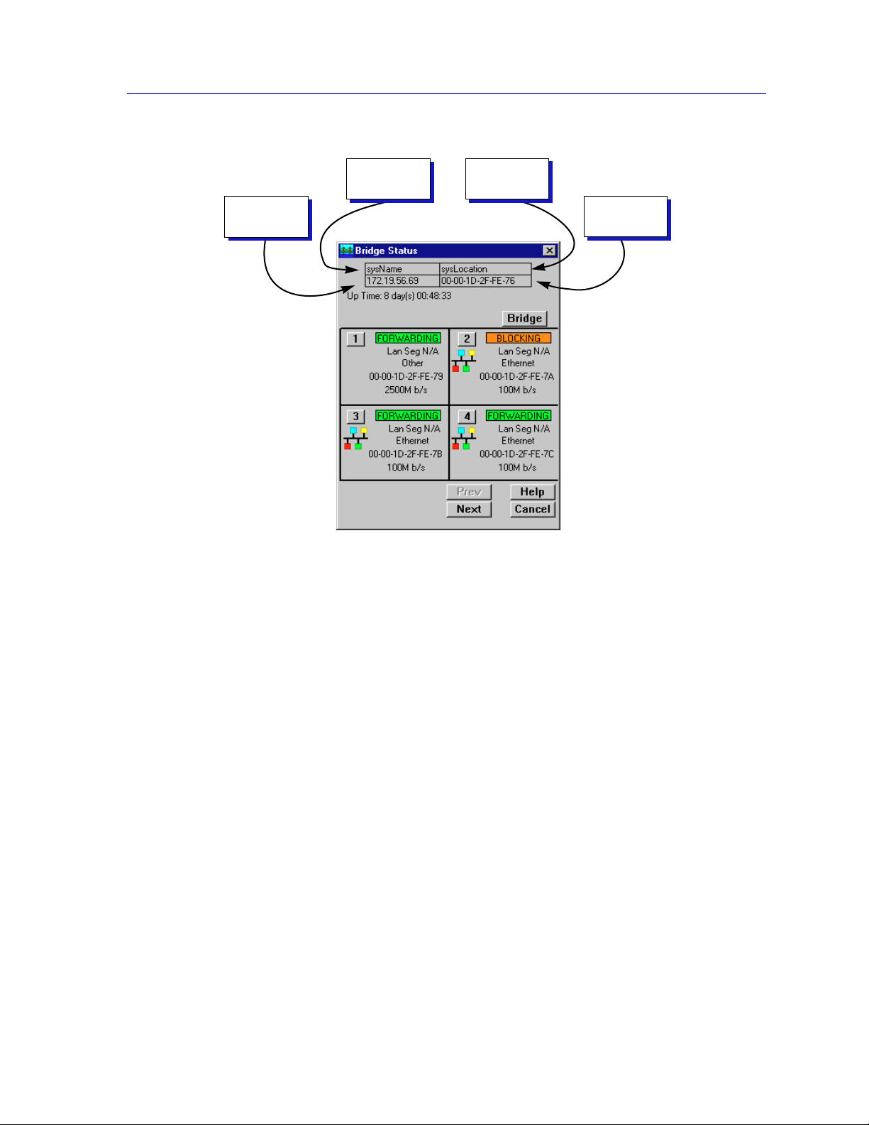
Device
Name
IP Address
Figure 1-1. Sample Window Showing Informational Text Boxes
Location
MAC
Address
Device Name
Displays the user-defined name of the device. The device name can be changed
via the System Group window; see the Generic SNMP Management Module
Guide for details.
IP Address
Displays the device’s IP (Internet Protocol) Address; this will be the IP address
used to define the device icon. The IP address is assigned via Local Management,
and cannot be changed via SPECTRUM Element Manager. Note that although
each interface on a 9H42x-xx module has its own MAC, or physical, address, only
a single IP address is assigned.
Location
Displays the user-defined location of the device. The location is entered through
the System Group window; see the Generic SNMP Guide for details.
MAC Address
Displays the manufacturer-set MAC address of the interface through which
SPECTRUM Element Manager is communicating with the 9H42x-xx module
(typically the SMB10 backplane management interface). MAC addresses are
factory-set and cannot be altered.
Software Conventions 1-5

Introduction
Using Buttons
The button that appears at the bottom of most windows allows you to
exit a window and terminate any unsaved changes you have made. You may also
have to use this button to close a window after you have made any necessary
changes and set them by clicking on an , , or button.
An , , or button appears in windows that have
configurable values; it allows you to confirm and SET changes you have made to
those values. In some windows, you may have to use this button to confirm each
individual set; in other windows, you can set several values at once and confirm
the sets with one click on the button.
The button brings up a Help text box with information specific to the
current window. For more information concerning Help buttons, see Getting
Help, page 1-6.
The command buttons (for example ) call up a menu listing the windows,
screens, or commands available for that topic.
Any menu topic followed by ... (three dots) — for example, Statistics... — calls up
a window or screen associated with that topic.
Getting Help
This section describes different methods of getting help for questions or concerns
you may have while using SPECTRUM Element Manager.
Using On-line Help
You can use the 9H42x-xx module window buttons to obtain information
specific to the device. When you click on a Help button, a window will appear
which contains context-sensitive on-screen documentation that will assist you in
the use of the windows and their associated command and menu options. Note
that if a Help button is grayed out, on-line help has not yet been implemented for
the associated window.
From the Help menu accessed from the Module View window menu bar, you can
access on-line Help specific to the Module View, as well as bring up the Chassis
Manager window for reference. Refer to Chapter 2 for information on the Module
View and Chassis Manager windows.
All of the SPECTRUM Element Manager help windows use the standard Microsoft
NOTE
Windows help facility; if you are unfamiliar with this feature of Windows, you can select
Help —>How to Use Help from the primary window menu bar, or consult your
Microsoft Windows User’s Guide.
1-6 Getting Help

Getting Help from Cabletron Systems’ Global Call Center
If you need support related to SPECTRUM Element Manager, or if you have any
questions, comments, or suggestions related to this manual or any of our
products, please feel free to contact Cabletron Systems’ Global Call Center via one
of the following methods:
By phone: Monday through Friday between 8 AM and 8 PM
Eastern Standard Time at (603) 332-9400
By mail: Cabletron Systems, Inc.
PO Box 5005
Rochester, NH 03866-5005
By Internet mail: support@ctron.com
By FTP ftp.ctron.com (134.141.197.25)
Login anonymous
Password your email address
By BBS: (603) 335-3358
Modem Setting 8N1: 8 data bits, 1 stop bit, No parity
Introduction
For additional information about Cabletron Systems products, visit our World
Wide Web site: http://www.cabletron.com/. For Technical Support, select Service
and Support.
9H42x-xx Firmware
SPECTRUM Element Manager support for the 9H42x-xx series of MMAC-Plus
SmartSwitches has been tested against the following firmware versions:
• 9H421-12: version 1.07.06
• 9H422-12: version 1.04.11
• 9H423-28: version 1.05.04
• 9H429-12: version 1.04.10
The 9H423-26 has not yet been customer-released; management support for this
device is beta quality.
As a general rule, firmware versions for new products are liable to change rapidly; contact
NOTE
Cabletron Systems’ Global Call Center, your local sales representative, or our Web site for
upgrade information for the latest customer release of firmware.
9H42x-xx Firmware 1-7

Introduction
1-8 9H42x-xx Firmware

Chapter 2
The 9H42x-xx Module View
Accessing the Module View; information displayed in the Module View window; the Chassis Manager
window; module management functions; port configuration
The Module View window is the main screen that immediately informs you of the
status of the front panel interfaces and the INB backplane connection on your
9H42x-xx module via a color-coded, graphical display. The Module View window
serves as a single point of access to all management functions available for an
individual 9H42x-xx module.
You can launch the 9H42x-xx module view directly from an individual device
icon, or from within an MMAC-Plus Chassis view:
TIP
from an individual device icon:
1. In any map, list, or tree vie w , doub le-click on the 9H42x-xx module y ou wish to
manage;
or
1. In any map, list, or tree view, click the left mouse button once to select the
module you wish to manage.
2. Select Manage—>Node from the primary window menu bar, or select the
Manage Node toolbar button.
or
1. In any map, list, or tree view, click the right mouse button once to select the
module you wish to manage.
2. On the resulting menu, click to select Manage.
To successfully launch the Module View in the above ways, you must have selected either
Chassis Manager or User Selectable as the default MMAC-Plus Startup Option. You
set these options via the Node page in the Tools—>Options window; see your
Installing and Using guide for more details.
2-1
The 9H42x-xx Module View
from the MMAC-Plus Chassis View:
1. Click the left mouse button on the index number for the slot which contains
the 9H42x-xx module you wish to manage.
2. On the resulting menu, click to select Device View .
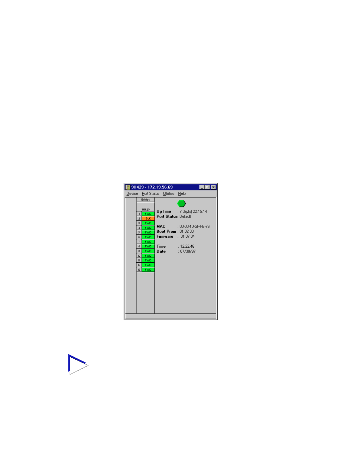
The 9H42x-xx Module View, illustrated in Figure 2-1, will appear.
Viewing Module Information
The Module View window (Figure 2-1) provides a graphic representation of the
9H42x-xx Module, including a color-coded port display which immediately
informs you of the current configuration and status of the module and its ports.
Note that the Module View display is essentially the same for all 9H42x-xx
modules; the only difference is the number of front panel interfaces.
Figure 2-1. 9H42x-xx Module View Window
For the 9H423-26 and 9H423-28 modules, the interface display will include arrows at the
TIP
2-2 Viewing Module Information
top and bottom; these allow you to shift the port display so that you can view the status of
and access management for all available ports.

By clicking in designated areas of the module’s graphical display (as detailed later
in this chapter), or by using the menu bar at the top of the Module View window,
you can access all of the menus that lead to more detailed device- and port- level
windows.
When you move the mouse cursor over a management “hot spot” the cursor icon will
TIP
change into a “hand” to indicate that clicking in the current location will bring up a
management option.
Front Panel Information
The areas above and to the right of the main module display area provide the
following device information:
IP
The Module View window title displays the device’s IP (Internet Protocol)
Address; this will be the IP address you have used to create the 9H42x-xx module
in the Chassis Setup window, or the IP address used to define the device icon. The
IP address is assigned via Local Management, and cannot be changed via
SPECTRUM Element Manager. Note that although each interface on the 9H42x-xx
module has its own MAC, or physical, address, only a single IP address is
assigned.
The 9H42x-xx Module View
Connection Status
This color-coded area indicates the current state of communication between
SPECTRUM Element Manager and the 9H42x-xx module:
• Green indicates the 9H42x-xx is responding to device polls (valid connection).
• Magenta indicates that the 9H42x-xx is in a temporary stand-by mode while it
responds to a physical change in the hub (such as when a board is inserted);
note that board and port menus are inactive during this stand-by state.
• Blue indicates an unknown contact status — polling has not yet been
established with the 9H42x-xx module.
• Red indicates the 9H42x-xx module is not responding to device polls (device
is off line, or device polling has failed across the network for some other
reason).
Up Time
The amount of time, in a day(s) hh:mm:ss format, that the 9H42x-xx Module has
been running since the last start-up.
Port Status
Indicates the Port Status display selection currently in effect. The default port
status view is bridge status; if you have not changed the port status selection since
launching the Module View window, this field will display Default. For more
information about changing the port status display, see page 2-8.
Viewing Module Information 2-3

The 9H42x-xx Module View
MAC
The physical layer address assigned to the interface through which SPECTRUM
Element Manager is communicating with the 9H42x-xx Module. Unless your
management station is communicating through the front panel of the module,
this will reflect the MAC address of the SMB 10 backplane management interface.
MAC addresses are hard-coded in the device, and are not configurable.
Boot Prom
The revision of BOOT PROM installed in the 9H42x-xx module.
Firmware
The revision of device firmware stored in the 9H42x-xx module’s FLASH PROMs.
Time
The current time, in a 24-hour hh:mm:ss format, set in the 9H42x-xx module’s
internal clock.
Date
The current date, in an mm/dd/yy format, set in the 9H42x-xx module’s internal
clock.
You can set the date and time by using the Edit Device Date and Edit Device Time
NOTE
options on the Device menu; see Setting the Device Date and Time, page 2-25, for
details.
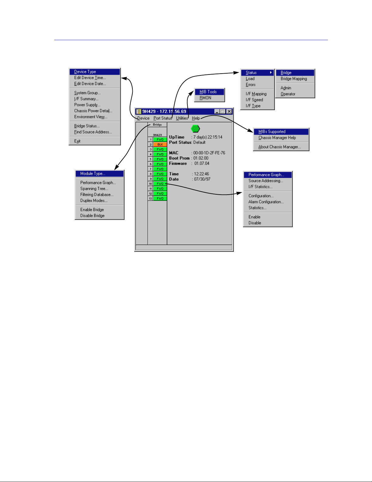
Menu Structure
By clicking on various areas of the Module View display, you can access menus
with bridging configuration and performance options, as well as utility
applications and general device management functions. The following illustration
displays the menu structure and indicates how to use the mouse to access the
various menus:
2-4 Viewing Module Information
The 9H42x-xx Module View
Figure 2-2. 9H42x-xx Module View Menu Structure
The Device Menu
From the Device Menu at the Module View window menu bar, you can access the
following selections:
• Device Type..., which displays a window containing a description of the
device being modeled.
• Edit Device Time... and Edit Device Date..., which allow you to set the
9H42x-xx module’s internal clock.
• System Group..., which allows you to manage the 9H42x-xx module via
SNMP MIB II. Refer to the Generic SNMP User’s Guide for further
information.
• I/F Summary, which lets you view statistics (displayed both graphically and
numerically) for the traffic processed by each network interface on your
device. See Viewing I/F Summary Information, page 2-13, for details.
Viewing Module Information 2-5

The 9H42x-xx Module View
• Power Supply, Chassis Power Detail, and Environment View provide access
to windows which provide information about the MMAC-Plus chassis the
selected module is installed in. A detailed description of these windows can be
found in the Using MMAC-Plus Remote Management User’s Guide included
with your software.
• Bridge Status..., which opens a window that provides an overview of bridging
information for each port, and allows you to access all other bridge-related
options. Refer to Chapter 5, Bridging, for more information.
• Find Source Address..., which opens a window that allows you to search the
9H42x-xx’s 802.1d Filtering Database to determine which switching interface
a specified source MAC address is communicating through. If the MAC
address is detected as communicating through the switch, the port display will
flash to indicate the switch interface of interest.
• Exit, which closes the 9H42x-xx Module View window.
The Port Status Menu
The Port Status menu allows you to select the status information that will be
displayed in the port text boxes in the Module View window:
• Status allows you to select one of four status type displays: Bridge, Bridge
Mapping, Admin, or Operator.
• Load will display the portion of network load processed per polling interval
by each interface, expressed as a percentage of the theoretical maximum load
(10 or 100 Mbits/sec).
• Errors allows you to display the number of errors detected per polling interval
by each interface, expressed as a percentage of the total number of valid
packets processed by the interface.
• I/F Port Mapping will display the interface (if) index associated with each port
on your 9H42x-xx module.
• I/F Speed will display the port’s bandwidth: 10 or 100 Mbits/sec. Note that the
module’s backplane INB interface has a bandwidth of 2500 Mbits/sec.
• I/F Type will display the interface type of each port on the 9H42x-xx module:
Eth (ethernet) for all front-panel interfaces, and Other for the backplane INB
interface.
For more information on the port display options available via this menu, see Port
Status Displays, page 2-8.
The Utilities Menu
The Utilities menu provides access to two important utilities provided by
SPECTRUM Element Manager for use with the 9H42x-xx modules: the MIB Tools
utility, which provides direct access to the 9H42x-xx module’s MIB information;
and the RMON utility, a remote monitoring utility which is implemented by
many of Cabletron Systems’ intelligent devices. These selections are also available
from the Tools menu in the primary window menu bar.
2-6 Viewing Module Information

The 9H42x-xx Module View
Refer to your SPECTRUM Element Manager Tools Guide for information on the
MIB Tools utility, and to the SPECTRUM Element Manager Remote Monitoring
(RMON) User’s Guide for more information on the RMON tool.
The Help Menu
The Help Menu has three selections:
• MIBS Supported, which brings up the Chassis Manager window, described
on page 2-11.
• Chassis Manager Help, which brings up a help window with information
specifically related to using the Chassis Manager and Module View windows.
• About Chassis Manager..., which brings up a version window for the Chassis
Manager application in use.
The Bridge Menu
The Bridge menu is available by clicking on the Bridge label above the port
display; it offers access to the following bridge-specific options, which are
discussed in detail in Chapter 5, Bridging:
• Module Type..., which displays a window containing a description of the
device being modeled; this is the same information displayed in the Device
Type window available from the Device menu. See Viewing the Device Type,
page 2-12.
• Performance Graph..., which visually displays the combined performance of
all bridging interfaces on the selected module; see Chapter 5, Bridging.
• Spanning Tree..., which allows you to set bridge parameters related to the
Spanning Tree Algorithm (STA) – the method that bridges use to decide the
controlling (root) bridge when two or more bridges are in parallel. See Chapter
5, Bridging, for more information.
• Filtering Database..., which displays a window to configure the bridge’s
acquired and permanent filtering databases used to filter or forward traffic
across the 9H42x-xx module.
• Duplex Modes..., which allows you to set the Duplex Mode for each interface
on the module.
• Disable/Enable Bridge, which enables or disables bridging across every
interface on the module.
Viewing Module Information 2-7

The 9H42x-xx Module View
The Port Menu
The menu for the INB and Ethernet interfaces offers the following selections:
• Performance Graph..., which brings up a bridging statistics window specific
to the selected interface.
• Source Addressing...., which brings up a window allowing you to see which
source addresses are communicating through the selected switch port when it
is using 802.1d bridging. See Using Source Addressing in Chapter 5 for more
information.
• I/F Statistics..., which provides direct access to MIB-II interface statistics for
the selected interface. Note that this window may also appear in response to
the Statistics selection described below, if the RMON MIB component has
been disabled for the selected module. See Chapter 4, Statistics, for more
information.
• Configuration..., which allows you to set the duplex mode for standard
Ethernet and 100Base-FX fiber interfaces, or configure auto-negotiation
parameters for any 100Base-TX interfaces. See Configuring Ports, page 2-19,
for more information; note that this option is not available for the INB
backplane interface.
• Alarm Configuration..., which brings up windows that allow you to configure
RMON-based alarms and events for each interface; see Chapter 3, Alarm
Configuration, for details.
• Statistics..., which launches the highest level of statistics currently available
for the selected interfaces. For all front panel interfaces (both standard
Ethernet and Fast Ethernet), RMON statistics will be displayed if the RMON
Default MIB component is active; if it has been disabled, MIB-II interface
statistics will display. See Chapter 4, Statistics, for more information.
• Enable and Disable, which let you enable or disable bridging across the
selected interface; see Enabling and Disabling Ports, page 2-26.
Port Status Displays
When you open the Module View window, each port will display its current
bridging state (defined below); to change this status display, select one of the
options on the Port Status menu, as described in the following sections.
For all 9H42x-xx modules, the port text box indexed “1” indicates the fixed interface to
TIP
the INB-2 backplane bus; interfaces indexed “2” through “xx” indicate the front panel
switching interfaces.
2-8 Viewing Module Information

Selecting a Port Status View
To change the status view of your ports:
1. Click on Port Status on the menu bar at the top of the Module Vie w window; a
menu will appear.
2. Drag down (and to the right, if necessary) to select the status information you
want to display. The port text boxes will display the appropriate status
information.
Port status view options are:
Status
You can view four port status categories, as follows:
• Bridge — FWD, DIS, LRN, LIS, BLK, or BRK
• Bridge Mapping
• Admin — ON or OFF
• Operator — ON or OFF
If you have selected the Bridge status mode, a port is considered:
The 9H42x-xx Module View
• FWD (Forwarding) if the port is on-line and ready to forward packets across
the 9H42x-xx from one network segment to another. Note that this is also the
default display for ports which are administratively enabled but not
connected.
• DIS (Disabled) if bridging at the port has been disabled by management; no
traffic can be received or forwarded on this port, including configuration
information for the bridged topology.
• LIS (Listening) if the port is not adding information to the filtering database. It
is monitoring Bridge Protocol Data Unit (BPDU) traffic while preparing to
move to the forwarding state.
• LRN (Learning) if the Forwarding database is being created, or the Spanning
Tree Algorithm is being executed because of a network topology change. The
port is monitoring network traffic, and learning network addresses.
• BLK (Blocking) if the port is on-line, but filtering traffic from going across the
9H42x-xx from one network segment to another. Bridge topology information
will be forwarded by the port.
• BRK (Broken) if the physical interface has malfunctioned.
If you have selected Bridge Mapping, the port status boxes will display the bridge
interface index numbers assigned to each interface (which may or may not match
the ifIndex values displayed via the I/F Mapping option described below).
Viewing Module Information 2-9

The 9H42x-xx Module View
If you have selected the Admin status mode, a port is considered:
• ON if the port is enabled by management.
• OFF if it has been disabled through management action.
Note that the Admin state reflects the state requested by management; depending
on the circumstances, this may or may not match the current Operator status,
described below.
If you have selected the Operator status mode, a port is considered:
• ON if the port is currently forwarding packets.
• OFF if the port is not currently forwarding packets.
Note that the Operator status provides the actual status of the port; depending on
the circumstances, this may or may not reflect the Admin state currently requested
by management. For example, ports which are administratively ON but not yet
connected would display an Operator status of OFF, since no packets are being
forwarded.
NOTE
Load
If you choose Load, the interface text boxes will display the percentage of
network load processed by each port during the last polling interval. This
percentage reflects the network load generated per polling interval by devices
connected to the port compared to the theoretical maximum load (10 or 100
Mbits/sec) of the connected network.
Errors
If you choose the Errors mode, the interface boxes will display the percentage of
the total number of valid packets processed by each port during the last polling
interval that were error packets. This percentage reflects the number of errors
generated during the last polling interval by devices connected to that port
compared to the total number of valid packets processed by the port.
In SPECTRUM Element Manager, the polling interval is set using the
Tools—>Options window available from the primary window menu bar, or via the
individual device icon’s Properties window. Refer to the Installing and Using
SPECTRUM Element Manager guide for full information on setting device polling
intervals.
I/F Mapping
If you choose the I/F Mapping mode, the interface boxes will display the interface
number (IfIndex) associated with each port on the 9H42x-xx module. Note that
this value may or may not correspond to the bridge port index displayed via the
Bridge Mapping option (described above).
2-10 Viewing Module Information

I/F Speed
If you choose the I/F Speed mode, the interface boxes will display the bandwidth
of each individual interface on the 9H42x-xx module: 10M (megabits) for
standard Ethernet; 100M for Fast Ethernet; and 2500M for the INB backplane
interface.
I/F Type
If you choose the I/F Type mode, the interface boxes will display the network
type supported by each interface on the 9H42x-xx module: Eth (ethernet-csmacd)
or Other (for the INB backplane interface). Note that there is no type distinction
between standard Ethernet and Fast Ethernet.
Port Status Color Codes
Three of the Port Status display options — Bridge, Admin, and Operator —
incorporate their own color coding schemes: for the Bridge option, green = FWD,
blue = DIS, magenta = LIS or LRN, orange = BLK, and red = BRK; for Admin and
Operator, green = ON, red = OFF, and blue = N/A (not available).
For all other Port Status selections — Bridge Mapping, Load, Errors, I/F
Mapping, I/F Speed, and I/F Type — color codes will continue to reflect the most
recently-selected mode which incorporates its own color coding scheme.
The 9H42x-xx Module View
The Chassis Manager Window
Like most networking devices, Cabletron’s devices draw their functionality from
a collection of proprietary MIBs and IETF RFCs. In addition, Cabletron’s newer
intelligent devices — like the 9H42x-xx module — organize their MIB data into a
series of “components.” A MIB component is a logical grouping of MIB data, and
each group controls a defined set of objects. For example, 9H42x-xx bridging
information is organized into its own component; more generic device and port
information resides in the chassis component. Note, too, that there is no
one-to-one correspondence between MIBs and MIB components; a single MIB
component might contain objects from several different proprietary MIBs and
RFCs.
The Chassis Manager window, Figure 2-3, is a read-only window that displays
the MIBs and the MIB components — and, therefore, the functionality —
supported by the currently monitored device.
Viewing Module Information 2-11

The 9H42x-xx Module View
The MIBs which provide the
9H42x-xx module’s functionality
— both proprietary MIBs and
IETF RFCs — are listed here
MIB Components are listed here;
remember, there’s no one-to-one
correspondence between MIBs
and MIB Components
To view the Chassis Manager window:
1. Click on Help on the menu bar at the top of the Module View window.
2. Click again to select MIBs Supported, and release.
Figure 2-3. Chassis Manager Window
Viewing the Device Type
In addition to the graphical displays described above, the Device Type option on
the Device menu and the Module Type option on the Bridge menu bring up
windows that list the physical characteristics of the 9H42x-xx module and its
ports:
Figure 2-4. Sample Device Type Windows
2-12 Viewing Module Information
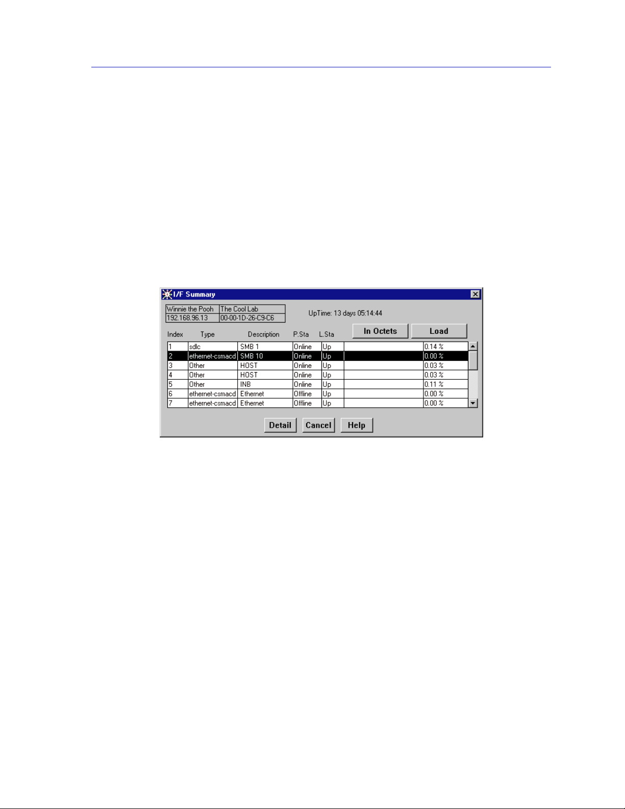
Viewing I/F Summary Information
The I/F Summary menu option available from the Device menu lets you view
statistics (displayed both graphically and numerically) for the traffic processed by
each network interface on your device. The window also provides access to a
detailed statistics window that breaks down Transmit and Receive traffic for each
interface; in addition, an Applications button in the I/F Summary window lets
you access SNMP MIB-II windows for device management.
To access the I/F Summary window:
1. From the Module View, click on the Device option from the menu bar.
2. Click again to select I/F Summary, and release. The I/F Summary window,
Figure 2-5, will appear.
The 9H42x-xx Module View
Figure 2-5. I/F Summary Window
The I/F Summary window provides a variety of descriptive information about
each interface on your device, as well as a bar graph and statistics which display
each interface’s performance.
The following descriptive information is provided for each interface:
UpTime
The UpTime field lists the amount of time, in a days, hh:mm:ss format, that the
device has been running since the last start-up
Index
The index value assigned to each interface on the device.
Type
The type of the interface, distinguished by the physical/link protocol(s) running
immediately below the network layer. Possible values are sdlc (for the backplane
SMB 1 management interface), Other (for the 9H42x-xx module’s two internal
Viewing Module Information 2-13
 Loading...