

Cabletron Systems MMAC-Plus 9H531-18, 9H531-17, 9H531-24, MMAC-Plus 9H532-17, 9H532-24 User Manual
...Page 1

9033130-05
SmartSwitch 9000
9X5XX-Series Local Management
User’s Guide
Page 2

Page 3

i
Notice
NOTICE
Cabletron Systems reserves the right to make changes in specifications and other information
contained in this document without prior notice. The reader should in all cases consult Cabletron
Systems to determine whether any such changes have been made.
The hardware, firmware, or software described in this manual is subject to change without notice.
IN NO EVENT SHALL CABLETRON SYSTEMS BE LIABLE FOR ANY INCIDENTAL, INDIRECT,
SPECIAL, OR CONSEQUENTIAL DAMAGES WHATSOEVER (INCLUDING BUT NOT LIMITED
TO LOST PROFITS) ARISING OUT OF OR RELATED TO THIS MANUAL OR THE INFORMATION
CONTAINED IN IT, EVEN IF CABLETRON SYSTEMS HAS BEEN ADVISED OF, KNOWN, OR
SHOULD HAVE KNOWN, THE POSSIBILITY OF SUCH DAMAGES.
Cabletron Systems, Inc.
35 Industrial Way
Rochester, NH 03867
© February 2000 Cabletron Systems, Inc.:
All Rights Reserved
Printed in the United States of America
Order Number: 9033130-05
SmartSwitch is a trademark of Cabletron Systems, Inc.
i960 microprocessor is a registered trademark of Intel Corp.
Ethernet is a trademark of Xerox Corporation.
Page 4

ii
Notice
FCC NOTICE
This device complies with Part 15 of the FCC rules. Operation is subject to the following two
conditions: (1) this device may not cause harmful interference, and (2) this device must accept any
interference received, including interference that may cause undesired operation.
NOTE: This equipment has been tested and found to comply w ith the limits for a Class A digital
device, pursuant to Part 15 of the FCC rules. These limits are designed to provide reasonable
protection against harmful interference when the equipment is operated in a commercial environment.
This equipment uses, generates, and can radiate radio frequency energy and if not installed in
accordance with the operator’s manual, may cause harmful interference to radio communications.
Operation of this equipment in a residential area is likely to cause interference in which case the user
will be required to correct the interference at his own expense.
WARNING: Changes or modifications made to this device which are not expressly approved by the
party responsible for compliance could void the user’s authority to operate the equipment.
INDUSTRY CANADA NOTICE
This digital apparatus does not exceed the Class A limits for radio noise emiss ions from digital
apparatus set out in the Radio Interference Regulations of the Canadian Department of
Communications.
Le présent appareil numérique n’émet pas de bruits radioélectriques dépassant les limites applicables
aux appareils numériques de la class A prescrites dans le Règlement sur le brouillage radi oélectrique
édicté par le ministère des Communications du Canada.
NOTICE: The Industry Canada label identifies certified equipment. This certification means that the
equipment meets telecommunications network protective, operational and safety requirements as
prescribed in the appropriate Terminal Equipment Technical Requirements documents (s). The
department does not guarantee the equipment will operate to the user’s satisfacti on .
Before installing this equipment, users should ensure that it is permissible to be conn ected to the
facilities of the local telecommunications company. The equipment must also be installed using an
acceptable method of connection. The customer should be aware that compliance with the above
conditions may not prevent degradation of service in some situations.
Repairs to certified equipment should be coordinated by a representative designated by the supplier.
Any repairs or alterations made by the user to this equipmen t, or equipment malfunctions, may give
the telecommunications company cause to request the us er to disco nn e ct the equipment.
Users should ensure for their own protection that the electrical ground connections of the power
utility, telephone lines and internal metallic water pipe system, if present, are connected together. This
precaution may be particularly important in rural areas. Caution: Users should not attempt to make
such connections themselves, but should contact the appropriate electric inspection authority, or
electrician, as appropriate.
NOTICE: The Ringer Equivalence Number (REN) assigned to each terminal device provides an
indication of the maximum number of terminals allowed to be c onnected to a telephone interface. The
termination on an interface may consist of any combination of devices subject only to the requirement
that the sum of the ringer equivalence Numbers of all the devices does not exceed 5.
Page 5

iii
Notice
VCCI NOTICE
This is a Class A product based on the standard of the Voluntary Control Council for Interference by Information Technology
Equipment (VCCI). If this equipment is used in a domestic environment, radio disturbance may arise. When such trouble
occurs, the user may be required to take corrective actions.
CABLETRON SYSTEMS, INC.
PROGRAM LICENSE AGREEMENT
IMPORTANT:THIS LICENSE APPLIES FOR USE OF PRODUCT IN THE FOLLOWING GEOGRAPHICAL
REGIONS:
CANADA
MEXICO
CENTRAL AMERICA
SOUTH AMERICA
BEFORE OPENING OR UTILIZING THE ENCLOSED PRODUCT, CAREFULLY READ THIS
LICENSE AGREEMENT.
This document is an agreement (“Agreem ent”) between You, the end user , and Cabletr on Systems, Inc.
(“Cabletron”) that sets forth your rights and obligations with respect to the Cabletron software
program (“Program”) in the package. The Program may be contained in firmware, chips or other
media. UTILIZING THE ENCLOSED PRODUCT, YOU ARE AGREEING TO BECOME BOUND BY
THE TERMS OF THIS AGREEMENT, WHICH INCLUDES THE LICENSE AND THE LIMITATION
OF WARRANTY AND DISCLAIMER OF LIABILITY. IF YOU DO NOT AGREE TO THE TERMS OF
THIS AGREEMENT, RETURN THE UNOPENED PRODUCT TO CABLETRON OR YOUR DEALER,
IF ANY, WITHIN TEN (10) DAYS FOLLOWING THE DATE OF RECEIPT FOR A FULL REFUND.
IF YOU HAVE ANY QUESTIONS ABOUT THIS AGREEMENT, CONTACT CABLETRON SYSTEMS
+1- 603-332-9400. Attn: Legal Department.
1. LICENSE. You have the right to use only the one (1) copy of the Program provided in th is package
subject to the terms and conditions of this License Agreement.
You may not copy, reproduce or transmit any part of the Program except as permitted by the
Copyright Act of the United States or as authorized in writing by Cabletron.
2. OTHER RESTRICTIONS. You may not reverse engineer, decompile, or disassemble the
Program.
Page 6

Notice
iv
3. APPLICABLE LAW. This License Agreement shall be interpreted and governed under the laws
and in the state and federal courts of New Ham pshire. You accept th e perso nal jurisdictio n an d ven ue
of the New Hampshire courts.
4. EXPORT REQUIREMENTS. You understand that Cabletron and its Affiliates are subject to
regulation by agencies of the U.S. Government, including the U.S. Department of Commerce, which
prohibit export or diversion of certain technical products to certain countries, unless a license to export
the product is o btai ned from the U .S. G overnme nt or an e xc eptio n f rom ob tain ing such lic ense may b e
relied upon by the exporting party.
If the Program is exported from the United States pursuant to the License Exception CIV under the
U.S. Export Administration Regulations, You agree that You are a civil end user of the Program and
agree that You will use the Program for civil end uses only and not for military purposes.
If the Program is exported from the United States pursuant to the License Exception TSR under the
U.S. Export Administration Regulations, in addition to the restriction on transfer set forth in Sections 1
or 2 of this Agreement, You agree not to (i) reexport or release the Program, the source code for the
Program or technology to a national of a coun try in Country Groups D:1 or E:2 (Albania, Armenia,
Azerbaijan, Belarus, Bulgaria, Cambodia, Cuba, Estonia, Geor gia, Iraq, Kaz akhstan, Kyr gyzstan, Laos,
Latvia, Libya, Lithuania, Moldova, North Korea, the People’s Republic of China, Romania, Russia,
Rwanda, Tajikistan, Turkmenistan, Ukraine, Uzbekistan, Vietnam, or such other countries as may be
designated by the United States Government), (ii) export to Country Groups D:1 or E:2 (as defined
herein) the direct product of the Pr og ram or the techno logy, if such foreign produced direct product is
subject to national security controls as identified on the U.S. Commerce Control List, or (iii) if the
direct product of the technology is a complete plant o r any major component of a plant, export to
Country Groups D:1 or E:2 the direct product of the plant or a major component thereof, if such
foreign produced direct product is subject to national security controls as identified on the U.S.
Commerce Control List or is subject to State Department controls under the U.S. Munitions List.
5. UNITED STATES GOVERNMENT RESTRICTED RIGHTS. The enclosed Product (i) was
developed solely at private expense; (ii) contains “restricted computer software” submitted with
restricted rights in accordance with section 52.227-19 (a) through (d) of the Commercial Computer
Software-Restricted Rights Clause and its successors, and (iii) in all respects is proprietary data
belonging to Cabletron and/or its suppliers. For Department of Defense units, the Product is
considered commercial computer software in accordance with DFARS section 227.7202-3 and its
successors, and use, duplication, or disclosure by the Government is subject to restrictions set forth
herein.
6. EXCLUSION OF WARRANTY. Except as may be specifically provided by Cabletron in writing,
Cabletron makes no warranty, expressed or implied, concerning the Program (including its
documentation and media).
CABLETRON DISCLAIMS ALL WARRANTIES, OTHER THAN THOSE SUPPLIED TO YOU BY
CABLETRON IN WRITING, EITHER EXPRESS OR IMPLIED, INCLUDING BUT NOT LIMITED TO
IMPLIED WARRANTIES OF MERCHANTABILITY AND FITNESS FOR A PARTICULAR PURPOSE,
WITH RESPECT TO THE PROGRAM, THE ACCOMPANYING WRITTEN MATERIALS, AND ANY
ACCOMPANYING HARDWARE.
Page 7

v
Notice
7. NO LIABILITY FOR CONSEQUENTIAL DAMAGES. IN NO EVENT SHALL CABLETRON OR
ITS SUPPLIERS BE LIABLE FOR ANY DAMAGES WHATSOEVER (INCLUDING, WITHOUT
LIMITATION, DAMAGES FOR LOSS OF BUSINESS, PROFITS, BUSINESS INTERRUPTION, LOSS
OF BUSINESS INFORMATION, SPECIAL, INCIDENTAL, CONSEQUENTIAL, OR RELIANCE
DAMAGES, OR OTHER LOSS) ARISING OUT OF THE USE OR INABILITY TO USE THIS
CABLETRON PRODUCT, EVEN IF CABLETRON HAS BEEN ADVISED OF THE POSSIBILITY OF
SUCH DAMAGES. BECAUSE SOME STATES DO NOT ALLOW THE EXCLU SION OR LIMITATION
OF LIABILITY FOR CONSEQUENTIAL OR INCIDENTAL DAMAGES, OR IN THE DURATION OR
LIMITATION OF IMPLIED WARRANTIES IN SOME INSTANCES, THE ABOVE LIMITATION AND
EXCLUSIONS MAY NOT APPLY TO YOU.
Page 8

Notice
vi
CABLETRON SYSTEMS SALES AND SERVICE, INC.
PROGRAM LICENSE AGREEMENT
IMPORTANT: THIS LICENSE APPLIES FOR USE OF PRODUCT IN THE UNITED STATES OF AMERICA
AND BY UNITED STATES OF AMERICA GOVERNMENT END USERS.
BEFORE OPENING OR UTILIZING THE ENCLOSED PRODUCT, CAREFULLY READ THIS
LICENSE AGREEMENT.
This document is an agreement (“Agreement”) between You, the end user, and Cabletron Systems
Sales and Service, Inc. (“Cabletron”) that sets forth your rights and obligations with respect to the
Cabletron software program (“Pr ogram”) in the package. The Pr ogram may be contained in firmwar e,
chips or other media. UTILIZING THE ENCLOSED PRODUCT, YOU ARE AGREEING TO BECOME
BOUND BY THE TERMS OF THIS AGREEMENT, WHICH INCLUDES THE LICENSE AND THE
LIMITATION OF WARRANTY AND DISCLAIMER OF LIABILITY. IF YOU DO NOT AGREE TO
THE TERMS OF THIS AGREEMENT, RETURN THE UNOPENED PRODUCT TO CABLETRON OR
YOUR DEALER, IF ANY, WITHIN TEN (10) DAYS FOLLOWING THE DATE OF RECEIPT FOR A
FULL REFUND.
IF YOU HAVE ANY QUESTIONS ABOUT THIS AGREEMENT, CONTACT CABLETRON SYSTEMS
+1-603-332-9400. Attn: Legal Department.
1. LICENSE. You have the right to use only the one (1) copy of the Program provided in this package
subject to the terms and conditions of this License Agreement.
You may not copy, reproduce or transmit any part of the Program except as permitted by the
Copyright Act of the United States or as authorized in writing by Cabletron.
2. OTHER RESTRICTIONS. You may not reverse engineer, decompile, or disassemble the Program.
3. APPLICABLE LAW. This License Agreement shall be interpreted and governed under the laws
and in the state and federal courts of New Ham pshire. You accept th e personal jurisdiction and ven ue
of the New Hampshire courts.
4. EXPORT REQUIREMENTS. You understand that Cabletron and its Affiliates are subject to
regulation by agencies of the U.S. Government, including the U.S. Department of Commerce, which
prohibit export or diversion of certain technical products to certain countries, unless a license to export
the product is o btai ned from the U .S. G overnme nt or an e xc eptio n f rom ob tain ing such lic ense may b e
relied upon by the exporting party.
If the Program is exported from the United States pursuant to the License Exception CIV under the
U.S. Export Administration Regulations, You agree that You are a civil end user of the Program and
agree that You will use the Program for civil end uses only and not for military purposes.
If the Program is exported from the United States pursuant to the License Exception TSR under the
U.S. Export Administration Regulations, in addition to the restriction on transfer set forth in Sections 1
or 2 of this Agreement, You agree not to (i) reexport or release the Program, the source code for the
Program or technology to a national of a coun try in Country Groups D:1 or E:2 (Albania, Armenia,
Azerbaijan, Belarus, Bulgaria, Cambodia, Cuba, Estonia, Geor gia, Iraq, Kaz akhstan, Kyr gyzstan, Laos,
Latvia, Libya, Lithuania, Moldova, North Korea, the People’s Republic of China, Romania, Russia,
Rwanda, Tajikistan, Turkmenistan, Ukraine, Uzbekistan, Vietnam, or such other countries as may be
designated by the United States Government), (ii) export to Country Groups D:1 or E:2 (as defined
herein) the direct product of the Pr og ram or the techno logy, if such foreign produced direct product is
Page 9

vii
Notice
subject to national security controls as identified on the U.S. Commerce Control List, or (iii) if the
direct product of the technology is a complete plant o r any major component of a plant, export to
Country Groups D:1 or E:2 the direct product of the plant or a major component thereof, if such
foreign produced direct product is subject to national security controls as identified on the U.S.
Commerce Control List or is subject to State Department controls under the U.S. Munitions List.
5. UNITED STATES GOVERNMENT RESTRICTED RIGHTS. The enclosed Product (i) was
developed solely at private expense; (ii) contains “restricted computer software” submitted with
restricted rights in accordance with section 52.227-19 (a) through (d) of the Commercial Computer
Software-Restricted Rights Clause and its successors, and (iii) in all respects is proprietary data
belonging to Cabletron and/or its suppliers. For Department of Defense units, the Product is
considered commercial computer software in accordance with DFARS section 227.7202-3 and its
successors, and use, duplication, or disclosure by the Government is subject to restrictions set forth
herein.
6. EXCLUSION OF WARRANTY. Except as may be specifically provided by Cabletron in writing,
Cabletron makes no warranty, expressed or implied, concerning the Program (including its
documentation and media).
CABLETRON DISCLAIMS ALL WARRANTIES, OTHER THAN THOSE SUPPLIED TO YOU BY
CABLETRON IN WRITING, EITHER EXPRESS OR IMPLIED, INCLUDING BUT NOT LIMITED TO
IMPLIED WARRANTIES OF MERCHANTABILITY AND FITNESS FOR A PARTICULAR PURPOSE,
WITH RESPECT TO THE PROGRAM, THE ACCOMPANYING WRITTEN MATERIALS, AND ANY
ACCOMPANYING HARDWARE.
7. NO LIABILITY FOR CONSEQUENTIAL DAMAGES. IN NO EVENT SHALL CABLETRON OR
ITS SUPPLIERS BE LIABLE FOR ANY DAMAGES WHATSOEVER (INCLUDING, WITHOUT
LIMITATION, DAMAGES FOR LOSS OF BUSINESS, PROFITS, BUSINESS INTERRUPTION, LOSS
OF BUSINESS INFORMATION, SPECIAL, INCIDENTAL, CONSEQUENTIAL, OR RELIANCE
DAMAGES, OR OTHER LOSS) ARISING OUT OF THE USE OR INABILITY TO USE THIS
CABLETRON PRODUCT, EVEN IF CABLETRON HAS BEEN ADVISED OF THE POSSIBILITY OF
SUCH DAMAGES. BECAUSE SOME STATES DO NOT ALLOW THE EXCLU SION OR LIMITATION
OF LIABILITY FOR CONSEQUENTIAL OR INCIDENTAL DAMAGES, OR IN THE DURATION OR
LIMITATION OF IMPLIED WARRANTIES IN SOME INSTANCES, THE ABOVE LIMITATION AND
EXCLUSIONS MAY NOT APPLY TO YOU.
Page 10

Notice
viii
CABLETRON SYSTEMS LIMITED
PROGRAM LICENSE AGREEMENT
IMPORTANT: THIS LICENSE APPLIES FOR THE USE OF THE PRODUCT IN THE FOLLOWING
GEOGRAPHICAL REGIONS:
EUROPE
MIDDLE EAST
AFRICA
ASIA
AUSTRALIA
PACIFIC RIM
BEFORE OPENING OR UTILIZING THE ENCLOSED PRODUCT, CAREFULLY READ THIS
LICENSE AGREEMENT.
This document is an agreement (“Agreement”) between You, the end user, and Cabletron Systems
Limited (“Cabletron”) that sets forth your rights and obligations with respect to the Cabletron
software program (“Program”) in the package. The Program may be contained in firmware, chips or
other media. UTILIZING THE ENCLOSED PRODUCT, YOU ARE AGREEING TO BECOME BOUND
BY THE TERMS OF THIS AGREEMENT, WHIC H INCLUDES THE LICENSE AND THE
LIMITATION OF WARRANTY AND DISCLAIMER OF LIABILITY. IF YOU DO NOT AGREE TO
THE TERMS OF THIS AGREEMENT, RETURN THE UNOPENED PRODUCT TO CABLETRON OR
YOUR DEALER, IF ANY, WITHIN TEN (10) DAYS FOLLOWING THE DATE OF RECEIPT FOR A
FULL REFUND.
IF YOU HAVE ANY QUESTIONS ABOUT THIS AGREEMENT, CONTACT CABLETRON SYSTEMS
+1-603-332-9400. Attn: Legal Department.
1. LICENSE. You have the right to use only the one (1) copy of the Program provided in th is package
subject to the terms and conditions of this License Agreement.
You may not copy, reproduce or transmit any part of the Program except as permitted by the
Copyright Act of the United States or as authorized in writing by Cabletron.
2. OTHER RESTRICTIONS. You may not reverse engineer, decompile, or disassemble the
Program.
3. APPLICABLE LAW. This License Agreement s hall be governed in accordance with English law.
The English courts shall have exclusive jurisdiction in the event of any disputes.
4. EXPORT REQUIREMENTS. You understand that Cabletron and its Affiliates are subject to
regulation by agencies of the U.S. Government, including the U.S. Department of Commerce, which
prohibit export or diversion of certain technical products to certain countries, unless a license to export
the product is o btai ned from the U .S. G overnme nt or an e xc eptio n f rom ob tain ing such lic ense may b e
relied upon by the exporting party.
If the Program is exported from the United States pursuant to the License Exception CIV under the
U.S. Export Administration Regulations, You agree that You are a civil end user of the Program and
agree that You will use the Program for civil end uses only and not for military purposes.
If the Program is exported from the United States pursuant to the License Exception TSR under the
U.S. Export Administration Regulations, in addition to the restriction on transfer set forth in Sections 1
or 2 of this Agreement, You agree not to (i) reexport or release the Program, the source code for the
Program or technology to a national of a coun try in Country Groups D:1 or E:2 (Albania, Armenia,
Page 11

ix
Notice
Azerbaijan, Belarus, Bulgaria, Cambodia, Cuba, Estonia, Geor gia, Iraq, Kaz akhstan, Kyr gyzstan, Laos,
Latvia, Libya, Lithuania, Moldova, North Korea, the People’s Republic of China, Romania, Russia,
Rwanda, Tajikistan, Turkmenistan, Ukraine, Uzbekistan, Vietnam, or such other countries as may be
designated by the United States Government), (ii) export to Country Groups D:1 or E:2 (as defined
herein) the direct product of the Pr og ram or the techno logy, if such foreign produced direct product is
subject to national security controls as identified on the U.S. Commerce Control List, or (iii) if the
direct product of the technology is a complete plant o r any major component of a plant, export to
Country Groups D:1 or E:2 the direct product of the plant or a major component thereof, if such
foreign produced direct product is subject to national security controls as identified on the U.S.
Commerce Control List or is subject to State Department controls under the U.S. Munitions List.
5. UNITED STATES GOVERNMENT RESTRICTED RIGHTS. The enclosed Product (i) was
developed solely at private expense; (ii) contains “restricted computer software” submitted with
restricted rights in accordance with section 52.227-19 (a) through (d) of the Commercial Computer
Software-Restricted Rights Clause and its successors, and (iii) in all respects is proprietary data
belonging to Cabletron and/or its suppliers. For Department of Defense units, the Product is
considered commercial computer software in accordance with DFARS section 227.7202-3 and its
successors, and use, duplication, or disclosure by the Government is subject to restrictions set forth
herein.
6. EXCLUSION OF WARRANTY. Except as may be specifically provided by Cabletron in writing,
Cabletron makes no warranty, expressed or implied, concerning the Program (including its
documentation and media).
CABLETRON DISCLAIMS ALL WARRANTIES, OTHER THAN THOSE SUPPLIED TO YOU BY
CABLETRON IN WRITING, EITHER EXPRESS OR IMPLIED, INCLUDING BUT NOT LIMITED TO
IMPLIED WARRANTIES OF MERCHANTABILITY AND FITNESS FOR A PARTICULAR PURPOSE,
WITH RESPECT TO THE PROGRAM, THE ACCOMPANYING WRITTEN MATERIALS, AND ANY
ACCOMPANYING HARDWARE.
7. NO LIABILITY FOR CONSEQUENTIAL DAMAGES. IN NO EVENT SHALL CABLETRON OR
ITS SUPPLIERS BE LIABLE FOR ANY DAMAGES WHATSOEVER (INCLUDING, WITHOUT
LIMITATION, DAMAGES FOR LOSS OF BUSINESS, PROFITS, BUSINESS INTERRUPTION, LOSS
OF BUSINESS INFORMATION, SPECIAL, INCIDENTAL, CONSEQUENTIAL, OR RELIANCE
DAMAGES, OR OTHER LOSS) ARISING OUT OF THE USE OR INABILITY TO USE THIS
CABLETRON PRODUCT, EVEN IF CABLETRON HAS BEEN ADVISED OF THE POSSIBILITY OF
SUCH DAMAGES. BECAUSE SOME STATES DO NOT ALLOW THE EXCLU SION OR LIMITATION
OF LIABILITY FOR CONSEQUENTIAL OR INCIDENTAL DAMAGES, OR IN THE DURATION OR
LIMITATION OF IMPLIED WARRANTIES IN SOME INSTANCES, THE ABOVE LIMITATION AND
EXCLUSIONS MAY NOT APPLY TO YOU.
Page 12

Notice
x
DECLARATION OF CONFORMITY
Application of Council Directive(s): 89/336/EEC
73/23/EEC
Manufacturer’s Name: Cabletron Systems, Inc.
Manufacturer’s Address: 35 Industrial Way
PO Box 5005
Rochester, NH 03867
European Representative Name: Mr. J. Solari
European Representative Address: Cabletron Systems Limited
Nexus House, Newbury Business Park
London Road, Newbury
Berkshire RG14 2PZ, England
Conformance to Directive(s)/Product Standards: EC Directive 89/336/EEC
EC Directive 73/23/EEC
EN 55022
EN 50082-1
EN 60950
Equipment Type/Environment: Networking Equipment, for use in a
Commercial or Light Industrial Environment.
We the undersig ned, hereby declare, under our sole responsibility, that the equipment
packaged with this notice conforms to the above directives.
Manufacturer Legal Representative in Europe
Mr. Ronald Fotino Mr. J. Solari
___________________________________ ___________________________________
Full Name Full Name
Compliance Engineering Manager Managing Director - E.M.E.A.
___________________________________ ___________________________________
Title Title
Rochester, NH, USA Newbury, Berkshire, England
___________________________________ ___________________________________
Location Location
Page 13

xi
Contents
Chapter 1 Local Management: Overview, Setup, and Navigation
Overview............................................................................................................................1
Local Management Keyboard Conventions..................................................................2
Management Terminal Setup ................................................................................. .........3
Console Cable Connection .......................................................................................3
Management Terminal Setup Parameters..............................................................4
Telnet Connections.....................................................................................................4
Local Management Screen Elements..............................................................................5
Modifying Fields and User Privileges ...........................................................................8
Navigating Local Management Screens........................................................................8
The 9H532-24, 9H533-24, 9H531-24, and 9H539-24 Modules...................................10
Module Interface Codes..........................................................................................10
The 9E531-24 Module.....................................................................................................12
Module Interface Codes..........................................................................................12
The 9G536-04 Module ....................................................................................................14
Module Interface Codes..........................................................................................14
The 9H532-17/9H531-17 Modules...............................................................................15
Module Interface Codes..........................................................................................15
The 9H532-18/9H531-18 Modules...............................................................................17
Module Interface Codes..........................................................................................17
Module Password Screen...............................................................................................19
Module Menu Screen......................................................................................................20
Module Configuration Menu Screen............................................................................21
General Configuration Screen.......................................................................................23
General Configuration Screen Fields....................................................................24
Enabling/Disabling IP Fragmentation.......................................................... ...... .27
SNMP Configuration Menu Screen..............................................................................28
SNMP Community Names Screen...............................................................................29
SNMP Community Names Screen Fields ............................................................30
SNMP Traps Screen.........................................................................................................31
SNMP Traps Screen Fields......................................................................................32
Configuring the Trap Table ................................ ...... ....................................... .......32
Access Control Screen....................................................................................................34
Access Control Screen Fields..................................................................................35
System Resources Screen...............................................................................................36
System Resources Screen Fields.............................................................................37
Setting the Reset Peak Switch Utilization ............................................................37
Flash Download Configuration Screen........................................................................38
Flash Download Configuration Screen Fields.....................................................39
Using RUNTIME to Download an Image File.....................................................40
Port Configuration Menu Screen..................................................................................42
Page 14

Contents
xii
Ethernet Interface Configuration Screen .................................................................... 43
Ethernet Interface Configuration Screen Fields..................................................44
Ethernet Port Configuration Screen ............................................................................46
Ethernet Port Specific Configuration Fields........................................................47
Selecting and Changing Settings.......................................................................... 49
Setting the Advertised Ability ..............................................................................49
Gigabit Ethernet Specific Configuration Screen........................................................ 51
Gigabit Ethernet Specific Configuration Screen Fields..................................... 52
HSIM/VHSIM Configuration Screen.......................................................................... 53
Backplane Menu Screen ................................................................................................ 54
Backplane Status/Utilization Screen........................................................................... 55
Backplane Status/Utilization Screen Fields........................................................56
Chassis Backplane Utilization Screen.......................................................................... 57
Chassis Backplane Utilization Screen Fields....................................................... 58
Redirect Configuration Menu Screen.......................................................................... 59
Port Redirect Configuration Screen....................................................... ...... ...... .......... 60
Port Redirect Configuration Screen Fields.......................................................... 61
VLAN Redirect Configuration Screen......................................................................... 62
VLAN Redirect Configuration Screen Fields...................................................... 63
SmartTrunking Configuration Screen ................................... ..... ...... ........................... 65
SmartTrunking Configuration Screen Fields ...................................................... 66
Broadcast Suppression Configuration Screen............................................................ 68
Broadcast Suppression Screen Fields................................................................... 69
Setting the Threshold.............................................................................................. 69
Setting the Reset Peak.............................................................................................70
802.1 Configuration Menu Screen................................................................................ 71
Switch Configuration Screen........................................................................................ 72
Switch Configuration Screen Fields..................................................................... 73
Setting the Age Time .............................................................................................. 74
Setting (Enabling or Disabling) the Port Status.................................................. 75
802.1Q VLAN Configuration Menu Screen................................................................ 76
Module/VLAN Configuration Screen........................................................................ 77
Module/VLAN Configuration Screen Fields..................................................... 78
Defining a VLAN................................................. ...... ......................................79
Changing the VLAN to FID Association...................................................... 80
Renaming a VLAN ..........................................................................................80
Deleting a VLAN ............................................................................................. 80
Enabling VLANs.............................................................................................. 81
Disabling VLANs.............................................................................................81
Changing the Forwarding Mode................................................................... 82
Paging Through the VLAN List..................................................................... 82
Port Assignment Configuration Screen ......................................................................83
Port Assignment Configuration Screen Fields ...................................................84
Port Filtering Configuration Screen.............................................................................85
Port Filtering Configuration Screen Fields..........................................................86
VLAN Forwarding Configuration Screen ..................................................................87
VLAN Forwarding Configuration Screen Fields................................................ 88
VLAN Classification Configuration Screen................................................................89
VLAN Classification Configuration Screen Fields............................................. 90
Classification Precedence Rules................................ ...... ..... .................................94
Page 15

xiii
Contents
802.1 Priority Configuration Menu Screen..................................................................97
Port Priority Configuration Screen...............................................................................98
Port Priority Configuration Screen Fields ............................................................99
Setting Switch Port’s Priority Port-by-Port..........................................................99
Setting the Switch Port Priority on All Ports.....................................................100
Advanced Port Priority Configuration Screen .........................................................101
Advanced Port Priority Configuration Screen Fields .......................................103
Setting the TX Mapping Queues .........................................................................104
Setting the TX Regeneration Priorities................................................................104
Setting the Default Priority...................................................................................105
Transmit Queues Configuration Screen.....................................................................106
Transmit Queues Configuration Screen Fields..................................................108
Priority Classification Configuration Screen ............................................................109
Priority Classification Configuration Screen Fields..........................................110
GARP Configuration Menu Screen............................................................................111
GARP Configuration Screen................................ ...... ...... ....................................... .....112
GARP Operational Status Screen Fields............................................................. 113
Setting a Port to Operate in GMRP or GVRP ....................................................114
Setting All Ports on the Switch............................................................................115
GMRP Configuration Screen.......................................................................................116
GMRP Configuration Screen Fields....................................................................117
Setting a Mode, Port-By-Port...............................................................................117
Setting a Mode for All Ports.................................................................................118
Rate Limiting Screen.....................................................................................................119
Rate Limiting Screen Fields..................................................................................121
Configuring a Port.................................................................................................123
Changing/Deleting Port Line Items...................................................................124
Changing One or More Line Items ..............................................................124
Deleting All Line Items ..................................................................................124
Deleting One or More Line Items.................................................................124
More About Rate Limiting ...................................................................................126
Layer 3 Extensions Menu Screen................................................................................128
IGMP/VLAN Configuration Screen..........................................................................129
IGMP/VLAN Configuration Screen Fields.......................................................130
Module Statistics Menu Screen...................................................................................133
Switch Statistics Screen ................................................................................................134
Switch Statistics Screen Fields..............................................................................135
Resetting Counters to Zero...................................................................................135
Interface Statistics Screen..................................... ...... ....................................... ...........136
Interface Statistics Screen Fields.......................................................... ..... ...... .....137
RMON Statistics Screen ..............................................................................................140
RMON Statistics Screen Fields.............................................................................141
Network Tools Screen...................................................................................................144
Built-in Commands ...............................................................................................146
Examples of Dynamic Egress use........................................................................155
Dynamic Egress and Aging Time.................................................................155
Using Dynamic Egress to Control Traffic....................................................155
Solving the Problem.......................................................................................156
Special Commands...... ...... ...... ....................................... .......................................161
Page 16

Contents
xiv
Page 17

1
Local Management: Overview,
Setup, and Navigation
This guide explains how to set up a management terminal to access 9X5XX-series
Local Management, and how to use the Local Management Screens and
commands.
Overview
Local Management for the 9X5XX-series modules consists of a series of
Management Screens that allows the management of the modules, the attached
segments, and the chassis. The Management Screens allow users to perform the
following tasks:
• Manage any interface module in the chassis via a connection to a single
interface module.
• Assign IP addresses and subnet masks to the modules and the chassis.
• Control access to the modules and the chassis by establishing community
names.
• Download a new image of operating software.
• Designate which Network Management Workstations receive SNMP traps
from the modules and chassis.
• Monitor the environmental status of the chassis.
• View switch, interface, and RMON statistics.
• Assign ports to operate in standard or full duplex mode.
• Configure ports to perform load sharing using SmartTrunking. Refer to the
Cabletron Systems SmartTrunk User’s Guide for details.
• Configure the HSIM or VHSIM of the 9H53X-17.
Page 18

Local Management: Overview, Setup, and Navigation
2
• Redirect frames from a port or VLAN to another selected port.
• Transmit frames on preselected destination ports according to protocol and
priority, or protocol and VLAN.
• Configure the device ports to operate as a Generic Attribute Registration
Protocol (GARP) device to dynamically create VLANs across a switched
network.
There are three ways to access Local Management:
• Locally, using a VT-type terminal connected to the COM port of the module.
• Remotely, using a VT-type terminal connected through a modem.
• In-band, through a Te lnet connection.
Local Management Keyboard Conventions
All key names appear as capital letters in this manual. Table 1 explains the
keyboard conventions and the key functions that are used.
Table 1. Keyboard Conventions
Key Function
ENTER Key
Return Key
These are selection keys that perform the same Local Management function.
For example, “Press ENTER” means that you can press either ENTER or
Return, unless this manual specifically instructs you otherwis e.
ESCAPE
(ESC) Key
This key allows an escape from a Local Manag ement Screen without saving
changes. For example, “Press ESC twice” means the ESC key must be pressed
quickly two times.
Space Bar
Backspac e Key
These keys cycle through selections in some Local Management fields. Use the
Space Bar to cycle forward through selections and use Backspace to cycle
backward through selections.
Tab key Allows forward cursor navigation between fields.
Arrow Keys These are navigation keys. Use the UP-ARROW, DOWN-ARROW,
LEFT-ARROW, and RIGHT-ARROW keys to move the screen cursor. For
example, “Use the arrow keys” means to press whichever arrow key moves
the cursor to the desired field on the Local Management Screen.
[–] Key This key decreases values from a Local Management increment field. For
example, “Press [–]” means to press the minus sign key.
DEL Key The DEL (Delete) key removes characters from a Local Management field. For
example, “Press DEL” means to press the Delete key.
Page 19

3
Local Management: Overview, Setup, and Navigation
Management Terminal Setup
Use one of the following systems to access Local Management:
• An IBM or compatible PC running a VT-series emulation software package
• A Digital Equipment Corporation VT100-type terminal
• A VT-type terminal running emulation programs for the Digital Equipment
Corporation VT100 series
• A remote VT100-type terminal via a modem connection
• In-band via a Telnet connection
Console Cable Connection
Use the Console Cable Kit provided with the chassis to attach the management
terminal to the COM port.
Connect an IBM PC or compatible device, running the VT terminal emulation, to
the module as follows:
1. Connect the RJ45 connector at one end of the cable (supplied in the kit) to the
COM port on the module.
2. Plug the RJ45 connector at the other end of the cable into the RJ45-to-DB9
adapter (supplied in the kit).
3. Connect the RJ45-to-DB9 adapter to the PC communications port.
If using a modem between the VT-compatible device and the COM port of the
module, use the appropriate connector included in the management cable kit.
Refer to the modem manufacturer’s information for proper operation and setup of
the modem.
NOTE
Page 20

Local Management: Overview, Setup, and Navigation
4
Management Terminal Setup Parameters
Table 2 lists the setup parameters for the local management terminal.
Telnet Connections
Once the module or chassis has a valid IP address, a user can establish a Telnet
session with Local Management from any TCP/IP-based node on the network.
Telnet connections to the modules require the community name passwords
assigned at the SNMP Community Names Screen of either the SmartSwitch 9000
chassis, or the module.
For information about assigning community names, refer to “SNMP Community
Names Screen” on page 29.
Table 2. VT Terminal Setup
Display Setup Menu
Columns ->
Controls ->
Auto Wrap ->
Scroll ->
Text Cursor ->
Cursor Style ->
80 Columns
Interpret Controls
No Auto Wrap
Jump Scroll
Cursor
Underline Cursor Style
General Setup Menu
Mode ->
ID number ->
Cursor Keys ->
Power Supply ->
VT100, 7 Bit Controls
VT100ID
Normal Cursor Keys
UPSS DEC Supplemental
Communications Setup Menu
Transmit ->
Receive ->
XOFF ->
Bits ->
Parity ->
Stop Bit ->
Local Echo ->
Port ->
Transmit ->
Auto Answerback ->
2400, 4800, 9600, 19200
Receive=Transmit
XOFF at 64
8 bits
No Parity
1 Stop Bit
No Local Echo
DEC-423, Data Leads Only
Limited Transmit
No Auto Answerback
Keyboard Set up Menu
Keys ->
Auto Repeat ->
Keyclick ->
Margin Bell ->
Warning Bell ->
Typewriter Keys
any option
any option
Margin Bell
Warning Bell
Page 21

5
Local Management: Overview, Setup, and Navigation
Refer to the instructions included with the Telnet application for information
about establishing a Telnet session.
If the module is operating in the 802.1Q mode, the management station must be
connected to a physical port on the device that is on the same VLAN as the virtual
Host Data Port. For more information about the virtual Host Data Port and the
setup information for remote management in a device that is to be configured
with VLANs, refer to the Cabletron Systems 802.1Q VLAN User’s Guide.
Local Management Screen Elements
There are six types of screens used in Local Management: password, menu,
statistics, configuration, status, and warning screens. Each type of screen can
consist of one to five basic elements, or fields. Figure 1 shows an example of the
fields in a screen. A description of each type of field and other elements in the
screen follows Figure 1.
The following definitions apply to most of the Cabletron Systems Local
Management Screens. Exceptions to these definitions may occur in the Local
Management Screens of some Cabletron Systems devices.
NOTE
Page 22
Local Management: Overview, Setup, and Navigation
6
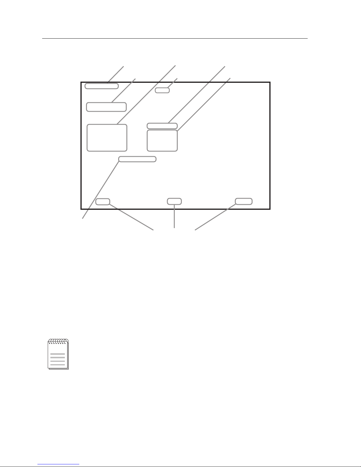
Figure 1. Example of a Local Management Screen
The following list explains each of the Local Management fields.
Event Message Field
This field briefly displays messages that indicate if a Local Management
procedure was executed correctly or incorrectly, that changes were saved or not
saved to Non-Volatile Random Access Memory (NVRAM), or that a user did not
have access privileges to an application.
Firmware Revision: XX.XX.XX
General Configuration
screen
BOOTPROM Revision: XX.XX.XX
MAC Address:
IP Address:
Subnet Mask:
Default Gateway:
TFTP Gateway IP Addr:
Device Date:
Device Time:
Screen Refresh Time:
Screen Lockout Time:
Clear NVRAM [NO]
Device Uptime XX D XX H XX M
Module Type: 9X5XX
Slot Number:
X
IP Fragmentation [ENABLED]
Operational Mode: [802.1D SWITCHING]
Event Message Field
Display Field
Input Fields
Selection Field
Command Fields
Display Fields
9X5XX LOCAL MANAGEMENT
Event Message Line
RETURNSAVE
05/01/98
14:23:00
30 sec.
15 min.
EXIT
00-00-ID-00-00-00
0.0.0.0
255.255.0.0
NONE DEFINED
0.0.0.0
Heading
Module Type &
Slot Number
Only the password, configuration, and status screens have event message fields.
NOTE
Page 23

7
Local Management: Overview, Setup, and Navigation
Table 3 describes the most common event messages. Event messages related to
specific Local Management applications are described with those applications
throughout this manual.
Heading
The heading will indicate the module name, the same as listed next to Module
Type.
Module Type and Slot Number
These fields display only when a module is being accessed through Local
Management. The module type is displayed and the chassis slot number of the
module is displayed. A chassis screen will not display these fields.
Display Fields
Display fields cannot be edited. These fields may display information that never
changes, or information that may change as a result of Local Management
operations, user selections, or network monitoring information. In the screens
shown in this guide, the characters in the display fields are in plain type (not
bold). In the field description, the field is identified as being “read-only”.
Input Fields
Input Fields require the entry of keyboard characters. IP addresses, subnet mask,
default gateway and device time are examples of input fields. In the screens
shown in this guide, the characters in the input fields ar e in bold type. In the field
description, the field is identified as being “modifiable”.
Selection Fields
Selection fields provide a series of possible values. Only applicable values appear
in a selection field. In the screens shown in this guide, the selections display
within brackets and are in bold type. In the field description, the f ield is identifi ed
as being either “selectable” when there are more than two possible values, or
“toggle” when there are only two possible values.
Table 3. Event Messages
Message What It Means
SAVED OK One or more fields were modified, and saved to
NVRAM.
NOT SAVED?--PRESS SAVE
TO KEEP CHANGES
Attempting to exit the LM Screen after one or more
fields were modified, but not saved to NVRAM.
NOTHING TO SAVE The SAVE command was executed, but no changes
were made that required saving.
Page 24

Local Management: Overview, Setup, and Navigation
8
Command Fields
Command fields are located at the bottom of Local Management Screens.
Command fields are used to exit Local Management Screens, save Local
Management entries, or navigate to the next sequence in the same screen. In the
screens shown in this guide, the characters in this field are all UPPER CASE and
in bold type. In the field descripti on, the f ield is identified as being a “command”
field.
Modifying Fields and User Privileges
To modify fields on this module, you must have read-write or super-user
privileges. If you have read-only privileges, you can view information; however,
you cannot modify any fields. For more information about user privileges and
community names, see “SNMP Community Names Screen” on page 29.
Navigating Local Management Screens
The Local Management application consists of a series of menu screens. Navigate
through Local Management by selecting items from the menu screens.
The 9X5XX-series modules support two modes of switch operation:
• 802.1Q Switching (802.1Q port-based VLANs)
• SecureFast VLAN (Cabletron Systems SecureFast Switching)
Figure 2 shows the hierarchy of the Local Management Screens.
Set the switch operational mode in the General Configuration Screen (see the
“General Configuration Screen” on page 23).
If You Choose the
Following Operational Mode:
You Will See the Follow ing
Screens (Figure 2):
802.1Q Switching mode All screens (both bold and italic)
SecureFast VLAN mode Only the screens displayed in bold
Page 25

9
Local Management: Overview, Setup, and Navigation
Figure 2. LM Screen Hierarchy
Module
Menu
Password
Module
Configuration
Menu
General Configuration Screen
Port Configuration
Screen
Switch Configuration
Screen
Network Tools
Broadcast Suppression
Configuration Screen
Ethernet
Configuration Screen
802.1 Configuration
Menu Screen
Module
Statistics
Menu Screen
Switch Statistics Screen
Interface Statistics Screen
RMON Statistics Screen
GARP
Configuration Menu
Screen
802.1Q VLAN
Configuration Menu
Screen
System Resources Screen
Flash Download Screen
802.1 Priority
Configuration Menu Screen
SmartTrunking
Configuration Screen
Redirect
Configuration
Menu
SNMP Configuration Menu
SNMP Community Names Screen
SNMP Traps Screen
GARP Configuration Screen
GMRP Configuration Screen
Layer 3 Extensions
Menu Screen
IGMP/VLAN Configuration
Screen
802_1Q
Acces Control List Screen
Backplane
Menu Screen
Backplane Status/
Utilization
Chassis Backplane
Utilization
Module/VLAN
Configuration Screen
Port Assignment
Configuration Screen
VLAN Forwarding
Configuration Screen
Port Filtering
Configuration Screen
VLAN Classification
Configuration Screen
Port Priority
Configuration Screen
Advanced Port Priority
Configuration Screen
Priority Classification
Configuration Screen
Transmit Queues
Configuration Screen
Ethernet Interface
Configuration
Port Redirect
Configuration Screen
VLAN Redirect
Configuration Screen
Rate Limiting Configuration
Gigabit Ethernet
Specific Configuration
Ethernet Port
Configuration
Page 26

Local Management: Overview, Setup, and Navigation
10
The 9H532-24, 9H533-24, 9H531-24, and 9H539-24
Modules
Each module is a 24-port switching module:
• 9H532-24 – 24 10Base-T/100Base-TX ports (RJ45 connectors)
• 9H533-24 – 24 10/100 Ethernet ports (two RJ21 Telco connectors)
• 9H531-24 – 24 100Base-FX ports, multimode fiber (mini MTRJ transceivers)
• 9H539-24 – 24 100Base-FX single mode fiber ports via mini MTRJ transceivers
Each module can operate in either full duplex or half duplex mode. 100Base-FX
supports 100 Mbps speed at both half and full duplex.
Auto-negotiation (available only with the 9H532-24 and 9H533-24 modules)
provides support for 10 Mbps and 100 Mbps speeds at both half and full duplex.
This feature allows the module to automatically use the fastest rate supported by
the device at the other end (either 10 Mbps or 100 Mbps at either half or full
duplex). To negotiate duplex, both the 9H532-24/9H533-24 and the attached
device must be configured for auto-n egotiation. If on ly the 9H532-2 4/9H533-2 4 is
configured for auto-negotiation, the modul e will set the c onnection to half duplex
at either the 10 Mbps or 100 Mbps rate. This techno logy is simil ar to h ow modems
negotiate transmission speed, finding the highest transmission rate possible.
Similarly, auto-negotiation determines the highest common speed between two
devices and communicates at that speed. If no common speed is detected, the
device will be partitioned.
Module Interface Codes
The 9H532-24, 9H533-24, 9H531-24, and 9H539-24 Modules have 40 interfaces.
Table 4 lists the identifying number, name, and description of each interface.
Table 4. 9H532-24, 9H533-24, 9H531-24, and 9H539-24 Module Interface Codes
Interface
Number
Interface
Name
Interface
Description
1 FENET1 Fast Ethernet Front Panel Port 1
2 FENET2 Fast Ethernet Front Panel Port 2
3 FENET3 Fast Ethernet Front Panel Port 3
4 FENET4 Fast Ethernet Front Panel Port 4
5 FENET5 Fast Ethernet Front Panel Port 5
6 FENET6 Fast Ethernet Front Panel Port 6
Page 27

11
Local Management: Overview, Setup, and Navigation
Use the numbers listed in T able 4 to configure each module’s def ault interface (see
the “General Configuration Screen” on page 23).
7 FENET7 Fast Ethernet Front Panel Port 7
8 FENET8 Fast Ethernet Front Panel Port 8
9 FENET9 Fast Ethernet Front Panel Port 9
10 FENET10 Fast Ethernet Front Panel Port 10
11 FENET11 Fast Ethernet Front Panel Port 11
12 FENET12 Fast Ethernet Front Panel Port 12
13 FENET13 Fast Ethernet Front Panel Port 13
14 FENET14 Fast Ethernet Front Panel Port 14
15 FENET15 Fast Ethernet Front Panel Port 15
16 FENET16 Fast Ethernet Front Panel Port 16
17 FENET17 Fast Ethernet Front Panel Port 17
18 FENET18 Fast Ethernet Front Panel Port 18
19 FENET19 Fast Ethernet Front Panel Port 19
20 FENET20 Fast Ethernet Front Panel Port 20
21 FENET21 Fast Ethernet Front Panel Port 21
22 FENET22 Fast Ethernet Front Panel Port 22
23 FENET23 Fast Ethernet Front Panel Port 23
24 FENET24 Fast Ethernet Front Panel Port 24
25-37 INB Internal Network Bus
38 HOST Host Data Port
39 SMB-10 10 Mbps System Management Bus
40 SMB-1 1 Mb ps System Management Bus
Table 4. 9H532-24, 9H533-24, 9H531-24, and 9H539-24 Module Interface Codes (Continued)
Interface
Number
Interface
Name
Interface
Description
Page 28

Local Management: Overview, Setup, and Navigation
12
The 9E531-24 Module
The 9E531-24 module is a switching module that provides 24 10BASE-FL ports
via MTRJ connectors. The module can operate in either full duplex or half duplex
mode.
Module Interface Codes
The 9E531-24 module has 40 interfaces. Table 4 lists the identifying number , name,
and description of each interface.
Table 5. 9E531-24 Module Interface Codes
Interface
Number
Interface
Name
Interface
Description
1 ENET1 Ethernet Front Panel Port 1
2 ENET2 Ethernet Front Panel Port 2
3 ENET3 Ethernet Front Panel Port 3
4 ENET4 Ethernet Front Panel Port 4
5 ENET5 Ethernet Front Panel Port 5
6 ENET6 Ethernet Front Panel Port 6
7 ENET7 Ethernet Front Panel Port 7
8 ENET8 Ethernet Front Panel Port 8
9 ENET9 Ethernet Front Panel Port 9
10 ENET10 Ethernet Front Panel Port 10
11 ENET11 Ethernet Front Panel Port 11
12 ENET12 Ethernet Front Panel Port 12
13 ENET13 Ethernet Front Panel Port 13
14 ENET14 Ethernet Front Panel Port 14
15 ENET15 Ethernet Front Panel Port 15
16 ENET16 Ethernet Front Panel Port 16
17 ENET17 Ethernet Front Panel Port 17
18 ENET18 Ethernet Front Panel Port 18
19 ENET19 Ethernet Front Panel Port 19
Page 29

13
Local Management: Overview, Setup, and Navigation
Use the numbers listed in T able 5 to configure each module’s def ault interface (see
the “General Configuration Screen” on page 23).
20 ENET20 Ethernet Front Panel Port 20
21 ENET21 Ethernet Front Panel Port 21
22 ENET22 Ethernet Front Panel Port 22
23 ENET23 Ethernet Front Panel Port 23
24 ENET24 Ethernet Front Panel Port 24
25-37 INB Internal Network Bus
38 HOST Host Data Port
39 SMB-10 10 Mbps System Management Bus
40 SMB-1 1 Mb ps System Management Bus
Table 5. 9E531-24 Module Interface Codes (Continued)
Interface
Number
Interface
Name
Interface
Description
Page 30

Local Management: Overview, Setup, and Navigation
14
The 9G536-04 Module
The 9G536-04 is 4-port Gigabit Ethernet switching module with:
• 4 Front-panel gigabit Ethernet ports
• 2 Internal Network Bus (INB) backplane ports
Module Interface Codes
The 9G536-04 module has 20 interfaces. Table 6 lists the identifying number,
name, and description of each interface.
Use the numbers listed in Table 6 to configure the module’s default interface (see
the “General Configuration Screen” on page 23).
Table 6. 9G536-04 Module Interface Codes
Interface
Number
Interface
Name
Interface
Description
1 ENET1 Gigabit Ethernet Front Panel Port 1
2 ENET2 Gigabit Ethernet Front Panel Port 2
3 ENET3 Gigabit Ethernet Front Panel Port 3
4 ENET4 Gigabit Ethernet Front Panel Port 4
5-17 INB Internal Network Bus
18 HOST Host Data Port
19 SMB-10 10 Mbps System Management Bus
20 SMB-1 1 Mb ps System Management Bus
If Gigabit front panel ports 3 and 4 are not used, then the interface numbers for
the INB will start with 3.
NOTE
Page 31

15
Local Management: Overview, Setup, and Navigation
The 9H532-17/9H531-17 Modules
The 9H532-17 and 9H531-17 are 17-port Ethernet switching modules with:
• 16 10/100 UTP (Category 5) Ethernet ports
• One VHSIM High Speed Uplink Module
Module Interface Codes
The 9H532-17 and 9H531-17 modules have 34 interfaces. Table 7 lists the
identifying number, name, and description of each interface.
Table 7. 9H532-17/9H531-17 Module Interface Codes
Interface
Number
Interface
Name
Interface
Description
1 ENET1 Ethernet Front Panel Port 1
2 ENET2 Ethernet Front Panel Port 2
3 ENET3 Ethernet Front Panel Port 3
4 ENET4 Ethernet Front Panel Port 4
5 ENET5 Ethernet Front Panel Port 5
6 ENET6 Ethernet Front Panel Port 6
7 ENET7 Ethernet Front Panel Port 7
8 ENET8 Ethernet Front Panel Port 8
9 ENET9 Ethernet Front Panel Port 9
10 ENET10 Ethernet Front Panel Port 10
11 ENET11 Ethernet Front Panel Port 11
12 ENET12 Ethernet Front Panel Port 12
13 ENET13 Ethernet Front Panel Port 13
14 ENET14 Ethernet Front Panel Port 14
15 ENET15 Ethernet Front Panel Port 15
16 ENET16 Ethernet Front Panel Port 16
17 ENET17 VHSIM Front Panel Port
18 ENET18 VHSIM Front Panel Port
19-31 INB Internal Network Bus
Page 32

Local Management: Overview, Setup, and Navigation
16
32 HOST Host Data Port
33 SMB-10 10 Mbps System Management Bus
34 SMB-1 1 Mb ps System Management Bus
Table 7. 9H532-17/9H531-17 Module Interface Codes (Continued)
Interface
Number
Interface
Name
Interface
Description
If only one physical po rt i s b ei ng used on the VHSIM, then th e i nterface numbers
for the INB wi ll start with 18.
NOTE
Page 33

17
Local Management: Overview, Setup, and Navigation
The 9H532-18/9H531-18 Modules
The 9H532-18 and 9H531-18 are 18-port Ethernet switching modules with:
• 16 10/100 UTP (Category 5) Ethernet ports
• 2 SMF or MMF Gigabit Uplink Modules
Module Interface Codes
The 9H532-18 and 9H531-18 modules have 34 interfaces. Table 8 lists the
identifying number, name, and description of each interface.
Table 8. 9H532-18/9H531-18 Module Interface Codes
Interface
Number
Interface
Name
Interface
Description
1 ENET1 Ethernet Front Panel Port 1
2 ENET2 Ethernet Front Panel Port 2
3 ENET3 Ethernet Front Panel Port 3
4 ENET4 Ethernet Front Panel Port 4
5 ENET5 Ethernet Front Panel Port 5
6 ENET6 Ethernet Front Panel Port 6
7 ENET7 Ethernet Front Panel Port 7
8 ENET8 Ethernet Front Panel Port 8
9 ENET9 Ethernet Front Panel Port 9
10 ENET10 Ethernet Front Panel Port 10
11 ENET11 Ethernet Front Panel Port 11
12 ENET12 Ethernet Front Panel Port 12
13 ENET13 Ethernet Front Panel Port 13
14 ENET14 Ethernet Front Panel Port 14
15 ENET15 Ethernet Front Panel Port 15
16 ENET16 Ethernet Front Panel Port 16
17 ENET17 Gigabit Front Panel Port
18 ENET18 Gigabit Front Panel Port
19-31 INB Internal Network Bus
Page 34

Local Management: Overview, Setup, and Navigation
18
32 HOST Host Data Port
33 SMB-10 10 Mbps System Management Bus
34 SMB-1 1 Mb ps System Management Bus
Table 8. 9H532-18/9H531-18 Module Interface Codes (Continued)
Interface
Number
Interface
Name
Interface
Description
If only one Gigabit port is being utilized, then the interface numbers for the INB
will start with 18.
NOTE
Page 35

19
Local Management: Overview, Setup, and Navigation
Module P assword Screen
The Module Password Screen, Figure 3, controls access to Local Management.
Whenever a user connects to a module, the Module Password Screen displays.
Before continuing, a user must enter a password (community name), which is
compared to the previously-stored passwords. The level of access allowed a user
depends on the password.
A user’s password is one of the community names specified in the SNMP
Community Names Configuration Screen. Access to certain Local Management
capabilities depends on the degree of access accorded that community name.
Figure 3. Module Password Screen
If a user enters an invalid password, the terminal beeps and the cursor returns to
the beginning of the password entry field.
Entering a valid password causes the associated access level to display at the
bottom of the screen and the Device Menu Screen to display.
If no activity oc c urs for several mi nut es, the Local Manage ment Password Scre en
redisplays and the password has to be reentered.
NOTE
SmartSwitch 9000 Local Management
Cabletron Systems, Incorporated
P.O. Box 5005
Rochester, N.H. 03866-5005 USA
(603) 332-9400
(c) Copyright CABLETRON Systems, Inc. 1997
Module Serial Number: 1234567890AB
Module Hardware Revision: 12A
Module Firmware Revision: 00.00.00
Module BOOTPROM Revision: 00.00.00
Enter Password
Page 36

Local Management: Overview, Setup, and Navigation
20
Module Menu Screen
The Module Menu Screen, Figure 4, is the access point to Local Management for
all modules installed in the SmartSwitch 9000 chassis.
Figure 4. Module Menu Screen
• For information regarding the Module Configuration Menu Screen,
see page 21.
• For information regarding the Module Statistics Menu Screen, see page 133.
• For information regarding Network Tools, see page 144.
SmartSwitch 9000 Local Management
Module Menu
Module Name: 9H531-24 Firmware Revision: 1.00.00
Slot Number: 5 BOOTPROM Revision: 1.00.00
MODULE CONFIGURATION
MODULE STATISTICS
NETWORK TOOLS
EXIT RETURN
Page 37

21
Local Management: Overview, Setup, and Navigation
Module Configuration Menu Screen
The Module Configuration Menu Screen, Figure 5, provides access to Local
Management Screens that allow you to configure and monitor operating
parameters, modify SNMP community names, set SNMP traps, configure switch
parameters and configure ports.
To access the Module Configuration Menu Screen from the Module Menu Screen,
use the arrow keys to highlight the MODULE CONFIGURATION menu item
and press ENTER. The Module Configuration Screen displays.
Figure 5. Module Configuration Menu Screen
SmartSwitch 9000 Local Management
Module Configuration Menu
Module Name: 9H531-24 Firmware Revision: 01.00.00
Slot Number: 13 BOOTPROM Revision: 01.00.00
GENERAL CONFIGURATION
SNMP CONFIGURATION MENU
SYSTEM RESOURCES
FLASH DOWNLOAD
PORT CONFIGURATION Menu
802.1 CONFIGURATION MENU
LAYER 3 EXTENSIONS MENU
EXIT RETURN
The Slot Number field displays when this screen refers to a module installed in a
SmartSwitch 9000 chassis .
The SecureFast VLAN CONFIGURATION is displayed only if operating in
SFVLAN mode.
The SWITCH CONFIGURATION only to be displayed if operating in 802.1d
Switch Mode.
The General Configuration, SNMP Community Names, Full Duplex
Configuration and SNMP Traps Screens are module specific screens.
NOTES
Page 38

Local Management: Overview, Setup, and Navigation
22
• For information regarding the General Configuration Screen, see page 23.
• For information regarding the SNMP Configuration Menu Screen,
see page 28.
• For information regarding the System Resources Screen, see page 36.
• For information regarding the Flash Download Screen, see page 38.
• For information regarding the Port Specific Configuration Screen,
see page 42.
• For information regarding the 802.1 Configuration Menu Screen,
see page 71.
• For information regarding the Layer 3 Extensions Menu Screen, see
page 128.
Page 39

23
Local Management: Overview, Setup, and Navigation
General Configuration Screen
The General Configuration Screen, Figure 6, displays information about the
selected module and allows a user to set the following general parameters:
• Module Date and Time
• Screen Refresh and Screen Lockout Time
• Host IP Address
•Subnet Mask
• Default Gateway and Interface
• TFTP Gateway IP Address
T o access the General Configuration Scr een from the Module Configuration Menu
Screen, use the arrow keys to highlight the GENERAL CONFIGURATION menu
item and press ENTER.
Figure 6. General Configuration Screen
SmartSWITCH 9000 Local Management
General Configuration
Module Name: 9H531-24 Firmware Revision: 01.00.00
Slot Number: 11 BOOTPROM Revision: 01.00.00
Module Serial #: 926001101046 Module Date: 07/22/1999
Module Board Revision: 046 Module Time: 08:53:49
Screen Refresh Time: 03 sec
Screen Lockout Time: 15 min
Device Uptime: 0 D 20 H 50 M Operational Mode: [802.1 SWITCHING]
Clear Persistent Memory: [NO] IP Address: xxx.xxx.xxx.xxx
Subnet Mask: 255.255.0.0
IP Fragmentation: [DISABLED] Default Gateway: NONE DEFINED
Default Interface: NONE DEFINED
Base MAC Address: 00-E0-63-23-4B-46
TFTP Gateway IP: 0.0.0.0
SAVE EXIT RETURN
Page 40

Local Management: Overview, Setup, and Navigation
24
General Configuration Screen Fields
The following information briefly explains each General Configuration Screen
field.
Module Serial #
This field displays the serial number of the selected module.
Module Board Revision
This field displays the version number of the selected module.
Device Uptime
This field displays the total time that the device has been operating.
Clear Persistent Memory (Toggle)
•Yes
•No
IP Fragmentation (Toggle)
This field enables or disables IP Fragmentation. The default set ting for this fi eld is
ENABLED. If the module will be bridged to an FDDI ring within the chassis, IP
Fragmentation should be enabled. If IP Fragmentation is disabled, all FDDI
frames that exceed the maximum Ethernet frame size will be discarded. For
details on enabling or disabling IP Fragmentation, see “Enabling/Disabling IP
Fragmentation” on page 27.
Module Date (Modifiable)
This field contains a value that the module r ecognizes as the curr ent date. To enter
a new date, highlight the field and enter the date in MM/DD/YYYY format. The
month and day portion of the date must include two digits. Therefore, enter a
leading zero for months January through September, and for dates less than 10.
For example, for June 4, 1999, enter 06/04/1999 (slashes are optional). If slashes
are not entered to separate the month, day, and year values, the first eight digits
entered in this field represent an entry (i.e., 06041999).
Module Time (Modifiable)
This field contains a value that the module recognizes as the current time. To enter
a new time, highlight the field and enter the time in HH:MM:SS format. Notice
that there is no AM/PM indic ator. Enter time based upon a 24 hour clock. For 4:07
p.m., enter 16:07:00 (colons are optional). If colons are not entered to separate the
hours, minutes, and seconds values, the first six digits entered in this field
represent an entry (i.e., 160700). For 6:12 a.m., enter 6:12:00 or 06120.
Page 41

25
Local Management: Overview, Setup, and Navigation
Screen Refresh Time (Modifiable)
This field contains the rate at which the module’s screens are updated. This
setting determines how frequently (in seconds) information is updated on the
screen. To enter a new refresh rate, highlight the field and enter a number. The
default refresh rate is 3 seconds. The range is 3 - 99 seconds.
Screen Lockout Time (Modifiable)
This field contains the maximum number of minutes that the Local Management
application displays a module’s screen while pending input or action fr om a user.
For example, if a user enters a 5 in this field, that user has up to five minutes to
respond, in some fashion, to each of the specified module’s Local Management
screens. In our example, after five minutes of “idleness” (no input or action), the
Local Management application terminate s the sess ion on the select ed module a nd
the Slot Selection Screen reappears. To enter a new lockout time, highlight the
field and enter a number. The default lockout time is 15 minutes. The range is
1 - 30 minutes.
Operational Mode (Selectable)
This field sets the module to one of the following:
• 802.1 Switching
• SecureFast
IP Address (Modifiable)
This field contains the Internet Protocol addr ess cu rr ently assig ned to the select ed
module. Set this field according to network requirements. Highlight the Host IP
address field and enter the desired IP address using dotted decimal notation (4
decimal values between 1 and 255 separated by periods) as follows:
255.255.255.255
(255 is the maximum number that a user can enter in any of the four segments.
The default is 0.0.0.0 .) This address can be used by any of the system interfaces
on the module.
The module’s default da te and time settings are indetermi nate. The internal
calendar and clock begin running as soon as the user installs the module.
NOTE
Page 42

Local Management: Overview, Setup, and Navigation
26
Subnet Mask (Modifiable)
This field contains the subnet mask for the selected module. A subnet mask
“masks out” the network bits of the IP address by setting the bits in the mask to 1
when the network treats the corresponding bits in the IP address as part of the
network or subnetwork address, or to 0 if the corresponding bit identifies the
host. The default subnet mask uses the first two portions of the IP address to
identify the network id, leaving the rest of the IP address to identify specific
nodes. To enter a new subnet mask, highlight the field and enter a new value
using dotted decimal notation (4 decimal values between 1 and 255 separated by
periods) as follows:
255.255.255.255
(The Subn et Mask field defaults to the natural mask value, based on the IP
address that was entered for the device.)
Default Gateway (Modifiable)
This field contains the IP address of the device to which all packets addressed to
an unknown network or host are sent. If a Default Gateway is not configur ed, any
packets that are addressed to an unknown network or host will be dropped. This
field is not defined until a user enters an appropriate value using dotted decimal
notation (4 decimal values between 1 and 255 separated by periods).
Default Interface (Toggle)
This field contains the number that represents the interface that is connected to
the module’s Default Gateway. In some instances, dissimilar modules have
different corresponding interface numbers. For example, if a user is assigning a
default interface to a 9T122-24 module and enters a 3, then the default interface is
the Flexible Network Bus. However, if a user is assigning a default interface to a
9F310-02 module and enters a 3, then the default interfac e is the Internal Net work
Bus. The default is NONE, meaning no default interface selected.
Base MAC Address
This field displays the MAC Address of the selected module. This is the MAC
Address of the SMB-10 interface.
TFTP Gateway IP (Modifiable)
This field displays the IP address of the router that connects to or is closest to the
module. Configure this address when a user is performing TFTP downloads in a
routed environment (if proxy ARP is disabled on the router).
The Default Interface field becomes active after a user enters an IP address in the
Default Gateway field .
NOTE
Page 43

27
Local Management: Overview, Setup, and Navigation
Enabling/Disabling IP Fragmentation
To enable or disable IP fragmentation, proceed as follows:
1. Use the arrow keys to highlight the IP Fragmentation field.
2. Press the Space Bar to choose either ENABLED or DISABLED.
3. Use the arrow keys to highlight the SAVE command.
4. Press ENTER. The Event Message Field displays “SAVED OK”.
If the module is being bridged to an FDDI ring, for example, using an optional
HSIM-F6, IP Fragmentation should be enabled. If it is disabled, all FDDI frames
that exceed the maximum Ethernet fram e size will be discarded.
NOTE
Page 44

Local Management: Overview, Setup, and Navigation
28
SNMP Configuration Menu Screen
The SNMP Configuration Menu Screen, Figure 7, provides access to the SNMP
Community Names Configuration Screen, the SNMP Traps Configuration Screen,
and the Access Control List Screen.
To access the SNMP Configuration Menu Screen from the Module Configuration
Menu Screen, use the arrow keys to highlight the SNMP CONFIGURATION
MENU item and press ENTER. The SNMP Configuration Menu Screen displays.
Figure 7. SNMP Configuration Menu Screen
• For information regarding the SNMP Community Names Screen,
see page 29.
• For information regarding the SNMP Traps Screen, see page 31.
• For information regarding the Access Control Screen, see page 34.
SmartSwitch 9000 Local Management
SNMP Configuration Menu
Module Name: 9H531-24 Firmware Revision: 01.00.00
Slot Number: 5 BOOTPROM Revision: 01.00.00
SNMP COMMUNITY NAMES
SNMP TRAPS
ACCESS CONTROL
EXIT RETURN
Page 45

29
Local Management: Overview, Setup, and Navigation
SNMP Community Names Screen
The SNMP Community Names Screen, Figure 8, allows a user to modify module
community names, but not chassis community names. Community names act as
passwords to Local Management and are agents of security access to the module.
Access to the module is controlled by enacting any of three different levels of
security authorization (read-only, read-write, and super-user).
To access the SNMP Community Names Configuration Screen from the SNMP
Configuration Menu Screen, use the arrow keys to highlight the SNMP
COMMUNITY NAMES CONF IGURATION menu item and press ENTER. The
SNMP Community Names Configuration Screen displays.
Figure 8. SNMP Community Names Screen
Super-User access gives a user full management privileges, allows existing
passwords to be changed, as well as all modifiable MIB objects.
NOTE
SmartSwitch 9000 Local Management
SNMP Community Names
Module Name: 9H531-24 Firmware Revision: 01.00.00
Slot Number: 5 BOOTPROM Revision: 01.00.00
Community Name Access Policy
public read-only
public read-write
public super-user
SAVE EXIT RETURN
Page 46

Local Management: Overview, Setup, and Navigation
30
SNMP Community Names Screen Fields
The following information briefly explains each SNMP Community Names
Screen field.
Community Name (Modifiable)
This field displays a user-defined name through which a user accesses chassis
management. Any community name assigned here acts as a password to
Local/Remote Management.
Access Policy (Read-Only)
This field indicates the access accorded each community name. Possibl e selections
are as follows:
read-only This community name allows read-only access to the chassis MIB
objects, and excludes access to security-protected fields of readwrite or super-user authorization.
read-write This community name allows read and write access to the chassis
MIB objects, excluding security protected fields for super-user
access only.
super-user This community name permits read-write access to the chassis
MIB objects and allows a user to change all modi fi able paramet ers,
including community names, IP addresses, traps, and SNMP
objects.
Page 47

31
Local Management: Overview, Setup, and Navigation
SNMP Traps Screen
The SNMP Traps Screen, Figure 9, allows a user to send messages to multiple
Network Management Stations to alert users of status changes.
To access the SNMP Traps Configuration Screen from the SNMP Configuration
Menu Screen, use the arrow keys to highlight the SNMP TRAPS
CONFIGURATION menu item and press ENTER. The SNMP Traps
Configuration Screen displays.
Figure 9. SNMP Traps Screen
SmartSwitch 9000 Local Management
SNMP Traps
Module Name: 9H531-24 Firmware Revision: 01.00.00
Slot Number: 5 BOOTPROM Revision: 01.00.00
Chassis Trap Agent: [ENABLED]
Trap Destination Trap Community Name Enable Traps
0.0.0.0 Public [NO]
0.0.0.0 Public [NO]
0.0.0.0 Public [NO]
0.0.0.0 Public [NO]
0.0.0.0 Public [NO]
0.0.0.0 Public [NO]
0.0.0.0 Public [NO]
0.0.0.0 Public [NO]
SAVE EXIT RETURN
Page 48

Local Management: Overview, Setup, and Navigation
32
SNMP Traps Screen Fields
The following information briefly explains each SNMP Traps Screen field.
Chassis Trap Agent (Toggle)
This field enables/disables specific chassis traps to the network management
station. The field toggles between ENABLED and DISABLED. The default is
DISABLED.
Trap Destination (Modifiable)
This field indicates the IP a ddr ess of the workstation to receive trap alarms. Up to
eight different destinations can be defined.
Trap Community Name (Modifiable)
This field displays the Community Name incl uded in the trap message sent to the
Network Management Station with the associated IP address.
Enable Traps (Toggle)
This field enables transmission of the traps to the network management station
with the associated IP address. This field toggles between [YES] and [NO].
Configuring the Trap Table
To configure the Trap Table:
1. Use the arrow keys to highlight the appropriate Trap Destination field.
2. Enter the IP address of the workstation that is to receive traps. IP address
entries must follow the DDN format. For example: 000.000.000.000
3. Press ENTER. If an invalid entry is entered, the message “INVALID IP
ENTERED” displays in the Event Message Line.
4. Use the arrow keys to highlight the Trap Community Name field. Enter the
community name.
5. Press ENTER.
6. Use the arrow keys to highlight the Enable Traps field.
7. Press the Space Bar to choose either of the following:
• YES - Send alarms from the module to the workstation
• NO - Prevent alarms from being sent to the workstation
8. Use the arrow keys to highlight the SAVE command and press ENTER. The
message “SAVED OK” displays on the screen.
Page 49

33
Local Management: Overview, Setup, and Navigation
The designated workstations now receive traps.
Exiting without saving causes a “NOT SAVED?” message to appear above the
SAVE command. Edits are lost if they are not saved before exiting.
NOTE
Page 50

Local Management: Overview, Setup, and Navigation
34
Access Control Screen
The Access Control Screen, Figure 10, allows a user to specify the IP addresses of
SNMP management stations that are allowed to remotely manage a device.
IP addresses and access control list state are persistent. Clearing NVRAM
removes all IP entries and returns the access control state to Disabled. While
locally connected to the COM port of the chassis or module, ACL will not restrict
access to local management. (Distributed management must be considered.)
Figure 10. Access Control Screen
SmartSwitch 9000 Local Management
Access Control
Module Name: 9H531-24 Firmware Revision: 01.00.00
Slot Number: 5 BOOTPROM Revision: 01.00.00
Access Control Lists: [ENABLED]
IP Addresses
0.0.0.0 0.0.0.0
0.0.0.0 0.0.0.0
0.0.0.0 0.0.0.0
0.0.0.0 0.0.0.0
0.0.0.0 0.0.0.0
0.0.0.0 0.0.0.0
0.0.0.0 0.0.0.0
0.0.0.0 0.0.0.0
SAVE EXIT RETURN
Page 51

35
Local Management: Overview, Setup, and Navigation
Access Control Screen Fields
The following information briefly explains each Access Control Screen field.
Access Control Lists (Toggle)
This field can be either of the following:
• Enabled - Host access is restricted to the 16 IP addresses found in the LM
Screen. If a user enters an invalid IP address, this field will not toggle to
Enabled.
• Disable d (default) - Host access is not restricted.
IP Addresses (Read-only)
This field displays the addresses of management stations that are allowed to
remotely manage a device.
Page 52

Local Management: Overview, Setup, and Navigation
36
System Resources Screen
The System Resources Screen, Figure 11, displays information about current and
available resources on the module.
Figure 11. System Resources Screen
SmartSwitch 9000 Local Management
System Resources
Module Name: 9H531-24 Firmware Revision: 01.00.00
Slot Number: 13 BOOTPROM Revision: 01.00.00
CPU Type : i960 HD 33MHz
Flash Memory Installed: 8 MB Available: 5953536 Bytes
DRAM Installed: 32 MB Available: 21843656 Bytes
NVRAM Installed: 341 KB Available: 338699 Bytes
Current Switch Utilization: 0 %
Peak Switch Utilization: 0 %
Reset Peak Switch Utilization: [NO]
SAVE EXIT RETURN
Page 53

37
Local Management: Overview, Setup, and Navigation
System Resources Screen Fields
The following information briefly explains each System Resources Screen field.
Flash Memory Installed/Available (Read-only)
This field displays the size of Flash Memory and indicates how many bytes are
currently available.
DRAM Installed/Available (Read-only)
This field displays the size of dynamic random access memory (DRAM) and
indicates how many bytes are currently available.
NVRAM Installed/Available (Read-only)
This field displays the size of non-volat ile random acc ess m emory (NVRAM) and
indicates how many bytes are currently available. NVRAM stores user-entered
parameters such as IP addresses, subnet masks, default gateways, SNMP traps,
bridge configurations, and module specific configurations.
Current Switch Utilization (Read-only)
This field displays the per centage of the device switching capacity currentl y being
used.
Peak Switch Utilization (Read-only)
This field displays the peak percentage of device switching capacity used, since
the last reset.
Reset Peak Switch Utilization (Toggle)
This field resets the Peak Switch Utilization field, and is either of the following:
• Yes - Reset the Peak Switch field to the current system traffic.
• No - Do not reset the Peak Switch field to the current system traffic.
Setting the Reset Peak Switch Utilization
To set the Reset Peak Switch Utilization field to YES or NO, proceed as follows:
1. Use the arrow keys to highlight the Reset Peak Switch Utilization field .
2. Press the Space Bar to select YES or NO.
3. Use the arrow keys to highlight the SAVE command at the bottom of the
screen.
4. Press ENTER. The message “SAVED OK” displays and the Reset Peak
Utilization counter resets to zero.
Page 54

Local Management: Overview, Setup, and Navigation
38
Flash Download Configuration Screen
The Flash Download Configuration Screen, Figure 12, replaces the information
stored in the Flash memory with a new image file downloaded from a TFTP
server . Befor e downloading an image to the device, copy t he image to the network
TFTP server. Additionally, NVRAM parameters can be downloaded to a
designated configuration server or uploaded to a module using this feature.
To access the Flash Download Configuration Screen from the Module
Configuration Menu Screen, use the arrow keys to highlight the FLASH
DOWNLOAD CONFIGURATION menu item and then press ENTER. The Flash
Download Configuration Screen displays.
Figure 12. Flash Download Configuration Screen
This feature is supported in firmware versions greater than 1.12.00.
NOTE
SmartSwitch 9000 Local Management
Flash Download Configuration
Module Name: 9H531-24 Firmware Revision: 01.00.00
Slot Number: 13 BOOTPROM Revision: 01.00.00
Download Method: [RUNTIME]
Reboot After Download: [YES]
TFTP Gateway IP Addr: 0.0.0.0
Download Server IP: XXX.XXX.XXX.XXX
Download File Name: C:\IMAGES\SSX\11011.FLS
Last Image Server IP: XXX.XXX.XXX.XXX
Last Image File Name: C:\IMAGES\SSX\11011.FLS
Transfer Status: Transfer Successful
EXECUTE EXIT RETURN
Page 55

39
Local Management: Overview, Setup, and Navigation
Flash Download Configuration Screen Fields
The following information briefly explains each Flash Download Configuration
Screen field.
Download Method (Selectable)
This field indicates the download or upload method used by the device, and can
be one of the following:
• RUNTIME - The module attempts a TFTP download based on the IP address
and the file name entered in the fields at the bottom of the Flash Download
Configuration Screen. With the RUNTIME method, these additional fields are
displayed:
- Download Server IP (Modifiable) - This field is used to select the IP address
of the TFTP server to be used for the Flash download.
- Download File Name (Modifiable) - This field is used to sel ect the complete
TFTP server path and file name of the new image.
• DOWNLOAD CONFIG - Saves all NVRAM parameters to a specified
download server that can be accessed later using the UPLOAD CONFIG
option. With the DOWNLOAD CONFIG method, these additional fields are
displayed:
- Configuration Server IP (Modifiable) - This field is used to select the IP
address of the Configuration server to be used for the Flash download.
- Configuration File Name (Modifiable) - This field is used to select the
complete Configuration server path and file name of the new image.
• UPLOAD CONFIG - Sends NVRAM parameters back to the module. T o use the
UPLOAD CONFIG option, a user must first assign an IP address to the
module. With the UPLOAD CONFIG method, these additional fields are
displayed:
- Configuration Server IP (Modifiable) - This field is used to select the IP
address of the Configuration server to be used for the upload.
- Configuration File Name (Modifiable) - This field is used to select the
complete Configuration server path and file name of the new image.
Page 56

Local Management: Overview, Setup, and Navigation
40
Reboot After Download (Toggle) (Only available for the RUNTIME option)
This field notifies a user that the module will reboot after the download is
complete. This field toggles between the following:
• YES - The module reboots after the download is completed.
• NO - The module will cont inue using the existing firmwar e image. The module
stores the new firmware image in Flash memory. When the module is reset or
during the next power up, the module boots from Flash memory using the new
image.
TFTP Gateway IP Addr (Modifiable)
This field displays the IP address of the TFTP gateway defined in the General
Configuration Screen.
Last Image Server IP (Read-only)
This field displays the IP address of the server used for the previous Flash
Download.
Last Image File Name (Read-only)
This field displays the complete path and f ile name of the l ast i mage downloa ded
to Flash.
Transfer Status (Read-only)
This field displays the status of the current or most recent download or upload.
Using RUNTIME to Download an Image File
To download an image file using RUNTIME:
1. Use the arrow keys to highlight the Download Method field.
2. Press the Space Bar to select RUNTIME.
3. Use the arrow keys to highlight the Reboot After Download fie ld.
4. Press the Space Bar to select either of the following:
• YES - a user wants the module to reboot after the download is completed.
• NO - a user wants the module to store the new image in Flash memory until
the module is manually reset.
5. Use the arrow keys to highlight the TFTP Gateway IP Addr field.
6. Set the IP address of the TFTP gateway server (this defaults to the same IP
address as that set in the TFTP Gateway IP Addr field on the General
Configuration Screen).
Page 57

41
Local Management: Overview, Setup, and Navigation
7. Use the arrow keys to highlight the Download Server IP field.
8. Enter the IP address of the TFTP server using the standard quad dotted octet
format.
9. Use the arrow keys to highlight the Download File Name field.
10. Enter the complete path and file name of the image stored on the download
server.
11. Use the arrow keys to highlight EXECUTE at the bottom of the screen and
press ENTER. The message “RUNTIME DOWNLOAD. WILL COMMIT TO
FLASH.” displays in the event message line at the top of the screen. The new
image is downloade d into Flash memory.
Page 58

Local Management: Overview, Setup, and Navigation
42
Port Configuration Menu Screen
The Port Configuration Menu Screen, Figure 13, provides access to Local
Management Screens that allow you to configure Operational Mode and
Advertised Ability.
Figure 13. Port Configuration Menu Screen
• For information regarding the Ethernet Configuration Screen, see page 43.
• For information regarding the Gigabit Ethernet Specific Configuration
Screen, see page 51.
• For information regarding the HSIM/VHSIM Configuration Screen, see
page 53.
• For information regarding the Backplane Menu Screen, see page 54.
• For information regarding the Redirect Configuration Menu Screen, see
page 59.
• For information regarding the SmartTrunk Configuration Screen, see
page 65.
• For information regarding the Broadcast Suppression Screen, see page 68.
SmartSwitch 9000 Local Management
Port Configuration Menu
Module Name: 9H531-24 Firmware Revision: 01.00.00
Slot Number: 6 BOOTPROM Revision: 01.00.00
ETHERNET CONFIGURATION
GIGABIT ETHERNET SPECIFIC CONFIGURATION
HSIM/VHSIM CONFIGURATION
BACKPLANE MENU
REDIRECT CONFIGURATION MENU
SMARTTRUNK CONFIGURATION
BROADCAST SUPPRESSION
EXIT RETURN
Page 59

43
Local Management: Overview, Setup, and Navigation
Ethernet Interface Configuration Screen
The Ethernet Interface Configuration Screen, Figure 14, displays status
informatio n and allow s a user to co nfigure Operational Mode and Advertis ed
Ability for Ethernet and Gigabit Ethernet Screens.
Figure 14. Ethernet Interface Configuration Screen
SmartSwitch 9000 Local Management
Ethernet Interface Configuration
Module Name: 9H531-24 Firmware Revision: 01.00.00
Slot Number: 13 BOOTPROM Revision: 01.00.00
Intf Port PortType Link Speed Duplex Config FDX FC HDX FC
1 1 MTRJ-100FX No Link 100 Half Manual Sym On
2 1 MTRJ-100FX No Link 100 Half Manual Sym On
3 1 MTRJ-100FX No Link 100 Half Manual Sym On
4 1 MTRJ-100FX No Link 100 Half Manual Sym On
5 1 MTRJ-100FX No Link 100 Half Manual Sym On
6 1 MTRJ-100FX No Link 100 Half Manual Sym On
7 1 MTRJ-100FX No Link 100 Half Manual Sym On
8 1 MTRJ-100FX No Link 100 Half Manual Sym On
9 1 MTRJ-100FX No Link 100 Half Manual Sym On
10 1 MTRJ-100FX No Link 100 Half Manual Sym On
11 1 MTRJ-100FX No Link 100 Half Manual Sym On
12 1 MTRJ-100FX No Link 100 Half Manual Sym On
NEXT EXIT RETURN
Page 60

Local Management: Overview, Setup, and Navigation
44
Ethernet Interface Configuration Screen Fields
The following information briefly explains each Ethernet Interface Configuration
Screen field.
Intf (Read-Only)
This field displays the interface number.
Port (Read-Only)
This field displays the number of the physical port on the interface. For the front
panel ports on the 9X5XX-series modules, this will always be 1.
PortType (Read-Only)
This field displays the type of interface using the name of the Cabletron Systems
physical port type. For the Ethernet 10/100 ports in the 9H532-24, FE-100TX will
be displayed. If a Gigabit port is installed via the optional HSIM or VHSIM, the
interface displayed may be GE-1000SX or GE-1000LX.
Link (Read-Only)
This field indicates whether or not there is a physical connection from the port to
another device. One of the following values is displayed:
• Link – There is a link signal present and a valid physical connection to another
device.
• No Link – There is no link signal present and there is no valid physical
connection to another device.
Speed (Read-Only)
This field displays the current operational speed in Mbps. Display options are 10,
100 or 1000. If the port has not completed Auto-Negotiation, “NA” displays.
Duplex (Read-Only)
This field displays the current duplex setting. One of the following values is
displayed:
• Half – the port will operate in half duplex mode.
• Full – the port will operate in full duplex mode.
• NA – The port has not completed Auto-Negotiation.
Page 61

45
Local Management: Overview, Setup, and Navigation
Config (Read-Only)
This field displays whether Auto-Negotiation (AutoNeg) or Manual is enabled.
FDX FC (Read-Only)
This field displays the current full duplex flow control setting. Flow control is
used to manage the transmission between two devices, as specified by
IEEE 802.3x, to prevent receiving ports from being overwhelmed by frames from
transmitting devices. One of the following values is displayed:
•AsymRx
•AsymTx
•Off
•Sym
• NA - NA (Not Applicable) is displayed when the port does not support flow
control.
HDX FC (Read-Only)
This field displays the current half duplex flow control setting. Half duplex flow
control, also kn own as b ack pressure, is a collision-based flow control mechanism
used in half duplex configurations. The port will display either On, Off, or NA.
NA is displayed when the port does not support flow control.
In normal operation, front panel ports automatically establish a link with the
device at the other end of the segment without requiring user setup. However,
Local Management provides a user with the op tion of manually configuring that
port.
NOTE
Page 62

Local Management: Overview, Setup, and Navigation
46
Ethernet Port Configuration Screen
The Ethernet Port Configuration Screen, Figure 15, is used to change the operating
mode of a specific Ethernet inte rface , such a s th e speed, duplex, auto-negotiation,
advertised ability, and the flow cont r o l setti ngs. Optional Fast Ethernet or Gigabit
Ethernet ports are also configured on this screen.
To access the Ethernet Port Configuration Screen for a specific port from the
Ethernet Interface Configuration Screen, use the arrow keys to highlight the
desired Ethernet port and press ENTER. The Ethernet Port Configuration Screen
displays for the desired port.
Figure 15. Ethernet Port Configuration Screen
Auto-Negotiation is not supported on the 9H531-24 and 9H539-24 modules.
NOTE
SmartSwitch 9000 Local Management
Ethernet Port Configuration
Module Name: 9H531-24 Firmware Revision: 01.00.00
Slot Number: 13 BOOTPROM Revision: 01.00.00
Interface: 9 Physical Port: 1
Default Speed: [ 100]
Default Duplex: [Half]
Auto-Negotiation State: Not Supported
Advertised Ability: Not Applicable
Full Duplex Flow Control: [Symmetric]
Half Duplex Flow Control: [Enabled]
SAVE SAVE TO ALL PORTS EXIT RETURN
Page 63

47
Local Management: Overview, Setup, and Navigation
Ethernet Port Specific Configuration Fields
The following explains each Ethernet Port Specific Configuration Screen field.
Interface (Read-Only)
Displays the Interface number.
Physical Port (Read-Only)
Displays the number of the physical port on the interface.
Default Speed (Read-Only)
Displays the current operational speed in Mbps. The 9H532-24 can operate at 10
Mbps or 100 Mbps. The 9H531-24 and 9H539-24 modules operate at
100 Mbps.
Default Duplex (Toggle)
The choices are Half, for half duplex, or Full, for full duplex. If Auto-Negotiation
is disabled for the port, then the port defaults to operate in the setting displayed.
To choose the Default Duplex, see “Selecting and Changing Settings” on page 49.
Auto-Negotiation State (Toggle)
Determines whether Auto-Negotiation is Enabled or Disabled for the specific
port. During auto-negotiation, the port “tells” the device at the other end of the
segment what its capabilities ar e. If Auto-Negot iati o n is dis able d, the port reverts
to the speed, duplex and flow control settings specified by Defa ult Speed, Default
Duplex, Half Duplex Flow Control and Full Duplex Flow Control fields
respectively.
Advertised Ability (Selectable)
In normal operation, with all capabilities enabl ed, the port “adverti ses” that it has
the ability to operate in any mode. A user may choose to set up the port so that
only a portion of the available capabilities are advertised and the others are
disabled. The left field displays the advertised ability of the port, but only
becomes active on ports that have Auto-Negotiation enabled. The status of a
particular ability is displayed in the right field. The “T” in an ability stands for
twisted pair. Possible abilities are listed below. Not all choices listed below will be
available, as the module will display only the choices available to it.
• 10Base-T – 10 Mbps operation
• 10Base-TFD – 10 Mbps full duplex operation
• 100Base-TX – 100 Mbps operation
Auto-Negotiation is not supported on the 9H531-24 and 9H539-24 modules.
NOTE
Page 64

Local Management: Overview, Setup, and Navigation
48
• 100Base-TXFD – 100 Mbps full duplex operation
• 1000Base-X – 1000Base-SX or 1000Base-LX Gigabit Ethernet
• 1000Base-T – 1000 Base-T Gigabit Ethernet
• 1000Base-XFD – 1000Base-SX or 1000Base-LX Full Duplex Gigabit Ethernet
• 1000Base-TFD – 1000 Base-T Full Duplex Gigabit Ethernet
• FDX PAUSE – Symmetric PAUSE operation for 10/100mbps Enet ports in full
duplex
• FDX AP AUSE – Asymmetric PAUSE operation for full-duplex links in Gigabit
Ethernet
• FDX SPAUSE – Symmetric PAUSE operation for full-duplex links in Gigabit
Ethernet
• FDX BPAUSE – Asymmetric and Symmetric PAUSE operation for full duplex
links in Gigabit Ethernet
• Rem Fault 1 – simple fault or error detection is supported
• Rem Fault 2 – simple fault or error detection is supported
To enable or disable advertised modes, see “Setting the Advertised Ability” on
page 49.
Full Duplex Flow Control (Selectable)
Used to set the flow control feature on each port for a specific mode. The choices
are:
• Symmetric – the port will operate in Symmetric mode, causing the port to
interpret receiv ed P AUSE frames and al low the port to transmit P AUSE frames
when necessary, for any speed connection.
• Asymmetric Rx – the port will operate in Asymmetric Rx mode, causing the
port to interpret received PAUSE frames and disallows the port to transmit
PAUSE frames. This option is for Gigabit only.
• Asymmetric Tx – the port will operate in Asymmetric Tx mode, causing the
port to ignore PAUSE frames and allows the port to transmit PAUSE frames
when necessary. This option is for Gigabit only.
This feature is not applicable to the 9H531-24 and 9H539-24 modules.
NOTE
Page 65

49
Local Management: Overview, Setup, and Navigation
• Disabled – full duplex flow control is off, causing the port to ignore received
PAUSE frames and does not allow the port to transmit PAUSE frames for any
speed connection.
• Auto-Negotiate – when supported, the maximum flow control capabilities of
the port are reflected in the PAUSE bits of the Auto-Negotiation regi sters. The
ports’ flow control operational state is determined by the results of AutoNegotiation. This option is not displayed if Auto-Negotiation is not supported
on this port.
To change the settings for full duplex flow control, see the next section.
Half Duplex Flow Control (Toggle)
Back pressure half duplex flow control is enabled when the port is set On, and
disabled when the port is set
Off. To change the settings, see the next section.
Selecting and Changing Settings
A user can change any selectable or toggle fields (other than Advertised Ability)
using the following procedure:
1. Use the arrow keys to highlight the field to be changed.
2. Use the Space Bar or Backspace key to step or toggle through the selections.
3. Press ENTER when the desired selection is displayed.
4. Use the arrow keys to highlight the SAVE command at the bottom of the
screen. The selection is saved for that interface.
Setting the Advertised Ability
During normal operation, all front panel ports on the module auto-negotiate to
the highest speed possible. Under some circumstances, the Network
Administrator may want the port to advertise only some of the available modes
and not operate in other modes.
To set the advertised ability, proceed as follows:
1. Use the arrow keys to highlight the Advertised Ability field.
2. Use the Space Bar to select the desired mode.
3. Use the arrow keys to move to the Enabled/Disabled field.
4. Use the Space Bar to select Enabled or Disabled. Press ENTER.
Page 66

Local Management: Overview, Setup, and Navigation
50
5. Use the arrow keys to move back to the Advertised Ability selection and use
the Space Bar to select the next mode to enable or disable.
6. Continue this process until enabling or disabling the advertised modes is
completed.
7. Use the arrow keys to highlight the SAVE command. Press ENTER. The
message “SAVED OK” displays and Local Management saves the
configuration.
Page 67

51
Local Management: Overview, Setup, and Navigation
Gigabit Ethernet Specific Configuration Screen
The Gigabit Ethernet Specific Configuration Screen, Figure 16, allows a user to
configure Gigabit ports as either Active or Standby.
Figure 16. Gigabit Ethernet Specific Configuration Screen
SmartSWITCH 9000 Local Management
Gigabit Ethernet Specific Configuration
Module Name: 9G536-04 Firmware Revision: 01.00.00
Slot Number: 10 BOOTPROM Revision: 01.00.00
PORT #: 1 PORT #: 2
Redundancy State: [Active ] [Active ]
SAVE Gig Port Pair#: [1] EXIT RETURN
Page 68

Local Management: Overview, Setup, and Navigation
52
Gigabit Ethernet Specific Configuration Screen Fields
The following explains each Gigabit Ethernet Specific Configuration Screen field.
Redundancy State (Toggle)
Is either of the following:
Active The selected Gigabit port is passing data.
Standby The selected Gigabit port is in standby mode and is not actively
passing data. If the active link goes down, the standby port becomes
active automatically.
Gig Port Pair (Toggle)
Is either of the following:
1 Allows a user to configure ports 1 and 2 as either active or standby.
2 Allows a user to configure ports 3 and 4 as either active or standby.
Page 69

53
Local Management: Overview, Setup, and Navigation
HSIM/VHSIM Configuration Screen
The HSIM/VHSIM Configuration Screen provi des the user ac cess to the HSIM or
VHSIM Setup screen, for non-Ethernet HSIMs and VHSIMs, depending on the
HSIM or VHSIM installed in the module.
The HSIM and VHSIM screens are described in their respective user’s guides.
To access the HSIM/VHSIM Configuration Screen, use the arrow keys to
highlight the HSIM/VHSIM CONFIGURATION menu item and press ENTER.
Page 70

Local Management: Overview, Setup, and Navigation
54
Backplane Menu Screen
The Backplane Menu Screen, Figure 17, provides access to INB segmentation and
utilization screens.
Figure 17. Backplane Menu Screen
• For information regarding the Backplane Status and Utilization Screen,
see page 55.
• For information regarding the Chassis Backplane Utilization Screen,
see page 57.
SmartSwitch 9000 Local Management
Backplane Configuration Menu
Module Name: 9H531-24 Firmware Revision: 01.00.00
Slot Number: 5 BOOTPROM Revision: 01.00.00
Backplane Status and Utilization
Chassis Backplane Utilization
EXIT RETURN
Page 71

55
Local Management: Overview, Setup, and Navigation
Backplane Status/Utilization Screen
The Backplane Status/Utilization Screen, Figure 18, allows INB segmentation of
the chassis.
Figure 18. Backplane Status/Utilization Screen
SmartSwitch 9000 Local Management
Backplane Status/Utilization
Module Name: 9H531-24 Firmware Revision: 01.00.00
Slot Number: 6 BOOTPROM Revision: 01.00.00
Slot# Port State %Utilization Slot# Port State %Utilization
1 [ENABLE] 0 8 [ENABLE] 0
2 [ENABLE] 0 9 [ENABLE] 0
3 [ENABLE] 0 10 [ENABLE] 0
4 [ENABLE] 0 11 [ENABLE] 0
5 [ENABLE] 0 12 [ENABLE] 0
6 N/A 13 [ENABLE] 0
7 [ENABLE] 0 14 [ENABLE] 0
Slot Number 6 Utilization: INB A 0% INB B 0%
SAVE EXIT RETURN
Page 72

Local Management: Overview, Setup, and Navigation
56
Backplane Status/Utilization Screen Fields
The following information briefly explains each Backplane Status/Utilization
Screen field.
Slot # (Read-only)
This field displays the number of slots in the chassis.
Port State (Toggle)
This field can be one of the following:
• Enabled - Allowed to communicate to the specified slot. The module is not
segmented from the module in the listed slot.
• Disabled - Not allowed to communicate to the specified slot. The module is
segmented from the module in the listed slot.
• N/A - The slot from which a user is viewing.
% Utilization (Read-only)
This field displays each module’s total contribution to the backplane.
• If the module only connects to INB B, then that is the total contribution to
INB B.
• If the module connects to both INB A and INB B, then that is the total
contribution to both channels.
Slot Number xx Utilization: INB A xx% INB B xx% (Read-only)
This field displays the percent utilization that the slot, from which a user is
viewing, contributes to INB A and INB B.
Percent utilization is based on each of the modules transmission of data onto the
INB.
NOTE
Page 73

57
Local Management: Overview, Setup, and Navigation
Chassis Backplane Utilization Screen
The Chassis Backplane Utilization Screen, Figure 19, displays INB utilization, by
channel, for each slot of the chassis.
Figure 19. Chassis Backplane Utilization Screen
SmartSwitch 9000 Local Management
Chassis Backplane Utilization
Module Name: 9H531-24 Firmware Revision: 01.00.00
Slot Number: 12 BOOTPROM Revision: 01.00.00
%Util %Util %Util %Util
Slot# INB A INB B Slot# INB A INB B
----- ----- ----- ----- ----- ---- 1 0 0 8 0 0
2 0 0 9 0 0
3 0 0 10 0 0
4 0 0 11 0 0
5 0 0 12 0 0
6 0 0 13 0 0
7 0 0 14 0 0
Total % Utilization: INB A 0% INB B 0%
EXIT RETURN
Page 74

Local Management: Overview, Setup, and Navigation
58
Chassis Backplane Utilization Screen Fields
The following information briefly explains each Chassis Backplane Utilization
Screen field.
Slot # (Read-only)
This field displays the number of slots in the chassis.
% Util INB A (Read-only)
This field displays each slots total contribution to the backplane of INB A.
% Util INB B (Read-only)
This field displays each slots total contribution to the backplane of INB B.
Total % Utilization: INB A xx% INB B xx% (Read-only)
This field displays the percent utilization that all the slots contribute to INB A and
INB B.
Percent utilization is based on each of the modules transmission of data onto the
INB.
NOTE
Page 75

59
Local Management: Overview, Setup, and Navigation
Redirect Configuration Menu Screen
The Redirect Configuration Menu Screen, Figure 20, provides access to screens
from which a user can redirect input and output.
Figure 20. Redirect Configuration Menu Screen
• For information regarding the Port Redirect Configuration Screen, see
page 60.
• For information regarding the VLAN Redirect Configuration Screen, see
page 62.
SmartSwitch 9000 Local Management
Redirect Configuration Menu
PORT REDIRECT CONFIGURATION
VLAN REDIRECT CONFIGURATION
EXIT RETURN
Page 76

Local Management: Overview, Setup, and Navigation
60
Port Redirect Configuration Screen
The Port Redirect Configuration Scr een, Fig ur e 21, allows a user to set each one of
the ports as a source or destination port. A user can set a port to have one or more
destination ports. For example, a user can set port 1 as a source port with three
destinations: ports 2, 3, and 4. Traffic from port 1 is then automatically redirected
to ports 2, 3, and 4. Port 1 can also serve as a destination port for other ports.
There can be more than one Port Redirect Function Screen depending on the
number of port redirect entries. Each screen displays up to 7 port redirect entries.
If there is more than one screen of redirect entries, the NEXT and/or PREVIOUS
command is displayed at the bottom of the screen, w hich allows a user to
navigate to either the next or previous screen.
For example, with three screens of entries, the NEXT command displays at the
bottom of the first screen. In the second screen, the NEXT and PREVIOUS
commands are displayed. In the last screen, only the PREVIOUS command is
displayed.
Figure 21. Port Redirect Configuration Screen
SmartSwitch 9000 Local Management
Port Redirect Configuration
Module Name: 9H531-24 Firmware Revision: 01.00.00
Slot Number: 6 BOOTPROM Revision: 01.00.00
Source Destination Frame Format Redirect Errors
-------------- ------------- ------------ -------------- Module Port Module Port
-- -- -- -- -- --
-- -- -- -- -- --
-- -- -- -- -- --
-- -- -- -- -- --
-- -- -- -- -- --
-- -- -- -- -- --
-- -- -- -- -- --
-- -- -- -- -- --
Src Port [ 1] Dest Port [ 1] Frame Format [NORMAL ] Status [ADD]
Src Module [ 6] Dest Module [ 1] Redirect Errors [ ON]
SAVE EXIT RETURN
Page 77

61
Local Management: Overview, Setup, and Navigation
Port Redirect Configuration Screen Fields
The following information briefly explains each Port Redirect Configuration
Screen field.
Source Port (Read-only)
This field displays the port number of the ports that are set as source ports.
Destination Port (Read-only)
This field displays the port number of the ports that are set as destination ports.
Source Port [ x] (Modifiable)
This field allows a user to change a selected port [ x] to a source port.
Destination Port [ x] (Modifiable)
This field allows a user to change a selected port [ x] to a destination port.
Status (Toggle)
This field allows a user to add or delete source and destination ports selected in
the
Source Port [ x] and Destination Port [ x] fields.
Only one destination port may be assigned to a source port.
NOTE
Page 78

Local Management: Overview, Setup, and Navigation
62
VLAN Redirect Configuration Screen
The VLAN Redirect Configuration Screen, Figure 22, allows a user to select a
source module and VLAN ID and a destination module and port as w ell as add a
new VLAN Redirect or delete an existing one. For example, VLAN ID 1 can be set
as the source VLAN ID with port 2 as the destination port. Traffic from VLAN 1 is
then automatically redirected to port 2 according to the Frame Format setting for
that source VLAN. The Frame Format setting determines the format in which the
frames received belonging to the source VLAN are redirected to the destination
port. The frames can be forwarded in the frame format as received, tagged, or
untagged.
The VLAN redirect function is very useful for troubleshooting purposes, as it
allows traffic associated with a particular VLAN to be sent to a particular port
where, with the use of an analyzer or RMON probe, all current traffic from the
source VLAN can be examined.
Figure 22. VLAN Redirect Configuration Screen
Although traffic associated with a particular VLAN is sent to the destination
port, normal switching is still performed for all frames on the source port.
NOTE
SmartSwitch 9000 Local Management
VLAN Redirect Configuration
Module Name: 9H531-24 Firmware Revision: 01.00.00
Slot Number: 11 BOOTPROM Revision: 01.00.00
Source Destination Frame Format Redirect Errors
-------------- ------------- ------------ -------------- Module VlanID Module Port
-- -- -- -- -- --
-- -- -- -- -- --
-- -- -- -- -- --
-- -- -- -- -- --
-- -- -- -- -- --
-- -- -- -- -- --
-- -- -- -- -- --
-- -- -- -- -- --
Src VlanID 1 Dest Port [ 1] Frame Format [RECEIVED] Status [ADD]
Src Module [ 11] Dest Module [ 1] Redirect Errors UNSUPPORTED
SAVE EXIT RETURN
Page 79

63
Local Management: Overview, Setup, and Navigation
VLAN Redirect Configuration Screen Fields
The following information briefly explains ea ch VLAN Redirect Configuration
Screen field.
Source Module (Read-Only)
This field shows which modules are currently set as source modules.
Source VLAN ID (Read-Only)
This field shows the VLAN ID of the VLANs that are currently set as source
VLANs.
Destination Module (Read-Only)
This field shows which modules are currently set as destination modules.
Destination Port (Read-Only)
This field shows which ports are currently set as destination ports. Multiple
VLAN IDs may be assigned to a destination port.
Frame Format (Read-Only)
This field displays the current frame format setting: RECEIVED, TAGGED or
UNTAGGED. The default is RECEIVED.
• RECEIVED – Frames ar e redir ected in the format tha t they were r eceived by the
module.
• TAGGED – Frames are transmitted on the destination port with a VLAN tag
inserted according to the frame classification of the receiving port.
• UNTAGGED – Frames are transmitted on the destination port without a
VLAN tag regardless of the format of the received frame.
Src VLAN ID [ n] (Modifia ble)
This field is used to enter the VLAN ID of the VLAN that is to be changed to a
source VLAN. A VLAN can not be redirected to more than one port at a time.
Src Module [ n] (Selectable)
This field is used to select the module [n] that is to be changed to a sour ce module.
Dest Port [ n] (Selectable)
This field is used to select the port [n] that is to be changed to a destination port. If
a port is currently being redirected, it will not display as a selectable port.
Dest Module [ n] (Selectable)
This field is used to select the module [n] that is to be changed to a destination
module.
Page 80

Local Management: Overview, Setup, and Navigation
64
Frame Format (Selectable)
This field is used to select the frame format for the transmission of redirected
frames on the destination port. RECEIVED, TAGGED, or UNTAGGED may be
selected. Refer to the previously described read-only Frame Format field for
details about each format. The default setting is RECEIVED.
Status (Toggle)
This field is used to add or delete source and destination ports selected in the
Source VLAN [n] and Destination Port [n] fields.
Redirect Errors
This field is unsupported (only valid frames can be classified into a VLAN).
Page 81

65
Local Management: Overview, Setup, and Navigation
SmartTrunking Configuration Screen
The SmartTrunking Configuration Screen, Figure 23, allows a user to logically
group interfaces together between devices to achieve greater bandwidth between
those devices.
Figure 23. SmartTrunking Configuration Screen
SmartSwitch 9000 Local Management
SmartTrunking Configuration
Module Name: 9H531-24 Firmware Revision: 00.00.25-M
Slot Number: 13 BOOTPROM Revision: 01.00.00
SmartTrunk Group:
SmartTrunk Logical Port:
Port State Port State Port State
------------------- ------------------- -------------------
SmartTrunk State: [DISABLED] Trunk Protocol:
Add/Remove Group: Group: [ ADD ]
Display Group: Port: 1 [ ADD ]
SAVE UPDATE EXIT RETURN
Page 82

Local Management: Overview, Setup, and Navigation
66
SmartTrunking Configuration Screen Fields
The following information briefly explains each SmartTrunking Configuration
Screen field.
SmartTrunk Group (Read-only)
This field displays the title of the group that is active in the screen.
SmartTrunk Logical Port (Read-only)
This field identifies the bridge port number used by all members of the
SmartTrunking group.
SmartTrunk State (Selectable)
This field enables or disables SmartTrunking for all groups defined on the device.
• ENABLE - Select to change state to On
• ENABLED - Currently On
• DISABLE - Select to change state to Off
• DISABLED - Currently Off
Add/Remove Group (Read-only)
This field displays a user-defined 32-character string describing the group of
SmartTrunk ports.
Group (Toggle)
This field can be either of the following:
• ADD - Create a SmartTrunk Group Name. The name field becomes empty,
awaiting user input.
• DELETE - Remove the SmartT runk Group Name. The name fie ld automatically
fills with SmartTrunk names found on the device. A user may either type in the
name to be deleted or use the SmartT runk Group field to toggle thro ugh the list
of names found on the switch.
Display Group
This field displays a list of the SmartTrunk groups available on this device.
Selecting a group updates the table in the center of the screen. The table displays
the ports and current state of the members included in the group. If no groups
have been created (Added), this field remains blank and the table displays no
data.
Page 83

67
Local Management: Overview, Setup, and Navigation
Port (Toggle)
When State is:
• ADD - Displays the ports available to add to the displayed group. Ports
assigned to other trunk groups will not show up in this li st because they are not
available to add.
• REMOVE - Displays a list of ports curr ently assig ned to the active Sma rtTrunk
group. They are the only ports available for deletion.
UPDATE (Command)
This command refreshes the table currently displayed. After making
modifications, a user must select the SAVE command to save changes.
NEXT/PREVIOUS (Commands)
These commands will be displayed when there are more than 18 ports.
• To access ports on the device not seen on the primary screen, use the arrow
keys to highlight the NEXT command at the bottom of the screen, then press
the Return key.
• To view the previous screen of ports, use the arrow keys to highlight the
PREVIOUS command at the bottom of the screen, then press the Return key.
A SmartTrunk port in a disabled state will not allow any traffic to flow until the
appropriate co rresponding trunk group is connected. Inadver te n tl y co nfi guri n g a
user-attached port to a member of a SmartTrunking group will result in a user
losing network connectivity.
NOTE
Page 84

Local Management: Overview, Setup, and Navigation
68
Broadcast Suppression Configuration Screen
The Broadcast Suppression Configuration Screen, Figure 24, allows a user to
throttle the forwarding of broadcast packets. Users can also set limits.
Figure 24. Broadcast Suppression Configuration Screen
SmartSwitch 9000 Local Management
Broadcast Suppression Configuration
Module Name: 9H531-24 Firmware Revision: 01.00.00
Slot Number: 5 BOOTPROM Revision: 01.00.00
Port# Total RX Peak Rate Time Since Peak Threshold Reset Peak
1 1234567891 15000 999:23:59 150000 [NO]
2 1234567891 15000 999:23:59 150000 [NO]
3 1234567891 15000 999:23:59 150000 [NO]
4 1234567891 15000 999:23:59 150000 [NO]
5 1234567891 15000 999:23:59 150000 [NO]
6 1234567891 15000 999:23:59 150000 [NO]
7 1234567891 15000 999:23:59 150000 [NO]
8 1234567891 15000 999:23:59 150000 [NO]
9 1234567891 15000 999:23:59 150000 [NO]
10 1234567891 15000 999:23:59 150000 [NO]
11 1234567891 15000 999:23:59 150000 [NO]
12 1234567891 15000 999:23:59 150000 [NO]
SAVE [13-24] EXIT RETURN
Page 85

69
Local Management: Overview, Setup, and Navigation
Broadcast Suppression Screen Fields
The following information briefly explains each Broadcast Suppression Screen
field.
Port # (Read-onl y)
This field identifies the number of the port.
Total RX (R ead-Only)
This field displays the total number of broadcast frames received.
Peak Rate (Read-Only)
This field displays the number of broadcast frames received per second.
Time Since Peak (Read-Only)
This field displays the time since the peak broadcast frames were received.
Threshold (Modifiable)
This field allows a user to set the desired limit of receive broadcast frames that
will be forwarded per port per second.
Reset Peak (Toggle)
This field allows a user to reset the peak rate. Resetting the Peak Rate also resets
the Time Since Peak field. The Reset Peak field toggles between [YES] and [NO].
[1-12], or [13-24] (Navigation Key)
When the Broadcast Statistics Screen displays, the current statistics are displayed
for the first 12 ports. This field allows a user to step to a second screen for the
same type of information for ports 13 thr ough 24. Whi le on the se cond screen, the
user can navigate back to the first screen by selecting the [1-12] option. The user
can change the Threshold or Reset Peak Rate fields while in the first or second
screen.
Setting the Threshold
To set the Threshold, proceed as follows:
1. Use the arrow keys to highlight the Threshold field for the selected port.
2. Type in the numbers for the desired limit in increments of 10.
3. Use the arrow keys to highlight the SAVE command at the bottom of the
screen.
4. Press ENTER. The message “SAVED OK” displays.
Page 86

Local Management: Overview, Setup, and Navigation
70
Setting the Reset Peak
To set the Reset Peak field to YES or NO, proceed as follows:
1. Use the arrow keys to highlight the Reset Peak field for the selected port.
2. Press the Space Bar to select YES or NO.
3. Use the arrow keys to highlight the SAVE command at the bottom of the
screen.
4. Press ENTER. The message “SAVED OK” displays.
Page 87

71
Local Management: Overview, Setup, and Navigation
802.1 Configuration Menu Screen
The 802.1 Configuration Menu Screen, Figure 25, provides access to the Switch
Configuration Screen, the 802.1Q Configuration Menu Screen, the 802.1 Priority
Menu Screen, and the GARP Configuration Screen.
Figure 25. 802.1 Configuration Menu Screen
• For information regarding the Switch Configuration Screen, see page 72.
• For information regarding the 802.1Q Configuration Screen, see page 76.
• For information regarding the 802.1 Priority Configuration Menu Scre en, see
page 97.
• For information regarding the GARP Configuration Menu Screen, see
page 111.
• For information regarding the Inbound Rate Limitin g Configurat io n Screen,
see page 120.
These screens are only available when the Operational Mode of the General
Configuration Screen is set to 802.1 Switching.
NOTE
SmartSwitch 9000 Local Management
802.1 Configuration Menu
Module Name: 9H531-24 Firmware Revision: 01.00.00
Slot Number: 6 BOOTPROM Revision: 01.00.00
SWITCH CONFIGURATION
802.1Q VLAN CONFIGURATION MENU
802.1 PRIORITY CONFIGURATION MENU
GARP CONFIGURATION MENU
RATE LIMITING CONFIGURATION
EXIT RETURN
Page 88

Local Management: Overview, Setup, and Navigation
72
Switch Configuration Screen
The Switch Configuration Screen, Figure 26, provides the basic setup options to
set the type of Spanning Tree Algorithm (802.1D, DEC, or NONE) and the aging
time used for deleting old entries in the filtering database.
To access the Switch Configuration Screen from the 802.1 Configuration Menu
Screen, use the arrow keys to highlight the SWITCH CONFIGURATION menu
item and press ENTER. The Switch Configuration Scr een displ ays ports 1 through
8.
This screen is displayed in 802.1d Switch or 802.1Q VLAN mode only.
Figure 26. Switch Configuration Screen
SmartSwitch 9000 Local Management
Switch Configuration
Module Name: 9H531-24 Firmware Revision: 01.00.00
Slot Number: 5 BOOTPROM Revision: 01.00.00
Switch Address: 00-00-00-00-00-00 Type of STA: [IEEE]
Numbers of Ports: 26 Age Time: [300]
Port # MAC Address State Status
1 11-22-33-44-55-66 Learning [ENABLED]
2 11-22-33-44-55-66 Listening [DISABLED]
3 11-22-33-44-55-66 Standby [ENABLED]
4 11-22-33-44-55-66 Learning [DISABLED]
5 11-22-33-44-55-66 Listening [ENABLED]
6 11-22-33-44-55-66 Standby [DISABLED]
7 11-22-33-44-55-66 Learning [ENABLED]
8 11-22-33-44-55-66 Learning [ENABLED]
SAVE EXIT [9-16] [17-24] [25-26] RETURN
Page 89

73
Local Management: Overview, Setup, and Navigation
Switch Configuration Screen Fields
The following information briefly explains each Switch Configuration Screen
field.
Switch Address (Read-only)
This field displays the base MAC address of the switch.
Number of Ports (Read-only)
This field displays the total number of switched ports on the module. Depending
on the optional interface, there can be many virtual WAN or ATM ports that will
display on this screen.
Type of STA (Toggle)
This field allows a user to set the method that bridges use to decide which bridge
is the controlling (Root) bridge when two or more bridges exist in parallel
(Spanning Tree Algorithm). Press the Space Bar to toggle to the desired value.
Valid types are:
•DEC
• IEEE
• NONE (default)
Numbers of Ports (Read-only)
This field displays the number of ports on the module.
Age Time (Selectable)
This field allows the user to set the amount of time (in seconds) the module will
keep an address in its switch table before discarding it. The module will discard
an address from its switch table if it does not receive a valid packet from the
applicable address in the amount of time specified in the Age Time field. The
default is 300.
Port # (Read- Only)
This field lists each bridge port on the module. If the number of ports is greater than eight,
then the additional ports are listed on subsequent screens.
The last six ports in the Port # field are defined as virtual interfaces until SmartTrunking
trunk Groups are configured. They are initially displayed as disabled and without a MAC
Address. For more information on SmartT r unking, please refer to the SmartTrunking Users
Guide.
MAC Address (Read-only)
This field displays the hardware address of each listed interface.
Page 90

Local Management: Overview, Setup, and Navigation
74
State (Read-only)
This field displays the current state of each listed interface. The possible interface
states include:
Disabling: Management has disabled this interfac e. No tr affic can be recei ved
or forwarded while the interface is disabled.
Learning: The bridge is learning this interface’s network addresses. The
bridge enters the learning state when the Transparent Database is
created (during start-up or after being deleted), or when the
Spanning Tree Algorithm detects a network topology change.
Listening: The bridge is not adding information to the Transparent Database.
The bridge is monitoring BPDU traffic while preparing to move
from the learning to the forwarding state.
Forwarding: The bridge is on-line and this interface is forwarding traffic.
Blocking: This interface will not forward any traffic through the bridge.
Status (Toggle)
This field allows a user to set the forwarding status of the listed interface. Press
the Space Bar to toggle to the desired value. Valid values are:
• ENABLED (default)
• DISABLED
Setting the Age Time
To set the Age Time, proceed as follows:
1. Use the arrow keys to highlight the Age Time field.
2. Enter the desired Age Time in i ncreme nts of 10. The avai lable Age Time range
is 10 seconds to 1,000,000 seconds with the default value of 300 seconds.
3. Use the arrow keys to highlight the SAVE command at the bottom of the
screen. If the entry is not i n the range, the Event Mess age will come up with an
error message giving the correct range, and the field will refresh with the
previous Age Time.
4. Press ENTER. The message “SAVED OK” displays.
Page 91

75
Local Management: Overview, Setup, and Navigation
Setting (Enabling or Disabling) the Port Status
To set the status of an interface (port), proceed as follows:
1. Use the arrow keys to highlight the Status field of the port.
2. Use the Space Bar to toggle to either ENABLED or DISABLED.
3. Use the arrow keys to highlight the SAVE command at the bottom of the
screen.
4. Press ENTER. The message “SAVED OK” displays.
Disabling the port status of a backplane connection will block the module from
passing user traffic t o the appl icable mod ule slot in the Smart Switch 9000 c hassis.
SNMP and other management traffic (e.g., ping and Telnet traffic), however, will
still pass via the backplane to the applicable module slot.
NOTE
Page 92

Local Management: Overview, Setup, and Navigation
76
802.1Q VLAN Configuration Menu Screen
The 802.1Q VLAN Configuration Menu Screen, Figure 27, provides access to
various configuration screens.
Figure 27. 802.1Q VLAN Configuration Menu Screen
• For information regarding the Module/VLAN Configuration Screen,
see page 77.
• For information regarding the Port Assignment Configuration Screen,
see page 83.
• For information regarding the Port Filtering Configuration Screen,
see page 85.
• For information regarding the VLAN Forwarding Configuration Screen,
see page 87.
• For information regarding the VLAN Classification Configuration Screen,
see page 89.
SmartSwitch 9000 Local Management
802.1Q VLAN Configuration Menu
Module Name: 9H531-24 Firmware Revision: 01.00.00
Slot Number: 6 BOOTPROM Revision: 01.00.00
MODULE/VLAN CONFIGURATION
PORT ASSIGNMENT CONFIGURATION
PORT FILTERING CONFIGURATION
VLAN FORWARDING CONFIGURATION
VLAN CLASSIFICATION CONFIGURATION
EXIT RETURN
Page 93

77
Local Management: Overview, Setup, and Navigation
Module/VLAN Configuration Screen
The Module/VLAN Configuration Screen, Figure 28, allows a user to define the
operating characteristics of the switch, to add, name, delete, enable, and disable
VLANs, and assign VLANs to FIDs. The screen can display up to eight VLANs
simultaneously.
Figure 28. Module/VLAN Configuration Screen
A VLAN name cannot be used twice for two different VLAN IDs and, if
attempted, a message will appear on the Event Message Line. A user may change
the name of a VLAN by “Adding” a currently-used VLAN ID again with a
different VLAN name, which will write over the old VLAN name.
NOTE
SmartSwitch 9000 Local Management
Device VLAN Configuration
Module Name: 9H531-24 Firmware Revision: 01.00.00
Slot Number: 6 BOOTPROM Revision: 01.00.00
Forward Default VLAN Out All Ports: [NO ]
VLAN ID FID VLAN Name Admin Status
1 1 DEFAULT VLAN [ENABLED ]
VLAN ID: 1 FID: 1 VLAN Name:DEFAULT VLAN [ADD]
SAVE EXIT RETURN
Page 94

Local Management: Overview, Setup, and Navigation
78
Module/VLAN Configuration Screen Fields
The following information briefly explains each Module/VLAN Configuration
Screen field.
Forward Default VLAN Out All Ports (Toggle)
This field can be either of the following:
• YES - The default VLAN (VLAN ID 1) will be added to the forwarding list of
all ports that don’t currently include it, and it will rema in on the list when the
PVID is changed.
•NO (default) - The defa ul t VLA N w il l b e removed from the forwarding li st of
all ports that do not have the default VLAN as the PVID, and will be removed
if the PVID is changed from the Default VLAN.
VLAN ID (Read-only)
This field displays the assigned VLAN IDs that are configured in the module.
Initially, only the Default VLAN (VLAN ID: 1) is listed.
FID (Read-only)
This field displays the names assigned to the corresponding VLAN IDs. If a name
has not been assigned to a VLAN, the VLAN Name fie ld di splays, “Not Defined”.
VLAN Name (Read-only)
If a VLAN name is not associated wit h a VLAN ID, the VLAN name sect ion in the
list will display “Not Defined”.
Admin Status (Toggle)
This field sets the current state of the associated VLAN. This field can be either of
the following:
• Enabled - An enabled VLAN is operational.
• Disable d (default) - A disabled VLAN is not operational. If a VLAN is
disabled, all ports assigned to that VLAN will assume a PVID of the default
VLAN.
VLAN ID (Modifiable)
This field allows a user to select or define a new VLAN ID. The range is 2 thr ough
4096.
FID: (Modifiable)
This field displays the FID currently associated with the VLAN typed in the
VLAN ID field. A new number can be typed into the FID field to reassign the
VLAN to a different filtering database. Each VLAN will default to a FID that
matches its VLAN ID and can be changed to a FID from 1 to 1094.
Page 95

79
Local Management: Overview, Setup, and Navigation
VLAN Name (Modifiable/Toggle)
This field allows a user to assign or change names of VLANs. The VLAN Name
(with up to 32 characters) is an optional attribute of a VLAN, and is not required
for VLAN operation.
Defining a VLAN
To define a VLAN, proceed as follows:
1. Use the arrow keys to highlight the VLAN ID field.
2. Enter the VLAN ID using a unique number between 2 and 4094. The VLAN
IDs of 0, 1, and 4095 may not be used for user-defined VLANs.
If an illegal number is entered, the Event Message Line will display:
”PERMISSIBLE RANGE FOR VLAN IDS: 2 to 4094” and the field will refresh
with the previous value.
3. If the VLAN is to be assigned to a different filtering database, use the arrow
keys to highlight the FID field. If the VLAN is not going to be assigned to a
different FID, go to step 5.
4. Type in the ID number of the FID.
5. Use the arrow keys to highlight the VLAN Name field.
6. Type a name of up to 32 ASCII characters in the VLAN Name field
. This is an
optional attribute of a VLAN, and is not required for VLAN operation.
7. Use the arrow keys to highlight the ADD/DEL field.
8. Press the Space Bar to select ADD for a defined VLAN. Press ENTER. The
new VLAN will be added to the VLAN list. The message “VLAN ADDED”
displays in the Event Message Line in the upper left-hand corner of the scr een.
The VLAN will not be saved to the switch until the configuration is saved.
9. Use the arrow keys to highlight the SAVE command at the bottom of the
screen. Press ENTER. The message “SAVED OK” displays.
Each VLAN ID must be unique. If a duplicate VLAN ID is entered, the switch
assumes that the Administrator intends to modify the existing VLAN.
NOTE
Page 96

Local Management: Overview, Setup, and Navigation
80
Changing the VLAN to FID Association
To change the association of a VLAN to a FID, proceed as follows:
1. Use the arrow keys to highlight the VLAN ID field.
2. Enter the VLAN ID of the VLAN of which the FID association is to be
changed.
3. If an illegal number is entered, the Event Message Line will display:
”PERMISSIBLE RANGE FOR VLAN IDS: 2 to 4094” and the field will refresh
with the previous value.
4. Use the arrow keys to highlight the FID field.
5. Type in the ID number of the FID. If the ID number is valid, the Event
Message Line in the upper left hand corner of the screen displays “VLAN #
UPDATED”, where # represents the entered ID number.
6. Use the arrow keys to highlight the SAVE command at the bottom of the
screen. Press ENTER. The message “SAVED OK” displays.
Renaming a VLAN
To change the name of an existing VLAN, proceed as follows:
1. Enter the VLAN ID. The VLAN Name field will automatically update to
display the VLAN’s current name.
2. Use the arrow keys to highlight the VLAN Name field.
3. Type a name of up to 32 ASCII characters in the VLAN Name field. Press
ENTER. If the name is valid, the Event Message Line in the upper left hand
corner of the screen displays “VLAN # UPDATED”, where # represents the
entered VLAN name.
4. Use the arrow keys to highlight the SAVE command at the bottom of the
screen. Press ENTER. The message “SAVED OK” displays.
Deleting a VLAN
To delete a VLAN from the current VLAN list, proceed as follows:
1. Enter the VLAN ID. The VLAN Name field will automatically update to
display the VLAN’s name if that VLAN has been previously configured.
2. Use the arrow keys to highlight the ADD/DEL field.
Page 97

81
Local Management: Overview, Setup, and Navigation
3. Press the Space Bar to select DEL. Press ENTER. The VLAN is removed from
the list. The message “VLAN DELETED” displays in the Event Message Line
in the upper left-hand corner of the screen.
4. Use the arrow keys to highlight the SAVE command at the bottom of the
screen. Press ENTER. The message “SAVED OK” displays.
Enabling VLANs
To enable a VLAN, proceed as follows:
1. Use the arrow keys to highlight the Admin Status field of the selected VLAN.
2. Press the Space Bar to toggle the field to display Enabled.
3. Use the arrow keys to highlight the SAVE command at the bottom of the
screen.
4. Press ENTER. The message “SAVED OK” displays.
Disabling VLANs
To disable a VLAN, proceed as follows:
1. Use the arrow keys to highlight the Admin Status field of the selected VLAN.
2. Press the Space Bar to toggle the field to display Disabled.
3. Use the arrow keys to highlight the SAVE command at the bottom of the
screen.
4. Press ENTER. The message “SAVED OK” displays.
The default VLAN cannot be deleted from the list.
NOTE
The default VLAN cannot be disabled.
NOTE
Page 98

Local Management: Overview, Setup, and Navigation
82
Changing the Forwarding Mode
To change the forwarding mode of the switch, proceed as follows:
1. Use the arrow keys to highlight the Forward Default VLAN Out All Ports
field.
2. Press the Space Bar or BACKSPACE to toggle between YES and NO. The YES
selection places the default VLAN (VLAN ID=1) in the Port VLAN Lists of all
ports on the switch. The NO selection removes the default VLAN from the
Port VLAN Lists of all ports, unless those ports have a PVID of 1 (those
belonging to only the Default VLAN).
3. Use the arrow keys to highlight the SAVE command at the bottom of the
screen.
4. Press ENTER. The message “SAVED OK” displays.
Paging Through the VLAN List
To display additional VLANs that do not display in the current VLAN List as
shown on the screen, use the NEXT or PREVIOUS commands located at the
bottom of the screen, as follows:
1. To display the next screen, use the arrow keys to highlight NEXT. Press
ENTER to view the entries on the next screen.
2. To display the previous screen, use the arrow keys to highlight PREVIOUS.
Press ENTER to view the entries on the previous screen.
The NEXT and PREVIOUS fields will only display if there are further VLAN
List entries to page through.
NOTE
Page 99

83
Local Management: Overview, Setup, and Navigation
Port Assignment Configuration Screen
The Port Assignment Configuration Screen, Figure 29, allows a user to select a
port’s mode of operation and assign each port a Port VLAN Identifica tion ( PVID).
Figure 29. Port Assignment Configuration Screen
SmartSwitch 9000 Local Management
Port Assignment Configuration
Module Name: 9H531-24 Firmware Revision: 01.00.00
Slot Number: 5 BOOTPROM Revision: 01.00.00
Port Port Mode VLAN ID VLAN Name
1 [ID TRUNK] [0001] ABCDEFGHIJKLMNOPQRSTUVWXYZABCDEFGH
2 [ID TRUNK] [0001] abcdefghijklmnopqrstuvwxyzabcdefgh
3 [HYBRID] [0011] abcdefghijklmnopqrstuvwxyzabcdefgh
4 [HYBRID] [0100] abcdefghijklmnopqrstuvwxyzabcdefgh
5 [HYBRID] [0111] abcdefghijklmnopqrstuvwxyzabcdefgh
6 [HYBRID] [1000] abcdefghijklmnopqrstuvwxyzabcdefgh
7 [HYBRID] [1111] abcdefghijklmnopqrstuvwxyzabcdefgh
8 [HYBRID] [2000] abcdefghijklmnopqrstuvwxyzabcdefgh
9 [HYBRID] [2222] abcdefghijklmnopqrstuvwxyzabcdefgh
10 [HYBRID] [3333] abcdefghijklmnopqrstuvwxyzabcdefgh
11 [HYBRID] [4044] abcdefghijklmnopqrstuvwxyzabcdefgh
12 [HYBRID] [4094] abcdefghijklmnopqrstuvwxyzabcdefgh
SAVE PREVIOUS NEXT EXIT RETURN
Page 100

Local Management: Overview, Setup, and Navigation
84
Port Assignment Configuration Screen Fields
The following information briefly explains each Port Assignment Configuration
Screen field.
Port Mode (Selectable)
This field can be one of the following:
• 1Q Trunk - This mode sets the port to transmit all frames with a Tag Header
included in the frame, excluding BPDUs, and a forwarding list that includes all
VLANs. The primary purpose of 1Q Trunk mode is to directly connect the
switch to other 802.1Q aware switches. The Forwarding list is modifiable to
deny access to backbone connections for certain VLAN(s).
• 1D Trunk - This mode sets the port to transmit all frames without a tag header
and a forwarding list that includes all VLANs. The primary purpose of 1D
Trunk mode is to connect the switch to a legacy 802.1D switch fabric or allow
multiple VLANs to share services while still con tainin g their unknown t raf fi c.
The forwarding list is modi fiable to deny access to certain VLAN( s). The PVID
is the default VLAN and, if the switch is configur ed to Forward Def ault VLAN
Out All Ports, allows incoming frames to be forwarded out all ports and for any
response to be able to reach the original source.
• Hybrid (default) - This mode has a PVID of the Default VLAN and a
Forwarding list of the Default VLAN. Any change of the PVID results in the
removal of the pr evious PVID from the forwar ding list and replacing it with the
new PVID. There is one exception - if the switch is configured to Forward
Default VLAN Out All Ports, then the Default PVID remains on the
Forwarding List. The Forwarding li st always has a f rame ty pe of untagged for
the entry that matches the PVID.
VLAN ID (Toggle)
This field toggles through all configured VLANs. Selection of a VLAN sets the
port’s PVID and also places an entry in the forwarding list for that VLAN with a
frame type as untagged. All untagged frames received on the port will be
classified into the selected VLAN. The default PVID is the Default VLAN.
VLAN Name (Read-only)
This field displays the name of the VLAN.
Next/Previous (Commands)
When the screen display is full, these commands change the ports displayed on
the screen for the selected module.
 Loading...