

Page 1

SmartSwitch 9000
9F120-08 / 9F122-12 / 9F125-08
Local Management Appendix
9031372-01
Page 2

Page 3

Appendix
9F120-08 / 9F122-12 / 9F125-08
Module Specific Information
Introduction
This appendix contains local management information that is specific to the
9F120-08, 9F122-12 and 9F125-08 MicroLAN modules.
Default Interface Codes
The Default Interface field on the General Configuration Screen allows you to
enter a number (one through three). Each number represents a default interface
for the selected module. The table below lists the numbers you can enter, each
number’s corresponding interface, and a brief description of that interface. The
default for this field is NONE, meaning no default interface selected.
Table 1. 9F12x-xx MicroLAN Module Default Interface Codes
Number Interface Description
1 SMB-1 1 mbps System Management Bus
2 SMB-10 10 mbps System Management Bus
3 FNB Flexible Network Bus (dual attached)
1
Page 4
9F120-08 / 9F122-12 / 9F125-08 Module Specific Information
FNB Resource Configuration Codes
All of the MicroLAN Modules described in this appendix physically attach to the
FNB-1 and the FNB-2 on the SmartSwitch 9000 backplane. By default, the module
inserts into four rings (the primary and secondary rings of the FNB-1 and the
FNB-2). The FNB Resource Configuration Screen allows you to customize this
configuration to your particular needs.
The FNB Resource Configuration Screen allows you to:
• Select the rings (primary or secondary) of each FNB to which the module will
attach
• Determine whether the module will insert into those rings or bypass them
• Select the ring where the MAC will reside
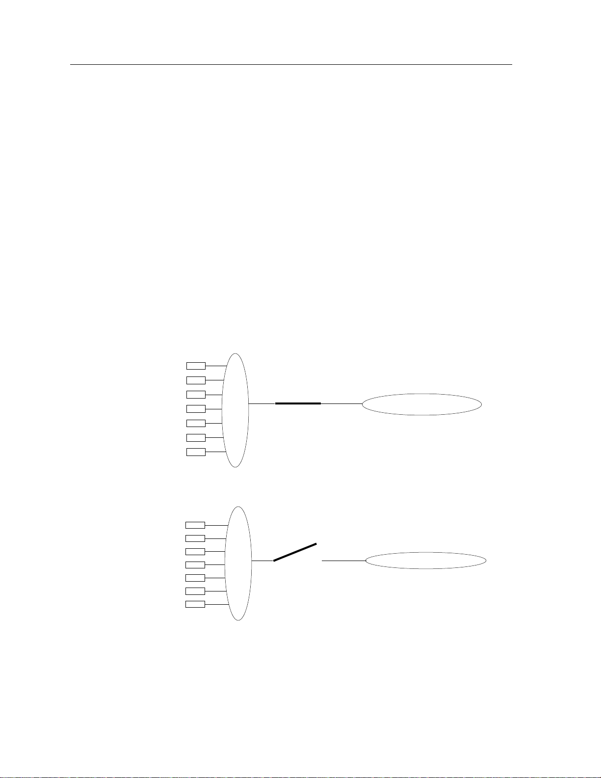
The terms INSERT and BYPASS refer to relays that are located on the module.
INSERT causes a relay to connect the module’s front panel ports to the selected
ring. BYPASS causes a relay to disconnect the module’s front panel ports from the
selected ring.
INSERT:
Front
Panel
Ports
BYPASS:
Front
Panel
Ports
Relay
Relay
FNB Ring
FNB Ring
The FNB Resource Configuration Screen lists all possible connections a module
can support on the FNB, displays the current connection, and allows you to
change the connection. Table 2 lists and describes the FDDI Connections from
which you can select.
2
Page 5

9F120-08 / 9F122-12 / 9F125-08 Module Specific Information
Table 2. 9F12x-xx MicroLAN Module FNB Resource Configuration Codes
Configuration
ID
FDDI Connections Description
1 FNB 1 Pri. (MAC) Byp. ,
FNB 2 Pri. (No MAC) Byp.
2 FNB 1 Pri. (MAC) Byp. ,
FNB 2 Pri. (No MAC) Ins.
3 FNB 1 Pri. (MAC) Ins. ,
FNB 2 Pri. (No MAC) Byp.
4 FNB 1 Pri. (MAC) Ins. ,
FNB 2 Pri. (No MAC) Ins.
The module is attached, but not inserted, to
the primary ring on the FNB-1. The module is
attached, but not inserted, to the primary ring
on the FNB-2. The MAC resides on FNB-1.
The module is attached to the FNB-1 primary
ring and the FNB-2 primary ring. The switch
that inserts the module into the FNB-1 is
turned off. The switch that inserts the module
into the FNB-2 is turned on. The MAC resides
on FNB-1.
The module is attached to the FNB-1 primary
ring and the FNB-2 primary ring. The switch
that inserts the module into the FNB-1 is
turned on. The switch that inserts the module
into the FNB-2 is turned off. The MAC resides
on FNB-1.
The module is attached to the FNB-1 primary
ring and the FNB-2 primary ring. The switch
that inserts the module into the FNB-1 is
turned on. The switch that inserts the module
into the FNB-2 is turned on. The MAC resides
on FNB-1.
5 FNB 1 Pri. (No MAC) Byp. ,
FNB 2 Pri. (MAC) Byp.
6 FNB 1 Pri. (No MAC) Byp. ,
FNB 2 Pri. (MAC) Ins.
The module is attached to the FNB-1 primary
ring and the FNB-2 primary ring. The switch
that inserts the module into the FNB-1 is
turned off. The switch that inserts the module
into the FNB-2 is turned off. The MAC resides
on FNB-2.
The module is attached to the FNB-1 primary
ring and the FNB-2 primary ring. The switch
that inserts the module into the FNB-1 is
turned off. The switch that inserts the module
into the FNB-2 is turned on. The MAC resides
on FNB-2.
3
Page 6

9F120-08 / 9F122-12 / 9F125-08 Module Specific Information
Table 2. 9F12x-xx MicroLAN Module FNB Resource Configuration Codes (Continued)
Configuration
ID
FDDI Connections Description
7 FNB 1 Pri. (No MAC) Ins. ,
FNB 2 Pri. (MAC) Byp.
8 FNB 1 Pri. (No MAC) Ins. ,
FNB 2 Pri. (MAC) Ins.
9 FNB 1 Pri. (MAC) Byp. ,
FNB 2 Sec. (No MAC) Byp.
10 FNB 1 Pri. (MAC) Byp. ,
FNB 2 Sec. (No MAC) Ins.
The module is attached to the FNB-1 primary
ring and the FNB-2 primary ring. The switch
that inserts the module into the FNB-1 is
turned on. The switch that inserts the module
into the FNB-2 is turned off. The MAC resides
on FNB-2.
The module is attached to the FNB-1 primary
ring and the FNB-2 primary ring. The switch
that inserts the module into the FNB-1 is
turned on. The switch that inserts the module
into the FNB-2 is turned on. The MAC resides
on FNB-2.
The module is attached to the FNB-1 primary
ring and the FNB-2 secondary ring. The
switch that inserts the module into the FNB-1
is turned off. The switch that inserts the
module into the FNB-2 is turned off. The
MAC resides on FNB-1.
The module is attached to the FNB-1 primary
ring and the FNB-2 secondary ring. The
switch that inserts the module into the FNB-1
is turned off. The switch that inserts the
module into the FNB-2 is turned on. The MAC
resides on FNB-1.
The module is attached to the FNB-1 primary
ring and the FNB-2 secondary ring. The
11 FNB 1 Pri. (MAC) Ins. ,
FNB 2 Sec. (No MAC) Byp.
switch that inserts the module into the FNB-1
is turned on. The switch that inserts the
module into the FNB-2 is turned off. The
MAC resides on FNB-1.
The module is attached to the FNB-1 primary
ring and the FNB-2 secondary ring. The
12 FNB 1 Pri. (MAC) Ins. ,
FNB 2 Sec. (No MAC) Ins.
switch that inserts the module into the FNB-1
is turned on. The switch that inserts the
module into the FNB-2 is turned on. The MAC
resides on FNB-1.
4
Page 7

9F120-08 / 9F122-12 / 9F125-08 Module Specific Information
Table 2. 9F12x-xx MicroLAN Module FNB Resource Configuration Codes (Continued)
Configuration
ID
FDDI Connections Description
13 FNB 1 Pri. (No MAC) Byp. ,
FNB 2 Sec. (MAC) Byp.
14 FNB 1 Pri. (No MAC) Byp. ,
FNB 2 Sec. (MAC) Ins.
15 FNB 1 Pri. (No MAC) Ins. ,
FNB 2 Sec. (MAC) Byp.
16 FNB 1 Pri. (No MAC) Ins. ,
FNB 2 Sec. (MAC) Ins.
The module is attached to the FNB-1 primary
ring and the FNB-2 secondary ring. The
switch that inserts the module into the FNB-1
is turned off. The switch that inserts the
module into the FNB-2 is turned off. The
MAC resides on FNB-2.
The module is attached to the FNB-1 primary
ring and the FNB-2 secondary ring. The
switch that inserts the module into the FNB-1
is turned off. The switch that inserts the
module into the FNB-2 is turned on. The MAC
resides on FNB-2.
The module is attached to the FNB-1 primary
ring and the FNB-2 secondary ring. The
switch that inserts the module into the FNB-1
is turned on. The switch that inserts the
module into the FNB-2 is turned off. The
MAC resides on FNB-2.
The module is attached to the FNB-1 primary
ring and the FNB-2 secondary ring. The
switch that inserts the module into the FNB-1
is turned on. The switch that inserts the
module into the FNB-2 is turned on. The MAC
resides on FNB-2.
17 FNB 1 Sec. (MAC) Byp. ,
FNB 2 Pri. (No MAC) Byp.
18 FNB 1 Sec. (MAC) Byp. ,
FNB 2 Pri. (No MAC) Ins.
The module is attached to the FNB-1
secondary ring and the FNB-2 primary ring.
The switch that inserts the module into the
FNB-1 is turned off. The switch that inserts the
module into the FNB-2 is turned off. The
MAC resides on FNB-1.
The module is attached to the FNB-1
secondary ring and the FNB-2 primary ring.
The switch that inserts the module into the
FNB-1 is turned off. The switch that inserts the
module into the FNB-2 is turned on. The MAC
resides on FNB-1.
5
Page 8

9F120-08 / 9F122-12 / 9F125-08 Module Specific Information
Table 2. 9F12x-xx MicroLAN Module FNB Resource Configuration Codes (Continued)
Configuration
ID
FDDI Connections Description
19 FNB 1 Sec. (MAC) Ins. ,
FNB 2 Pri. (No MAC) Byp.
20 FNB 1 Sec. (MAC) Ins. ,
FNB 2 Pri. (No MAC) Ins.
21 FNB 1 Sec. (No MAC) Byp. ,
FNB 2 Pri. (MAC) Byp.
22 FNB 1 Sec. (No MAC) Byp. ,
FNB 2 Pri. (MAC) Ins.
The module is attached to the FNB-1
secondary ring and the FNB-2 primary ring.
The switch that inserts the module into the
FNB-1 is turned on. The switch that inserts the
module into the FNB-2 is turned off. The
MAC resides on FNB-1.
The module is attached to the FNB-1
secondary ring and the FNB-2 primary ring.
The switch that inserts the module into the
FNB-1 is turned on. The switch that inserts the
module into the FNB-2 is turned on. The MAC
resides on FNB-1.
The module is attached to the FNB-1
secondary ring and the FNB-2 primary ring.
The switch that inserts the module into the
FNB-1 is turned off. The switch that inserts the
module into the FNB-2 is turned off. The
MAC resides on FNB-2.
The module is attached to the FNB-1
secondary ring and the FNB-2 primary ring.
The switch that inserts the module into the
FNB-1 is turned off. The switch that inserts the
module into the FNB-2 is turned on. The MAC
resides on FNB-2.
The module is attached to the FNB-1
secondary ring and the FNB-2 primary ring.
23 FNB 1 Sec. (No MAC) Ins. ,
FNB 2 Pri. (MAC) Byp.
The switch that inserts the module into the
FNB-1 is turned on. The switch that inserts the
module into the FNB-2 is turned off. The
MAC resides on FNB-2.
The module is attached to the FNB-1
secondary ring and the FNB-2 primary ring.
24 FNB 1 Sec. (No MAC) Ins. ,
FNB 2 Pri. (MAC) Ins.
The switch that inserts the module into the
FNB-1 is turned on. The switch that inserts the
module into the FNB-2 is turned on. The MAC
resides on FNB-2.
6
Page 9

9F120-08 / 9F122-12 / 9F125-08 Module Specific Information
Table 2. 9F12x-xx MicroLAN Module FNB Resource Configuration Codes (Continued)
Configuration
ID
FDDI Connections Description
25 FNB 1 Sec. (MAC) Byp. ,
FNB 2 Sec. (No MAC) Byp.
26 FNB 1 Sec. (MAC) Byp. ,
FNB 2 Sec. (No MAC) Ins.
27 FNB 1 Sec. (MAC) Ins. ,
FNB 2 Sec. (No MAC) Byp.
28 FNB 1 Sec. (MAC) Ins. ,
FNB 2 Sec. (No MAC) Ins.
The module is attached to the FNB-1
secondary ring and the FNB-2 secondary ring.
The switch that inserts the module into the
FNB-1 is turned off. The switch that inserts the
module into the FNB-2 is turned off. The
MAC resides on FNB-1.
The module is attached to the FNB-1
secondary ring and the FNB-2 secondary ring.
The switch that inserts the module into the
FNB-1 is turned off. The switch that inserts the
module into the FNB-2 is turned on. The MAC
resides on FNB-1.
The module is attached to the FNB-1
secondary ring and the FNB-2 secondary ring.
The switch that inserts the module into the
FNB-1 is turned on. The switch that inserts the
module into the FNB-2 is turned off. The
MAC resides on FNB-1.
The module is attached to the FNB-1
secondary ring and the FNB-2 secondary ring.
The switch that inserts the module into the
FNB-1 is turned on. The switch that inserts the
module into the FNB-2 is turned on. The MAC
resides on FNB-1.
29 FNB 1 Sec. (No MAC) Byp. ,
FNB 2 Sec. (MAC) Byp.
30 FNB 1 Sec. (No MAC) Byp. ,
FNB 2 Sec. (MAC) Ins.
The module is attached to the FNB-1
secondary ring and the FNB-2 secondary ring.
The switch that inserts the module into the
FNB-1 is turned off. The switch that inserts the
module into the FNB-2 is turned off. The
MAC resides on FNB-2.
The module is attached to the FNB-1
secondary ring and the FNB-2 secondary ring.
The switch that inserts the module into the
FNB-1 is turned off. The switch that inserts the
module into the FNB-2 is turned on. The MAC
resides on FNB-2.
7
Page 10

9F120-08 / 9F122-12 / 9F125-08 Module Specific Information
Table 2. 9F12x-xx MicroLAN Module FNB Resource Configuration Codes (Continued)
Configuration
ID
FDDI Connections Description
31 FNB 1 Sec. (No MAC) Ins. ,
FNB 2 Sec. (MAC) Byp.
32 FNB 1 Sec. (No MAC) Ins. ,
FNB 2 Sec. (MAC) Ins.
The module is attached to the FNB-1
secondary ring and the FNB-2 secondary ring.
The switch that inserts the module into the
FNB-1 is turned on. The switch that inserts the
module into the FNB-2 is turned off. The
MAC resides on FNB-2.
The module is attached to the FNB-1
secondary ring and the FNB-2 secondary ring.
The switch that inserts the module into the
FNB-1 is turned on. The switch that inserts the
module into the FNB-2 is turned on. The MAC
resides on FNB-2.
8
Page 11

9F120-08 / 9F122-12 / 9F125-08 Module Specific Information
Module Specific Configuration Screen
In the FNB Resource Configuration Screen, you determine which of the two FNB
rings contains the MAC. The
Screen allows you to assign one of the two FNB rings (either the ring that contains
the MAC or the ring that does not contain the MAC) to each of the module’s Mports. The default ring that is assigned to each of the module’s M-ports is the ring
that contains the MAC.
SmartSwitch 9000 LOCAL MANAGEMENT
Module Specific Configuration
Module Name: 9F120-08 Firmware Revision: 01.01.01
Slot Number: 12 BOOTPROM Revision: 00.00.04
FNB 1 Pri. (MAC) Ins. , FNB 2 Pri. (No MAC) Ins.
9F120 MicroLAN
Module Specific Configuration
PORT# PATH CONNECT STATE
1 [MAC-1] CON
2 [MAC-1] CON
3 [MAC-1] CON
4 [MAC-1] CON
5 [MAC-1] CON
6 [MAC-1] CON
7 [MAC-1] CON
8 [MAC-1] CON
SAVE RETURN
Figure 1. 9F120 MicroLAN Module Specific Statistics Screen
To assign an FNB ring to a module’s M-port:
1. Use the arrow keys to highlight the PATH field next to the desired port.
2. Press the SPACE BAR to toggle to the desired ring (either MAC-1 or No
MAC).
3. Press the Return key. Repeat steps 1-3 to assign an FNB ring to other M-ports.
4. Use the arrow keys to highlight SAVE at the bottom of the screen and press
the Return key. When the message “SAVED OK” appears, the edits you have
made are saved. If you exit without saving, the message “NOT SAVED -PRESS SAVE TO KEEP CHANGES” appears. If you proceed to exit without
saving, your edits will be lost.
5. Use the arrow keys to highlight RETURN and press the Return key.
9
Page 12

9F120-08 / 9F122-12 / 9F125-08 Module Specific Information
10
 Loading...