

Cabletron Systems SmartSwitch 9500, 9A600, SmartSwitch 9500 9A600 Hardware And Installation Manual
Page 1

SmartSwitch 9500
9A600 ATM Module
Hardware and Installation Guide
9032703
Page 2

Page 3

Notice
Cabletron Systems reserves the right to make changes in speciÞcations and other information
contained in this document without prior notice. The reader should in all cases consult Cabletron
Systems to determine whether any such changes have been made.
The hardware, Þrmware, or software described in this manual is subject to change without notice.
IN NO EVENT SHALL CABLETRON SYSTEMS BE LIABLE FOR ANY INCIDENTAL, INDIRECT,
SPECIAL, OR CONSEQUENTIAL DAMAGES WHATSOEVER (INCLUDING BUT NOT LIMITED
TO LOST PROFITS) ARISING OUT OF OR RELATED TO THIS MANUAL OR THE INFORMATION
CONTAINED IN IT, EVEN IF CABLETRON SYSTEMS HAS BEEN ADVISED OF, KNOWN, OR
SHOULD HAVE KNOWN, THE POSSIBILITY OF SUCH DAMAGES.
© August 1998 by:
Cabletron Systems, Inc.
35 Industrial Way
Rochester, NH 03867
All Rights Reserved
Printed in the United States of America
Order Number: 9032703
Cabletron Systems and LANVIEW are registered trademarks of Cabletron Systems, Inc.
VT100 is a registered trademark of Digital Equipment Corporation.
Ethernet is a trademark of Xerox Corporation.
i
Page 4

Notice
FCC Notice
This device complies with Part 15 of the FCC rules. Operation is subject to the following two
conditions: (1) this device may not cause harmful interference, and (2) this device must accept any
interference received, including interference that may cause undesired operation.
NOTE: This equipment has been tested and found to comply with the limits for a Class A digital
device, pursuant to Part 15 of the FCC rules. These limits are designed to provide reasonable
protection against harmful interference when the equipment is operated in a commercial environment.
This equipment uses, generates, and can radiate radio frequency energy and if not installed in
accordance with the operatorÕs manual, may cause harmful interference to radio communications.
Operation of this equipment in a residential area is likely to cause interference in which case the user
will be required to correct the interference at his own expense.
WARNING: Changes or modiÞcations made to this device which are not expressly approved by the
party responsible for compliance could void the userÕs authority to operate the equipment.
VCCI Notice
This is a Class A product based on the standard of the Voluntary Control Council for Interference by
Information Technology Equipment (VCCI). If this equipment is used in a domestic environment,
radio disturbance may arise. When such trouble occurs, the user may be required to take corrective
actions.
Industry Canada Notice
This digital apparatus does not exceed the Class A limits for radio noise emissions from digital
apparatus set out in the Radio Interference Regulations of the Canadian Department of
Communications.
Le prŽsent appareil numŽrique nÕŽmet pas de bruits radioŽlectriques dŽpassant les limites applicables
aux appareils numŽriques de la class A prescrites dans le R•glement sur le brouillage radioŽlectrique
ŽdictŽ par le minist•re des Communications du Canada.
ii
Page 5

Notice
Declaration of Conformity
Addendum
Application of Council Directive(s):
ManufacturerÕs Name:
ManufacturerÕs Address:
European Representative Name:
European Representative Address:
Conformance to Directive(s)/Product Standards:
Equipment Type/Environment:
We the undersigned, hereby declare, under our sole responsibility, that the equipment packaged with
this notice conforms to the above directives.
89/336/EEC
73/23/EEC
Cabletron Systems, Inc.
35 Industrial Way
PO Box 5005
Rochester, NH 03867
Mr. J. Solari
Cabletron Systems Limited
Nexus House, Newbury Business Park
London Road, Newbury
Berkshire RG13 2PZ, England
EC Directive 89/336/EEC
EC Directive 73/23/EEC
EN 55022
EN 50082-1
EN 60950
Networking Equipment, for use in a
Commercial or Light
Industrial Environment.
Mr. Ronald Fotino Mr. J. Solari
____________________________________________________ ______________________________________________________
Full Name Full Name
Principal Compliance Engineer Managing Director - E.M.E.A.
____________________________________________________ ______________________________________________________
Title Title
Rochester, NH, USA Newbury, Berkshire, England
____________________________________________________ ______________________________________________________
Location Location
iii
Page 6

Notice
iv
Page 7

Chapter 1 Introduction
Document Objectives.................................................................................................... 1-1
Overview........................................................................................................................ 1-2
Features........................................................................................................................... 1-4
Processor .................................................................................................................1-4
Cabletron Systems ASICs ..................................................................................... 1-4
System Management ............................................................................................. 1-4
Connectivity............................................................................................................ 1-4
Early Packet Discard (EPD) and Partial Packet Discard (PPD)....................... 1-5
LANVIEW LEDs .................................................................................................... 1-5
Related Manuals............................................................................................................ 1-5
Getting Help .................................................................................................................. 1-6
Contents
Chapter 2 Installing the 9A600 Module
The Reset Switch ...........................................................................................................2-3
The Module Card DIP Switch ..................................................................................... 2-4
Installing an ANIM....................................................................................................... 2-5
Chapter 3 Operation
ATM Cell TrafÞc Flow in the 9A600 ........................................................................... 3-2
Cabletron Systems ASICs ..................................................................................... 3-2
i960HD Processor................................................................................................... 3-2
System Management Buses .........................................................................................3-3
SMB-1 Bus ............................................................................................................... 3-3
SMB-10 Bus ............................................................................................................. 3-3
System Diagnostic Controller...................................................................................... 3-4
DC/DC Converter ........................................................................................................3-4
v
Page 8

Contents
Chapter 4 LANVIEW LEDs
ANIM LEDs ............................................................................................................4-3
Chapter 5 General Specifications
Operating SpeciÞcations ..............................................................................................5-1
Environmental Requirements ..............................................................................5-1
Regulatory Compliance.........................................................................................5-1
Service............................................................................................................................. 5-1
Physical...........................................................................................................................5-2
Device SpeciÞcations ....................................................................................................5-2
ANIM SpeciÞcations.....................................................................................................5-2
ANIM-21/3 ............................................................................................................. 5-3
ANIM-29/3 ............................................................................................................. 5-4
ANIM-29/3LR ........................................................................................................ 5-5
ANIM-31/2 ............................................................................................................. 5-6
ANIM-39/2 ............................................................................................................. 5-7
ANIM-39/2LR ........................................................................................................ 5-8
ANIM-67/2 ............................................................................................................. 5-9
ANIM-77/2 ........................................................................................................... 5-10
ANIM-22/4 ........................................................................................................... 5-11
vi
Page 9

Introduction
Document Objectives
This document, the SmartSwitch 9500 9A600ATM Module Hardware and Installation
Guide , contains introductory, installation and speciÞcation information for the
support of the 9A600 SmartSwitch Module. Use this guide to learn about the
following topics:
Chapter 1
NOTE
¥ Overview of the 9A600
¥ Installing the 9A600 in the SmartSwitch 9500 chassis
¥ Installing ATM Network Interface Modules (ANIMs)
¥ Learning the hardware speciÞcations of the 9A600 and the available ANIMs
Prior to installing the 9A600, you should have a working knowledge of ATM
networking principles.
In this document, the Cabletron Systems SmartSwitch 9000 chassis is referred to
as the “SmartSwitch 9500 chassis” which indicates a SmartSwitch 9000 chassis
with one or more 9A600 modules installed.
The 9A600 may also be installed in a SmartSwitch 9000 chassis, which indicates
a chassis without a Cell Transfer Matrix (CTM) backplane.
1-1
Page 10

Introduction
Overview
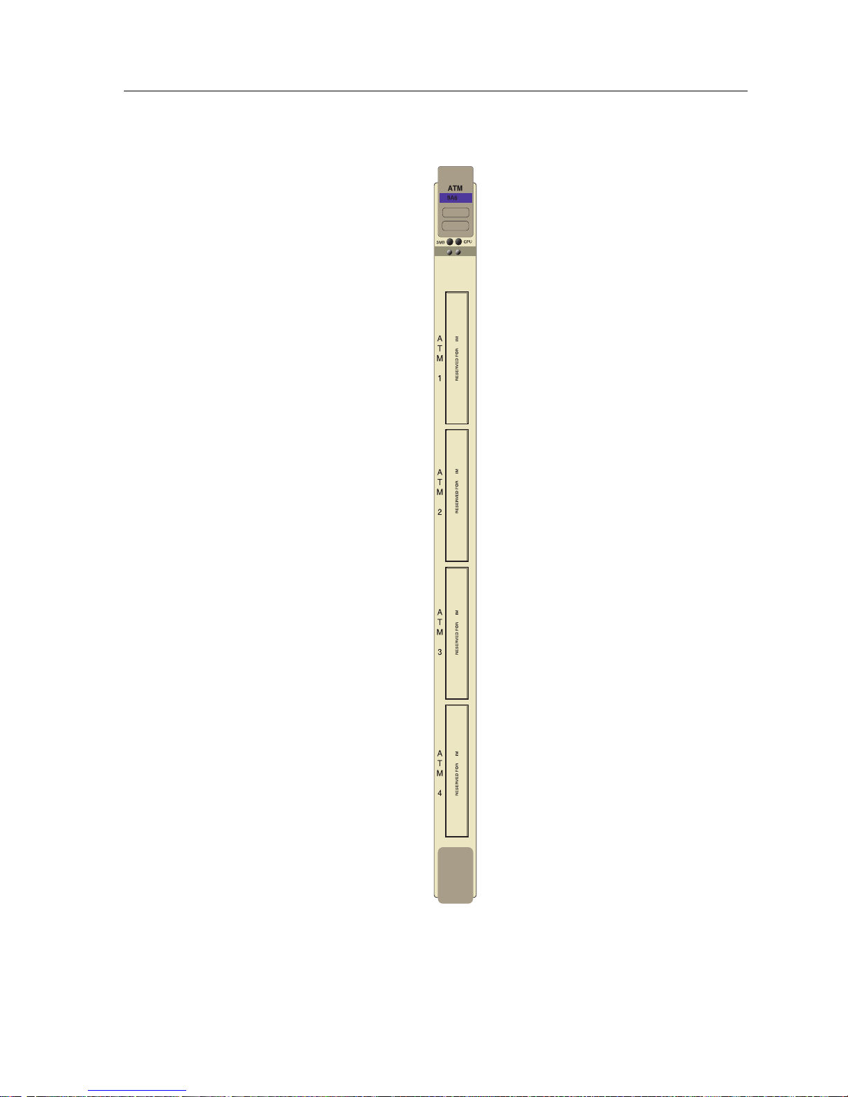
The 9A600 (shown in Figure 1-1) is a 5.4 Gbps, single slot module for the
SmartSwitch 9500 chassis. Up to four ATM Network Interface Modules (ANIMs)
of any type can be plugged into the 9A600 to provide front panel connectivity to
the network. Cabletron Systems ANIMs can support up to 622 Mbps of
bandwidth per port. The 9A600 switches data between the ANIMs that are
installed in the module.
Through its distributed switching architecture, the 9A600 allows all the modules
in the chassis to appear as a single entity, with a single IP address and a single
ATM address. The individual i960 processors are transparent to the network
manager and management applications. A fully loaded SmartSwitch 9500 chassis
appears as a single switch, with one IP address, and one ATM address.
The 9A600 is fully compatible with the following ATM Forum speciÞcations:
¥ Integrated Local Management Interface (ILMI) 4.0 for autoconÞguration.
¥ UNI v3.0 /3.1 and v4.0 for signalling.
¥ ATM Forum P-NNI 1.0 and IISP 3.0/3.1 routing speciÞcations for establishing
connections between ATM switches.
¥ IETF AToM MIB (RFC 1695) and AToM II MIB.
¥ LANE 1.0 for the management LAN Emulation Client.
1-2
Page 11
Overview
00
AN
AN
AN
AN
Figure 1-1. The 9A600
1-3
Page 12

Introduction
Features
The features of the 9A600 are described in the sections below:
Processor
The 9A600 is equipped with an advanced Intel i960 microprocessor. This
microprocessor provides signalling, SNMP management, and serves as the
in-band management LAN Emulation Client (LEC).
Cabletron Systems ASICs
The 9A600 contains four different Cabletron Systems designed ASICs that
provide a variety of switching services. For more information on these ASICs
refer to Chapter 3.
System Management
The 9A600 connects to the two System Management Buses (SMB-1 and SMB-10)
for module management. Management features include the following:
¥ Power and environmental status monitoring
¥ PNNI and ILMI conÞguration
¥ SmartSwitch 9500 chassis IP address assignment
¥ Ability to conÞgure the in-band management LAN Emulation Client
¥ SmartSwitch 9500 chassis SNMP community names and trap IP address
assignment
¥ Ability to access Local Management screens of any module installed in the
chassis
Connectivity
The 9A600 can be equipped with a variety of front panel interfaces called ATM
Network Interface Modules (ANIMs). ANIMs provide a variety of physical layer
cabling options, including the following:
¥ Unshielded Twisted Pair (UTP) using OC-3.
¥ Multimode Fiber Optic Cable (MMF) using OC-3 or OC-12.
¥ Single Mode Fiber Optic Cable (SMF) using OC-3 or OC-12.
¥ Coaxial Cable using DS-3.
ANIMs are also capable of handling varying amounts of bandwidth including
SONET OC3/SDH, and STS-3/STM-1 (155 Mbps), SONET OC12/SDH
(622 Mbps) and DS3 (45 Mbps).
1-4
Page 13

Related Manuals
Early Packet Discard (EPD) and Partial Packet Discard (PPD)
The 9A600 supports early and partial packet discard to help ensure that quality of
service parameters are met for all connections. EPD and PPD, in conjunction with
trafÞc policing, discard ATM cells that the end device would have to retransmit
(due to buffer overload, line loss, line bit errors, faulty cells etc.) thereby limiting
the amount of bad trafÞc present on the ATM network.
LANVIEW LEDs
The 9A600 uses LANVIEW, The Cabletron Systems built-in visual diagnostic and
status monitoring system. With LANVIEW LEDs, you can quickly identify the
device, port, and physical layer status at a glance.
Related Manuals
The manuals listed below should be used to supplement the procedures and
technical data contained in this manual.
9A656-04 and 9A600 ConÞguration Guide
SmartSwitch 9000 Installation Guide
SmartSwitch 9000 Operations Guide
SmartSwitch 9000 9C300-1 Environmental Module UserÕs Guide
SmartSwitch 9000 9C214-1 AC Power Supply UserÕs Guide
SmartSwitch 9000 Local Management UserÕs Guide
SmartSwitch 9000 6 9C106 Setup and Installation Guide
SmartSwitch 9000 6 Module Local Management UserÕs Guide
1-5
Page 14

Introduction
Getting Help
For additional support related to this device or document, contact the Cabletron Systems Global Call
Center:
Phone (603) 332-9400
Internet mail support@cabletron.com
FTP ftp://ftp.cabletron.com/
Login
Password
For additional information about Cabletron Systems or its products, visit the
World Wide Web site: http://www.cabletron.com/
To send comments or suggestions concerning this document, contact the
Cabletron Systems Technical Writing Department via the following
email address: TechWriting@cabletron.com
Make sure to include the document Part Number in the email message.
anonymous
your email address
Before calling the Cabletron Systems Global Call Center, have the following information ready:
• Your Cabletron Systems service contract number
• A description of the failure
• A description of any action(s) already taken to resolve the problem (e.g., changing mode switches,
rebooting the unit, etc.)
• The serial and revision numbers of all involved Cabletron Systems products in the network
• A description of your network environment (layout, cable type, etc.)
• Network load and frame size at the time of trouble (if known)
• The device history (i.e., have you returned the device before, is this a recurring problem, etc.)
• Any previous Return Material Authorization (RMA) numbers
1-6
Page 15

Installing the 9A600 Module
SmartSwitch 9500 modules can be installed in any of the slots that are available.
To install a module, proceed as follows:
Chapter 2
!
CAUTION
!
CAUTION
Observe all antistatic precautions when handling sensitive electronic equipment.
1. Remove the blank plate covering the slot in which the 9A600 will be installed.
All other slots must remain covered to ensure proper airßow and cooling.
(Save the blank plate in the event you need to remove the module.)
2. Unpack the 9A600 by carefully removing it from the shipping box. (Save the
box and packing materials in the event the module must be reshipped.)
3. Remove the 9A600 from the plastic bag. (Save the bag in the event the module
must be reshipped.) Observe all precautions to prevent damage from
Electrostatic Discharge (ESD).
4. Examine the 9A600 for damage. If any damage exists, DO NOT install the
module. Immediately contact the Cabletron Systems Global Call Center.
To prevent damaging the backplane connectors in the following step, take care
that the module slides in straight and properly engages the backplane connectors.
5. Install the 9A600 module in the chassis by aligning the module card between
the upper and lower metal slot guides of any available slot, sliding it into the
chassis, and locking down the top and bottom plastic tabs, as shown in Figure
2-1. Take care that the 9A600 slides in straight and properly engages the
backplane connectors.
The 9A600 may be removed from the chassis while it is operational, but a brief
system downtime will result. When the interface module is remo ved, the remaining
!
CAUTION
modules go through an initialization process to determine which interface module
will become the module that performs specific management functions.
2-1
Page 16

Installing the 9A600 Module
Plastic Locking Tab
00
Metal Back-Panel
AN
AN
AN
AN
Plastic Locking Tab
Circuit Card
Card Guides
Figure 2-1. Installing the 9A600
2-2
Page 17

The Reset Switch
Resetting the 9A600 will cause a brief period of system downtime. When the
interface module is reset, the remaining modules go through an initialization
!
CAUTION
process to determine which interface module will become the module that
performs specific management functions.
The Reset switch is located on the front panel, under the top plastic tab as shown
in Figure 2-2. It serves two functions:
¥ Pressing the Reset switch twice within three seconds causes the processor
(i960) to reset.
¥ Pressing and holding the switch on for three or more seconds causes the
module to shutdown. Pressing and holding the button again for three seconds
restarts the module.
The Reset Switch
SNMP management may be used to disable this switch to enhance module
security.
Reset Switch
Figure 2-2. The Reset Switch
9A600
2-3
Page 18

Installing the 9A600 Module
The Module Card DIP Switch
An eight position DIP switch is located on the module card as shown in
Figure 2-3. The functions of the switches are listed in Table 2-1.
Do not toggle Switch 8 unless you intend to reset the user configured passwords
to their factory default settings.
!
CAUTION
Do not toggle Switch 7 unless you intend to reset the user parameters to the
factory default settings. Refer to the 9A656-04 and 9A600 Configuration Guide
for instructions on the parameters that may be configured by the user via
Local/Remote Management.
Table 2-1. Function of the DIP Switch
Switch Function Description
When toggled, this switch clears user-entered
8
7
6
5 Reserved For Factory Use Only
4 Reserved For Factory Use Only
Clear
Password
Clear
NVRAM
Force BootP
Download
passwords stored in NVRAM, and restores the
default passwords. Once reset you can use the
defaults or enter new passwords.
The module uses NVRAM to store user
entered parameters such as IP addresses,
device name, etc. To reset these parameters to
the factory defaults, toggle this switch. Once
reset you can use the defaults or enter new
parameters which are stored in NVRAM when
the module is powered down, and remain
there until the switch is toggled again.
Toggling this switch after pulling the board
out of the SmartSwitch 9500, clears download
information from NVRAM and forces image
files to be downloaded from the station
connected to the EPIM on the Environmental
Module configured to act as that modulesÕ
B
OOT
P server.
3 Reserved For Factory Use Only
2 Reserved For Factory Use Only
1 Reserved For Factory Use Only
2-4
Page 19

Installing an ANIM
Figure 2-3 shows the location of the 4 motherboard connectors, and the 16
standoff screws for the ATM Network Interface Modules (ANIMs). Figure 2-3 also
shows the location of the Module Card DIP Switch.
ANIM Connectors (4)
i960 Processor
Installing an ANIM
Standoff Screws (16)
Figure 2-3. ANIM Connector Locations and Module DIP Switch Location
2031_04
DIP Switch
12345678
2-5
Page 20

Installing the 9A600 Module
The ANIM and 9A600 module are sensitive to static discharges. Use a grounding
strap and observe all static precautions during this procedure. Failure to do so
!
CAUTION
could damage the ANIM and the 9A600 module.
If you are installing ANIMs in more than one slot, remove the co v er plates from all
NOTE
the associated slot openings.
A Phillips Head screwdriver is needed to install the ANIMs.
The 9A600 module is shipped without ANIMs. To install the ANIMs proceed as
follows:
1. Remove the module if it is installed in the SmartSwitch 9500 chassis. To
remove a module, release (rotate outward) the top and bottom plastic locking
tabs, then slide the module out of the chassis.
2. Refer to Figure 2-4. Remove the two screws fastening the coverplate to the
front standoffs where the ANIM is to be installed. Save the screws.
3. Lift and remove the coverplate from the top of the front standoffs.
Coverplate
RESERVED FOR ANIM
4. Refer to Figure 2-5. Hold the ANIM by the provided cutouts on the board of
the ANIM.
2-6
Front
Standoffs
Figure 2-4. Removing the Coverplate
Page 21

!
CAUTION
Installing an ANIM
When installing or removing an ANIM make sure to always use the cut
outs on the board to handle the ANIM. See Figure 2-6 for the location of
the cutouts.
When connecting the ANIM pins to the motherboard connector take extra
precaution that the pins do not enter the connector at an angle as this will
damage both the ANIM and the motherboard connector.
5. Press straight down Þrmly on the ANIM until the pins slide all the way into
the motherboard connector. Ensure that the ANIM seats ßush on the
standoffs.
6. Secure the ANIM with the two screws saved in step 2 and the two screws
supplied with each ANIM.
7. If there is more than one ANIM to install, repeat steps 2 through 6 to install
each one.
Standoff
Cut Out
Figure 2-5. Installing an ANIM
Module
Cut Out
Module
Connector
Motherboard
Connector
Motherboard
Standoffs
2-7
Page 22

Installing the 9A600 Module
2-8
Page 23

Operation
The 9A600 provides switching between the front panel interfaces (ANIMs). Figure
3-1 shows the trafÞc ßow of ATM cells in the 9A600. The following sections brießy
describe the functions of the i960 Processor, the ASICs, and how they relate to
ATM cell trafÞc ßow.
Chapter 3
Phycsical
Connection
to Network
ATM CELLS
Shared DRAM
Provides management and
configuration interface for
the 9A600
Separates/assembles
cell header data
CELL HEADER INFORMATION
UTOPIA
ASICs
CPU
i960
To SMB-1 & 10
To Z-80 Processor
Translates headers and provides
routing information to move ATM
cells out of the TDM
TDM
ASIC
ATM CELLS
Provides translation between
the I/O ATM bidirectional data
and the TDM
SAR
Segments and reassembles
data into ATM cells
Queue
ASICs
SARI
ASIC
ROUTING INFORMATION
DATA
TDM Bus
DATA
Figure 3-1. 9A600 Block Diagram
3-1
Page 24

Operation
ATM Cell Traffic Flow in the 9A600
The 9A600 SmartSwitch utilizes several innovative features that result in a
completely redundant, fault-tolerant design. The most important hardware facets
of the 9A600 features are the Cabletron Systems ASICs, and the i960 HD RISC
Processor.
Cabletron Systems ASICs
The 9A600 SmartSwitch utilizes four separate Cabletron Systems designed ASICs
to perform switching functions. Refer to Figure 3-1 to see how these four ASICs
work together to provide proper trafÞc ßow. The deÞnitions for these ASICs are as
follows:
Queue ASIC
The 9A600 has four Queue ASICs installed on the motherboard. These ASICs
support 16 priority queues each. The Queue ASICs support all classes of ATM
service including Constant Bit Rate (CBR), Variable Bit Rate (VBR), Available Bit
Rate (ABR) and UnspeciÞed Bit Rate (UBR). The Queue ASICs also manage all cell
transfers to the Utopia ASICs, using a weighted round-robin algorithm.
TDM (Time Division Multiplexer) ASIC
The TDM ASIC is the central switching engine of the 9A600. The TDM ASIC
maintains the connection table, gathers statistics, and provides Usage Parameter
Control (UPC) policing. The TDM ASIC supports up to 128k virtual connections.
SARI (Segmentation and Reassembly Interface) ASIC
The SARI ASIC is the interface that controls the data ßow between the TDM Bus
and the i960 Host Processor. The SARI ASIC has a 768-cell queue and provides the
trafÞc management features of the 9A600.
Utopia (Universal Test and Operation Physical Interface) ASICs
The 9A600 has four Utopia ASICs whose role is to process ATM cells from the
ANIMs to the TDM Bus, and vice versa. In addition, the Utopia ASICs are
responsible for performing path lookups and outbound header translation.
i960HD Processor
The i960HD processor, working with the four types of ASICs deÞned earlier, is
responsible for distributed management functions, signalling, SNMP
management and serving as the in-band management LAN Emulation Client
(LEC) for the module. The i960 also supports out-of-band management interfaces.
3-2
Page 25

System Management Buses
There are two management channels within the SmartSwitch 9500 system:
¥ SMB-1
¥ SMB-10
These buses provide out-of-band management and inter-module management
communication.
SMB-1 Bus
The SMB-1 is a 1 Mbps management bus located within the SmartSwitch 9500
chassis. This bus is used by all diagnostic controllers in the system, including the
following:
¥ Connectivity modules
¥ Power supply modules
¥ The environmental module
The SMB-1 transports inter-chassis information between system components,
such as power and environmental information, as well as diagnostic messages.
Periodic loop-back tests are performed by all modules that share this bus to
ensure the validity of SMB-1. In the event a failure is detected on SMB-1, the SMB10 may be used as an alternate communication channel.
System Management Buses
SMB-10 Bus
The SMB-10 is a 10 Mbps management bus located within the SmartSwitch 9500
chassis, which is also used for inter-chassis communication of modules, as well as
serving as an out-of-band management channel into the SmartSwitch 9500. The
SMB-10 is externalized from the chassis via an optional Ethernet Port Interface
Module (EPIM) located on the front of the environmental module. Through an
EPIM connection, full SNMP management of the SmartSwitch 9500 is available
out-of-band from user data. Modules that share the SMB-10 bus periodically send
out loopback packets to ensure the validity of the SMB-10. In the event a fault is
detected on the SMB-10, the SMB-1 can be used as an alternate communication
channel by the modules.
3-3
Page 26

Operation
System Diagnostic Controller
This diagnostic controller is composed of a Z-80 microprocessor and its
supporting logic. The diagnostic controller performs the following:
¥ Controls the power-up sequencing of modules
¥ Monitors the 9A600 input and output power parameters
¥ Keeps watch over the main host processor
¥ Monitors the temperature
¥ Controls the SMB LANVIEW diagnostic LED
Although the diagnostic controller and the main host processor can operate
independently of each other if needed, they exchange information about each
otherÕs status and overall module condition. The information gathered by the
diagnostic controller is available to the network manager via Local/Remote
Management and the LCD located on the environmental module. The 9A600 has
been designed so that in the event of a diagnostic controller fault, the modules
continue to function.
DC/DC Converter
The DC/DC converter converts the 48 Vdc on the system power bus to the
necessary operating voltages for its host network services module. The diagnostic
controller controls the operation of the dc/dc converter.
3-4
Page 27

LANVIEW LEDs
The front panel LANVIEW LEDs indicate the status of the module and may be
used as an aid in troubleshooting. Shown in Figure 4-1 are the LANVIEW LEDs of
the 9A600 module. Refer to Table 4-1 for the full deÞnitions of 9A600 LED states.
SMB Status
Chapter 4
9A600
System Status
2031_09
Figure 4-1. 9A600 LANVIEW LEDs
4-1
Page 28

LANVIEW LEDs
LED LED Color State DeÞnition
Table 4-1. SMB and CPU LEDs
Green Functional Fully operational
SMB
CPU
Amber Fault
No database synchronization with the
Environmental Module or SMB.
Off Power off Module powered off
Amber/Green Booting LED blinks amber and green while booting
Red (Flashing) Failed Fatal error has occurred
Off Power off Module powered off
4-2
Page 29

ANIM LEDs
The front panel LANVIEW LEDs indicate the status of the ANIM and may be
used as an aid in troubleshooting. Shown in Figure 4-2 are the LANVIEW LEDs of
all ANIMs. Although there are several types of ANIMs, all share the same
LANVIEW LEDs. Refer to Table 4-2 for the full deÞnitions of ANIM LED states.
ATM Link
ATM Status
2031_10
Figure 4-2. ANIM LEDs
Table 4-2. ANIM LEDs
LED LED Color Status
Green Link
LNK
Off No Link
Green Port Enabled and OK
STS
Amber Standby
Red Port Enabled and Error
4-3
Page 30

LANVIEW LEDs
4-4
Page 31

General Specifications
The speciÞcations for the 9A600 are detailed in the sections that follow.
Operating Specifications
Environmental Requirements
Operating Temperature: 5¡C to 40¡C (41¡F to 104¡F)
Storage Temperature: -30¡C to 73¡C (-22¡F to 164¡F)
Operating Relative Humidity: 5% to 90% (non-condensing)
Chapter 5
Regulatory Compliance
Safety
This equipment meets the safety requirements of UL 1950, CSA C22.2 No. 950,
EN 60950, IEC 950 and 73/23/EEC.
Electromagnetic Compatibility
This equipment meets the requirements of FCC Part 15, EN 55022,
VCCI V-3, CSA C108.8, EN 50082-1, AS/NZS 3548 and 89/336/EEC.
Service
MTBF MHBK+217E >200,000 hrs.
MTTR <0.5 hr.
5-1
Page 32

General Specifications
Physical
Dimensions
35.0 D x 44.0 H x 3.0 W centimeters
(13.8 D x 17.4 H x 1.2 W inches)
Weight
Unit: 1.36 kg. (3lb)
Shipping: 1.81 kg. (4lb)
Device Specifications
Processor
Intel i960HD RISC processor control
Dynamic Random Access Memory (DRAM)
64 MB
FLASH Memory
8 MB
ANIM Specifications
The 9A600 uses ATM Network Interface Modules (ANIMs) to provide front panel
cable connections. The ANIMs should be installed by qualiÞed personnel. Refer to
the section in Chapter 2 entitled Installing an ANIM for full instructions on the
installation process.
5-2
Page 33

ANIM-21/3
ANIM Specifications
The ANIM-21/3 provides a multimode Þber connection using a Duplex SC
connector and a line rate of 155.52 Mbps. The speciÞcations for the ANIM-21/3
are listed in Table 5-1.
Table 5-1 .ANIM-21/3 Specifications
Parameter SpeciÞcation
Number of Interfaces 3
Line Rate 155.52 Mbps
Interface Type Duplex SC
Media Type Multimode Fiber
Frame Type SONET/SDH
Typical Range 2 km
Loss Budget
TX -17 db to -12 db
RX -27 db to -12 db
2031_11
Figure 5-1. ANIM-21/3
5-3
Page 34

General Specifications
ANIM-29/3
The ANIM-29/3 provides a single mode Þber connection using a Duplex SC
connector with a line rate of 155.52 Mbps. The speciÞcations for the ANIM-29/3
are listed in Table 5-2.
Table 5-2 .ANIM-29/3 Specifications
Parameter SpeciÞcation
Number of Interfaces 3
Line Rate 155.52 Mbps
Interface Type Duplex SC
Media Type Single mode Fiber
Frame Type SONET/SDH
Typical Range 15 km
Loss Budget
TX -15 db to -8 db
RX -31 db to -8 db
2031_11
Figure 5-2. ANIM-29/3
5-4
Page 35

ANIM-29/3LR
ANIM Specifications
The ANIM-29/3LR provides a single mode Þber connection using a Duplex SC
connector with a line rate of 155.52 Mbps. The speciÞcations for the ANIM29/3LR are listed in Table 5-3.
Table 5-3 .ANIM-29/3LR Specifications
Parameter SpeciÞcation
Number of Interfaces 3
Line Rate 155.52 Mbps
Interface Type Duplex SC
Media Type Single mode Fiber
Frame Type SONET/SDH
Typical Range 60 km
Loss Budget
TX -15 db to -8 db
RX -31 db to -8 db
2031_11
Figure 5-3. ANIM-29/3LR
5-5
Page 36

General Specifications
ANIM-31/2
The ANIM-31/2 provides a multimode Þber connection using a Duplex SC
connector with a line rate of 622 Mbps. The speciÞcations for the ANIM-31/2 are
listed in Table 5-4.
Table 5-4 .ANIM-31/2 Specifications
Parameter SpeciÞcation
Number of Interfaces 2
Line Rate 622 Mbps
Interface Type Duplex SC
Media Type Multimode Fiber
Frame Type SONET/SDH
Typical Range 2km
Loss Budget
TX -19 db to -14 db
RX -26 db to -14 db
2031_12
Figure 5-4. ANIM 31/2
5-6
Page 37

ANIM-39/2
ANIM Specifications
The ANIM-39/2 provides a single mode Þber connection using a Duplex SC
connector with a line rate of 622 Mbps. The speciÞcations for the ANIM-39/2 are
listed in Table 5-5.
Table 5-5 .ANIM-39/2 Specifications
Parameter SpeciÞcation
Number of Interfaces 2
Line Rate 622 Mbps
Interface Type Duplex SC
Media Type Single mode Fiber
Frame Type SONET/SDH
Typical Range 15 km
Loss Budget
TX -15 db to -8 db
RX -28 db to -7 db
2031_12
Figure 5-5. ANIM 39/2
5-7
Page 38

General Specifications
ANIM-39/2LR
The ANIM-39/2LR provides a single mode Þber connection using a Duplex SC
connector with a line rate of 622 Mbps. The speciÞcations for the ANIM-39/2LR
are listed in Table 5-5.
Table 5-6 .ANIM-39/2LR Specifications
Parameter SpeciÞcation
Number of Interfaces 2
Line Rate 622 Mbps
Interface Type Duplex SC
Media Type Single mode Fiber
Frame Type SONET/SDH
Typical Range 60 km
Loss Budget
TX -15 db to -8 db
RX -28 db to -7 db
2031_12
5-8
Figure 5-6. ANIM 39/2LR
Page 39

ANIM-67/2
ANIM Specifications
The ANIM-67/2 provides a coaxial cable connection using BNC connectors with a
line rate of 45 Mbps. The speciÞcations for the ANIM-67/2 are listed in Table 5-7.
Table 5-7 .ANIM-67/2 Specifications
Parameter SpeciÞcation
Number of Interfaces 2
Line Rate 45 Mbps
Interface Type BNC
Media Type Coaxial Cable
Frame Type DS3
Typical Range 185 meters
2
Figure 5-7. ANIM-67/2
5-9
Page 40

General Specifications
ANIM-77/2
The ANIM-77/2 provides a coaxial cable connection using BNC connectors with a
line rate of 34 Mbps. The speciÞcations for the ANIM-77/2 are listed in Table 5-8.
Table 5-8 .ANIM-77/2 Specifications
Parameter SpeciÞcation
Number of Interfaces 2
Line Rate 34 Mbps
Interface Type BNC
Media Type Coaxial Cable
Frame Type E3
Typical Range 185 meters
5-10
2
Figure 5-8. ANIM-77/2
Page 41

ANIM-22/4
ANIM Specifications
The ANIM-22/3 provides a Category 5 UTP connection using four RJ45
connectors with a line rate of 155.52 Mbps. The speciÞcations for the ANIM-22/4
are listed in Table 5-9.
Table 5-9 .ANIM-22/4 Specifications
Parameter SpeciÞcation
Number of Interfaces 4
Line Rate 155.52 Mbps
Interface Type RJ45
Media Type Category 5 UTP
Frame Type SONET/SDH
Typical Range 100 meters
Figure 5-9. ANIM 22/4
5-11
Page 42

General Specifications
5-12
 Loading...