

Page 1

RoamAbout 802.11 Outdoor Antenna
Title Page
Installation Guide
9033073
Page 2

Page 3

RoamAbout 802.11 Outdoor Antenna
Installation Guide
Page 4

Notice
Cabletron Systems reserves the right to make changes in
specifications and other information contained in this document without
prior notice. The reader should in all cases consult Cabletron Systems
to determine whether any such changes have been made.
The hardware, firmware, or software described in this manual is
subject to change without notice.
IN NO EVENT SHALL C ABLETRON SYSTEMS BE L IABLE FOR ANY
INCIDENTAL, INDIRECT, SPECIAL, OR CONSEQUENTIAL
DAMAGES WHATSOEVER (INCLUDING BUT NOT LIMITED TO
LOST PROFITS) ARISING OUT OF OR RELATED TO THIS MANUAL
OR THE INFORMATION CONTAINED IN IT, EVEN IF CABLETRON
SYSTEMS HAS BEEN ADVISED OF, KNOWN, OR SHOULD HAVE
KNOWN, THE POSSIBILITY OF SUCH DAMAGES.
Copyright 1999 by:
Cabletron Systems, Inc., 35 Industrial Way, Rochester, NH 03867
All Rights Reserved. Printed in the United States of America.
Order Number: 9033073
Cabletron Systems and RoamAbout are registered trademarks of
Cabletron Systems, Inc.
PC Card is a trademark of PCMCIA.
All other trademarks and registered trademarks are the property of
their respective holders.
Web Site: http://www.cabletron.com/wireless
Page 5

Regulatory Informa tion
Canada
The products included with the RoamAbout Outdoor Kit for outdoor antenna installations
comply with GL-36 of Industry and Science Canada.
USA - Federal Communications Commission (FCC)
The devices included with this outdoor kit comply with Part 15 of FCC Rules. Operation of
the devices in a RoamAbout Outdoor System is subject to the following conditions:
• This device may not cause undesired interference.
• This device must accept any interference that may cause undesired operation.
Europe - EU Declaration of Conformity
Cabletron Systems declares that the RoamAbout products included in the RoamAbout
Outdoor Kit conform to the specifications listed below, following the provisions of the EMC
Directive 89/336/EEC:
• EMC prETS 300-826 General EMC requirements for Radio equipment.
• Radio ETS300-328 Technical requirements for Radio equipment.
User Information
To comply with the regulations listed above, you must install and use each of the
RoamAbout Outdoor Kit components (Lightning Protector, Cables and Antennas) in strict
accordance with the instructions in this guide.
This equipment may cause exposure to Radio Frequency radiation. Antennas
WARNING
When connecting RoamAbout devices to equipment other than the Cabletron Systems
RoamAbout products described in this guide, the antenna installation may no longer comply
with the regulations as defined above. In this case, it is the responsibility of the user to
ensure that the entire antenna installation complies with local radio regulations.
shall be mou nt ed in such a mann er to minimiz e the potential for hu m an contact
during normal operation. To avoid the possibility of exceeding FCC radio
frequency exposur e limits, do not touch the antenna during operation.
• Consult the user documentation that came with the other equipment to determine
whether additional instructions, cautions, or regulations apply.
• Verify that the antenna installer is aware of these issues and regulations.
There is no guarantee that interference to radio communications will not occur in a particular
commercial installation.
• If this device does cause interference, which can be determined by turning the
host equipment off and on, the user should refer to the host equipment
documentation, or contact the local equipment supplier.
• In case the device does cause interference with an authorized radio service, the
user/operator shall promptly stop operating the device until interference is
eliminated.
• Cabletron Systems is not responsible for any radio or television interference
caused by unauthorized modification of the devices included with the RoamAbout
Outdoor Kit, or the substitution or attachment of connecting cables and equipment
other than that specified by Cabletron Systems.
• The correction of interference caused by such unauthorized modification,
substitution or attachment is the responsibility of the user.
Outdoor Antenna Installation Guide iii
Page 6

Notes, Cautions and Warnings
This guide uses the following conventions for notes, cautions and
warnings:
NOTE
!
CAUTION
WARNING
The NOTE symbol calls the reader’s attention to important
information.
The CAUTION symbol cautions against actions that could
result in equipment damage.
The WARNING symbol warns against actions that could
result in personal injury or death.
The ELECTRICAL HAZARD WARNING symbol warns
against electrical hazards that could result in personal injury
or death.
iv Outdoor Antenna Installation Guide
Page 7

Getting Help
Before calling your service provider for assistance, have the following
information ready:
• Your servic e co ntr ac t numbe r
• A description of the problem
• A description of any action(s) already taken to resolve the
problem.
• The serial and revision numbers of all involved products in the
network
• A description of your network environment (layout, cable type,
etc.)
• Network load and frame size at the time of trouble (if known)
• The device history (i.e., have you returned the device before,
is this a recurring problem, etc.)
• Any previous Return Material Authorization (RMA) number.
If you purchased your system through a Channel Partner, contact that
Channel Partner for assistance.
If you purchased your system from Cabletron, contact Cabletron using
one of the following methods:
World Wide Web
Phone (603) 332-9400
Internet mail
FTP ftp://ftp.cabletron.com/
Login
Password
To send comments or suggestions concerning this document, contact the
Cabletron Systems Technical Writing Department via the following
email address: TechWriting@cabletron.com
Make sure to include the document Part Number in the email message.
Outdoor Antenna Installation Guide v
http://www.cabletron.com
http://www.cabletron.com/wireless
http://www.cabletron.com/support/forms
/email-support.form
anonymous
your email address
Page 8

Page 9

Table of Contents
• Notice ii
• Regulatory Information iii
• Notes, Cautions and Warnings iv
• Getting Help v
1 Introduction 1-1
About This Guide 1-1
• Who Should Use This Guide 1-1
• Organization of this Guide 1-2
The RoamAbout Outdoor Kit 1-4
Finding Additional Information 1-6
2 Installation Guidelines 2-1
Site Prerequisites 2-1
Pre-Installation Checklist 2-2
Overview of the Indoor Installation 2-2
• Selecting the Right RoamAbout PC Card 2-3
• Placement of the RoamAbout Access Point 2-6
• Placement of the Lightning Protector 2-8
• Antenna Cable Route 2-8
Outdoor Antenna Installation Guide vii
Page 10

Table of Contents
Table of Contents
Overview of the Outdoor Installation 2-10
• Antenna Placement 2-11
• Antenna Mast/Wall Bracket 2-13
• Grounding System 2-15
• RoamAbout Antennas 2-15
• Antenna Alignment 2-17
• Antenna Cable Routing 2-18
• Before Climbing the Roof... 2-19
3 Determining Range & Clearance 3-1
The Fresnel Zone 3-1
Other Considerations 3-3
4 Installing the Antenna 4-1
Planning the Antenna Installation 4-1
• Safety Precautions 4-2
• Installation Overview 4-4
Mounting the Antenna 4-5
• Mounting the Directional Antenna 4-5
• Mounting the Omni-directional Antenna 4-8
Connecting the Antenna Cable 4-10
• Sealing the Cable Connectors 4-12
viii Outdoor Antenna Installation Guide
Page 11

Table of Contents
A The RoamAbout 14-dBi Directional Antenna A-1
General Description A-1
• Contents of the Antenna Box A-1
B The RoamAbout 7-dBi Omni-Directional Antenna B-1
General Description B-1
• Contents of the Antenna Box B-1
C The Antenna Cabling System C-1
The Outdoor Cabling Components C-1
• Selecting the Correct Connector Type C-1
RoamAbout Cable Assembly C-4
RoamAbout Lightning Protector C-5
• Installation C-6
• Routine Maintenance C-7
Low-Loss Antenna Cable C-8
D Calculating Range & Clearance D-1
Introduction D-1
The Dynamic Range Budget D-2
• Link speed versus Range D-5
• Determine Line-of-Sight Clearance D-5
• Determine Typical Range D-8
Which Antenna do You Need D-10
Outdoor Antenna Installation Guide ix
Page 12

Page 13

Introduction
1
About This Guide 1
This
RoamAbout 802.11 Outdoor Antenna Installation Guide
explains how to install and set up a RoamAbout Outdoor Antenna
link. Information is also provided to verify the wireless link quality
and correct any problems that may arise during installation or
operation.
not
This guide does
to install a safety grounding system. These are prerequisites that
must
be in place before the antenna is installed.
Who Should Use This Guide 1
The installation of Outdoor Antenna Links requires technical
expertise. At the very least, you should be able to:
explain how to erect the antenna mast or how
• Install and configure the network components, such as the
RoamAbout Access Point and the RoamAbout Access Point
Manager.
• Mount the outdoor antenna and lightning protector. Cabletron
Systems recommends that the installation is performed by a
qualified antenna installation service.
Outdoor Antenna Installation Guide 1-1
Page 14

Introduction
About This Guide
Organization of this Guide 1
In this guide you will find information to prepare for and verify the
antenna installation. The information is organized as follows:
Chapter 1 - Introduction (This Chapter) 1
Introduces the RoamAbout Outdoor Kit and describes where you
can find the information to set up a wireless system.
Chapter 2 - Installation Guidelines 1
Describes the requirements that a site must meet before you start
the antenna installation.
Chapter 3 - Determining Range & Clearance 1
Provides a quick reference to determine antenna height and
clearance requirements.
Chapter 4 - In stalling the A ntenna 1
Describes how to mount a RoamAbout Outdoor Antenna to a mast
or wall, and how to connect the antenna to the cable and to the
Lightning Protector.
Appendix A - The RoamAbout 14-dBi Directional Antenna 1
Describes the RoamAbout 14-dBi Directional Antenna used to set
up long-distance, point-to-point antenna links.
Appendix B - The RoamAbout 7-dBi Omni-Directional
Antenna 1
Describes the RoamAbout 7-dBi Omni-Directional antenna used to
set up point-to-point antenna links.
1-2 Outdoor Antenna Installation Guide
Page 15

Introduction
About This Guide
Appendix C - The Antenna Cabling System 1
Describes the hardware specifications of the certified RoamAbout
Cable Assembly, Lightning Protector and Low-loss Antenna Cable,
which you will need to connect a RoamAbout Access Point or other
computing device to an outdoor antenna installation.
Appendix D - Calculating Range & Clearance 1
Describes how to calculate the typical and/or maximum distance
that you can achieve using products available through the
RoamAbout Outdoor Kit. Also describes how to determine which
antennas and/or cables you need to cover a predefined distance.
Outdoor Antenna Installation Guide 1-3
Page 16

Introduction
The RoamAbout Outdoor Kit
The RoamAbout Outdoor Kit 1
The RoamAbout Outdoor Kit is a set of antenna products that
enable you to connect multiple buildings or LANs via a wireless
outdoor point-to-point link.
The kit provides a selection of high-gain, low-noise antennas and
components to fully utilize the Spread Spectrum Technology
features of the RoamAbout PC Card. If desired, the antenna
products in the RoamAbout Outdoor Kit may be purchased
separately.
Antenna choices include:
• The RoamAbout 14-dBi Yagi antenna designed to provide high
gain for your building-to-building communications link while still
allowing for ease of use and installation of your outdoor
equipment.
• The RoamAbout 7-dBi Omni-Directional antenna designed to
provide a wide range radio beam.
Together with the high sensitivity of RoamAbout PC Cards, the
antenna products available through the RoamAbout Outdoor Kit
provide the best solution to set up high-speed wireless point-topoint communication links.
1-4 Outdoor Antenna Installation Guide
Page 17

Introduction
The RoamAbout Outdoor Kit
1. The outdoor antennas supplied with your RoamAbout
WARNING
Outdoor Kit are intended for mounting on a roof or the
side of a building.
2. Antennas should only be installed by a qualified
installer or antenna installation service.
3. Site prerequisites should be verified by a person
familiar with national codes, local electrical codes, and
with other regulations governing this type of
installation.
4. Cabletron Systems, its channel partners, resellers, and
distributors assume no liability for personal injury,
property damage, or violation of government
regulations that may arise from failing to comply with
the instructions in this guide.
Outdoor Antenna Installation Guide 1-5
Page 18

Introduction
Finding Additional Information
Finding Additional Information 1
Installing a RoamAbout Access Point 1
The installation of a RoamAbout Access Point is described in the
RoamAbout Access Point User’s Guide
RoamAbout Access Point.
included with each
Configuration and Management 1
The configuration and management of outdoor antenna links is
controlled via the RoamAbout Access Point Manager, which is
described in the
with each RoamAbout Access Point.
RoamAbout Access Point User’s Guide
shipped
Context-Sensitive Help 1
Context-sensitive help for the RoamAbout Access Point Manager
program is available by clicking the Help button on the screen or
pressing the function key.
F1
Hardware Specifications 1
• RoamAbout Access Point hardware specifications are
described in the
RoamAbout Access Point User’s Guide
• Radio Frequency specifications for the RoamAbout interface of
the RoamAbout Access Point are described in the
IEEE DS/PC Card and ISA Adapter Card User’s Guide
shipped with each RoamAbout PC Card.
RoamAbout
• Hardware specifications for the outdoor antennas and
RoamAbout Lightning Protector are listed in the Appendices of
this guide.
.
1-6 Outdoor Antenna Installation Guide
Page 19

Introduction
Finding Additional Information
Additional files on your diskettes 1
All software diskettes that come with your RoamAbout products
include a
software version and/or drivers on the diskette.
readme.txt
file which contains information about the
You are advised to print and read the
installing your RoamAbout products, as it may contain additional
information that was not available when this document was
printed.
readme.txt
file prior to
Other Sources of Information 1
All documentation listed above can be downloaded from the
RoamAbout website at:
http://www.cabletron.com/wireless
You are advised to visit the website at regular intervals for the
latest available information, documentation and software updates
and other RoamAbout news.
Outdoor Antenna Installation Guide 1-7
Page 20

Page 21

Installation Guidelines
2
Site Prerequisites 2
Please review all requirements outlined within the sections listed
below before the installation process begins:
•
Pre-Installation Checklist
•
Overview of the Indoor Installation
•
Overview of the Outdoor Installation
•
Before Climbing the Roof...
Prior to climbing on the roof or any other area where you intend to
install the outdoor antenna, you are advised to:
• Verify you have arranged all safety measures for outdoor/
rooftop installation.
• Verify you have all equipment and tools required to install the
outdoor antennas.
• Install and verify proper operation of the equipment.
WARNING
Carefully plan your antenna installation. Do not install the
antenna in wet, windy, icy, or otherwise unsafe weather
conditions.
Outdoor Antenna Installation Guide 2-1
Page 22

Installation Guidelines
Pre-Installation Checklist
Pre-Installation Checklist 2
Before you install the RoamAbout antenna system, you must
configure the communications link as follows:
RoamAbout Access Point (AP) Configuration:
Bridge Mode - LAN-to-LAN (same setting for each AP)
√
√
Remote Wireless MAC Address - MAC address of the wireless
device at the remote AP
√
Transmit Rate - same setting for each AP (typically Auto Rate)
√
Channel Selection - same frequency setting for each AP
√
Management Software - RoamAbout Access Point Manager V3.4
(minimum) installed on PC
√
AP Firmware - Version 3.4 (minimum)
Refer to the
about AP configuration.
RoamAbout Access Point User’s Guide
for details
Overview of the Indoor Installation 2
Figure 2-1 shows an overview of the hardware setup for the indoor
installation. On each end of the wireless link you will need:
• A RoamAbout PC Card (A). Refer to
RoamAbout PC Card
on page 2-3.
Selecting the Right
• A RoamAbout Access Point (B).
• The 50-cm RoamAbout Cable Assembly (C) to connect the
RoamAbout PC Card (A) to the lightning protector (D).
• A lightning protector (D) to protect your RoamAbout equipment
from static discharge and transients that may be received from
your antenna (see Figure C-1 on page C-6 for details).
2-2 Outdoor Antenna Installation Guide
Page 23
Installation Guidelines
Overview of the Indoor Installation
• A low-loss antenna cable (E) to connect the indoor installation
to the outdoor antenna.
All of these components are included in the RoamAbout Outdoor
Kit. Each component can be purchased separately.
The RoamAbout Access Point, lightning protector, and the
WARNING
antenna mast must be connected to the same grounding
system as described in Grounding System on page 2-15.
Figure 2-1 Indoor Installation Overview
E
D
B
A
C
100_07
Selecting the Right RoamAbout PC Card 2
Wireless communication is usually subject to local radio
regulations. To comply with such regulations, Cabletron Systems
offers two types of RoamAbout Cards to connect a RoamAbout
Access Point to an outdoor antenna installation (see Figure 2-2).
Outdoor Antenna Installation Guide 2-3
Page 24
Installation Guidelines
Overview of the Indoor Installation
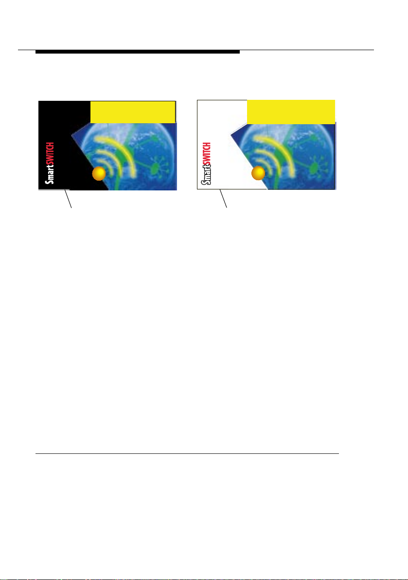
Figure 2-2 RoamAbout PC Card Identification
TM
t
u
o
b
A
m
a
o
Wireless
R
LANs
TM
t
u
o
b
R
A
m
a
o
Wireless
LANs
Black
Background
• In countries that adhere to FCC regulations
RoamAbout PC Card with the
• In France, Japan, and countries that adhere to ETSI
regulations
antenna that is used:
— You can use the RoamAbout PC Card with the
background label
RoamAbout 7-dBi Omni-Directional Antenna.
— You
background label
RoamAbout 14-dBi Directional Antenna for outdoor use.
1 As defined by the United States Federal Communications Commission
(FCC)
2 As defined by the European Telecommunications Standards Institute
(ETSI)
2
, you
must
select the card-type based upon the
when connecting the PC Card to the
must
use the RoamAbout PC Card with the
when connecting the PC Card to the
White
Background
1
, use the
black-background label
black-
.
white-
2-4 Outdoor Antenna Installation Guide
Page 25

Installation Guidelines
Overview of the Indoor Installation
When you order a RoamAbout Outdoor Kit, the kit marketed in
your country will include the correct card type that complies with
the regulations that apply in your country .
If you purchase RoamAbout outdoor antenna equipment as
separate components, make sure you order the correct items as
determined by country regulations. If you have any questions,
contact your local Cabletron Systems Sales Office for additional
information.
It is always the responsibility of the end-user to ensure
NOTE
that an outdoor antenna installation complies with local
radio regulations. The end-user must verify that:
1. The antenna installer is aware of these regulations.
2. The correct type of RoamAbout PC card is used to
connect the RoamAbout Access Point to the outdoor
antenna installation.
3. The correct type of cables and lightning protector
have been used, according to the instructions
described in this guide.
Outdoor Antenna Installation Guide 2-5
Page 26

Installation Guidelines
Overview of the Indoor Installation
Placement of the RoamAbout Access Point 2
The ideal location to install your RoamAbout Access Point must
satisfy the following requirements:
• The location must be indoors to protect the unit from extreme
weather conditions, excessive heat and humidity, and to keep
the unit free from vibration and dust.
• The location must provide a connection to a grounding type
AC wall outlet (100-240 VAC), using the standard power cord
supplied with the unit.
• The AC wall outlet ground must be connected to the same
grounding system as the
antenna mast (see
RoamAbout Lightning Protector
Grounding System
on page 2-15).
• The location must provide a connection to the network
backbone via an Ethernet LAN cable going to a hub, bridge, or
directly into a patch panel.
• The location must be as close as possible to the point where
the antenna cable will enter the building (see
Lightning Protector
on page 2-8).
Placement of the
and
2-6 Outdoor Antenna Installation Guide
Page 27

Installation Guidelines
Overview of the Indoor Installation
Prior to mounting the RoamAbout Access Point, you are advised to
carefully calculate:
• The distance between the intended location of your
RoamAbout Access Point and the location of the antenna
mast.
• The height of the antenna on the mast.
If the low-loss antenna cable is not long enough to cover this
distance, you have one of two options:
• Select another location that satisfies the requirements listed on
the previous page to mount your RoamAbout Access Point.
or
• Select another low-loss cable length (refer to Appendix C - The
Antenna Cabling System: T able C-4 on page C-8, T able C-5 on
page C-9, and Table C-6 on page C-9).
1. As the length of the antenna cable may affect the actual
NOTE
transmission/reception range of your outdoor antenna
installation, the first option is preferred.
2. Shortening the cable will void the Cabletron Systems
Warranty, and may conflict with radio certifications and/
or approvals.
Outdoor Antenna Installation Guide 2-7
Page 28

Installation Guidelines
Overview of the Indoor Installation
Placement of the Lightning Protector 2
Lightning protection is designed to protect people, property and
equipment by providing a path to the ground whenever lightning
strikes your antenna installation. The RoamAbout Lightning
Protector is an indispensable part of such a grounding system to
protect your electronic equipment from transients and/or
electrostatic discharges at the antenna.
For optimal protection, the location of the
Protector
:
RoamAbout Lightning
• Must be as close as possible to the point where the antenna
cable enters the building.
• Allow for easy installation/removal of the lightning protector
using the cables shown in Figure 2-1 on page 2-3.
• Provide a connection to the same grounding system as the
RoamAbout Access Point and the outdoor antenna mast as
described in
Grounding System
on page 2-15.
Antenna Cable Route 2
The antenna cable must be connected to the RoamAbout Access
Point via the RoamAbout Lightning Protector and Cable Assembly
as pictured in Figure 2-1 on page 2-3. To plan the route of the
antenna cable please consider the following questions:
• Does the cable route require drilling through a wall or ceiling?
• Do you have a building plan of the desired location showing
any other existing cabling routes like electricity, telephone or
networking?
• Does the building material require special tools for drilling?
• Is there adequate space and drainage for installing all
necessary antenna cable drip loops?
2-8 Outdoor Antenna Installation Guide
Page 29

Installation Guidelines
Overview of the Indoor Installation
The cable should not be installed into tight positions, as bending or
applying excessive force to the connectors may damage the
antenna cable. Always allow the cable to bend naturally around
corners.
The recommended bend radius is 25 mm (1 in.).
The antenna cable must be secured along its complete length. No
part of the antenna cable should be allowed to hang free. This is
particularly important for cable parts that are installed outdoors.
Antenna cable and cable connectors are not designed to
withstand excessive force:
!
CAUTION
1. Do not use connectors as cable grips to pull cable
through raceways or conduits.
2. Do not use cable connectors to support the weight of the
cable during or after installation.
3. Do not use tools to tighten connectors (finger-tighten
only).
4. Always seal connectors with waterproof stretch tape.
Before
sealing outdoor connectors and permanently securing
cables, verify that the installation is correct and all components
function properly.
Outdoor Antenna Installation Guide 2-9
Page 30

Installation Guidelines
Overview of the Outdoor Installation
Overview of the Outdoor Installation 2
Verify the availability of the following components required for the
outdoor installation of the point-to-point link:
• The RoamAbout Systems Antenna.
• The RoamAbout Systems low-loss antenna cable (available in
different cable lengths).
•
Antenna Mast/Wall Bracket
• An adequate
described on page 2-15.
Grounding System
(not included in kit).
that meets the requirements
• Waterproof stretch tape to seal all outdoor coax cable
connections.
2-10 Outdoor Antenna Installation Guide
Page 31

Installation Guidelines
Overview of the Outdoor Installation
Antenna Placement 2
To achieve maximum performance for your wireless outdoor
connection, the RoamAbout Outdoor Antennas must have clear
line-of-sight which is defined as:
• No obstacles in the direct path between the two antennas.
• No obstacles within a defined zone around the antenna beam.
The shape of a radio beam is not straight and narrow like a laser
beam. The radio beam, also referred to as Fresnel Zone, is bulged
in the middle, like a football or rugby ball. The exact shape and
width of the Fresnel Zone is determined by the path length and
frequency of the radio signal.
If any significant part of this zone is obstructed, a portion of the
radio energy will be lost, resulting in reduced performance.
Reduced performance may also occur when obstacles that are
close to the antenna beam cause signal reflections or noise that
interfere with the radio signal.
Figure 2-3 shows some typical examples of obstacles that you
must avoid for a directional antenna to operate effectively:
A. Neighboring Buildings
B. Trees or other obstructions
C. Power lines
To allow optimal performance, ensure that the type and placement
of the antennas allows sufficient clearance of the Fresnel Zone at
the maximum width of the bulge, typically at the midpoint between
the antennas. For more information, see
Range & Clearance
.
Outdoor Antenna Installation Guide 2-11
Chapter 3 - Determining
Page 32

Installation Guidelines
Overview of the Outdoor Installation
Figure 2-3 Potential Obstacles for a Directional Antenna
To minimize the influence of obstacles, signal interference or
reflections please note the following guidelines:
• Mount the antenna as high as possible above ground to allow
maximum clearance:
— In open areas,
— In dense urban areas
the highest obstacle in the signal path between the two
antenna sites.
ground
is the actual surface of the earth
ground
is defined as the height of
• Avoid trees or other foliage in the signal path to prevent
interference or signal absorption due to dynamic changes in
seasons (leaves/ice).
• Install the antenna at least 2 m (6 ft) away from all other
antennas.
Other situations where reflections of the radio signal may cause
interference are environments where large reflecting surfaces exist
in parallel or partly perpendicular to the antenna beam.
2-12 Outdoor Antenna Installation Guide
Page 33

Installation Guidelines
Overview of the Outdoor Installation
Environments with large reflective surfaces include:
• Buildings with mirrored-glass or low emissivity (low-e) glass
• Crowded parking lots
• Water or moist earth and moist vegetation
• Above ground power/telephone lines
Seasonal factors that could have an effect on signal propagation
may occur in the following situat ion s:
• If there are lots of trees in the signal path, marginal
communications during times of low foliage could fail at other
times when foliage is high.
• In subfreezing conditions, the communications link could fail if
an antenna is exposed to ice buildup or covered with snow.
In these cases, consult your antenna installation contractor, or take
other appropriate steps to maintain/optimize wireless performance.
Antenna Mast/Wall Bracket 2
Two examples of mounting an antenna include:
•
T ripod Mount
•
Wall (Side) Mount
Tripod Mount 2
The tripod mount is used primarily on peaked and flat roofs. The
antenna mast must be secured to the roof using 3 or 4 guy wires
that are equally spaced around the mast. When the height of the
antenna mast is more than 3 meters (10 ft), you are advised to use
at least three guy wires for each 3 meter (10 ft) section of the mast.
Outdoor Antenna Installation Guide 2-13
Page 34

Installation Guidelines
Overview of the Outdoor Installation
Wall (Side) Mount 2
A wall (side) mount allows for mounting an antenna (mast) on the
side of a building or other structure. This provides a convenient
mounting location when the roof overhang is not excessive and/or
the location is high enough to provide a clear line of sight.
• When installing the RoamAbout 14-dBi Directional Antenna,
you can mount the antenna directly to the wall, if the mounting
location allows you to aim the antenna at the opposite end of
the antenna link.
• When installing the RoamAbout 7-dBi Omni-Directional
Antenna, you must supply an antenna mast (and wall brackets
for that mast).
Antenna Mast Requirements 2
To accommodate the RoamAbout antennas, the antenna mast
must satisfy the following requirements:
1. The mast must be constructed of sturdy, weatherproof,
noncorrosive material such as galvanized or stainless steel
construction pipe.
2. Mast diameter should be between 35 mm (1.4 in.) and 42 mm
(1.6 in.).
3. Antenna mast length must be sufficient to allow an antenna
height at least 1.5 m (5 ft) above the roof peak. If the roof is
metal, the antenna height should be a minimum of 3 m (10 ft)
above the roof (see
Clearance
4. The mast or wall-bracket must be free from any substance that
may prevent a good electrical connection with the antenna; for
example, paint.
).
Chapter 3 - Determining Range &
2-14 Outdoor Antenna Installation Guide
Page 35

Installation Guidelines
Overview of the Outdoor Installation
Grounding System 2
A properly-installed safety grounding system is necessary to
WARNING
protect your RoamAbout Outdoor installation from lightning
strikes and static electricity build-up.
The grounding system must satisfy the following requirements:
1. The antenna mast, RoamAbout Access Point, and RoamAbout
Lightning Protector must be connected to the same ground,
using a low-resistance bonding conductor.
2. A good electrical connection must be made to one or more
ground rods, using at least a 10AWG ground wire and
noncorrosive hardware.
3. The grounding system must comply with electrical codes and
safety standards that apply in your locality.
4. Have a qualified electrician verify that your RoamAbout
Outdoor installation is properly grounded.
RoamAbout Antennas 2
The RoamAbout 14-dBi Directional Antenna is a Yagi antenna
designed to provide high gain for your outdoor solution while still
allowing for ease of use and installation.
The RoamAbout 7-dBi Omni-Directional Antenna is a vertical
antenna designed to provide a wide-range radio beam.
Outdoor Antenna Installation Guide 2-15
Page 36

Installation Guidelines
Overview of the Outdoor Installation
Antenna Polarization 2
Radio waves emitting from a Yagi antenna are linear, leaving the
antenna in the same plane as the antenna elements.
• When the elements are positioned
waves are
vertically
polarized.
• When the antenna elements are positioned
radio waves are
Vertical polarization is standard for the RoamAbout 14-dBi
Directional Antenna.
With RoamAbout outdoor antenna products, it does not matter
what type of polarization you choose, as long as the antenna at
one end of the communications link is mounted in the same plane
as the antenna at the other end.
In some cases you might decide to mount the antenna for
horizontal polarization. For example to minimize the influence of
cross-talk between antennas when:
horizontally
polarized.
up and down
left and right
, the radio
, the
• Multiple antennas are mounted on the same antenna mast.
• Your wireless link transmissions cross another radio beam
from a neighboring installation.
2-16 Outdoor Antenna Installation Guide
Page 37

Installation Guidelines
Overview of the Outdoor Installation
Antenna Alignment 2
For optimal performance, make sure the antennas are properly
aligned:
1. Use a pair of binoculars, a compass, and/or a map of the area
to point the antennas at each other.
2. Analyze the quality of the radio link using the AP Manager
Point-to-Point Diagnostics feature described in the
RoamAbout Access Point User’s Guide
The AP Manager Point-to-Point Diagnostics feature allows you to
display the strength of the RoamAbout radio signal relative to any
noise in the signal path (see Figure 2-4).
Figure 2-4 AP Manager Point-to-Point Diagnostics Screen
.
Outdoor Antenna Installation Guide 2-17
Page 38

Installation Guidelines
Overview of the Outdoor Installation
You can optimize antenna alignment by making small
modifications in the antenna orientation while observing the
resultant changes displayed on the AP Manager Point-to-Point
Diagnostics screen .
Aligning an omni-directional antenna is less critical due to its wide
radiation pattern.
If necessary, consult a professional Antenna Installation Service to
optimize the antenna alignment.
Antenna Cable Routing 2
The antenna cable must be routed and fixed in such a way to clear
the passage area for installation technicians.
All connectors that are located outdoors must have a weatherproof
seal. Y ou are advised to seal connectors
completed final radio tests.
only after
you have
2-18 Outdoor Antenna Installation Guide
Page 39

Installation Guidelines
Overview of the Outdoor Installation
Before Climbing the Roof... 2
Before you start the installation, check the contents of your
RoamAbout Outdoor Kit. If there are signs of shipping damage,
contact the shipping carrier to file a claim.
Verify that you have all of the items required for the installation:
1. RoamAbout Access Point.
2. RoamAbout PC Card.
3. RoamAbout 50-cm Cable Assembly.
4. RoamAbout Lightning Protector.
5. Low-loss antenna cable. Depending on your order, this cable
length is either 6 m (20 ft), 15 m (50 ft) or a 22 m (75 ft).
6. RoamAbout Outdoor Antenna. Depending on the antenna
components you ordered, this is either:
• The RoamAbout 14-dBi Directional Antenna (an
encapsulated yagi antenna).
or
• The RoamAbout 7-dBi Omni-Directional Antenna.
7. RoamAbout Wall Mount Kit (instructions included with kit).
Outdoor Antenna Installation Guide 2-19
Page 40

Page 41

Determining Range & Clearance
3
The Fresnel Zone 3
As identified in
clear line-of-sight to set up an outdoor antenna installation that
meets your requirements in terms of range and throughput
performance.
A
NOTE
In Chapter 2, we described the shape of the radio beam (Fresnel
Zone) as being bulged in the middle. The exact shape and width of
the Fresnel Zone is determined by the path length and frequency
of the radio signal.
If any significant part of the Fresnel Zone is obstructed, a portion of
radio energy is lost, resulting in reduced performance. For optimal
performance, you must ensure that the antenna products you
choose, in combination with the height of the antenna installation
above ground, will provide sufficient clearance to allow your
antenna installation to cover the distance between the two wireless
sites.
wireless outdoor antenna connection that lacks sufficient
clearance will suffer from poor performance. When radio
performance is poor, the network response is poor as well,
due to many retransmission attempts of lost data frames.
Chapter 2 - Installation Guidelines
, you need a
Outdoor Antenna Installation Guide 3-1
Page 42

Determining Range & Clearance
The Fresnel Zone
As shown in Figure 3-1, there are two major variables that
determine the shape of the Fresnel Zone:
• The distance between the antennas (1)
• The minimum clearance required for optimal performance (2).
Figure 3-1 Fresnel Zone
R
o
a
m
A
b
o
u
t
1
2
R
o
a
m
A
b
o
u
t
1
2
2844-01-03A
Refer to the following table to determine the minimum clearance
required for your installation as defined by the distance between
the antennas. For more information, refer to
Calculating Range & Clearance
Distance Between Antennas (1) Minimum Clearance Required (2)
kilometers (miles) meters (feet)
2.1 (1.3) 5.8 (19.1)
3.5 (2.2) 7.8 (25.7)
6.5 (4.0) 11.1 (36.5)
9.6 (6.0) 14.4 (47.4)
.
Appendix D -
3-2 Outdoor Antenna Installation Guide
Page 43

Determining Range & Clearance
Other Considerations
Other Considerations 3
In most literature concerning wireless outdoor products, two
parameters are usually listed to indicate transmitted signal
strength:
system.
output power
of the radio, and
gain
of the antenna
• Output Power of radio equipment is often subject to maximum
limits as defined by local radio regulations. Consequently
Output Power is not by definition the way to enhance wireless
performance.
• High gain antennas are larger in size than low gain antennas,
and are characterized by a narrow focus of the radio beam.
These two characteristics make it more difficult to aim the
antennas, and/or adjust antenna alignment to optimize the
performance of the wireless point-to-point link.
With these points in mind, the design of antennas and components
supplied with the RoamAbout Outdoor Kit are based upon the
following principles:
• An output power and antenna gain that comply with the
maximum limits as defined by local governing bodies
concerning radio transmissions.
• Enhanced radio sensitivity for optimal reception of RoamAbout
radio signals transmitted by remote antennas.
Refer to
information to help you calculate the optimal range of your antenna
system.
Appendix D - Calculating Range & Clearance
Outdoor Antenna Installation Guide 3-3
for detailed
Page 44

Page 45

Installing the Antenna
4
Planning the Antenna Installation 4
Carefully plan your antenna installation. Do not install the
WARNING
antenna in wet, windy, icy, or otherwise unsafe weather
conditions.
The grounding system for the antenna mast, RoamAbout Access
Point, and RoamAbout Lightning Protector should be installed
before
the cable from the antenna is connected to the lightning
arrestor. This will protect you and your equipment in case lightning
should strike the antenna during installation.
Familiarize yourself with the antenna and the antenna specific
mounting instructions prior to climbing any roof or ladder. Installing
and testing all equipment before beginning the actual rooftop
installation will help you to determine whether all required
equipment and items are available and are functioning properly.
!
CAUTION
When testing the outdoor antennas in an indoor
environment, we recommend that you keep the antennas
back to back to avoid excessively strong radio signals.
Outdoor Antenna Installation Guide 4-1
Page 46

Installing the Antenna
Planning the Antenna Installation
To verify the equipment prior to installation, you may need to
proceed with the guidelines described in the
Point User’s Guide
chapter. The
with the RoamAbout Access Point, and can be downloaded from
the RoamAbout website at:
before performing the procedures in this
RoamAbout Access Point User’s Guide
http://www.cabletron.com/wireless
RoamAbout Access
is shipped
Safety Precautions 4
Please read this section carefully before starting the installation. All
requirements listed below should be satisfied prior to starting
installation of your RoamAbout outdoor antennas.
Do not climb rooftops in wet or windy conditions, during a
WARNING
thunderstorm, or when the area where the equipment will be
installed is covered with ice or snow.
ELECTRICAL HAZARD WARNINGS
1. Antennas and cables are electrical conductors. Do not
touch antennas, RoamAbout Lightning Protectors, or
antenna cables during a thunderstorm.
2. The location where you install each antenna must be at
a safe distance from power lines or telephone lines. The
safe distance should be at least twice the height of the
antenna mast plus the height of the antenna.
3. The Contact between antenna components and power
lines can result in serious personal injury, or possibly
death.
4. Do not install antennas or cables where there is any
possibility of contact with high-voltage arc-over from
power cables or service drops to buildings.
5. During installation or removal, the antenna, supporting
mast and/or tower must not be close to any power lines.
4-2 Outdoor Antenna Installation Guide
Page 47

Installing the Antenna
Planning the Antenna Installation
ELECTRICAL HAZARD WARNINGS (Continued)
6. The low-loss antenna cable that connects the antenna to
the lightning protector must be at least 1m (3 ft) away
from any high voltage or high current cable.
7. Check whether the antenna mast and its guy wires or
wall bracket are positioned correctly and secured
properly to the roof or wall(s).
8. Check whether the grounding system for the antenna
mast, the RoamAbout Access Point, and RoamAbout
Lightning Protector have been installed. The grounding
system must comply with the requirements as described
in Chapter 2, Grounding System on page 2-15.
9. Always consult a qualified electrician if you are in doubt
as to whether the antenna mast, Lightning Protector,
and/or RoamAbout Access Point is properly grounded.
10. The low-loss antenna cable between the antenna and
the lightning arrestor must be grounded at all times. If
the cable is disconnected at one end for some reason
(for example, to replace the lightning arrestor), you must
locally ground the exposed metal connector of the cable
during the work.
11. Install the Danger label shipped with the antenna on a
plainly visible area of the antenna support structure.
Outdoor Antenna Installation Guide 4-3
Page 48

Installing the Antenna
Planning the Antenna Installation
Installation Overview 4
NOTE
components.
The installation process is summarized in the following steps:
1. Make sure the AP’s are configured as specified in the
Installation Checklist
2. Verify that the antenna support structure is connected to the
grounding system.
3. Connect the exposed metal connectors of the low-loss
antenna cable to the grounding system.
4. Mount the antenna to the support structure, following the
guidelines as described for your antenna:
•
Mounting the Directional Antenna
•
Mounting the Omni-directional Antenna
5. Connect the antenna cable to the antenna.
6. Route the antenna cable to the RoamAbout Lightning
Protector which has been installed indoors.
7. Connect the antenna cable to the Lightning Protector.
8. Connect the Cable Assembly to the Lightning Protector.
9. Connect the opposite end of the Cable Assembly to the
connector in the extended part of the RoamAbout PC Card.
on page 2-2.
on page 4-5.
on page 4-8.
Refer to Appendix C to identify antenna installation
Pre-
When you remove or relocate the antenna, follow the Safety
WARNING
Precautions described on page 4-2, and perform the steps
above in reverse order.
10. Run the AP Manager Point-to-Point Diagnostics program to
aim the antenna and verify optimal placement.
4-4 Outdoor Antenna Installation Guide
Page 49

Installing the Antenna
Mounting the Antenna
1 1. After verifying that the communications link is fully operational,
secure all cables and use weatherproofing tape to seal all
outdoor connectors.
Mounting the Antenna 4
The RoamAbout antennas are available as a RoamAbout 14-dBi
Directional and a RoamAbout 7-dBi Omni-Directional. This section
includes mounting instructions for each of these antenna types.
When mounting multiple antennas on a single mast, use the
following methods to minimize cross-talk between antennas:
• Place the antennas as far apart as possible.
• Alternate the mounting of directional antennas for vertical and
horizontal polarization (figures on the following pages illustrate
mounting for
vertical
Mounting the Directional Antenna 4
polarization).
You can mount the RoamAbout 14-dBi Directional Antenna on a
mast or on a flat vertical surface such as a wall. In most cases,
mounting the antenna on a mast allows more flexibility in adjusting
the height and direction of the antenna in order to better aim it at
the opposite end of the wireless link.
Mounting on a Mast 4
To mount the RoamAbout 14-dBi Directional Antenna on a mast,
proceed as follows:
1. Verify that you have all the items listed below:
• The RoamAbout 14-dBi Directional Antenna
• A metal backing plate (included with antenna)
• Two U-bolts and two clamps (included with antenna)
Outdoor Antenna Installation Guide 4-5
Page 50

Installing the Antenna
Mounting the Antenna
• Four flatwashers and four nuts (included with antenna)
• A socket wrench to tighten the nuts
2. Note the arrows on the plastic antenna mounting base.
3. Install the antenna with the arrows pointing up.
4. Attach the antenna mounting base and metal backing plate to
the mast using U-bolts, clamps, flat washers and nuts as
shown in Figure 4-1.
Always place flatwashers between nuts and the plastic
antenna mounting base. Avoid overtightening the nuts to
!
CAUTION
prevent damage to the plastic antenna mounting base.
5. Proceed to
Connecting the Antenna Cable
on page 4-10.
Figure 4-1 Mounting the 14-dBi Antenna to a Mast
Side View
Top View
Direction of Maximum Signal
Clamp
Backing Plate
Antenna Mounting Base
Flatwasher
Always place flatwashers between
nuts and the Antenna Mounting Base.
4-6 Outdoor Antenna Installation Guide
Page 51

Installing the Antenna
Mounting the Antenna
Mounting on a Flat Surface 4
When mounting the antenna on a flat vertical surface, you must
provide a smooth surface for the backing plate. On wall surfaces
such as brick, block or stucco, install an intermediate plate
between the wall and the backing plate. The intermediate plate
must be strong enough to prevent distortion of the backing plate
and the plastic antenna mounting base when the mounting
hardware is tightened.
To mount the antenna proceed as follows:
1. Verify that you have all the items required for your particular
installation:
• The RoamAbout 14-dBi Directional Antenna
• A backing plate (included with antenna)
• An intermediate plate (not included)
• All mounting hardware required for your particular
installation
• All tools required for your particular installation
2. Note the arrows on the antenna mounting base.
3. Mount the antenna with the arrows pointing up.
4. Attach the antenna mounting base, metal backing plate and
intermediate plate to the wall using hardware required for your
particular installation (see Figure 4-2).
5. Proceed to
Connecting the Antenna Cable
on page 4-10.
Outdoor Antenna Installation Guide 4-7
Page 52

Installing the Antenna
Mounting the Antenna
Figure 4-2 Mounting the 14-dBi Antenna to a Wall
Direction of Maximum Signal
Backing Plate
Antenna Mounting Base
Flatwasher
Always place Flatwashers between nuts or
bolts and Antenna Mounting Base!
Intermediate Plate (not included). Required when
mounting antenna on a rough surface.
Always use flatwashers between the mounting screws/nuts
and the plastic antenna mounting base. Avoid overtightening
!
CAUTION
the mounting screws/nuts to prevent damage to the antenna
mounting base.
Mounting the Omni-directional Antenna 4
It is recommended that you mount the RoamAbout 7-dBi OmniDirectional antenna to a mast. Proceed as follows:
1. Verif y that you have the fol lowi ng items :
• The RoamAbout 7-dBi Omni-Directional Antenna
• A metal mounting bracket (included)
• Two hose-clamps (included)
• Nut and lockwasher (included)
• A standard screwdriver or small wrench to tighten the nut
on each hose-clamp
4-8 Outdoor Antenna Installation Guide
Page 53

Installing the Antenna
Mounting the Antenna
Figure 4-3 Mounting the Om ni-Directional An tenna to a Mast
H
G
F
A
B
C
D
E
2. Referring to Figure 4-3, make sure the gasket (B) is installed
on the antenna mounting base (A).
3. Insert the threaded portion of the antenna mounting base
through the hole in the top of the metal mounting bracket (F).
4. Secure the antenna to the metal mounting bracket using
lockwasher (C) and nut (D).
5. Slide two hose-clamps (G) over the mast (H).
Outdoor Antenna Installation Guide 4-9
Page 54

Installing the Antenna
Connecting the Antenna Cable
6. Secure the metal mounting bracket (with antenna) to the mast
using two hose-clamps.
Avoid overtightening each hose-clamp nut to avoid damage
to the hose-clamp and/or antenna.
!
CAUTION
7. Connect the outdoor portion of the antenna cable (E) to the
threaded portion of the antenna mounting base.
8. Proceed to
Connecting the Antenna Cable
.
Connecting the Antenna Cable 4
Once the antenna is properly installed, you can connect the
antenna to the RoamAbout Access Point via the RoamAbout
Lightning Protector.
1. V erify that the low-loss antenna cable is properly connected to
the antenna.
2. Secure the antenna cable to the mast such that the cable
connectors do not support the full weight of the cable.
3. Provide a drip-loop at the bottom of the cable just before it
enters the building.
4. Connect the opposite end of the antenna cable to the
RoamAbout Lightning Protector.
To avoid damage to the antenna cable and connectors, do
not use tools to tighten cable connectors.
!
CAUTION
4-10 Outdoor Antenna Installation Guide
Page 55

Installing the Antenna
Connecting the Antenna Cable
5. Prior to securing the cable along its complete length, run the
Point-to-Point diagnostics of the RoamAbout Access Point
Manager program to analyze wireless performance and
optimal placement of the outdoor antenna (see Figure 2-4 on
page 2-17).
NOTE
CAUTION
The RoamAbout Access Point Manager program is
described in the RoamAbout Access Point User’s Guide,
which is shipped with the RoamAbout Access Point.
6. If required, adjust the direction of the antenna.
7. Once the installation has been fully tested, tighten antenna
mounting nuts to lock the antenna into its position.
To prevent damage, avoid overtightening the connectors,
nuts, and screws used to mount the antenna.
!
8. Secure the cable along its complete length. No part of the
cable should be allowed to hang free. This is especially
important for those parts that are routed outside the building.
9. Use waterproof stretch tape to seal all outdoor connectors.
Outdoor Antenna Installation Guide 4-11
Page 56

Installing the Antenna
Connecting the Antenna Cable
Sealing the Cable Connectors 4
Most problems associated with wireless outdoor installations are
related to degrading performance due to the effects of corrosion of
the antenna cable and cable connectors. To avoid this type of
problem, always seal the cable connectors that are located
outdoors using waterproof stretch tape.
after
You are advised to seal the connectors
optimal antenna alignment. Doing so will enable you to adjust
antenna placement and cable routing without removing the tape.
1. Prepare the cable and connectors so that they are free from
dust, dirt and grease.
2. Attach the tip of the weather proofing tape to the cable just
above the connector.
3. Hold the tape in position, and stretch the tape and wind it halflapped around the cable and connectors to form a void-free
joint.
The degree of stretch can vary in different sections of the joint,
as long as the overlaps accomplish a void-free application.
you have verified
To protect the weatherproofing stretch tape from the effects
of Ultra-Violet (UV) radiation (for example from direct
!
CAUTION
4-12 Outdoor Antenna Installation Guide
sunlight), you should protect the joint with two half-lapped
layers of any vinyl-plastic electrical tape. Alternatively, you
can apply silicone sealer to protect the weatherproofing tape
from sunlight, rain and other weather conditions.
Page 57

The RoamAbout 14-dBi Directional Antenna
A
General Description 1
The RoamAbout 14-dBi Directional Antenna is a high-gain antenna
for the 2.4 GHz frequency band.
The antenna is a totally enclosed 16-element Yagi designed for
point-to-point communicatio ns.
It has a typical VSWR of 1.5:1 and is less than 2:1 over the entire
frequency band. The gain is 14-dBi and the half-power beamwidth
is 30 degrees. This antenna is normally mounted on a mast and is
vertically polarized.
Contents of the Antenna Box 1
• One antenna
• Metal Backing Plate for the antenna
• Two U-bolt clamps (for mast mounting)
• Four flatwashers, and four nuts
(to attach the antenna to the U-bolt clamps).
• Manual
For mounti ng instructions plea se consult
Antenna
.
Outdoor Antenna Installation Guide A-1
Chapter 4 - Installing the
Page 58

The RoamAbout 14-dBi Directional Antenna
General Description
Table A-1 Specifications 14-dBi Directional Antenna
Mechanical
• Size 45.7 cm (18 in)
• Mounting Me thod • Vertical mast with an outside diameter
between 35 mm (1.4 in) and 42 mm
(1.6 in) using u-bolts.
• Wall using plugs and screws.
Cable
• Type RG-58A/U, 50 ohm low-loss coax
• Length 20 cm (7.5 in)
• Color White
Connector
1
• FCC Countries Reverse Polarity-N (Male)
• ETSI Countries Standard-N (Female)
• France Standard-N (Female)
• Japan Standard-N (Female)
Electrical
• Frequency Range 2.4 GHz
• VSWR Less than 2:1, 1.5:1 Nominal
• Nominal Impedance 50 Ohms
• Gain 14 dBi
• Front-to-Back Ratio greater than 20 dB
• Half-Power Beamwidth (-3 dB)
• Vertical (E-plane °) 30.8 Degrees
• Horizontal (H-pla ne °) 31.4 Degrees
• Polarization Linear, Vertical or Horizontal (see page 4-5).
Antenna Environment
• Operating Temperature +60°C (140°F) - 40°C (-40°F)
• Wind/survival (mph) At least 128 km/h (80 mph)
2
• Wind Surface Area 7.56 square cm (0.248 square ft)
1 See Selecting the Correct Connector Type on page C-1.
2 At least 104 km/h (65 mph) with 1.25 cm (0.5 in) ice.
A-2 Outdoor Antenna Installation Guide
Page 59

The RoamAbout 7-dBi OmniDirectional Antenna
B
General Description 2
The RoamAbout 7-dBi Omni-Directional Antenna is a broadband
antenna for the 2.4 GHz frequency band featuring an omnidirectional pattern with a nominal gain of 7 dBi.
This antenna is encapsulated in a weatherproof protective
covering. With the hardware provided, this vertically-polarized
antenna can be mounted on an antenna mast with an outside
diameter of up to 51mm (2 in).
For mounting instructions, refer to
Antenna
For detailed specifications see Table B-1 on page B-2.
Contents of the Antenna Box 2
• One encapsulated antenna
• Metal mounting bracket
• Two hose clamps
• Nut and lockwasher
For mounti ng instructions plea se consult
Antenna
.
.
Outdoor Antenna Installation Guide B-1
Chapter 4 - Installing the
Chapter 4 - Installing the
Page 60

The RoamAbout 7-dBi Omni-Directional
Antenna
General Description
Table B-1 Specifications of the 7-dBi Omni-Directional Antenna
Mechanical
• Size 45,7 cm (18 in.)
• Mounting method Clamps to ver tical mast with outside
diameter up to 51mm (2 in.)
Cable
• Type RG-58A/U, 50 ohm low-loss coax
• Length 15 cm (6 in.)
• Color White
Connector
1
• FCC Countries Reverse Polarity-N (male)
• ETSI Countries Standard-N (female)
• France Standard-N (female)
• Japan Standard-N (female)
Electrical
• Frequency Range 2.4 GHz
• VSWR Less than 2:1 Nominal
• Nominal Impedance 50 Ohms
• Gain 7 dBi
• Polarization Linear Vertical
Antenna Environment
• Operating Temperature +60°C (140°F) - 40°C (-40°F)
• Wind/survival (mph) At least 128 km/h (80 mph)
2
• Wind Surface Area 7.56 square cm (0.248 square feet)
1 See Selecting the Correct Connector Type on page C-1.
2 At least 104 km/h (65 mph) with 1.25 cm (0.5 in.) ice.
B-2 Outdoor Antenna Installation Guide
Page 61

The Antenna Cabling System
The Outdoor Cabling Components 3
To connect your RoamAbout Access Point to an
outdoor antenna installation you will need the
following cabling components as pictured on the
right side of this page:
A. RoamAbout Cable Assembly
B. RoamAbout Lightning Protector
C. Low-Loss Antenna Cable
D. Outdoor Antenna Cable:
• The RoamAbout 14-dBi Directional
Antenna (described in Append ix A), or
• The RoamAbout 7-dBi Omni-Directional
Antenna (described in App end ix B)
C
Selecting the Correct Connector Type 3
Subject to the country where the RoamAbout
Outdoor Kit and/or antennas are purchased, the
components listed above are equipped with either
Standard N-Type connectors or Reverse Polarity
N-Type connectors.
Outdoor Antenna Installation Guide C-1
Page 62

The Antenna Cabling System
Standard-N Male
Standard-N Female
The Outdoor Cabling Components
When ordering separate components, ensure that you order
products with the correct N-Type connector to match the other
outdoor cabling components that apply to your country
The term Male or Female is not related to the thread of the
NOTE
connector, but to its center pin.
•
Male connectors have a solid center pin.
•
Female connectors have a hollow center pin.
Table C-1 Selecting the Correct N-Type Connector
Pigtail
Connection
(A)
ETSI Countries, France & Japan FCC Countries
1 - PC Card connector 1 - PC Card connector
A
2 - Standard-N male 2 - Reverse Polarity-N Female
Standard-N Female
B
(both ends)
Standard-N Male
C
(both ends)
Standard-N Female Reverse Polarity-N Male
D
21
Lightning
Protector
(B)
Low-Loss
Cable
(C)
Reverse Polarity-N Female
Reverse Polarity-N Male
Reverse Polarity-N Male
(both ends)
Reverse Polarity-N Female
(both ends)
Antenna
Cable
(D)
C-2 Outdoor Antenna Installation Guide
Page 63

The Antenna Cabling System
The Outdoor Cabling Components
ELECTRICAL HAZARD WARNINGS
1. Outdoor antennas and antenna cables are electrical
conductors. Transients or electrostatic discharges that
may occur at the antenna (e.g., lightning) may damage
your electronic equipment and cause personal injury or
death to persons touching the exposed metal connectors
of the antenna cable.
2. To avoid damage and personal injury, the entire antenna
cabling system must be grounded at all times.
3. When installing, disconnecting or replacing one of the
cabling components, you must ensure at all times that
each exposed metal connector of the antenna cabling
system is grounded locally during the work. For example
when mounting or replacing the RoamAbout Lightning
Protector:
•
Connect each of the low-loss antenna cable
connectors to the grounding system.
•
Connect the RoamAbout 50-cm Cable Assembly
connector to the grounding system.
•
Connect the RoamAbout Lightning Protector to the
grounding system.
4. Before you proceed, verify that each component is
properly grounded and that the ground is not interrupted
when disconnecting any one of the antenna system
components.
5. Check with a qualified electrician if you are in doubt as to
whether the lightning protector and cable connectors are
properly grounded.
6. Only after verifying that each item is properly grounded,
replace the lightning protector and reconnect the cables in
reverse order.
Outdoor Antenna Installation Guide C-3
Page 64

The Antenna Cabling System
RoamAbout Cable Assembly
RoamAbout Cable Assembly 3
The RoamAbout Cable Assembly is a proprietary cable used to
connect the RoamAbout PC Card to a RoamAbout outdoor
antenna system. This cable is included in the RoamAbout Outdoor
Kit.
One end of the cable has a proprietary connector which is
connected to the RoamAbout PC Card.
The N-Type connector at the opposite end of the cable matches
the polarity of the N-connectors of the other components that are
part of your outdoor antenna cabling system, subject to the country
where the RoamAbout Outdoor Kit and/or Cable Assembly was
purchased.
Table C-2 Cable Assembly Specifications
Mechanical
Length 50 cm (19.5 in)
Connectors
1
• FCC Countries Reverse Polarity-N (Female)
• ETSI Countries Standard-N (Male)
• France Standard-N (Male)
• Japan Standard-N (Male)
Operating Te mperature -40°C to +85°C (-40°F to +185°F)
Electrical
Frequency Range 800-2500 MHz
Insertion Loss 0.9 dB
1 See
C-4 Outdoor Antenna Installation Guide
Selecting the Correct Connector Type
on page C-1.
Page 65

The Antenna Cabling System
RoamAbout Lightning Protector
RoamAbout Lightning Protector 3
The RoamAbout Lightning Protector is a surge arrestor that
protects your sensitive RoamAbout equipment from high-voltage
currents caused by discharge and transients at the antennas.
Table C-3 lists the specifications for the RoamAbout Lightning
Protector.
Table C-3 Lightning Protector Specifications
Mechanical
Size
Height 69 mm (2.7 in)
Diameter 26 mm (1 in)
Weight 133 g (4.7 oz.)
Connectors
1
• FCC Countries Reverse Polarity-N (Male on both ends)
• ETSI Countries Standard-N (Female on both ends)
• France Standard-N (Female on both ends)
• Japan Standard-N (Female on both ends)
Operating Temperature -40°C to +85°C (-40°F to +185°F)
Electrical
Frequency Range 800-2500 MHz
Insertion Loss 0.2 dB
Surge Current 2000 Amp
Nominal Impedance 50 Ohms
1 See
Selecting the Correct Connector Type
on page C-1.
Outdoor Antenna Installation Guide C-5
Page 66

The Antenna Cabling System
RoamAbout Lightning Protector
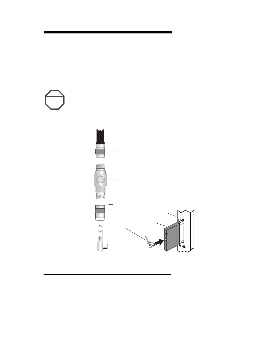
Installation 3
To install the RoamAbout Lightning Protector:
1. Determine a suitable location for the Lightning Protector as
described in Chapter 2 - Installation Guidelines.
2. As shown in Figure C-1, secure bracket (A) to the wall using
two screws (F).
Figure C-1 Lightning Protector Installation
A
B
E
C
D
3. Use a ring-terminal to connect ground-wire (C) to bolt (B).
ring-terminal and ground wire are provided by the installer
4. Secure bolt (B) to the bracket using washers and locknut (D).
5. Loosely install washers and hexnut (G) onto the RoamAbout
Lightning Protector (E).
C-6 Outdoor Antenna Installation Guide
F
G
The
.
Page 67

The Antenna Cabling System
RoamAbout Lightning Protector
6. Insert the Lightning Protector into the opening in bracket (A).
7. Tighten hexnut (G) to secure the RoamAbout Lightning
Protector in its position, and ensure that the Protector is
properly connected to the grounding system.
To avoid damage to electronic equipment and your
RoamAbout equipment, always install the RoamAbout
!
CAUTION
Lightning Protector between the outdoor antenna installation
and the RoamAbout Access Point or other computing device
connected to the outdoor antenna.
Routine Maintenance 3
Routine maintenance is required for each RoamAbout Lightning
Protector in your outdoor antenna installation. Maintenance
involves replacing the Gas Discharge Tube (GDT) at some interval
depending on the lightning/transient discharge activity in your
area.
NOTE
Contact a local antenna installation company to determine
the maintenance schedule for each RoamAbout Lightning
Protector in your outdoor antenna installation.
Outdoor Antenna Installation Guide C-7
Page 68

The Antenna Cabling System
Low-Loss Antenna Cable
Low-Loss Antenna Cable 3
A 15m (50 ft) Low-loss antenna cable is included in the
RoamAbout Outdoor Kit (seeTable C-5). Cable is also available in
two other standard lengths:
•
6m (20 ft) - see Table C-4
•
22m (75 ft) - see Table C-6
To ensure you order the right cable length, carefully determine the
distance between the locations where you intend mounting the
RoamAbout Access Point and outdoor antenna.
Table C-4 Cable Specifications for the 6m (20 ft) Antenna
Mechanical Specifications
Length 6 meter (20 ft)
Diameter 5 mm (0.195 in)
Weight 32,75 gram/meter (0.022 lbs/ft)
Bend Radius
Connectors
1
• FCC Countries Reverse Polarity-N (Female on both ends)
• ETSI Countries Standard-N (Male on both ends)
• France Standard-N (Male on both ends)
• Japan Standard-N (Male on both ends)
Operating Te mperature -40°C to +85°C (-40°F to +185°F)
Electrical Specifications
Insertion Loss 0.55 dB/meter (16.9 dB/100 feet)
Total for this cable 3.5 dB
1 See
C-8 Outdoor Antenna Installation Guide
Selecting the Correct Connector Type
on page C-1.
Page 69

The Antenna Cabling System
Low-Loss Antenna Cable
Table C-5 Cable Specifications for the 15m (50 ft) Antenna
Mechanical Specifications
Length 15 meter (50 ft)
Diameter 10 mm (0.4 in)
Weight 101.2 gram/meter (0.068 lbs/ft)
Bend Radius 25 mm (1 in)
Connectors
1
• FCC Countries Reverse Polarity-N (Female on both ends)
• ETSI Countries Standard-N (Male on both ends)
• France Standard-N (Male on both ends)
• Japan Standard-N (Male on both ends)
Operating Temperature -40°C to +85°C (-40°F to +185°F)
Electrical Specifications
Insertion Loss 0.22 dB/meter (6.8 dB/100 feet)
Total for this cable 3.5 dB
Table C-6 Cable Specifications for the 22m (75 ft) Antenna
Mechanical Specifications
Length 22 meter (75 ft)
Diameter 10 mm (0.4 in)
Weight 101.2 gram/meter (0.068 lbs/ft)
Bend Radius 25 mm (1 in)
Connectors
1
• FCC Countries Reverse Polarity-N (Female on both ends)
• ETSI Countries Standard-N (Male on both ends)
• France Standard-N (Male on both ends)
• Japan Standard-N (Male on both ends)
Operating Temperature -40°C to +85°C (-40°F to +185°F)
Electrical Specifications
Insertion Loss 0.22 dB/meter (6.8 dB/100 feet)
Total for this cable 5.1 dB
Outdoor Antenna Installation Guide C-9
Page 70

Page 71

Calculating Range & Clearance
D
Introduction 4
This appendix presents reference information to help you:
• Calculate the typical and/or maximum communications range
you can achieve using components available in the
RoamAbout Outdoor Kit.
• Select optimal antenna height for your installation.
• Determine which antennas and/or cables you need to cover a
predefined distance.
This information along with other considerations described in this
appendix allow you to accurately determine the
Budget
for your specific installation.
Dynamic Range
Outdoor Antenna Installation Guide D-1
Page 72

Calculating Range & Clearance
The Dynamic Range Budget
The Dynamic Range Budget 4
The Dynamic Range Budget is the sum of the following factors as
determined at both ends of the wireless outdoor link:
• Type of RoamAbout Outdoor Antenna:
— RoamAbout 7-dBi Omni-Directional Antenna, or
— RoamAbout 14-dBi Directional Antenna
• Length of the Antenna Cable required to connect the
RoamAbout Access Point to the outdoor antenna.
• Type of RoamAbout PC Card used
— The RoamAbout PC Card with the
or
— The RoamAbout PC Card with the white
To determine the Dynamic Range Budget that applies in your
situation, use either Table D-1 on page D-3, or Table D-2 on page
D-4 (subject to radio regulations that apply in your country):
1
:
black-background label
-background labe l.
• Use Table D-1, for the USA, Canada, and any other country
that adheres to the radio regulations as defined by the United
States Federal Communications Commission (FCC).
• Use Table D-2, for all European countries, Japan, and any
other countries that adhere to the radio regulations as defined
by the European Telecommunications Standards Institute
(ETSI).
,
To determine the Dynamic Range Budget, use the horizontal axis
of the table to select the equipment installed in building X, and the
vertical axis to select the equipment in building Y.
1 The choice of this card is subject to local radio regulations (see
the Right RoamAbout PC Card
D-2 Outdoor Antenna Installation Guide
on page 2-3).
Selecting
Page 73

Calculating Range & Clearance
Table D-1 Dynamic Range (FCC)
Link Speed Antenna Type Omni-Directional 7-dBi Directional 14-dBi
Cable Length 6m (20 ft) /
15m (50 ft)
Outdoor Antenna Installation Guide D-3
2 MBit/s
Link Speed Antenna Type Omni-Directional 7-dBi Directional 14-dBi
1 Mbit/s
The diameter of the 15m (50 f t) an d 22 m (75 ft) cables is larger than the diameter o f the 6m (20 ft) c abl e.
Therefore the cable loss of 50 ft cables is the same as for 20 ft cables, resulting in the same Dynamic Range
Budget value.
Omni-Directional 7-dBi
Directional 14-dBi
Omni-Directional 7-dBi
Directional 14-dBi
6m (20 ft) /
15m (50 ft)
22m (75 ft) 108.5 dB 106.8 dB 115.5 dB 113.8 dB
6m (20 ft) /
15m (50 ft)
22m (75 ft) 115.5 dB 113.8 dB 122.5 dB 120.8 dB
Cable Length 6m (20 ft) /
6m (20 ft) /
15m (50 ft)
22m (75 ft) 111.5 dB 109.8 dB 118.5 dB 116.8 dB
6m (20 ft) /
15m (50 ft)
22m (75 ft) 118.5 dB 116.8 dB 125.5 dB 123.8 dB
110.2 dB 108.5 dB 117.2 dB 115.5 dB
117.2 dB 115.5 dB 124.2 dB 122.5 dB
15m (50 ft)
113.2 dB 111.5 dB 120.2 dB 118.5 dB
120.2 dB 118.5 dB 127.2 dB 125.5 dB
22m (75 ft) 6m (20 ft) /
15m (50 ft)
22m (75 ft) 6m (20 ft) /
15m (50 ft)
22m (75 ft)
22m (75 ft)
The Dynamic Range Budget
Page 74

Calculating Range & Clearance
D-4 Outdoor Antenna Installation Guide
Table D-2 Dynamic Range (ETSI. France & Japan)
Link Speed Antenna Type Omni-Directional 7-dBi Directional 14-dBi
Cable Length 6m(20 ft) /
15m (50 ft)
Omni-Directional 7-dBi 6m (20 ft) /
2 Mbit/s
Directional 14-dBi 6m (20 ft) /
Link speed Antenna Type Omni-Directional 7-dBi Directional 14-dBi
1 Mbit/s
The diameter of the 15m (50 ft) and 22m (75 ft) cables is larger than the diameter of the 6m (20 ft) cable.
Therefore the cable loss of 50 ft cables is the same as for 20 ft cables, resulting in the same Dynamic Range
Budget value.
Omni-Directional 7-dBi
Directional 14-dBi
15m (50 ft)
22m (75 ft)
15m (50 ft)
22m (75 ft) 108.5 dB 106.8 dB 115.5 dB 113.8 dB
Cable Length 6m (20 ft) /
6m (20 ft) /
15m (50 ft)
22m (75 ft)
6m (20 ft) /
15m (50 ft)
22m (75 ft) 111.5 dB 109.8 dB 118.5 dB 116.8 dB
110.2 dB 108.5 dB
108.5 dB 106.8 dB
110.2 dB 108.5 dB 117.2 dB 115.5 dB
15m (50 ft)
113.2 dB 111.5 dB
111.5 dB 109.8 dB
113.2 dB 111.5 dB 120.2 dB 118.5 dB
22 m (75 ft) 6m (20 ft) /
15m (50 ft)
110.2 dB 108.5 dB
108.5 dB 106.8 dB
22m (75 ft) 6m (20 ft) /
15m (50 ft)
113.2 dB 111.5 dB
111.5 dB 109.8 dB
22m (75 ft)
22m (75 ft)
The Dynamic Range Budget
Page 75

Calculating Range & Clearance
The Dynamic Range Budget
Link speed versus Range 4
For the values referenced in Table D-2 on page D-4,
NOTE
each 7-dBi antenna is connected to the RoamAbout PC
Card with a black-background label.
For the values referenced in Table D-2, each 14-dBi
antenna is connected to the RoamAbout PC Card with a
white-background lab el.
•
The values pri n t ed in ita li c s us e a bl a ck- ba ck gr ou n d
RoamAbout PC Card at each end of the wireless
link.
•
All other values use a white-background RoamAbout
PC Card at one or both ends of the antenna link.
The listed Dynamic Range Budget values include the
loss of the mandatory RoamAbout Lightning Protector.
Communications at lower data speeds may travel longer
distances. In situations where range is more critical to your
network than data speed, you may wish to limit the data speed to
1Mbit/s to increase the range of your wireless point-to-point link.
We have included the Dynamic Range Budgets for both 2 Mbit/s
and 1 Mbit/s links with each table to help you determine which data
speed is appropriate for your situation.
Determine Line-of-Sight Clearance 4
Use T able D-3 on page D-6 to determine the minimum clearance of
the signal path clearance required to achieve the maximum
possible range with the type of antennas and cable lengths you
selected.
Outdoor Antenna Installation Guide D-5
Page 76

Calculating Range & Clearance
The Dynamic Range Budget
To read Table D-3 correctly:
• Use the Dynamic Range Budget value that you read from
either Table D-1 or Table D-2.
• Locate this value in Table D-3:
— V alues marked with an asterisk (*) in Table D-3 correspond
to Dynamic Range Budgets for 1-Mbit/s link-speed
connections.
— All other values correspond to Dynamic Range Budgets for
2-Mbit/s link-speed connections.
—Values in Bold apply only to FCC regulated countries.
Table D-3 Minimum Clearance for Maximum Range
Dynamic Range Minimum Clearance Maximum Range
meters (feet) kilometers (miles)
106.8 dB 5.8 (19.1) 2.1 (1.3)
108.5 dB
109.8 dB* 7.0 (23.0) 2.9 (1.8)
110.2 dB 7.2 (23.7) 3.0 (1.9)
111.5 dB*
113.2 dB* 8.7 (28.6) 4.3 (2.7)
113.8 dB 9.0 (29.6) 4.6 (2.9)
115.5 dB
116.8 dB* 11.1 (36.5) 6.5 (4.0)
117.2 dB 11.5 (37.8) 6.8 (4.2)
118.5 dB*
120.2 dB* 14.4 (47.4) 9.6 (6.0)
120.8 dB 15.1 (49.7) 10.3 (6.4)
122.5 dB
123.8 dB* 19.8 (65.1) 14.6 (9.1)
124.2 dB 20.6 (67.8) 15.3 (9.5)
125.5 dB*
127.2 dB* 28.5 (93.8) 21.6 (13.4)
6.5 (21.4) 2.5 (1.6)
7.8 (25.7) 3.5 (2.2)
10.1 (33.2) 5.6 (3.5)
12.6 (41.5) 7.9 (4.9)
17.5 (57.6) 12.6 (7.8)
23.5 (77.3) 17.7 (11.0)
D-6 Outdoor Antenna Installation Guide
Page 77

Calculating Range & Clearance
The Dynamic Range Budget
The minimum clearance in Table D-3 on page D-6 should be
NOTE
interpreted as follows:
•
In open areas without obstacles in the signal path,
clearance is measured as height above the surface
of the earth. For example, if the antenna is mounted
on the roof, this height includes the height of the
building plus the height of the mast above the
rooftop.
•
In areas with obstacles in the signal path between
the two antenna(s), the clearance should be
measured as height above the highest obstacle(s) in
the signal path.
•
In dense urban areas, the clearance should be
measured as height above the highest rooftop or
any other obstacle(s) in the signal path between the
two antennas.
The values listed in Table D-3 are based upon calculations that
assume optimal radio conditions. There is no guarantee that the
same maximum distance can be achieved at your location.
Different performance figures may result from:
• Sources of interference or unexpected reflections in the signal
path that affect the communications quality of the radio signal
Antenna Placement
(see
on page 2-11).
• Incorrect antenna alignment (see page 2-17).
When selecting equipment for an outdoor antenna link, make sure
you consider an extra safety margin for the maximum range of 100
m (300 ft) or more.
Outdoor Antenna Installation Guide D-7
Page 78

Calculating Range & Clearance
The Dynamic Range Budget
Determine Typical Range 4
After looking at the minimum clearance requirements in Table D-3
on page D-6, you may realize that local regulations, local building
codes, or other restrictions could prohibit the installation of an
antenna which meets the desired criteria.
In these situations, it may not be possible to achieve full line-ofsight clearance. However, this may not be required since the
distance that your wireless outdoor installation needs to cover is
less than the maximum range listed in Table D-3.
Table D-4 on page D-9 will help you determine how to meet the
requirements in these situations. This table identifies typical
ranges that can be achieved in conditions where the minimum
clearance requirements may only be partially met.
To read Table D-4 correctly:
• Use the Dynamic Range Budget value that you read from
either Table D-1 or Table D-2.
• Select the Line-of-Sight clearance available at your site. The
value you select should be based on the same princi ples listed
in the Note on page D-7.
• Read the shaded columns in Table D-4 to determine minimum
clearance as required for the maximum range identified in
Table D-3.
— V alues marked with an asterisk (*) in Table D-4 correspond
to Dynamic Range Budgets for 1-Mbit/s link-speed
connections.
— All other values correspond to Dynamic Range Budgets for
2-Mbit/s link-speed connections.
—Values in Bold apply only to FCC regulated countries.
D-8 Outdoor Antenna Installation Guide
Page 79

Table D-4 Actual Clearance and Typical Range
The Dynamic Range Budget
Calculating Range & Clearance
Dynamic
Range
Outdoor Antenna Installation Guide D-9
106.8 dB 5.8 (19.1) 2.0 (1.2) 2.1 (1.3) 2.1 (1.3) 2.1 (1.3)
108.5 dB
109.8 dB* 7.0 (23.0) 2.4 (1.5) 2.9 (1.8) 2.9 (1.8) 2.9 (1.8)
110.2 dB 7.2 (23.7) 2.5 (1.6) 3.0 (1.9) 3.0 (1.9) 3.0 (1.9)
111.5 dB*
113.2 dB* 8.7 (28.6) 3.1 (1.9) 4.3 (2.7) 4.3 (2.7) 4.3 (2.7)
113.8 dB 9.0 (29.6) 3.2 (2.0) 4.6 (2.9) 4.6 (2.9) 4.6 (2.9)
115.5 dB
116.8 dB* 11.1 (36.5) 3.9 (2.4) 6.2 (3.9) 6.5 (4.0) 6.5 (4.0)
117.2 dB 11.5 (37.8) 4.1 (2.5) 6.5 (4.0) 6.8 (4.2) 6.8 (4.2)
118.5 dB*
120.2 dB* 14.4 (47.4) 5.1 (3.2) 10 (6.2) 9.7 (6.0) 9.7 (6.0)
120.8 dB 15.1 (49.7) 5.2 (3.2) 8.2 (5.1) 10.3 (6.4) 10.3 (6.4)
122.5 dB
123.8 dB* 19.8 (65.1) 6.4 (4.0) 9.6 (6.0) 12.7 (7.9) 14.6 (9.1)
124.2 dB 20.6 (67.8) 6.7 (4.2) 10.1 (6.3) 12.7 (7.9) 15.3 (9.5)
125.5 dB*
127.2 dB* 28.5 (93.8) 7.8 (4.8) 11.8 (7.3) 14.9 (9.3) 17.9 (11.1)
Optimal
Clearance
meters (ft) km (mi) km (mi) km (mi) km (mi)
6.5 (21.4) 2.2 (1.4) 2.5 (1.6) 2.5 (1.6) 2.5 (1.6)
7.8 (25.7) 2.7 (1.7) 3.6 (2.2) 3.6 (2.2) 3.6 (2.2)
10.1 (33.2) 3.6 (2.2) 5.6 (3.5) 5.6 (3.5) 5.6 (3.5)
12.6 (41.5) 4.4 (2.7) 7.3 (4.5) 8.0 (5.0) 8.0 (5.0)
17.5 (57.6) 5.7 (3.5) 9.1 (5.7) 12.0 (7.5) 12.0 (7.5)
23.5 (77.3) 7.1 (4.4) 10.7 (6.6) 14.1 (8.8) 16.9 (10.5)
5 m (16.5 ft) 10 m (33 ft) 15 m (50 ft) 20 m (66 ft)
Line-of-Sight Clearance that is Actually Available
Page 80

Calculating Range & Clearance
Which Antenna do You Need
Which Antenna do You Need 4
If you have not yet purchased a RoamAbout Outdoor Kit, you can
read the tables in this appendix in
type of antenna you will need.
1. Determine the distance between the two sites that you wish to
connect via a wireless link.
2. Determine the line-of-sight clearance that you can achieve for
the signal path between the two sites.
3. Look in Table D-4 on page D-9 and select a column that
matches the value you identified in step 2.
Preferably you should look in Table D-3 and in Table D-4 for
NOTE
a Dynamic Range value printed without an asterisk, which
represents the values for a connection that supports the full
2 Mbit/s link speed.
4. In the Line-of-Sight column in Table D-4, look for a distance
value equal to, or greater than the required distance to connect
the two sites.
reverse order
to determine the
• If the line-of-sight clearance column you selected does not
include such a value, you may need to:
— Investigate whether another location for the antennas
might provide a better line-of-sight clearance
— Investigate the possibility of increasing antenna mast
height
• If the Line-of-Sight clearance column does include such a
value, read the Dynamic Range Budget value from the first
column in the same row.
5. Once you have determined the
Budget, use Table D-1 or Table D-2 to select which
combination of products provide the Dynamic Range you
need.
minimum
Dynamic Range
D-10 Outdoor Antenna Installation Guide
 Loading...