

Page 1

RoamAbout Access Point
User’s Guide
9032848-02
Page 2

Page 3

Notice
Notice
Cabletron Systems r eserves the right to make chang es in speci fications and other information contained in this
document without prior notice. The re ader should in all cases consult Cabletron Systems to determine whether
any such changes have been made.
The hardware, firmware, or software described in this manual is subject to change without notice.
IN NO EVENT SHALL CABLETRON SYSTEMS BE LIABLE FOR ANY INCIDENTAL, INDIRECT,
SPECIAL, OR CONSEQUENTIAL DAMAGES WHATSOEVER (INCLUDING BUT NOT LIMITED TO
LOST PROFITS) ARISING OUT OF OR RELATED TO THIS MANUAL OR THE INFORMATION
CONTAINED IN IT, EVEN IF CABLETRON SYSTEMS HAS BEEN ADVISED OF, KNOWN, OR
SHOULD HAVE KNOWN, THE POSSIBILITY OF SUCH DAMAGES.
© August 199 9 by Cabletron Syste ms , Inc.
All Rights Reserved. Printed in the United States of America .
Cabletr on Systems, Inc .
35 Indu s trial Way
Rochester, NH 03867
Order Number: 9032848-02
Cabletron, Cabletron Systems, clearVISN
logo, and ThinWir e are trademar ks or registe red trademar ks of Cabletron Sy stems, Inc.
PC Card is a trademark of PCMCIA.
Microsoft, Windows, Windo w s 95, Windows 98, and Wind ow s N T are either trademarks or registered
trademarks of Microsoft Corporatio n.
All other trademarks and registered trademarks are the property of their respectiv e holders.
Web Site: http://www.cabletron.com/wireless
, DEChub, MultiSwitch, NetRider, RoamAbout, the RoamAbout
i
Page 4

Notice
FCC Notice
This device complies with Part 15 of the FCC rules. Op eration is subject to the following two
conditions : (1) this device may not cause harmful interference, and (2) this device must accept any
interference received, including interference that may cause undesired operation.
NOTE: This equipment has been tested and found to comply with the limits for a Class A digital
device, pursua nt to P art 15 of the FCC rules. These limits a re designed to provide reasonable
protection against harmful interferenc e when the equipment is operated in a comme rcial
environment. This equipment uses, generates, and can radiate radio frequency energy and if not
installed in accordance with this user’ s gui de, may cause harmful interference to radio
communications. Operation of this equipment in a residential area may cause interference in which
case the user will be required to correct the interference at hi s own expense.
WARNING: Changes or modifications made to this device which are not express ly approved by
the party respons ible for compliance could void th e us er’s authority to opera te the equipment.
VCCI Notice
This is a Class A product based on the standard of the Voluntary Control Council for Interference
by Information Technology Equipment (VCCI). If this equipment is used in a domestic
environment, radio disturbance may arise. When such trouble occurs, the user may be required to
take corrective actions.
Industry Canada Notice
This digital apparatus does not exceed the Class A l imits for radio noise em issions from digital
apparatus set out in the Radio Interference Regul ations of the Canadian Depart ment of
Communications.
Le présent appareil numérique n'émet pas de bruits radioélectriques dépassant les limites
applicables aux appareils numériques de la class A prescrites dans le Règlement sur le brouillage
radioélectrique édicté par le ministère des Communications du Canada .
ii
Page 5

Notice
Taiwanese Notice — Class A Computing Device:
CE Notice — Class A Computing Device:
Warning!
This is a Cla ss A product. In a domestic environment, this product may ca use radio interf erence, in
which case the user may be required to take adequate measures.
Achtung!
Dieses ist ein Gerät der Funkstörgrenzwertklasse A. In Wohnbereichen können bei Betrieb dieses
Gerätes Rundfunks törungen auftreten, in welchen Fällen der Benutzer für entsprechende
Gegenmaßnahmen verantwortlich ist.
Avert issement!
Cet appareil est un appareil de Classe A. Dans un environnement résidentiel cet appareil peut
provoquer des broui llages radioélectriques. Dans ce cas, il peut être demand é à l' utilisateur de
prendre les mesures appropriées.
iii
Page 6

Notice
Declaration of Conformity
Addendum
Application of Council Directive(s): 89/336/EEC
73/23/EEC
Manufacturer’s Name: Cabletron Systems, Inc.
Manufactu rer’s Address: 35 Industrial Way
PO Box 5005
Rochester, NH 03867
European Representative Name: Mr. J. Solari
European Representative Address: Ca bletron Systems Limited
Nexus House, Newbury Business Park
London Road, Newbury
Berkshire RG13 2PZ, England
Conformance to Direct ive(s)/Product Standards: EC Directive 89/336/EEC
EC Directive 73/23/EEC
EN 55022
EN 50082-1
EN 60950
Equipment Type/Environment: Networking Equipment, for use in a
Commercial or Light Industrial
Environment.
We the undersigned, hereby de clare, under our sole responsibility, that the equipment
packaged with this notice confor ms to the above directives.
Manufacturer Legal Representati ve in Europe
Mr . Ro nald Fotino Mr . J. Solari
____________________________________________________ ____________________________________
Full Name Full Name
Principal Compliance Engineer Managing Director - E.M.E.A.
____________________________________________________ ____________________________________
Title Title
Rochester, NH, USA Newbury, Berkshire, England
____________________________________________________ ____________________________________
Location Location
iv
Page 7

Notice
Getting Help
For additional s upport related to this devi ce or document, contact Cabletron Systems using one of
the following methods:
World Wide Web
Phone (603) 332-9400
Internet mail support@cabletron.com
To send comments or suggestions concerning this document, cont act the
Cabletron Syste ms Technical Writ ing Department via the fol lowing
email address: TechWriting@cabletron.com
Make sure to include t he docum ent Part Number in the email message.
http://www.cabletron.com
http://www.cabletron.com/wireless
Before calling Cabletron Systems, have the following information ready:
• Your Cabletron Systems service contract number
• A description of the problem
• A description of any action(s) already taken to resolve the problem
• The serial and revision numbers of all involved Cabletron Systems products in the network
• A descriptio n of your network environment (layout , ca ble type, etc.)
• Network load and frame size at the time of trouble (if known)
• The device history (i.e., have you returned the de vice before, is this a recurring problem, etc.)
• Any previous Return Material Authorization (RMA) numbers
v
Page 8

Page 9

Contents
Preface
Intended Audience . . . . . . . . . . . . . . . . . . . . . . . . . . . . . . . . . . . . . . . . . . . . . . . . . . . . . . . . . . . . . . xi
Terminology. . . . . . . . . . . . . . . . . . . . . . . . . . . . . . . . . . . . . . . . . . . . . . . . . . . . . . . . . . . . . . . . . . .xii
Associated Documents. . . . . . . . . . . . . . . . . . . . . . . . . . . . . . . . . . . . . . . . . . . . . . . . . . . . . . . . . . xiii
1 Introducing RoamAbout Access Point
Summary of Features . . . . . . . . . . . . . . . . . . . . . . . . . . . . . . . . . . . . . . . . . . . . . . . . . . . . . . . . . . . 1-2
AP to Wireless Clients Configuration . . . . . . . . . . . . . . . . . . . . . . . . . . . . . . . . . . . . . . . . . . . . . .1-6
AP to AP Configuration. . . . . . . . . . . . . . . . . . . . . . . . . . . . . . . . . . . . . . . . . . . . . . . . . . . . . . . . . 1-7
Bridging Services. . . . . . . . . . . . . . . . . . . . . . . . . . . . . . . . . . . . . . . . . . . . . . . . . . . . . . . . . . . . . . 1-8
Configuration Tools . . . . . . . . . . . . . . . . . . . . . . . . . . . . . . . . . . . . . . . . . . . . . . . . . . . . . . . . . . . . 1-9
Console Port . . . . . . . . . . . . . . . . . . . . . . . . . . . . . . . . . . . . . . . . . . . . . . . . . . . . . . . . . . . . . . 1-9
RoamAbout Access Point Manager . . . . . . . . . . . . . . . . . . . . . . . . . . . . . . . . . . . . . . . . . . . . 1-9
Other Management Tools . . . . . . . . . . . . . . . . . . . . . . . . . . . . . . . . . . . . . . . . . . . . . . . . . . . 1-10
Optional Antennas . . . . . . . . . . . . . . . . . . . . . . . . . . . . . . . . . . . . . . . . . . . . . . . . . . . . . . . . . . . .1-11
Range Extender Antenna . . . . . . . . . . . . . . . . . . . . . . . . . . . . . . . . . . . . . . . . . . . . . . . . . . . 1-11
Outdoor Antenna Kit . . . . . . . . . . . . . . . . . . . . . . . . . . . . . . . . . . . . . . . . . . . . . . . . . . . . . . 1-12
2 Preparing for Installation
Unpacking and Checking the Contents of the Shipment . . . . . . . . . . . . . . . . . . . . . . . . . . . . . . . . 2-1
Selecting the Location . . . . . . . . . . . . . . . . . . . . . . . . . . . . . . . . . . . . . . . . . . . . . . . . . . . . . . . . . . 2-2
Reviewing the Site Requirements . . . . . . . . . . . . . . . . . . . . . . . . . . . . . . . . . . . . . . . . . . . . . . . . .2-4
Hardware Requirements . . . . . . . . . . . . . . . . . . . . . . . . . . . . . . . . . . . . . . . . . . . . . . . . . . . . . 2-4
Electrical and Environmental Requirements . . . . . . . . . . . . . . . . . . . . . . . . . . . . . . . . . . . . . 2-5
Cabling Requirements. . . . . . . . . . . . . . . . . . . . . . . . . . . . . . . . . . . . . . . . . . . . . . . . . . . . . . .2-7
vii
Page 10

Table of Contents
3 Installing the RoamAbout Access Point
Installing the PC Card . . . . . . . . . . . . . . . . . . . . . . . . . . . . . . . . . . . . . . . . . . . . . . . . . . . . . . . . . . 3-2
Installi ng the AP into a MultiSwitch 900 or DEChub 90 . . . . . . . . . . . . . . . . . . . . . . . . . . . . . . . 3-3
Removing the Back Cover . . . . . . . . . . . . . . . . . . . . . . . . . . . . . . . . . . . . . . . . . . . . . . . . . . . 3-3
Seating the AP in the MultiSwitch 900 or DEChub 90 . . . . . . . . . . . . . . . . . . . . . . . . . . . . . 3-4
Installing the AP . . . . . . . . . . . . . . . . . . . . . . . . . . . . . . . . . . . . . . . . . . . . . . . . . . . . . . . . . . . . . . 3-5
Verifying the Opera tion of the RoamAbout Access Point . . . . . . . . . . . . . . . . . . . . . . . . . . . . . 3-10
Connecting a Device to the Console Port . . . . . . . . . . . . . . . . . . . . . . . . . . . . . . . . . . . . . . . . . . 3-12
Console Port Signaling Standards . . . . . . . . . . . . . . . . . . . . . . . . . . . . . . . . . . . . . . . . . . . . 3-12
Connecting to the Console Port . . . . . . . . . . . . . . . . . . . . . . . . . . . . . . . . . . . . . . . . . . . . . . 3-12
Installi ng the RoamAbout Access Point Manager . . . . . . . . . . . . . . . . . . . . . . . . . . . . . . . . . . . 3-15
Setting the AP Parameters. . . . . . . . . . . . . . . . . . . . . . . . . . . . . . . . . . . . . . . . . . . . . . . . . . . . . . 3 -1 6
Verifying Wireless Communication . . . . . . . . . . . . . . . . . . . . . . . . . . . . . . . . . . . . . . . . . . . . . . 3-16
4 Configuring the RoamAbout Access Point
Starting a Configuration Tool . . . . . . . . . . . . . . . . . . . . . . . . . . . . . . . . . . . . . . . . . . . . . . . . . . . . 4 - 2
RoamAbout Access Point Manager. . . . . . . . . . . . . . . . . . . . . . . . . . . . . . . . . . . . . . . . . . . . 4-2
Console Port Device. . . . . . . . . . . . . . . . . . . . . . . . . . . . . . . . . . . . . . . . . . . . . . . . . . . . . . . . 4-3
Showing Current Settings . . . . . . . . . . . . . . . . . . . . . . . . . . . . . . . . . . . . . . . . . . . . . . . . . . . . . . . 4-4
Wireless Parameters . . . . . . . . . . . . . . . . . . . . . . . . . . . . . . . . . . . . . . . . . . . . . . . . . . . . . . . . . . . 4-6
Channel . . . . . . . . . . . . . . . . . . . . . . . . . . . . . . . . . . . . . . . . . . . . . . . . . . . . . . . . . . . . . . . . . 4-6
Wireless Network Name . . . . . . . . . . . . . . . . . . . . . . . . . . . . . . . . . . . . . . . . . . . . . . . . . . . . 4-6
Station Name . . . . . . . . . . . . . . . . . . . . . . . . . . . . . . . . . . . . . . . . . . . . . . . . . . . . . . . . . . . . . 4-7
AP Density . . . . . . . . . . . . . . . . . . . . . . . . . . . . . . . . . . . . . . . . . . . . . . . . . . . . . . . . . . . . . . . 4-7
Transmit (Tx) Rate. . . . . . . . . . . . . . . . . . . . . . . . . . . . . . . . . . . . . . . . . . . . . . . . . . . . . . . . . 4- 7
RTS Threshold. . . . . . . . . . . . . . . . . . . . . . . . . . . . . . . . . . . . . . . . . . . . . . . . . . . . . . . . . . . . 4-8
IEEE Power Management (DTIM Period). . . . . . . . . . . . . . . . . . . . . . . . . . . . . . . . . . . . . . . 4-9
Secure Access . . . . . . . . . . . . . . . . . . . . . . . . . . . . . . . . . . . . . . . . . . . . . . . . . . . . . . . . . . . . 4-9
Setting Bridge Mode . . . . . . . . . . . . . . . . . . . . . . . . . . . . . . . . . . . . . . . . . . . . . . . . . . . . . . . . . . 4-10
Setting Default Rate Limiting (Multicast Traffic) . . . . . . . . . . . . . . . . . . . . . . . . . . . . . . . . . . . 4-10
Setting Encryption. . . . . . . . . . . . . . . . . . . . . . . . . . . . . . . . . . . . . . . . . . . . . . . . . . . . . . . . . . . . 4-11
Setting RMON Values . . . . . . . . . . . . . . . . . . . . . . . . . . . . . . . . . . . . . . . . . . . . . . . . . . . . . . . . 4- 1 2
Checking the Configuration on Multiple APs. . . . . . . . . . . . . . . . . . . . . . . . . . . . . . . . . . . . . . . 4-13
Resetti ng the RoamAbout Access Point . . . . . . . . . . . . . . . . . . . . . . . . . . . . . . . . . . . . . . . . . . . 4-14
Configuring the AP for LAN-to-LAN . . . . . . . . . . . . . . . . . . . . . . . . . . . . . . . . . . . . . . . . . . . . 4-15
Configuring the AP for SNMP Management . . . . . . . . . . . . . . . . . . . . . . . . . . . . . . . . . . . . . . . 4-16
Set In-Band Interface Addresses . . . . . . . . . . . . . . . . . . . . . . . . . . . . . . . . . . . . . . . . . . . . . 4-16
Set SNMP Read/Write Community . . . . . . . . . . . . . . . . . . . . . . . . . . . . . . . . . . . . . . . . . . . 4-18
Set SNMP Trap Addresses. . . . . . . . . . . . . . . . . . . . . . . . . . . . . . . . . . . . . . . . . . . . . . . . . . 4-19
Upgrading the RoamAbout Access Point . . . . . . . . . . . . . . . . . . . . . . . . . . . . . . . . . . . . . . . . . . 4-20
viii
Page 11

Table of Contents
5 Problem Solving
Using the LEDs to Determine the Problem . . . . . . . . . . . . . . . . . . . . . . . . . . . . . . . . . . . . . . . . . . 5-2
Reset Button. . . . . . . . . . . . . . . . . . . . . . . . . . . . . . . . . . . . . . . . . . . . . . . . . . . . . . . . . . . . . . . . . . 5-7
Setting Upline Dump . . . . . . . . . . . . . . . . . . . . . . . . . . . . . . . . . . . . . . . . . . . . . . . . . . . . . . . . . . . 5-7
Showing Counter s . . . . . . . . . . . . . . . . . . . . . . . . . . . . . . . . . . . . . . . . . . . . . . . . . . . . . . . . . . . . . 5-8
Displaying Error Logs . . . . . . . . . . . . . . . . . . . . . . . . . . . . . . . . . . . . . . . . . . . . . . . . . . . . . . . . .5-10
Removing the AP from the MultiSwitch 900 or DEChub 90 . . . . . . . . . . . . . . . . . . . . . . . . . . . 5-11
A Connector, Cable, and Adapter Pin Assignments
Figures
Front, Side, and Rear View of the AP . . . . . . . . . . . . . . . . . . . . . . . . . . . . . . . . . . . . . . . . . . . . . .1-3
Roaming . . . . . . . . . . . . . . . . . . . . . . . . . . . . . . . . . . . . . . . . . . . . . . . . . . . . . . . . . . . . . . . . . . . . 1-6
Building-to-Building Configuration . . . . . . . . . . . . . . . . . . . . . . . . . . . . . . . . . . . . . . . . . . . . . . .1-7
Range Extender Antenna . . . . . . . . . . . . . . . . . . . . . . . . . . . . . . . . . . . . . . . . . . . . . . . . . . . . . . 1-12
Mounting the AP in a Central Location . . . . . . . . . . . . . . . . . . . . . . . . . . . . . . . . . . . . . . . . . . . . 2-3
Normal LED Pattern . . . . . . . . . . . . . . . . . . . . . . . . . . . . . . . . . . . . . . . . . . . . . . . . . . . . . . . . . . 3-11
Console Port Cabling . . . . . . . . . . . . . . . . . . . . . . . . . . . . . . . . . . . . . . . . . . . . . . . . . . . . . . . . . 3-14
10BaseT (8-pin MJ) Connector Pin Assignments . . . . . . . . . . . . . . . . . . . . . . . . . . . . . . . . . . . . .A-1
Console Port (DB-9) Connector Pin Assignments . . . . . . . . . . . . . . . . . . . . . . . . . . . . . . . . . . . .A-2
BN24H Cable Pin Assignments (Used with Console Port) . . . . . . . . . . . . . . . . . . . . . . . . . . . . .A-2
BC16E Cable Pin Assignments (Used with Console Port) . . . . . . . . . . . . . . . . . . . . . . . . . . . . . .A-2
H8571-J Adapter Pin Assignments (Used with Console Port) . . . . . . . . . . . . . . . . . . . . . . . . . . .A-3
H8575-A Adapter Pin Assignments (Used with Console Port) . . . . . . . . . . . . . . . . . . . . . . . . . .A-3
Tables
AP Physical Specifications . . . . . . . . . . . . . . . . . . . . . . . . . . . . . . . . . . . . . . . . . . . . . . . . . . . . . . 2-4
Environmental Specifications . . . . . . . . . . . . . . . . . . . . . . . . . . . . . . . . . . . . . . . . . . . . . . . . . . . . 2-5
Electrical Specifications . . . . . . . . . . . . . . . . . . . . . . . . . . . . . . . . . . . . . . . . . . . . . . . . . . . . . . . . 2-6
AP Power Supply Specific ations . . . . . . . . . . . . . . . . . . . . . . . . . . . . . . . . . . . . . . . . . . . . . . . . .2-6
AP Acoustical Specifications . . . . . . . . . . . . . . . . . . . . . . . . . . . . . . . . . . . . . . . . . . . . . . . . . . . . 2-6
Console Port Cabling . . . . . . . . . . . . . . . . . . . . . . . . . . . . . . . . . . . . . . . . . . . . . . . . . . . . . . . . . 3-13
LED Summary Table . . . . . . . . . . . . . . . . . . . . . . . . . . . . . . . . . . . . . . . . . . . . . . . . . . . . . . . . . . 5-2
LED Problem Solving Summary . . . . . . . . . . . . . . . . . . . . . . . . . . . . . . . . . . . . . . . . . . . . . . . . . 5-3
Normal Operating Mode LED Patterns . . . . . . . . . . . . . . . . . . . . . . . . . . . . . . . . . . . . . . . . . . . . 5-5
Diagnostics LED Patterns . . . . . . . . . . . . . . . . . . . . . . . . . . . . . . . . . . . . . . . . . . . . . . . . . . . . . . . 5-5
Network Loading/Upline Dumping LED Patterns . . . . . . . . . . . . . . . . . . . . . . . . . . . . . . . . . . . . 5-6
ix
Page 12

Page 13

The RoamAbout™ Access Point is a 2-port bridge that connects a wired Ethernet
(ThinWire™ or 10BaseT) local area network (LAN) and a wireless LAN.
This manual describes how to install and configure the RoamAbout Access Point. It
also describes how to troubleshoot problems that may arise during installation or
operation.
Intended Audience
This manual is intended for the device installer and network manager. This manual
assumes that you have a working knowledge of local area networking and bridging
functions.
Preface
xi
Page 14

Terminology
Terminology
The following terms are used throughout this manual. You s hould be familiar with
these terms before you continue.
T erm Definition
RoamAbout Access Point A 2-port bridg e that connects a wireless LAN to a
RoamAbout PC Card™ A PC Card that installs in a RoamAbout Access
PCMCIA The Personal Computer Memory Card
wired Ethernet LAN. Referred to as AP.
Point or wireless client to provide wireless
connectivity in a LAN en vironmen t.
International Association (PCMCIA) is the
standards body for the type of PC card used with
the AP.
RoamAbout Access Point
Manager
Range Extender Antenna An indoor antenna that extends the coverage area
LAN-to-LAN Wireless
Bridge
wireless LAN A collection of end-user systems connected
wireless client A computer such as a PC, laptop , or notebook, that
Software used to manage and configure one or
more APs. The software is in stalled on a W indows
computer that conne cts to the AP via a wired LAN
or wireless LAN.
of the AP.
An AP mode that a llows two APs to communi cate,
effective ly connecting two wired LANs through a
wireless link.
together using a medium such as radio frequency
or infrared technology. The RoamAbout products
use radio frequencies
uses the PC card for wireless LAN connect ivity . A
wireless client is also referred to as a station.
xii
Page 15

Asso ciated D o cument s
The following table lists each component, with its associated document, that can be
used with your RoamAbout Access Point.
Component Document
PC Card RoamAbout IEEE DS/PC Card and ISA
Associated Documents
Adapter Card User’s Guide
RoamAbout Access Point
Manager
RoamAbout Building-toBuilding
Online Help
RoamAbout 802.11 Outdoor Antenna
Installation Guide
xiii
Page 16

Page 17

Chapter 1
Introducing RoamAbout Access Point
This chapter provi des an overview of the RoamAbout Access Point (AP) and its
operation.
The AP is a 2-port bridge. One por t connects the AP to an Ethernet LAN through a
10BaseT or ThinWire cable (or t hrough a MultiSwitch 900 or DEChub 90 Ethernet
backplane) . The other port connects the AP to the wirele ss network through a
RoamAbout PC Card.
The wireless network can consist of multiple wireless clients and m ultiple APs. A
client can be a laptop or notebook computer or desktop PC. Typically, a single AP is
used to enable several wireless clients to connect to a wired Ethernet LAN.
The AP fully supports wireless clients equippe d with any 802.11
Sequence (DS) PC Card.
You can also configure the AP to communicate with another AP in a LAN-to-LAN
configuration. This allows you to connect two Ethernet LANs (usually in separate
buildings) through a wireless link.
The AP is shown in Figure 1-1.
Introducing RoamAbout Access Point 1-1
-Compliant Direct
Page 18

Summary of Features
Summary of Featu res
The AP includes the following features:
• Supports any 802.11 Direct Sequence (DS) compliant r adio in a wireless client
• Supports ThinWire ( 10base2) and 10BaseT Ethernet LANs.
• Ideally, an AP can support up to 250 users. However, this number can be
significantl y re duced by v arious fact ors, such as obst ructio ns in the cove rage a rea
and the amount of network utilization by each cl ient.
1
.
• Can be configured to communicate with another RoamAbout Access Point in a
LAN-to-LAN configuration
• Supports 802.11 Wire d Equivalent Privacy (WEP)
2
.
3
and Secure Access Mode.
• Allows wirel ess clients to roam from one Access Point to another in th e same
wireless LAN without losing connectivity.
• Can be standalone or mountable in a MultiSwitch 900 or DEChub 90.
• Can be managed via its loc al cons ole port or re motely by the RoamAbout Access
Point Manager software, clearVISN system, or Network Management Station
(NMS).
• Supports RMON Groups 1, 2, 3, and 9 (Statistics, History, Alarms, and Events).
• Can be upgraded via a downline-load using BOOTP and TFTP.
• Supports IEEE power manag em ent.
• Contains an 8000 node forwarding address database .
• Redundancy through 802.1D Spanning Tree.
• Supports protocol filtering.
• Supports sourc e and destination address filtering.
• Contains various user-selectable parameters.
1. As of V3.0, the AP no longer supports the legacy, non-802.11 PC Cards. If you require the AP to support the earlier ver-
sions of the RoamAbout DS or Frequency Hopping (FH) cards, use AP firmware V2.4, which is included in the AP Manager
diskett es.
2. Requires the AP firmware to be V3.4 or later.
3. Requires the AP firmware to be V4.0 or later.
1-2 Introducing RoamAbout Access Point
Page 19

10
11
12
13
Summary of Features
Figure 1-1: Front, Side, and Rear View of the AP
15
1
Access Point
2
1
3
R
o
4
a
m
A
b
5
o
u
t
6
7
1
2
8
9
16
17
14
Height: 27.31 cm (10.75 in)
Width: 3.18 cm (1.25 in)
Depth: 13.3 cm (5. 25 in)
18
LKG-8679-931-02
The AP contains the followi ng LEDs, connectors, ports, and control s:
Item Name Description
1Network
Connector
(BNC)
Connects the AP to a ThinWire network. This
connector is not used if the AP is connected to a
10BaseT netwo rk or i nstall ed i n a Mul tiSwi tch 900 or
DEChub 90.
2 Power OK
Lights (green) when the AP has power.
LED
3 Module OK
Lights (green) when the AP passes its power-up
self-test. If the AP fails the te st , the Module OK LED
LED
is off. If this LED is flashing, the Ethernet or wireless
port (or bot h) has a fau lt, pr eve nting c onnect ion to the
network.
Introducing RoamAbout Access Point 1-3
Page 20

Summary of Features
Item Name Description
4 Wired LAN
Activity
LED
510BaseT
Ethernet
Connector
6 Bridg e State
LED
7 Access Point
Saturated
LED
Indicates the status of the wired Ethern et segment. The
LED lights (green) when packets are:
• Received on the Ether net port and f orward ed to the
wireless port.
• Addressed to or generated by the AP using the
Ethernet port.
Packet s received and filtered are not show n . Data
traffic forwarded to the Ethernet port is not shown.
The average br ightnes s of the LED indicat es the level
of activity on the Ethernet port . If the LED is flash ing
togeth er with the Bridge Stat e LED (6), the Ethernet
port has a fault t hat prevent s the AP from establ ishi ng
a connection to the network.
Connects the AP to a 10 Bas eT network. This
connector is not used if the AP is connected to a
ThinWire network or ins talled in a Mult iSwitch 900 or
DEChub 90.
Lights (green) when the AP is forwarding packets.
Lights (yellow) when the AP is saturated. Saturation
occurs when the AP cannot forward packets from the
Ethernet to the wireless side due to the lower
throughput of th e wireless network. The degree of
LED brightness indicates the level of satura tion. The
LED dims (and eventually extinguishes) as the
network congestion is processed.
8 Wireless LAN
Activity
LED
1-4 Introducing RoamAbout Access Point
Indicates the status of the wireless Ethernet segment.
The LED lights (green ) when packets are:
• Received on the wirel ess port and forwa rded to the
Ethernet port.
• Addressed to or generated by the AP using the
wireless port.
Packet s received and filtered are not show n . Data
traffic forwarde d to the wireless port is not shown. The
average brightness of the LED indicates the leve l of
activity on the wireless port. If the LED is flashing
togethe r with the Bridge St ate LED (6), the wire less
port has a fault t hat prevent s the AP from establ ishi ng
a connection to the network.
Page 21

Item Name Description
Summary of Features
9 PC Card
Present
Lights (green) when the PC Card is co rrectly in stalled
at power-up.
LED
10 Local Console
Used to configure the AP.
Port
11 PC Card Slot Used for the PC Card.
12 Ethernet
Unique physical ad dres s of the AP.
Hardware
Address
13 Reset Button Forces a downline load of the AP’s firmware from a
load host and resets the AP to its factory default
settings .
14 Back Cover Present on stan dalone APs only. Covers the backplane
connector and mounting assembly.
15 Locking Ta b Locks the AP into a MultiSwitch 900 or DEChub 90.
16 48 -P in
Backplane
Provides network and power connections to the AP
when install ed in a MultiSwitch 900 or DEChub 90.
Connector
17 Power Supply
Connector
Receiv es +5 Vdc from the AP’s standalone power
supply. Not used when the AP is installed in a
MultiSwitch 900 or DEChub 90.
18 Mou nting Tab Secures the AP to the MultiSwitc h 900 or DEChub 90
backplane.
Introducing RoamAbout Access Point 1-5
Page 22
AP to Wireless Clients Configuration
AP to Wireless Clients Configurat ion
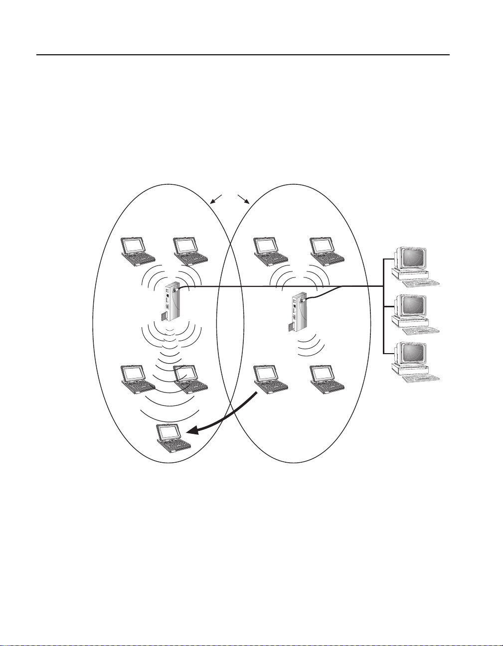
The AP enables wireless clients to move from the coverage area of one AP into the
coverage area of ano ther AP while maintaining LAN connectivity. This capabilit y is
called roaming. Figure 1-2 illustrates a wireles s clie nt roamin g from one AP coverag e
area to another. Each covera g e area is called a cell, where a cell is a si n g le AP and its
wireless clie n ts within a network of m u lt ip le APs.
Figure 1-2: Roaming
Coverage
Cell 1 Cell 2
Areas
PC
(Ap1)
PC
(Ap1)
(Ap1)
R
o
a
m
A
b
o
u
t
1
2
(Ap1)
PC
AP1
PC
PC
(Ap2)
Wireless
Client
R
o
a
m
A
b
o
u
t
1
2
PC
(Ap2)
AP2
PC
(Ap2)
PC
(Ap1)
LKG-8892-931-01
In Figure 1-2, Cell 1 and Cell 2 share overlapping areas of coverage. As a wireless
client moves f rom Ce ll 2 to Cell 1, the necessary network information is pas sed from
AP2 to AP1.
When a wireless clien t (s uch as the laptop computer in Figure 1-2) approaches the
boundary of a coverage area , the wirele ss clie nt sear ches for a new AP that provi de s a
better quality signal, resulting in more reliable data throughput.
1-6 Introducing RoamAbout Access Point
Page 23

AP to AP Configuration
You can connect two separa te LANs over a wireless link by configuri ng two
RoamAbout Access Points to communicate with each other. This is called a
LAN-to-LAN connection.
Figure 1-3 shows t wo APs in different building s using an outdoor antenna to connect
the LANs in those buil d ings.
Figure 1-3: Bui ld i ng- to-Building C onfiguration
AP to AP Configuration
R
o
a
m
A
b
o
u
t
1
2
R
o
a
m
A
b
o
u
t
1
2
2844-01-03
You can also configure APs to con nect two LANs in the same building.
Contact your Ca bletr on sal es rep resenta ti ve or vis it the RoamAbou t web si te for mo re
information about the optional outdoor ante nna kits.
Introducing RoamAbout Access Point 1-7
Page 24

Bridging Services
Bridging Services
The AP provides the following bridging services:
• Store-and-forward capability
The AP receives, checks, and transmits frames to other LA N s, enabling the
configuration of extended LANs.
• Frame filtering based on address
Using the address database and the source and destination addre sses from
incoming frames, the AP isola tes the traff ic that should not be allowed on other
LANs. This action reduce s the total data traffic on an extended LAN by not
forwarding the packets that have local destinati on addres ses or pa ckets tha t are not
allowed to be forwarded. This increases bandwidth efficiency.
• Data Link layer relay
The AP operates at th e Data Link layer of the Open Syste m Interconnec tion (OSI)
model. Operation at this layer mak es the AP transparent to the protocols that use
the LAN connectivity service. This protocol transparency is a key factor in the
extended LAN service.
• Dynamic address learning
The forwarding and tr ans lating process module automatically adds new source
addresses t o t he a ddress da tabase whi le t he AP is op erati ng. T his reve rse lear ning
of the address and port as sociation allows automatic network configurati on
without prior downline loading of configuration data to the AP. Note that the
address learn ing is protocol and management entity independent.
How long an address remains in the database is determined by an Aging Timer
that meas ures ho w m uch t ime has ela psed sin ce d ata was la st address ed to o r f rom
a particular node. If the timer lapses without an y traffic, the node’s address is
removed from the database.
• LAN-to-LAN Bridge mode
LAN-to-LAN mode is used to co nfigure th e AP to co mmunicate with another AP .
In LAN-to-LAN mode, the AP learns addresses from both the wireless network
and the wired Ethernet LAN. The AP filters packets based on their destination
address and forward s all packets with unknown address es. The default Aging
Timer interval is 2 minutes.
• Workgroup Bridge mode
Workgroup Bridge mode (the de fault mode) is used to configure the AP to
communicate with wireless clients. In Workgroup Bridge mode, the AP learns
addresses only from the wir eless side of the network. The AP only forwards
packets to multicast addresses, broadca st addresses, and known addresses on the
wireless LAN. The default Aging Timer interval is 32 minutes.
1-8 Introducing RoamAbout Access Point
Page 25

Configuration Tools
You can configure the AP using these tools:
• RoamAbout Access Point Console Port
• RoamAbout Access Point Manager
• clearVISN and Network Management Stations (NMS)
Console Port
The AP has a l ocal consol e port that enable s you to c onfigure a nd manage the AP using
a console port device (a terminal or personal computer running te rmi nal emulation
software). The device needs to be directly connected to the AP console port.
RoamAbout Access Point Manager
The RoamAbout Acc ess Point Manager is included in the RoamAbo ut Access Point
kit. You install the AP Manager on a Windows 95, Windows 98, or Windows NT
system.
The AP Manager can be used as a setup/ configuration tool for ne w APs and as a
management to ol to as sist the ongoing management and support of RoamAbout
wireless LANs. The AP Manager can manage multiple APs simultaneously.
Configuration Tools
The AP Manager has the following fea tures:
• Ability to manage multiple APs remotely, including changing parameters on
multiple APs in a wireless network with a single command.
• Ability to view AP parameters, such as AP statist ics, AP firmware version
number, MAC addresses, amount of memory, and card type.
• Integrity che cking for many wireless pa ram eter changes. This warns the user if a
common wireless network management mistake is about to be made, or if the
operation requested is unusual and usually not recommended.
• Integrity checking of an existing wireless network configuration for co nsistent
settings and common management errors.
• Improved wireless network performance through easy packet fil tering and
recommended filter settings.
• Integrated with a B ootP/ TFTP applic ation for s imple AP fi rmware upgrade s, also
called flash upgrades.
• Support for 802.11 radio technology as well as the earlier versions of the
RoamAbout Direct Sequence (DS) and Frequency Hopping (FH) products.
Introducing RoamAbout Access Point 1-9
Page 26

Configuration Tools
Other Management Tools
The AP supports the Simple Network Management Protocol (SNMP) through any
standard Network Mana gement Station (NMS) that supports SNMP. The SNMP
management capability enables you to manage standard SNMP MIB characteristics,
such as protocol filtering and address filtering.
To manage the AP with an NMS system, you must configure the AP with a valid IP
address, as de scribed in “Configuring the AP for SNMP Management” on page 4-16.
The management systems use MIB objects to manage the AP. The AP supports the
following MIB objects:
• MIB II (RFC–1213)
• IETF Bridge MIB (RFC–1493)
• Ethernet MIB (RFC–13 98)
• DEC ELAN Vendor MIB
• HUB PCOM MIB
• RoamAbout Access Point MIB
• RMON MIB (RFC-1757)
• 802.11 MIB
For details on the management features of each MIB, consult your NMS
documentation.
The Cabletron clearVISN system also supports the AP.
The AP Manager and console port do not support RMON. To set RMON
parameters and the multicast limiting rat e value, you need an NMS system or
clearVISN.
1-10 Introducing Roam About Access Point
NOTE
Page 27

Optional Antennas
When the AP is configured to support wireless clients, you may need the Range
Extender antenna to improve signa l quality when the PC Card in the AP is shielded.
In a LAN-to-LAN confi gura tion, y ou may need to ins tall outdoor ant ennas, espe ciall y
when the APs are located in separate buildings.
Range Extender Antenna
The RoamAbout PC Card in the AP has two integrated antennas tha t perform best in
an open environment with as few obstacles as possibl e. Use the Range Extender
Antenna (Figure 1-4) to ensure optimal transmission and reception quality for
situations where the integr ated antennas are shielded, such as:
• The PC Card is clo se to m e tal surfaces.
• The AP is installed in a hidden location, e.g. unde r a desk or ins ide a cabinet.
• Objects shield the PC Card.
You can co nnect the Range Exte nder anten na t o the PC Car d b y ins ertin g t he con nector
into the socket on the extende d side of the PC card. To protect th e socket from dust, it
is shielded with a cap. Remove this cap before you connect the antenna.
Optional Antennas
The Range E xtender a ntenna h as a moun ting b racket and a base f or vert ical posi tioning
that allo ws you to pl ac e the ante nna on top o f a ta ble or fil ing cabine t, or han g it on the
wall or ceiling.
NOTE
Many computer monit ors support a degauss option. The ele ctromagnetic
discharge that may occur when dega us sing the monitor may cause damage to the
antenna. To a void d amage , do no t place t he Range Ext ender Ante nna on t op of, or
too close to, a moni tor.
Introducing RoamAbo ut Access Point 1-11
Page 28

Optional Antennas
Figure 1-4: Ra ng e Ex te nder Antenna
Outdoor Antenna Kit
The RoamAbout outdoor antenna kit allows you to co nnect multiple buildings or
LANs via a wireless outdoor point-to-point link. The kit provides a selection of
high-gain, low-noise antennas and components.
Refer to the RoamAbout 802.11 Outdoor Antenna Installation Guide or the
RoamAbout web site for more information.
1-12 Introducing Roam About Access Point
Page 29

Chapter 2
Preparing for Installation
Before installing the AP, you must complete the following tasks:
• Unpack the AP and check the contents of the shipment.
• Selec t the lo cation to in s t al l th e AP.
• Review the site requirements.
Unpacking and Checking the Contents of the Shipment
Unpack and check the shipment for damage or missing parts. The shipment includes:
• RoamAbout Access Point
• Power supply
• RoamAbout Access Point Manager software on diskettes.
Optionally, you could also have these kits:
• RoamAbout PC Cards for wireless clients
• Range Extender Antenna
• Outdoor antenna ki t (building-to-building)
If any item is damaged or miss ing, immediately notify th e delivery agent and your
sales representative.
Preparing for Install ation 2-1
Page 30

Selecting the Location
Selectin g the L oc ation
If the AP is not installed in a MultiSwitch 900 or DEChub 90, you ca n mount the AP
on a wall, ceiling, or cubicle partition.
Depending on your confi guration, choose the locat ion to install the AP based on the
following gui delines.
For an AP to wireless client conf iguration:
• The size of the coverag e are a (in open air) is determined by the type of PC Card
in the AP and wireless client(s). The RoamAbout PC Card has an effective range
of up to a 550-ft. ra dius area (in an open environment). If using a card other th an
the RoamAbout PC Car d in wireles s clients , refer to tha t card’s d ocumentatio n for
information about allowable distances.
• Centrally lo ca te the AP wi th i n th e group o f w ir e less clie n ts to have al l w ir e less
clients with in the AP’s cove rage area. If permanent obstr uctions pr event you fro m
centrally mount ing the AP, mount it as high as possible. Figure 2-1 shows an
example of a centrally located, standalone AP.
• Minimize obstructions, such as walls (espec ially those made of steel rei nforced
concrete or masonry), between the AP and its wireless clients . Obstructions can
reduce the effective range of the radio transmission s from the PC Cards.
• If it is necessary to install the AP in an obstructed location, use the optional range
extender antenna, as described in “Optional Antennas” on page 1-11.
• If using multiple APs in the same wireless network, make sure that they have
overlapping coverage areas. You many need to adjust the placement of the APs
after the initial install ation to obtain the best signal quality and coverage.
For a LAN-to-LAN configurati on:
• If using an outdoor antenna, make sure that the AP and the outdoo r antenna use
the same groundin g system, as described in the RoamAbout 802.11 Outdoor
Antenna Inst allation Guide.
• If not using an antenna, the APs should be within 500 feet of each other; less if
there are obstructions.
2-2 Preparing for Inst allation
Page 31

Figure 2-1: M oun t in g t he A P in a Ce ntra l Location
R
o
a
m
A
b
o
u
t
1
2
Selecting the Location
LKG-8805-931-01
Preparing for Installation 2-3
Page 32

Reviewing the Site Requirements
Reviewing th e Site Requirements
Review the following to ensure that all site pre paration tasks were completed.
Hardware Requirements
• Ensure that the Ethernet LAN is in place and operable.
• If you are installing the AP in a standalone configuration, locate the Ethernet
interface device (for example, a ThinWire segment, DECconnect faceplate, or
other appropriate network device) to which to connect the AP. Otherwise, if you
are installing the AP in a MultiSwitch 900 or DEChub 90, ensure that the device
is installe d and operable.
• If you are installing the AP in a standalone configuration, ensure that an
appropriate ac power source is within 1.6 m (5.5 ft) of the AP.
• Ensure that a P C to in stal l the R oamAbout Acce ss P oint Ma nagemen t softwar e or
a console port device (a terminal or PC with terminal emulation software) is
available at the site for configuring the AP.
• Ensure that PC Cards are obtained for each wireless client.
• Ensure th a t th e location can accom mo d at e th e p hy sical size of th e A P , as
described in the following table.
Table 2-1: AP Physical Specifications
Parameter Value
Width 3.18 cm (1.25 in)
Height 27.31 cm (10.75 in)
Depth 13.34 cm (5.25 in)
Weight 0.68 kg (1.5 lb)
2-4 Preparing for Inst allation
Page 33

Electrical and Environmental Requirements
Ensure that the environmental and electrical requirements are within the ranges
described in the following tables.
Table 2-2: Environmental Specifications
Parameter Description
Operating Envi ronment
Reviewing the Site Requirements
Temperature
1
5°C to 50°C (41°F to 122°F)
Maximum rate of change 20°C/h (36°F/h)
Relative humidity 10% to 95% (noncondensi ng)
Wet-bulb temp er ature 32°C (90°F)
Altitude Sea level to 2.4 km (8000 ft)
Air flow Convection cooled
Nonoperating Environment
Temperature –40°C to 66°C (–40°F to 151°F)
Relative humidity Up to 95% (noncondensing)
Altitude Up to 4.9 km (16,000 ft)
Certifications CE, CSA, FCC, TÜV , UL, VCCI
1. F or sit es ab ove 49 00 m (16 ,000 ft), decre ase t he oper ati ng tempe ratur e sp ecific ati on by
1.8
°C for each 1000 m or 3.2°F for each 3200 ft.
Preparing for Installation 2-5
Page 34

Reviewing the Site Requirements
Table 2-3: Electrical Specifications
Voltage Current (Amperes) Power (Watts)
+5.0 V 1.2 A 6.0 W
Table 2-4: AP Power Supply Specifications
Parameter Value
Input voltage 100 Vac to 240 V ac
Current at 120 V 0.25 A
Frequency 50 Hz to 60 Hz
Power consumption 16 W
Output voltage 5.1 Vdc
Output current (maxi mum) 1.8 A
Table 2-5: AP Acoustical Specifications
Acoustics — Declared values per ISO 9296 and ISO 7779
Product
RoamAbout Access Point No acoustic noise No acoustic noise
Schallemi ssionswerte — Werteangaben nach ISO 9296 und
ISO 7779/DIN EN27779
Produkt
RoamAbout Access Point keine meßbaren
2-6 Preparing for Inst allation
Sound Power Level L
WAd , B
Sound Pressure Level
L
pAm , dBA
(bystander positions)
Idle/Opera te Idle/Operate
Schalleistungspegel
L
WAd , B
Schalldruckpegel L
pAm , dBA
(Zuschauerpositionen)
Leerlauf/Betrieb Leerlauf/Betrieb
keine meßbaren
Schallemissionen
Schallemiss ionen
Page 35

Cabling Requirements
For a standalone co nfigur ation only: E nsure that you have th e appro priate t ypes and
lengths of cable for connecting the AP to the wired Ether net. For a 10BaseT
connection, u se a BN2 6K cable. For a Thi nWire conne ction, yo u need a BC1 6M cable,
T-connector (H8223-00), and 50-ohm terminator (H8225-00).
If you are using the console port:
• For standalone and DEChub 90 configurations: Ensure that y ou have t wo 9-pin
DECconnect adapters (H8571-J) and an MMJ DECconnect BC16E cable for
connecting the console port device to the AP.
• For MultiSwit ch 90 0 co nfigur ations : Ensure t hat yo u ha ve a 9 -pin DECconnect
adapter (H8571-J) and an MMJ DECconnect BN24H cable for connecting the
console port device to the MultiSwitch 900. If your local co nsole port device is a
PC running termina l emulation software, you can use a 9-pin, D-Sub
(PC-compatible) serial (null modem) cable.
Refer to Table 3-1 on page 3-13 for a list of console port cable part numbers.
Refer to Appendix A for connector, cable and adapter pinout info rmation.
Reviewing the Site Requirements
NOTE
Preparing for Installation 2-7
Page 36

Page 37

Chapter 3
Installing the RoamAbout Access Point
This chapt er provide s a step-b y-ste p procedur e to instal l the Roa mAbout Acces s Point .
Before installing the AP, ensure that all the procedures in Chapter 2 are completed.
Installi ng the AP involves the following tasks :
• Insta ll in g th e P C Car d in to the AP
• Installing the AP in a standalone configuration, or in a MultiSwitch 900 or
DEChub 90
• Verifying the operation of the AP
• Connecting a device to the console port (if not usi ng the AP Manager)
• Installing the RoamAbout Access Point Manager
• Setting the AP pa r ameters
• Verifying wireless communication
Installing the RoamAbout Access Point 3-1
Page 38

Installing the PC Card
Insta lli n g the PC Card
To install the PC Card, do the following:
Step Action
1 With t he logo on the PC Card facing th e same di rection as the AP’ s BNC
connector, partially ins er t the card into the PC Card slot.
Access Point
R
o
a
m
A
b
o
u
t
BNC
Connector
1
2
PC Card
2 Gently push the c ard into t he slot until i t is fi rmly seated. You will sense
a slight resistance as you insert the card. When properly inserted, the
card protrudes approximately 1-1/2 inches from the AP.
3-2 Installing the RoamAbout Access Point
Logo
2844_01_04
Page 39

Installing the AP into a MultiSwitch 900 or DEChub 90
Installing the AP into a MultiSwitch 900 or DEChub 90
This section describes how to install the AP in a MultiSwitch 900 or DEChub 90.
Removing the Back Cover
If there is a cover on the back of the AP, you must remove it before inserting the AP
into the backpl ane . P erform the following steps to remov e the back cover:
Step Action
1 Lift up the latch on the back cover by inserting a flat-blad e screwdriver
into the top mounting hole.
LKG-6722-921-01
2 With the latch up, pull the top of the back cover away, pivoting at the
bottom of the AP.
Installing the RoamAbout Access Point 3-3
Page 40

Installing the AP into a MultiSwitch 900 or DEChub 90
Seating the AP in the MultiSwitch 900 or DEChub 90
You can install the AP in the MultiSwitch 900 or DEChub 90 without turning off
power. Seating the AP initiates the power-up sequence. However, when installing the
AP into a DEChub 90, connect the console port device to the console port before
applying power to the AP.
Perform the following steps to install the AP in the MultiS witch 900 or DEChub 90.
Step Action
1 Place the AP’s mounting tab into the first mounting slot on the
MultiSwitch 900 or DEChub 90.
2 Pivot the AP on the mounting tab and align the connectors.
3 Firmly push the AP onto the backp lane connec tors until the rele ase lever
clicks .
4 Press down on the release lever to ensure that it is locked.
Release Lever
Clicks when
Module is
Hub Manager
Status Display
MultiSwitch 900
Seated.
VNswitch 900G
VNswitch 900GV
V
DEChub 90
VNswitch 900G
V
Mounting Tab
LKG-9453-941-01
5 Perform the appropriate steps in “Installing the AP” on page 3-5.
3-4 Installing the RoamAbout Access Point
Page 41

Insta lli n g the AP
Perform the following procedure to install the AP as a sta ndalone module. Also, you
may need to perform step s 4 and 5 after installing the AP in a DECHub 90 or
MultiSwitch 900.
Step Action
1 Place the AP in the previously defined location. Site requirements are
2 Connect the AP to the wired network using either the 10BaseT or
Installing the AP
defined in Chapter 2.
ThinWire connector, as follows:
To Connect to ThinWire Network –– Connec t a Th inWi re cable,
T-connector, and terminator to the BNC connector on the AP. Note tha t
instead of a terminator, the other side of the T-connector can be cabled
to another device in the LAN.
50-ohm
Terminator
Access Point
R
o
a
m
A
b
o
u
t
1
2
T-Connector
LKG-8685-931-01
Installing the RoamAbout Access Point 3-5
Page 42

Installing the AP
Step Action
To connect to a 10BaseT Network –– Connect the 10BaseT cable to
the 10BaseT Ethernet connector.
Access Point
R
o
a
m
A
b
o
u
t
1
2
3 Connect the other end of the ThinWire cable or 10BaseT cable to an
active Ethernet o u tlet, such as a DECconnect faceplate o r o t her
appropriate network dev ice.
3-6 Installing the RoamAbout Access Point
LKG-8686-931-01
Page 43

Installing the AP
Step Action
4 To configure the AP, you need the RoamAbout Access Point Manag er
(see “Installing the RoamAbout Access Point Manager” on page 3-15)
or a console device.
To use a console device, connect a 9-pin serial cable to the AP’s 9-pin,
D-Sub, PC-compatible serial port.
Note: The pinouts for the AP’s local console connector are list ed in
Appendix A.
Access Point
R
o
a
m
A
b
o
u
t
1
2
LKG-8804-931-01
Installing the RoamAbout Access Point 3-7
Page 44

Installing the AP
Step Action
5 If using an antenna (outdoor or range extender antenna), install the
antenna cable to the PC Card. The following figure shows the optional
range extender antenna.
Access Point
Range
Extender
Antenna
(Optional)
R
o
a
m
A
b
o
u
t
1
2
3-8 Installing the RoamAbout Access Point
2848-01-02
Page 45

Installing the AP
Step Action
6 Connect the AP’s power supply cable to the power connector on the
back panel of the AP.
If using an outdoor antenna, make sure that the AP and the outdoor
antenna use the same grounding system, as described in the RoamAbout
802.11 Outdoor Antenna Installation Guide.
7 Connect the power supply to an AC outlet to turn on the AP.
LKG-8673-931-01
8 Go to “Verifying t h e Operation of the RoamAbout Access Point” on
page 3-10.
Installing the RoamAbout Access Point 3-9
Page 46

Verifying the Operation of the RoamAbout Access Point
Verifying the Operation of the RoamAbout Access Point
The AP runs a series of self-te sts on power-up and reports status using its LEDs.
When power-up begins, the following occurs:
Stage Description
1 The firmware begins running diagnostics, initializes minimal hardware,
then sequentially turns LEDs 2 through 6 on and off.
2 After LED 6 turns on and then turns of f, the firmware completes its
diagnostics and hardware initializat ion. During this portion of the
diagnostics and hardware initializa tion, LEDs 2 through 7 flash on and
then off.
3 The diagnos tics th en che cks t o s ee if the PC C ard is prop erl y in ser ted i n
the AP. If a card is present, the PC Card Pres e n t LED lights.
The diagnostics take approximately 10 seconds to complete after power-up. Upon
successful completion of the diagnosti cs , the LED pattern shown in Figure 3-1 is
displayed.
If the AP fails to display the proper LED pattern, verify that you have correctly
installed the AP. If the AP still fails to display the LED pattern, refer to Chapter 5.
3-10 Installing the RoamAbout Access Point
Page 47

Verifying the Operation of the RoamAbout Access Point
Figure 3-1: Normal LED Pattern
Access Point
1
2
3
R
o
a
m
A
b
ou
t
4
5
6
7
1
2
LKG-10067-931-01
Item LED Name Operational State
1 Power OK On = power is okay
2 Module OK On = self-test passed
3 Wire d LAN Acti vity Blinking = network connection
4 Bridge State On = lights after 30 seconds indicating
that the AP is forwarding packets
5 AP Saturated Off
6 Wire les s LAN Act ivity Blinking
7 PC Card Present On = PC Card is installed
Installing the RoamAbout Access Point 3-11
Page 48

Connecting a Device to the Console Port
Connecting a Device to the Console Port
The console port on the AP allows you to access and set AP parameters. If the AP is
installe d on the MultiSwit ch 900, you need to connect the device to the hub’s console
port.
You do not need to use the console port if you plan to manage the AP with the AP
Manager.
Console Port Signaling Standards
Signals from the MultiSwitch 900 console port and fr om the standalone console port
conform to the EIA-232D signaling standard at 9600 bau d only. To the user, the port
appears as a data terminal equipment (DTE) device .
Connecting to the Console Port
The console port on the AP standalone unit or the MultiSwitch 900 can be connected
to a console port device (a terminal or personal computer) by using the cables and
adapters listed in Table 3-1 and shown in Figure 3-2. Refer to Appendix A for the
console port connector, cable and adapter pinouts.
When installing the AP into a DEChub 90, you must connect the conso le port
device to the console port before applying power to the AP.
To connect a device to the AP console port, do the following:
• Ensure that the transmit and receive baud rates on the console port device are set
to 9600 baud only.
• Connect the console port device to the console port connector on either the AP
front-panel serial port or the MultiSwitch 900 console port.
3-12 Installing the RoamAbout Access Point
NOTE
Page 49

Table 3-1: Con sole Port Cabling
Connecting a Device to the Console Port
Connecting
to a...
If the console
port device is
a...
Standalone AP or
DEChub 90
PC with a 9-pin
D-Sub
communications port
and terminal
emulation
Terminal with a
25-pin D-Sub
connector
Terminal with a
6-pin MMJ
connector
MultiSwitch 900 PC with a 9-pin
D-Sub
communications port
and terminal
emulation
Terminal with a
25-pin D-Sub
connector
Then use
this c a ble.. .
BC16E-xx
1
any std. PC
compatible
9-pin serial
cable.
BC16E-xx
BC16E-xx
BN24H-xx
BN24H-xx
1
1
1
1
With these
adapters...
or
H8571-J (qty = 2)
H8575-A,
H8571-J
H8571-J
H8571-J
H8575-A
2
2
2
2
Terminal with a
6-pin MMJ
connector
1. xx indicates cable length in meters.
2. The AP requires an H8571-J also.
BN24H-xx
Installing the RoamAbout Access Point 3-13
1
H8575-A
Page 50

Connecting a Device to the Console Port
Figure 3-2: Con sol e Po rt C abl in g
3
1
H8571-J
H8575-A
BN24H
Item Description
1 MultiSwitc h 900 console port
2 AP console port
3 Console port device
Access Point
3
1
2
H8571-J
2
R
o
a
m
A
b
o
u
t
H8575-A
BC16E
3-14 Installing the RoamAbout Access Point
Page 51

Installing the RoamAbout Access Point Manager
Installing the RoamAbout Access Point Manager
Before installing the Roa mAbout Access Point Manager, first select a computer that
meets these requirements:
• Operating system is Windows 95, Windows 98 and Windows NT V4.0 or later.
• The computer is connect ed to the AP’s wired or wireless LAN. However, a
computer connected on the wireless LAN can not upgrade the firmware on its
associated AP.
To install the RoamAbout Access Point Manager, insert the floppy disk (disk 1 of 2)
in the PC and run A:SETUP (this can be done from the Windows Explorer, DOS
prompt or the Run option from the Start button). Follow the Setup instru ctions.
If you have a previous version of the AP Manager, instal l the AP Manager on the same
computer. The setup process automatically upgrades the existing software and keeps
your existing configuration files.
You can access the AP Manager through the MultiChassis Manager (MCM)
component (V6.2 or lat er) of the clearVISN system. Simply right click on the device
and select the RoamAbout Configur ator menu item. Howeve r, the AP Ma nager defa ult
directory has cha nged from an earlier default setting. Therefore, you may need to
change the \Progra m Fil es\clearVIS\hubwatch\hubwatch.ini file as follows:
Find th ese lines:
[Applications]
RoamAbout Confi gu r at or=c:\roam abt\confi g\config.exe $I $C
Change them to:
[Applications]
RoamAbout Configurator=c:\Program Files\RoamAbout\Manager\Rmabt_APManager.exe $I $C
NOTE
To manage an AP with the AP Manager, you must assign the AP an IP address.
You can use the AP Mana ger to loa d the IP ad dress, as desc ribed in “Conf igur ing
the AP for SNMP Management” on page 4-16.
Installing the RoamAbout Access Point 3-15
Page 52

Setting the AP Parameters
Setting the AP Parameters
The AP is shipped with the following default values:
• IP Address: 0.0.0.0
• IEEE Power Management enabled
• Secure Access enabled
• Encryption dis abled
• Workgroup bridge mode
• Station name : RoamAbout AP
• Wireless Network Name : RoamAbout Default Network Name
• AP Density: Low
• RTS Threshold: 2347 (this value equals an OFF state)
• Trans m i t Rate: Au to Ra te Selec t
• Limi t multica s t tr a f f ic to 100Kb/sec
Refer to Chapter 4 to change these and other parameters . Also refer to “C onfiguring
the AP for SNMP Management” on page 4-16 for instructions to specify the AP’s
SNMP management parameters.
To configure the AP for LAN-to-LAN, refer to “Configuring the AP for
LAN-to-LAN” on page 4-15.
Verifying Wireless Communication
To verify tha t the AP can com municat e with its wirel ess cl ients or anothe r AP, u se the
AP Manager Point -to-Point diagn ostic test as follows. To use thi s test, the AP fi rmware
must be V3.4 or later and the AP Manager must be V3.4 or lat er.
1) Select the AP in the Mana ged List field.
2) Click Integrity in the menu bar.
3) Select Point-to-Point Diagnostics. For more inf ormation, press F1 on the
keyboard for the onli ne help topic.
You can al so use the RoamAbout Client Util ity to test the communications path from
a wireless clien t to th e A P . T h e cl ie nt utility is describ e d in th e RoamAbout IEEE
DS/PC Card and ISA Adapter Card User’s Guide.
3-16 Installing the RoamAbout Access Point
Page 53

Chapter 4
Configuring the RoamAbout Access Point
This chapter describes how to configure the AP parameters.
Depending on the configu ration of your wirel ess network, you may need to change the
default settings of various parameters.
Refer to “Configu ring the AP for SNMP Management” on page 4-16 to have the AP
managed by an SNMP Manager.
Configuring the RoamAb out Access Point 4-1
Page 54

Starting a Configuration Tool
Starting a Configuration Tool
To modify AP parameters after installing the AP, you need to use the RoamAbout
Access Point Manager or a device connected to the consol e port. The following
sections desc ribe how to start each tool.
RoamAbout Access Point Manager
If you have installed the RoamAbout Access P oint Manager o n a computer, go to that
computer, click the Start button on the Windows desktop, and select:
Programs
The program starts with the following screen.
→RoamAbout→RoamAbout Access Point Manager
To manage APs from the AP Manager, you need to add the APs by selecting the
Setup/Add New Access Point button. First, you are prompted to add a new AP with
or without an IP address. If t he AP has an IP addre ss, selec t NO ; otherwis e, selec t YES
and fill in the r equired information.
When you first establish communications with the AP, you are prompted for some
general information and then prompted for your wireless pa rameters. It is highly
recommended that you change the Wireless Network Name from the default, as
described in “Wireless Parameters” on page 4-6.
4-2 Configuring the RoamAbout Access Point
Page 55

You can add all your APs within a wire less domain (defined by the same Wireless
Network Name) so that they show up in one Managed List for future changes. Before
you exit the AP Manager , make sure to save your Managed List file (you will be
prompted). If you are managi ng APs in multi ple doma ins (d ifferen t Wirele ss Net work
Names) you should save these APs in a separate file.
Press F1 on your keyboard while in any AP Manager window for information about
the parameters in that window.
Console Port Device
If using a d evice c onne cted to the AP co nsole port, y ou n eed t o acc ess the RoamAbout
Access Point Installation Menu to modify the AP parameters. Perform the following:
Step Action
1 Press Return a few times on the console port device until a menu
Starting a Configuration Tool
appears.
If the AP is connected to a DEChub 90 or is a standalone unit, the
RoamAbout Access Point Installation Menu appears.
Note: If the AP is insta lled in a DEChub 90, the AP must be powered of f
before connecting a cable to the console port.
2 If the AP is connect ed to t he MultiS witch 9 00 consol e port, choose Start
Redirect Mode in the MultiSwitch Installation Menu. Afterwards, enter
the AP slot number as shown in the following example.
Enter selection: 9
================================================
Enter the slot number for redirection (1-8): [n]
setup redirected to 3: RoamAbout Access Point
The initial installation menu allows you to display and modify the Acc es s Point
parameters. Use the Module-Specific Options menu item to display and modify the
wireless networking parameters.
To prevent other user s from acc essing the consol e port menu, choo se Enable/Disable
Console Password fro m the me nu and en able it. Then change the default SNMP
community string as described in “Configuring the AP for SNMP Mana gement” on
page 4-16. Afterwards, the console port will require users to enter the community
string before displaying the menu.
Configuring the RoamAbout Access Point 4-3
Page 56

Showing Current Settings
Showing Current Settings
You ca n di s p lay the settings th at the AP is cu r r en tly usin g .
Using the AP Manager, select the AP in the Managed List field and cli ck the various
buttons, s uch a s Wi re les s P ara met e rs, Operatin g Modes, IP Network Parameters,
and Hardware.
In the Wireless Parameters dialog, click the Advan ce d button to view all the wireless
parameters. If you see a Normal button instead of Advanced, the dialog is currently
displayin g all the wire less parameters. If you have changed any wire less parameters
and have not yet reset th e AP, the oper at ing (curre nt) setti ngs are displa yed on the le ft
and the settings that will take affec t after the next reset are on the right.
Using the console port, choose Show Current Settings to display the current AP
settings, as shown below.
=================================================================
RoamAbout Access Point,Wireless-to-Wired Bridge:HW=V1.0,RO=V1.4,SW=V4.
SysUpTime : 00:26:37 98 resets
SNMP Read/Write Community : public
Console Password : Disabled
SNMP Trap Addresses : Not Configured
In-Band Interface Hardware Address : 08-00-2B-A3-89-61
In-Band Interface IP Address : 16.20.40.156
In-Band Interface Subnet Mask : 255.0.0.0
In-Band Interface Default Gateway : Not Configured
Wired Ethernet MAC Address : 08-00-2B-A3-89-61
Wireless Ethernet MAC Address : 00-60-6D-92-00-FB
Wireless Network Adapter : RoamAbout IEEE 2.4 GHz DS
Adapter Revisions : Hardware 2.000 Firmware 3.01
Bridge Mode : Work Group
Upline Dump : DISABLED
Memory : 4194304 bytes
===================================================================
Press Return for Main Menu ...
n
4-4 Configuring the RoamAbout Access Point
Page 57

Showing Current Settings
To display the cur rent wirel ess sett ings , choo se Module-Specific Options then select
Show Wireless Configuration. If you have changed a wireless parameter and have
not yet reset the AP, the new setting is NOT reflected in this display. The following
example shows the dialog associated with this option.
====== ========= == ======== === ======== ========= == ======== =====
RoamAb out Acces s Point Wireless Conf iguration
Current Station Name : RoamAbout AP
Curren t Wireles s Network Name : RoamAb out Default Network Name
Current Secure Access : Enabled
Current Channel : 2.4220 GHz (802.11-3)
Current AP Density : Low
Current RTS Threshold : 2347
Curren t Transmi t Rate : Auto Rate Select
Current DTIM Period : 001
Press Return for Main Menu ...
Configuring the RoamAbout Access Point 4-5
Page 58

Wireless Parameters
Wireless Parameters
The wireless parameters affect how the AP communicates with wireless clients or
another AP.
To modify any wireless parameter using the AP Manager, sel ec t the AP in the
Managed List fie ld and clic k the Wi rele s s Pa ram ete rs button. T o see all the wireless
parameters, click the Advanced button.
To modify any wireless paramete r usi ng the console port, choose Module-Specific
Options then choose Set Wireless Configuration. To not change a value while in its
screen, press Return to go back to the previous menu.
The following sections describe the various wireless parameters.
To implement a change to one or more wirele ss parameters, you need to reset the
AP, as described in “Re setting the RoamAbout Access Point” on page 4-14.
NOTE
Channel
The channel sets the cente r frequency of the AP. In a LAN-to-LAN confi gurati on, the
APs need to be s et to the s ame chann el. In a wir eless cl ient co nfigurat ion with mult iple
APs, adjacen t APs s hould b e se t t o d ifferen t chan nels tha t are a t lea st 5 channe ls apart.
For example, in a configur at ion wit h 3 APs, set the chann els to 1, 6, and 11. Note that
some countri es only suppor t a limit ed number of channels . T he AP does not a ll ow you
to set channels outside your country’s band.
Wireless clients with RoamAbout PC Cards automatically switch to the AP’s channel
when roaming between APs in a wireless network.
Wireless Network Name
The Wireless Network Name is the network name for your AP. All APs on the same
LAN must be set with the same Wireless Network Name.
If the AP is configured to communicate with wireless clients and the Secure Access
parameter is ena bled, each c lient mus t be conf igur ed with the same Wire less Ne twork
Name. If Secure Access is not enabl ed, clients can be configured with the AP’s
wire less net work na me, ANY (all uppercase), or keep the Wirele ss Network Name
field blank.
4-6 Configuring the RoamAbout Access Point
Page 59

Station Name
The Station Name is displayed when clients run the Client Utility. Select a name that
will help identify the location of the AP.
AP Density
The AP Density changes the sensitivity of the roaming client. When APs are placed
close together, you can change the AP Density to Medium or High to force clients to
roam sooner to a clos er AP. The defa ult value i s Low. Client s should be set t o the same
value as th e AP.
Transmit (Tx) Rate
The tran smit rate id entif ies th e pref erre d data tran smissio n spee d of the AP. The actua l
data transmission speed is subject to t he type of PC Card s at both ends of the wireless
link and the communications quality of the link.
By default , the PC Card automatic ally switche s to a lower rate when da ta transmiss ions
fail more than once. Transmissions at lower rates are usually more reliable.
Transmissions at higher rates do not cover the same distances as the lower data rates.
Shortly after completing the transmission, the PC Card returns to transmitting data at
the selected rate. This is called the auto-rate select feature.
Use a lower rate in networks where range is more important than speed, or network
response times are affected by numerous retransmissions . For example, set the
transmit rat e to a lo w rate when the communic at ions qua li ty i s low due to a l ow signa l
level. Se tting the transmit rate to a lower ra te prevents the PC Card f rom slowing
network response times by transmitting data uns uccessfully at a higher rate then
retransmitting at a lower rate.
Wireless Parameters
Use a fixed rate when performanc e slows down as a result of many retransmissions,
even though the devices show an excel lent radio connection. This situation ca n occur
when, for example, microwave ovens interfere with communication. A fixed rate
prevents the PC Card from sl owing network response time by retrans m itting at a
slower rate. In this enviro nment, trans mitting at 1 Mbit/s is not more useful than
transmitting at 2 Mbit/s.
The transmit rate you select does not affect the rece ive rate. For example, you can set
the transmit rate to 1 Mbit/s and still receive 2 Mbit/s data.
Configuring the RoamAbout Access Point 4-7
Page 60

Wireless Parameters
RTS Threshold
RTS Threshold, also known as medium reservation, specifies the packet size, where
messag es la rg er th an t he sp ecif i ed si ze mu st u se t he RTS /CTS ( Requ es t t o S end /Cl ear
to Send) protocol. The default value, 2347, eff ec tively turns off the RTS Threshol d.
In a wireless network, only one wireless device tr ans mits at a time. Each device can
sense transmis sions from other device s in its network that use the s ame frequency. This
behavior is referre d to as the Carrier Sense Multiple Access/Collision Avoidance
protocol (CSMA/ CA).
The RTS Threshold is useful when collisions frequently occur at the AP. This can be
caused when the AP and another d evice trans mit data to e ach other si multaneous ly. By
lowering the RTS Threshold on the AP:
• When a message is short er tha n t he RTS Thres hold, the AP tr ansmit s da ta when it
• When the m essage exceeds the threshold, the A P sends an RTS to the client (or
Lowering the RTS Threshold imposes additiona l network overhead that could
negativel y affect the throughput performance. Therefore, you should only lower the
RTS Threshold when the wireless network experiences frame collisions and lost
messages.
senses that the medium is free. The RTS/CTS protocol is not used.
AP in a LAN-to-LAN confi guration). The AP waits u ntil the device responds with
a CTS mes s ag e .
Medium Reserva tion on the client is useful for resolving a hidden stat ion problem,
where two or more clients cannot sense each other’s transmissions, causing frame
collisions and lost messages. This problem can occur with clients located at opposite
ends of the AP coverage area. If you have a hidden station proble m, move the clients
or AP so that the devices can sense each other’s transmissions, if possible. Otherwise,
set Mediu m Rese rvation on the Ro amAbout c lie nt to the Hidden Stations setting. For
a hidden station problem, change Medium Reservation on the client, not the AP.
4-8 Configuring the RoamAbout Access Point
Page 61

IEEE Power Management (DTIM Period)
Power Management c an extend bat tery life of clients by a llowing t he client to s leep for
short periods of tim e while the AP buffers messages for the client.
You may need to balance wireless performance versus battery-life. Power
Management c an impose a more active use of the wireless me dium , which might lead
to more frequent transmission delays, experienced as slower network response times
during file transfers.
With slower response times, the client may spend more ti me in operational mode
resulting in less effective power management. In such cases, disabling power
management on the cl ient might result in better throughput performance.
RoamAbout PC Cards with Station Firmware lower than V2.00, do NOT support
Power Management. Enabling Power Management for such cards can cause
unpredictable computer behavior and a loss of the network connection. To check the
Station Fir mwa re ve rsion, run the RoamAbout Client Utility, choose Diagnose Card
then choose the ta b Version In fo. If the s econdary fi rmware v ersion is les s than V2.0 ,
check the RoamAbout web site for available upgrades.
The AP supports IEEE Power Management. The DTIM (Delivery Traffic Indication
Message) inter v al value sets th e buffer i ng ti m e . F or ex a m p le , th e def a ult value of 1
corresponds to 100ms of sleep time. It is highly rec ommende d that you do not change
this value.
Wireless Parameters
Secure Access
When Secure Access is enabled, the AP denies access to wireless clients that do not
use the correct Wireless Network Name. When Secure Access is disabled, the AP
allows access to wireless clients that use ANY (all uppercase) as the Wireless Network
Name or have a blank Wireless Network Name.
Configuring the RoamAbout Access Point 4-9
Page 62

Setting Bridge Mode
Setting Bridge Mode
The optio ns are:
• Workgroup Mode configures the AP to communicate with wireless clients. This
is the def ault setting.
• LAN-to-LAN Mode configures the AP to communicate with another AP. The AP
to AP conf ig uration co n nects two LANs.
To configure an AP for LAN-to-LAN mode, you may need to change other parameters .
For the complete procedure, refer to “Configuring the AP for LAN-to-LAN” on page
4-15.
The bridge mode setting is available by clicking the Wireless Param eters button in
the AP Manager then clicking the Advanced button. In the console port menu, select
Module-Specific Options.
To implement thi s c hange, you ne e d to re set t he AP a s de scrib ed in “R esetti ng the
RoamAbout Access Point” on page 4-14.
NOTE
Setting Default Rate Limiting (Multicast Traffic)
By default, the AP is configured to limit multi ca st traffic to 100Kb/sec (5%).
You can enable or disable this parameter from the AP Manager or console port.
Disabling thi s parameter could ca use multicast traffic to use more net work bandwidth.
Should a broadcast s torm occur when this parameter is disabled, the multicast traffic
could cause a serious degradation of network performance.
You can change the value of the multicast traffi c limit from a Networ k Management
Station (NMS).
The Default Rate Limiting setting is available by clicking the Operating Modes
button in the AP Manager, or selecting the Module-Specific Options in the consol e
port menu.
4-10 Configuring the RoamAbout Access Point
Page 63

Setting Encryption
The Wired Equivale nt P rivacy (WEP) feature uses a specific ke y to enc r ypt all data
transmitted from the Access Point. However, it uses one of 4 keys to decode received
encrypted data. A wireless client without the correct encryption keys cannot receive
and decipher encrypted data from the Access Point. You can configure the AP to
communicate with clients that use WEP and clients that do not.
One versio n of the R oamAbout P C Ca rd i n the AP s upports t he 802. 11 standar d 40 -bit
encryption only. Another version supports both 40-bit and 128-bit encryption. The
standard 40-bit encryption uses a 5 character key (or 10 hexadecimal digits). The
128-bit encryption uses a 13 character key (or 26 hexadecimal digits).
A hexadecimal dig it key must start wit h 0x, which is not count ed in the number of
digits. For example, 0xABCDEF0123 is a valid 40-bit encryption hexadecimal
key (10 hex digits).
There are 4 positi ons, Key 1, Key 2, Key 3, and Key 4. The position of each key is
important, since the clients must enter the same key in the same position to
communicate with the AP.
Setting Encryption
NOTE
In the AP Manager, the Encryption setting is available by clicking the Encryption
button. When you open the Encryption window, press F1 on your keyb oard for specific
information on each field.
In the console port menu, select the Module-Specific Options. If you enable
Encryption, you must also enter at least one key and choos e a transmit key.
If you wish to prev ent any SNMP Manage r, includi ng the AP Manager , from changing
the Encryption parameters, select Set Exclude WEP SNMP from the Encryption
menu in the console port and enable it.
NOTE
If you enable/di sa ble Encryption or allow/disallow nonencrypted cli ents to
communicate wi th the AP , yo u ne ed t o res et t he AP as desc ribed in “Reset ti ng the
RoamAbout Access Point” on page 4-14. You do not need to re s et the AP to a dd,
delete, or modify keys.
Configuring the RoamAbout Access Point 4-11
Page 64

Setting RMON Values
Setting RMON Values
The AP supports four of the nine Re mote Ne twork Monit orin g MIB (RMON) gro ups:
Statistic s , History, Alarm, and Event. However, the settings for these groups can only
be accessed with an NMS system . T he console port and AP Manager can not change
or view the RMON group settings .
• Statistics - The Statistics group contains statistics measured by the probe for the
Wired LAN an d the Wireless LAN interfaces.
• History - The History group records periodic statis tical samples from a network
and sto r es th em for la te r retrieval.
• Alarm - The Alarm group periodically takes statis tical sample s from variab les in
the probe and compares them to prev ious ly configured threshold s. If the
monitored variable crosses a threshold, an ev ent is generated.
• Event - The Event group controls the generat ion and notification of events from
this device.
When the AP is initialized, two statistics groups are generated: one for the Wired
interface an d one for t he Wireless interface . Also, two History gr oups ar e generate d for
each interface: one with a short term polling period of thirty seconds and one with a
long term polli ng period of thirty minutes.
The AP has the following limits for the RMON MIB because of memory limitations:
• A maximum of six Statistics groups.
• A maximum of four History groups, each group allowi ng a maximum of fifty (50)
“buckets”, i.e., samples.
• A maximum of ten Alarm groups.
• A maximum of ten Event groups.
With an NMS sys tem, you c an re configure e ach gr oup. F or exa mple, y ou c ould assi gn
80 buckets each to the long and short term History groups assigned to the Wired
interface, and 20 buckets each to the long and short term History groups assigned to
the Wireless interface. This example does not exceed the maximum of 200 buckets.
4-12 Configuring the RoamAbout Access Point
Page 65

Checking the Configuration on Multiple APs
Checking the Configuration on Multiple APs
You can use the AP Manager to chec k the integrity of your APs’ configu ration. This
will insure that al l your APs (wit hin a domain) are c onfigured c orrectly. You can sel ect
to check the Wireless, Mode or Firmware integrity. Be fore running an integrity test,
click the Select All button under the list of APs to ensure that all the APs are checked.
Wireless IDs - Checks that all APs are configured with the same Wireless Network
Name, different sta tion name, same AP density setting, and the same RTS Threshold.
Modes - Checks that all APs are conf igured with the same operating modes, su ch as
rate limiting, upline dump, and bridge mode.
Firmware Revisions - Verifies that all APs have the same version of the firmware.
Configuring the RoamAbout Access Point 4-13
Page 66

Resetting the RoamAbout Access Point
Resetting the RoamAbout Access Point
There are two ways to reset the AP:
• Reset with Current Settings
This option reboots the AP but leaves the AP’s configur ed NVRAM parameters
at their current settings.
If you change any wireless confi guration parameter (Wireless Network Name,
Channel, Station Name, etc.), you must select this option to reset the AP.
From the AP Manager, sel ect Reset/Reload then select Reset with Current
Settings.
From a device attached to the console port, select Reset with Current Settings
from the Installation Menu.
Allow approxim ately 1 minute for the AP to reset and complete its self-test.
• Reset with Factory Defaults
This optio n reboots the AP, causing the AP’s configured NVRAM para meters to
be initialized to factory default values.
This action del etes all configuration settings and replaces them wit h factory
default values. All configuration settings will be lost, inclu ding the IP addre ss.
From the AP Manager, sel ect the AP from the Managed List field, cli ck the
Reset/Reload button, then click the Reset with Factory Defaults button.
From a device attached to the console port, select Reset with Factory Defaults
from the Installation Menu.
Allow approxim ately 1 minute for the AP to reset and complete its self-test.
4-14 Configuring the RoamAbout Access Point
Page 67

Configuring the AP for LAN-to-LAN
To configure two APs to communicate with each other in a LAN-to-LAN
configuration, perform the following tasks:
1) Get the wireless MAC address of the remote AP.
You can see the wireless address via the AP Manager or console device, as
described in “Sho wing Current Sett ing s” on page 4-4. T he wirel ess MAC add ress
is NOT the s ame as the wired MAC address printed on the front of the AP.
2) Set the Bridge Mode to LAN-to-LAN, as described in “Set ting Bridge Mode” on
page 4-10.
3) Make sure that the APs use the same channel. To change the AP channel, see
“Wireless Parameters” on page 4-6.
4) Set the Transmit (TX) Rate to Auto Select, which is the default setting. See
“Wireless Para meters” on page 4-6 to change the Transmit Rate.
5) Perform this procedur e on the other AP.
The following AP parameter s ar e not used in this mode:
• Wireless Network Name
Configuring the AP for LAN-to-LAN
• Secure Access
• AP Density
• Power Management (DTIM Period)
Configuring the RoamAbout Access Point 4-15
Page 68

Configuring the AP for SNMP Management
Configuring the AP for SNMP Management
To enable SNMP management for the AP, use the AP Manager or console port to
perform the foll owing tasks:
• Set the in-band int erfa ce IP address of the AP.
• Set the in-band int erfa ce default gateway address.
• Optionally set the SNMP read/write community n ame (default is “public” ) .
• Optio nally ad d S N M P tr a p ad d r esses.
Set In-Band Interf ace Addr ess es
To perform SNMP management on the AP, you must assign it an IP address, alon g
with a subnet mask and default gateway. If there is a BootP/ TFTP server on the
network configured with the MAC address of the AP, the AP will get an IP addre ss
from it.
To enter the AP’s IP address, subnet mask and default gateway using the AP
Manager:
1) Click the Setup/Add New Access Point button.
2) In the popup dialog, select Yes to load a new IP address.
3) Enter the AP’s MAC address, IP address, subnet mask, and default gateway.
4) Click OK to reset the AP. Allow approximately 1 minute for the AP to reset and
complete its self-test, then click OK.
To modify an existing AP’s subnet mask and default gateway using the AP
Manager:
1) Select the AP in the Mana ged List field.
2) Click the IP Network Parameters button.
3) Enter the subnet mask and default gateway.
4-16 Configuring the RoamAbout Access Point
Page 69

Configuring the AP for SNMP Management
To chang e or d elet e the A cce s s Poi nt ’s curr ent IP ad dre ss usi ng the A P M ana ge r:
1) Select the Access Point in the managed lis t .
2) Click the IP Network Para me ters button.
3) Set the Address State to Volatile then click OK.
4) In the main AP Manage r window, clic k the Rese t/Reload button. The n click Re set
with Current Settings. This will set the IP address back to 0.0.0.0. The Access
Point is no longer manageable by the AP Manager.
5) Use the Setup/Add New Access Point butt on to give the Access Point a new I P
address and add it back to the list of managed Access Points.
To enter the AP’s IP address, subnet mask, and default gateway using the console
port:
1) At the RoamAbout Ins tallat ion Menu, choos e Set In-Band Interface IP Address.
2) Enter the IP a ddress, subnet mask, and default gateway. You do not need to res et
the AP.
Configuring the RoamAbout Access Point 4-17
Page 70

Configuring the AP for SNMP Management
Set SNMP Read/Write Community
To perform SNMP mana gement on the AP, you mus t assign i t a community na me. The
format for a community name is a string con sisting of 4 to 31 printable ASCII
characters. Thi s community name can be used by SNMP managers for read/write
access control. The default community name is public.
If you use an SNMP read/wri te community name other than public, you can also
prevent other users from accessing the console port menu. To require users to
enter the community string before displaying the menu, choose Enable/Disable
Console Password fro m the cons ole port menu and enable it.
To enter a com munity na me for t h e AP us i ng the A P M a na g er:
1) Select the AP in the Mana ged List field.
2) Click on the Options menu and select Community Strings.
3) Enter the communit y name (4 to 31 pri ntable ASCII charac ters ) in the dialog box
and click OK. The change is sent to the AP. The AP Manager also changes its
inter n al c o mmunity s tr i ng to matc h the AP.
NOTE
If the AP has a community n ame, the AP Mana ger and any othe r SNMP Manager must
have the correct community name associated with th e AP; otherwise, the tool will be
unable to make any change s to the AP.
To enter a com munity na me for t h e AP us i ng the co n s ol e p o rt:
1) At the RoamAbout Installation Menu, choose Set SNMP Read/Write
Community.
2) Enter the community name (4 to 31 printable ASCII characters).
4-18 Configuring the RoamAbout Access Point
Page 71

Set SNMP Trap Addresses
To have the AP send SNMP traps , you need to enter t he IP address of the device where
the trap is to be sent. A trap is a defined event or co ndition detected by the Roa mAbout
Access P o in t SNMP agent.
To enter an SNMP trap address using the console port:
1) At the RoamAbout Installation Menu, choose Add SNMP Trap Addresses.
2) Enter the S N M P tr ap ad d res s.
Note: To not change the e x isting value, press Ret urn to go back to the previous
menu.
To delete an existing trap address using the console port:
1) At the RoamAbout Installation Menu, choose Delete SNMP Trap Addresses.
2) Enter the existing SNMP trap address that you wish to delete.
Note: To not change the e x isting value, press Ret urn to go back to the previous
menu.
Configuring the AP for SNMP Management
Configuring the RoamAbout Access Point 4-19
Page 72

Upgrading the RoamAbout Access Point
Upgrading the RoamAbout Access Point
The AP internal firmware, also ca lled embedded software, can be easily upgraded.
This firmware is stored in an area cal led flash memory . You shoul d regularly check the
RoamAbout web site (lis ted in the front of this guide) for the latest information
concerning new firmware re leases, new features, and bug fixes.
Typically , al l your parameter settings are reta ined after the upgrade.
To load the AP with a n upgraded versi on of the firmware, you should co py the .bin file
from the web s ite to the same directory as the AP Manager or BootP/TFT P s erver. As
part of the upgrade , you will be asked for the location of the .bi n file.
You can only upgrade one AP at a time.
The AP Manager includ es a BootP/TFTP loader, called NetRid er Loader , that will
upgrade the AP. If you are not using the AP Manager, you need to configure a
BootP/TFTP server.
When you start t he upgrade, the AP immediately stops its operation. The firmware in
the AP’s memory is then upgraded with an image downline-loaded from the
BootP/TF TP server.
To upgrade the AP using the AP Manager:
1) Select the AP in the Managed List field.
2) Click the Reset/ Relo ad button.
3) Click the Upgrade Flas h Software button. You will see an in dication of th e flash
load on the Ne tRide r Load er screen. After th is ha ppens , the AP proc esses the new
firmware and is unavailable for approximately one minute. The easiest way to
know this has complet ed is to look for norma l flashing of the fron t panel l ights or
try to communicat e with the AP using the AP Manager.
To upgr a d e th e A P u sing the conso l e p o rt :
1) Make sure that you have properly configured a BootP/TFTP server.
2) At the RoamAbout Installation Menu, choose Module-Specific Options.
3) In the next menu, choose Upgrad e Fl ash. You will be asked to confirm the
upgrade.
4-20 Configuring the RoamAbout Access Point
Page 73

Chapter 5
Problem Solving
This chap ter con tains pro blem sol ving info rmation for the AP . Refer to the app ropriat e
section for inf orm ation about solving specific problems.
Problem Solving 5-1
Page 74

Using the LEDs to Determine the Problem
Using the LEDs to Determine the Problem
The LEDs on the AP show status and help you diagnose problems. After the AP is
powered up and completes its power-up self-test procedure, the LEDs indicat e whether
the AP is functioning properly.
When the power-up self-test diagnostics detect a failure in the AP or you suspect a
failure, rerun the se lf-test to verify that t he failur e can be re peated. Run the self-te st by
unplugging t he ac power cord and plugging it back in.
Table 5-1 summarizes the AP LEDs.
Table 5-1: LED Su m m ary Table
LED
No.
1 Green Power OK Power is on. On
2 Green Module OK Firmware is running OK. On
3 Green Wired LAN
4 Green Bridge State I ndicates AP is forwarding. On
5YellowAP
6 Green Wireless
7 Green PC Card
LEDs that blink do so in one of two modes:
• Normal mode – At a variable (random) rate with varied intensity to indic ate the
activity le vel during normal operation.
LED
Color
LED
Signal
Activity
Saturated
LAN
Activity
Present
LED On Status Normal
State
Indicates activity on wired
LAN.
Indicates that packets are
being lost due to co ngestion,
or an error condition exists
(see Table 5-2).
Indicates activity on
wireless LAN.
PC Card is present in the AP. On
Blinking
Off
Blinking
• Error mode – At a constant (stea dy) rate and intensity to indicate an error.
5-2 Problem Solving
Page 75

Using the LEDs to Determine the Problem
Table 5-2 describes pos s ible AP problems and recommended corrective actions.
Table 5-2: LED Pr oblem Solving S um m ary
If... Then... Do Th is...
Power OK LED (1) is off. AP does not have
power.
Module OK LED (2) is
off.
Either the AP is
performing hardware
diagnostics, the
Ethernet connection is
bad, or the AP hardware
is defect ive.
Module OK LED (2) is
blinking in Error mode
(constant rate and
The AP is not connected
to either the wired LAN
or wireless LAN.
intensity), and is blinking
in unis o n wi th the AP
Saturated LE D and in
unison with either the
Wired LAN o r Wi reless
LAN activity LED.
Verify that the outlet has
power.
Check the power
connecti on to the AP.
Replace the power supply
(if a standalone
configuration).
Return the AP (contact
your sales representative).
Verify the Ethernet
connection. If the LED
still fails to light, return
the AP (contact your sales
represen tativ e).
Check to see which
network activity LED the
Module OK LED is
blinking in unison with,
and verify the appropriate
connection.
Wire d LAN Activity LED
(3) is blin king wit h a short
on once per second.
AP Saturated LED (5) is
blinking in Norma l mode.
AP Saturated LED (5) is
blinking in Error mode.
AP is not connected to
the wired network, or
there is no activity on
the wired LAN.
AP is dropping packets
due to excessive traffic.
This indicates an error
condition exists.
Verif y th at the AP is
physically connected to
the network.
Exami n e y our
configurat ion to
determine if there ar e one
or more use rs tr ansmittin g
excessive amounts of
data.
See Module OK LED
description.
Problem Solving 5-3
Page 76

Using the LEDs to Determine the Problem
Table 5-2: LED Pr oblem Solving S um m ary (Continue d)
If... Then... Do Th is...
Wireless LAN Activity
LED (6) is blinking a short
on once per second.
Bridge St at e LED ( 4 )
is off.
Bridg e St at e LED ( 4 ) is
blinking.
PC Card Present LED (7)
is off.
There is no activity on
the wireless LAN. If
you know there is
activity on th e wireles s
LAN , th en this status
indicates that the PC
Card ha s an in cor r ec t
wireless parameter or i s
not operating properly.
Self-test in progress or a
spanning tree
reconfiguration is
underway.
Otherwise, this status
may indicate that there
is a redundant AP
handling the network
traffic and that this AP
is in Standby mode.
Downline load is in
progress.
There is no PC Card
installed in the slot, or it
is not properly inserted.
Reconfigure the wireless
parameters. Ensure that
the AP an d al l w ireless
clients in the AP’s
coverage area have the
same wireless parameters.
Verify that the PC Card is
installed p r operly.
Wait until self-test or
reconfiguration ends.
If the AP is in Standby
mode, verif y your
network configu r ation to
determin e whet her th ere is
another AP configured to
operate in th e same
covera ge area.
Wait for downline load to
complete.
Turn off power and insert
the PC Card into the AP.
5-4 Problem Solving
Page 77

Using the LEDs to Determine the Problem
Table 5-3, Table 5-4, and Table 5-5 list common conditions and the corresponding
states of the LED indicators.
Table 5-3: Normal Operating Mode LED Patterns
1
LEDs
1 2 3 4 5 6 7 Meaning of LE D Pa t te rn
Normal operating mode.
AP is okay but waiting for Spanni ng Tree.
AP is okay but occasionally saturated.
PC Card is defective.
Ethernet problem after power-up.
1. =on, =off, =steady blinking , =ra ndom blinking
Table 5-4: Dia gnostics LED Patterns
1
LEDs
1 2 3 4 5 6 7 Meaning of LE D Pa t te rn
No power . (No power at the outl et or a faile d
power supply.)
PC Card not inserted properly.
Diagnostics are running.
Ethernet connection broken.
Failure while initializing/testing the
memory.
1. =on
,
=off, =steady blinking, =rando m blinking, =any state
Problem Solving 5-5
Page 78

Using the LEDs to Determine the Problem
Table 5-5: Net wo r k Loading/Upli ne D umping LED P at te rns
1
LEDs
1 2 3 4 5 6 7 Meaning of LE D Pa t te rn
Waiting for downline load from load host
Downline loading image from load host
Firmware error detected while downline
loading image fro m load host
TFTP file not found
Waiting for retry of TFTP load
Upgrading Flash
Flash upgrade succes sful
Invalid (wrong) load image
Unsuccessful Flas h upgrade
Invalid load image: corrupted image
Invalid load image: image too large
TFTP er ror
Firmware error or number of retries
exceeded
Hardware error
1. =on, =off, =steady blinking, =rand om bl ink i ng, =any state
5-6 Problem Solving
Page 79

Reset Button
You can force a downline load of the AP’s firmware from a load host and reset to
factory parameters by pressing the Reset button on the front p anel of the AP during a
power-up cycle. When you pre ss the Rese t but ton as t he AP is powe ring up, the LEDs
cycle through th ree times to indicate that the AP recognized the reset request. If the
LEDs do not function prope rly after rese tting the AP to its factory settin gs, remove the
AP and contact your sales repre sentative.
Setting Upline Dump
This parameter al lows you to specify whether the AP’s memory is upline dumped in
the event the AP crashes.
When upline dump mode is enabled, the AP’s memory is dumped to any local
BootP/TFTP load ho st tha t is c onfigure d with t he AP’s ad dress. Upline dump mo de is
disabled by defaul t.
Depending on the dump hos t, you may need to creat e a writable file to ac cept the dump.
The file name s hould be a pxxxxxx.d mp, whe re xxxxx xx i s th e l ast 6 di gi ts of the AP’s
wired MAC address, which is printed on the front cover of the AP.
Reset Button
The Upli ne Dump settin g is availabl e by clickin g the Operating Modes button in the
AP Manager, or selecting the Module-Specific Options in the console port menu.
Problem Solving 5-7
Page 80

Showing Counters
Showing Counters
You can display the value s of all the count ers mai ntaine d by t he AP. This in format ion
can help you to m onitor the p erformance of your wir eless net work or bette r understand
a problem. Typic ally, this information is use d by RoamAbout support personnel to
help you diagnose a problem.
To show a subset of the counters using the AP Manager:
1) Select the AP in the Mana ged List field.
2) Click the Statistics button.
To show all the counters using the console port:
1) At the RoamAbout Installation Menu, choose Module-Specific Options.
2) In the next menu, choose Show Counters.
5-8 Problem Solving
Page 81

The following example shows the dialogs associat ed with Show Counters.
Device uptime: 0 00:30:08 ETHERNET Port 0 WIRELESS Port 1
Individually addressed bytes sent: 0 0
Multicast bytes sent: 111446 109406
Individually addressed bytes received: 0 0
Multic ast bytes r eceived: 0 0
Individually addressed frames sent: 0 0
Multicast frames sent: 1850 1820
Indivi dually add ressed frames recei ved: 0 0
Multicast frames received: 0 0
Frames deferred: 0 0
Single collision: 0 0
Multiple collisions: 0 0
Excessive collisions: 0 0
Carrier check failed: 0 0
Transmit Frame too long: 0 0
Remote failure to defer: 0 0
Block check error: 0 0
Frame error: 0 0
Receive Frame too long: 0 0
Data Overrun: 0 0
System buffer unavailable: 0 0
Collision detect check fail: 0 0
Press RETURN to continue
Wireless PC card counters
Individually addressed frames sent: 0
Multicast frames sent: 156
Fragments sent: 1665
Individually addressed bytes sent: 0
Multicast bytes sent: 10380
Deferred tran smissions: 126
Single retry fr ames sent: 0
Multiple retry frames sent: 0
Transmit retr y limit exceeded fram es: 0
Transmit frames discarded: 0
Individually addressed frames received: 0
Multicast frames received: 3
Fragments received: 3
Individually addressed bytes received: 0
Multicast bytes received: 162
Receive FCS errors: 220
Receive buffer not available: 0
Wrong station address on transmit: 0
Receive WEP errors: 0
Receive message in message fragments: 0
Receive message in bad msg fragments: 0
Receive WEP ICV errors: 0
Receive WEP excluded: 0
Press Return for Ma in Menu ...
Showing Counters
Problem Solving 5-9
Page 82

Displaying Error Logs
Displaying Error Logs
The AP can display error logs used by support personnel when analyzing system faul ts.
Up to four error log dumps can be stored, and the most recent dump i s displayed first.
There are two types of error logs. One for AP settings and one for wireless settings.
AP Settings
To display t he AP sett ing s erro r logs usin g th e consol e p ort, c hoose Dump Er ro r L og
from the RoamAbout Installati on Menu.
This error log displays various informati on, including current reset count and
PCMCIA Card present/not present.
Wireless Settings
To display the wire les s settings error logs using the console port:
1) At the RoamAbout Installation Menu, choose Module-Specific Options.
2) In the next menu, select Dump Error Log.
The following example shows the dialog associated with this option.
RoamAbout Access Point
================================================================
Product Specific ERROR LOG
================================================================
Entry Number = 58
Entry Type = OTHER EXCEPTIONS
Error Code = FC000200 Vector offset = 0512
Error Data =
0:0001E8C8 1:00000000 2:20100700 3:C3360200
4:0000EEAC 5:00050400 6:0001CBAC 7:01001596
Dump another Log entry [Y]/N ?
To see the sam e information in the AP Manager, select the AP in the Managed List
field and click the Hardware and Troubleshooting buttons.
5-10 Problem Solvi ng
Page 83

Removing the AP from the MultiSwitch 900 or DEChub 90
Removing the AP from the MultiSwitch 900 or DEChub 90
Follow this procedure if it becomes necessary to remove the AP:
Step Action
1 Lift the release lever located on the top of the MultiSwitch 900 slot or
the DEChub 90 slot.
2 Pivot the AP back on its bottom mounting tab, and disengage the AP
from the backplane.
Hub Manager
Status Display
Lift Release Lever
VNswitch 900GV
MultiSwitch 900
V
N
sw
itch
9
00
G
V
Mounting Tab
DEChub 90
V
N
sw
itch
9
00
G
V
LKG-9454-941-01
Problem Solving 5-11
Page 84

Page 85

Appendix A
Connector, Cable, and Adapter
Pin Assignments
The following figures illustrate the connector, adapter, and cable pin assignments for
the RoamAbout Access Po int.
Figure A-1: 10BaseT (8-pin MJ) Connector Pin Assignments
Pin Assignment
1 Receive (RX+ )
2 Receive (RX-)
3 Transmit (TX+)
4 No connect
5 No connect
6 Transmit (TX-)
7 No connect
8 No connect
Pin 1 8
8-pin MJ connector
LKG-8895-93-01
Connector, Cable, and Adapter Pin Assignments A-1
Page 86

Figure A-2: Console Port (DB-9) Connector Pin Assignments
Pin Assignment
1 Data Carrier Detect (DCD)
2 Receive Data (RXD)
1 5
3 Transmit Data (TXD)
4 Data Terminal Ready (DTR)
5 Ground
6 Data Set Ready (DSR)
7 Request to Send (RTS)
6 9
LKG-8996-931-01
8 Clear to Send (CTS)
9 No connect
Figure A-3: BN24H Cable Pin Assignments (Used with Console Port)
8 MMP
WH/GR
GR/WH
WH/OR
OR/WH
WH/BR
BR/WH
1
2
3
4
5
6
7
8
6 MMP
1
2
3
4
5
6
LKG-4716-91-01
Figure A-4: BC16E Cable Pin Assignments (Used with Console Port)
A-2 Connector, Cable, and Adapter Pin Assignments
6 MMP
1
2
3
4
5
6
6 MMP
1
2
3
4
5
6
LKG-4718-911-01
Page 87

Figure A-5: H8571-J Adapter Pin Assignments (Used with Console Port)
9 D-Sub(F)
1
6 MMJ
1
2
3
4
5
6
2
3
4
5
6
7
8
20
LKG-5342-911-01
DCD
SD
RD
DTR
GRD
DSR
RTS
CTS
RI
Figure A-6: H8575-A Adapter Pin Assignments (Used with Console Port)
25 D-Sub(F)
1
2
3
4
5
6
7
8
20
DTR
TX+
TX RXRX +
DSR
6 MMJ
1
2
3
4
5
6
LKG-8793-931-01
Connector, Cable, and Adapter Pin Assignments A-3
Page 88

 Loading...