

Page 1

7C04 Workgroup
SmartSWITCH
User’s Guide
™
Chassis
9031700-01
Page 2

Notice
NOTICE
Cabletron Systems reserves the right to make changes in
specifications and other information contained in this document
without prior notice. The reader should in all cases consult
Cabletron Systems to determine whether any such changes have
been made.
The hardware, firmware, or software described in this manual is
subject to change without notice.
In no event shall Cabletron Systems be liable for any incidental,
indirect, special, or consequential damages whatsoever (including
but not limited to lost profits) arising out of or related to this
manual or the information contained in it, even if Cabletron
Systems has been advised of, known, or should have known, the
possibility of such damages.
© Copyright February 1996 by:
Cabletron Systems, Inc.
35 Industrial Way
Rochester, NH 03867-0505
All Rights Reserved
Printed in the United States of America
Order Number: 9031700-01
LANVIEW
Systems, Inc.
MMAC SmartSWITCH
CompuServe
Ethernet
i960 microprocessor
and
MMAC
is a registered trademark of CompuServe Inc.
is a trademark of Xerox Corp.
are registered trademarks of Cabletron
is a trademark of Cabletron Systems, Inc.
is a registered trademark of Intel Corp.
i
Page 3

Notice
FCC NOTICE
This device complies with Part 15 of the FCC rules. Operation is
subject to the following two conditions: (1) this device may not
cause harmful interference, and (2) this device must accept any
interference received, including interference that may cause
undesired operation.
NOTE:
the limits for a Class A digital device, pursuant to Part 15 of the
FCC rules. These limits are designed to provide reasonable
protection against harmful interference when the equipment is
operated in a commercial environment. This equipment uses,
generates, and can radiate radio frequency energy and if not
installed in accordance with the operator’s manual, may cause
harmful interference to radio communications. Operation of this
equipment in a residential area is likely to cause interference in
which case the user will be required to correct the interference at
his own expense.
WARNING:
are not expressly approved by the party responsible for
compliance could void the user’s authority to operate the
equipment.
This equipment has been tested and found to comply with
Changes or modifications made to this device which
DOC NOTICE
This digital apparatus does not exceed the Class A limits for radio
noise emissions from digital apparatus set out in the Radio
Interference Regulations of the Canadian Department of
Communications.
Le présent appareil numérique n’émet pas de bruits
radioélectriques dépassant les limites applicables aux appareils
numériques de la class A prescrites dans le Règlement sur le
brouillage radioélectrique édicté par le ministère des
Communications du Canada.
ii
Page 4
Notice
VCCI NOTICE
This equipment is in the 1st Class Category (information
equipment to be used in commercial and/or industrial areas) and
conforms to the standards set by the Voluntary Control Council for
Interference (VCCI) by Information Technology Equipment aimed
at preventing radio interference in commercial and/or industrial
areas.
Consequently, when used in a residential area or in an adjacent
area thereto, radio interference may be caused to radios and TV
receivers, etc.
Read the instructions for correct handling.
iii
Page 5

CONTENTS
CHAPTER 1 INTRODUCTION
1.1 USING THIS MANUAL .........................................................................1-1
1.2 USING THE SMARTSWITCH MANUAL SET ...................................1-1
1.3 CHASSIS OVERVIEW.............................................................................1-2
1.3.1 7X00 SmartSwitch Controller Module........................................1-3
1.3.2 SmartSwitch interface modules ...................................................1-3
1.3.3 Operations.......................................................................................1-4
1.4 SITE GUIDELINES ..................................................................................1-5
1.5 RELATED MANUALS............................................................................1-6
1.6 GETTING HELP.......................................................................................1-6
CHAPTER 2 INSTALLATION
2.1 UNPACKING THE 7C04 CHASSIS......................................................2-1
2.2 INSTALLING THE 7C04 CHASSIS IN AN EQUIPMENT RACK ...2-2
2.2.1 Attaching Mounting Brackets ......................................................2-2
2.2.2 Mounting the 7C04 Chassis..........................................................2-4
2.3 THE 7C04 CHASSIS POWER SUPPLY MODULE..............................2-5
2.3.1 Unpacking the Power Supply Module .......................................2-5
2.3.2 Installing the Power Supply Module..........................................2-5
2.3.3 Powering up the Power Supply Module....................................2-7
2.3.4 Removing the Power Supply Module ........................................2-8
CHAPTER 3 TROUBLESHOOTING
CHAPTER 4 TECHNICAL SPECIFICATIONS
4.1 SAFETY......................................................................................................4-1
4.2 EMI.............................................................................................................4-1
4.3 IMMUNITY...............................................................................................4-1
4.4 SERVICE....................................................................................................4-2
4.5 POWER......................................................................................................4-2
4.6 PHYSICAL ................................................................................................4-2
4.6.1 Dimensions .....................................................................................4-2
4.6.2 Weight .............................................................................................4-2
4.7 ENVIRONMENTAL................................................................................4-3
v
Page 6

CHAPTER 1
INTRODUCTION
Welcome to Cabletron Systems
Chassis User’s Guide
. This manual describes the physical
7C04 Workgroup SmartSwitch
characteristics, specifications, and capabilities of the 7C04
Workgroup SmartSwitch Chassis.
1.1 USING THIS MANUAL
Chapter 1,
Introduction
Chassis.
Chapter 2,
Installation
module, and how to install that power supply module.
Chapter 3,
Troubleshooting
7C04 Chassis’ power supply module.
Chapter 4,
Technical Specifications
requirements and operating specifications of the 7C04 Chassis.
, discusses the features of the 7C04
, explains the 7C04 Chassis’ power supply
, explains the LANVIEW® LEDs of the
, explains the location
1.2 USING THE SMARTSWITCH MANUAL SET
Each SmartSwitch interface module that can be inserted in the
7C04 Chassis is shipped with a module user’s guide. For example,
the
7E03-24 Ethernet SmartSwitch Interface Module User’s Guide
explains the physical characteristics, specifications, and installation
procedures of the 7E03-24 Module.
The management module of the 7C04 Chassis is described in the
7X00 SmartSwitch Controller Module User’s Guide. The user’s guide
explains the 7X00 Module’s physical characteristics, installation
procedures, and how to locally manage the SmartSwitch interface
modules in the chassis.
In addition, any local management information that is specific to a
particular SmartSwitch interface module, is described in a module
specific local management appendix. For example, the
Ethernet SmartSwitch Interface Module Local Management Appendix
7E03-24
explains information that is specific to local management of the
7E03-24 Module only.
1-1
Page 7
Introduction
1.3 CHASSIS OVERVIEW
The 7C04 Chassis (Figure 1-1) is a rack-mountable, multi-media,
switching center. The chassis is a stand-alone device that features a
removable power supply. Two fans within the power supply
provide system cooling. LANVIEW LEDs on the power supply
indicate at-a-glance device status.
The chassis has four module slots. The slots are numbered from
top to bottom; the top slot is number one the bottom slot is number
four. The 7X00 Module must be inserted in the chassis’ top slot
(slot one). The other three slots can support nearly any
combination of Ethernet, Token Ring, FDDI, and ATM
SmartSwitch interface modules
1
.
1
WorkGroup SmartSwitch
with SECURE
FAST™
SN
100-125V-3.8A
200-250V-1.9A
VIRTUAL NETWORKING
FANS
I
2
3
4
Figure 1-1. 7C04 Workgroup SmartSwitch Chassis
Data from each SmartSwitch interface module (regardless of front
panel technology) is relayed along the SmartSwitch Bus on the
7C04 Chassis’ backplane to the 7X00 Module. All switching
functions are performed by hardware components on the 7X00
Module. No external bridges or routers are required to transfer
data from one point to another within the chassis.
1.
A 7E03-24 Module can not be inserted in the bottom slot (slot four) of a 7C04
Chassis.
1-2
Page 8

Introduction
1.3.1 7X00 SmartSwitch Controller Module
The 7X00 SmartSwitch Controller Module is the only processing
and management element in the 7C04 Chassis. The 7X00 Module
has no front panel data ports. All data enters and exits the 7X00
Module via the SmartSwitch Bus on the chassis’ backplane. The
7X00 Module directs incoming data to its intended destination by
using a group of Application Specific Integrated Circuits (ASICs)
collectively known as the SmartSwitch Core. All
functions are performed in the module’s SmartSwitch Core. The
SmartSwitch Core is capable of switching up to 750,000 frames per
second. The firmware on a 7X00 Module determines the
SmartSwitch Core’s operating mode (traditional switch or
SecureFast Packet Switch). The module’s CPU (an i960
®
microprocessor
) is used to collect management data of the
SmartSwitch system (including the status of the chassis’ power
supply and fans).
packet switching
Note:
The 7X00 Module is not hot-swappable. Because the 7X00
Module is the only processing/management module in the 7C04
Chassis, removing the 7X00 Module will sever communications
to all SmartSwitch interface modules in the 7C04 Chassis.
1.3.2 SmartSwitch interface modules
SmartSwitch interface modules in a 7C04 Chassis communicate
freely with each other via the chassis’ SmartSwitch Bus and 7X00
SmartSwitch Controller Module. SmartSwitch interface modules
can be installed or removed from the 7C04 Chassis at any time
without impacting the rest of the network.
1-3
Page 9

Introduction
1.3.3 Operations
Data entering through a front panel of a SmartSwitch interface
module in the 7C04 Chassis is converted by the module’s
hardware into a common “canonical” format. Canonical frames are
forwarded along the chassis’ SmartSwitch Bus to the 7X00 Module
in slot one. The configuration of the 7X00 Module (either
traditional switch or SecureFast Packet Switch) determines the
manner in which frames are filtered or forwarded.
Traditional Switch
When operating as a traditional switch (a store-and-forward
switch using the 802.1d Spanning Tree protocol), the 7X00
Module’s SmartSwitch Core searches for the frame’s destination
address in the module’s connection table.
If the frame’s destination address is found in the connection table,
the frame is forwarded to that specific destination via the chassis’
SmartSwitch Bus.
If the frame’s destination address is not found in the connection
table, the frame is flooded to all of the SmartSwitch interface
modules in the chassis via the chassis’ SmartSwitch Bus. The
frame’s destination address is added to the module’s connection
table.
SecureFast Packet Switch
When operating as a SecureFast Packet Switch, the 7X00 Module’s
SmartSwitch Core searches for the frame’s destination addresssource address (DA-SA) pair and receive port in the module’s
connection table.
If the frame’s entry is found in the connection table, the frame is
forwarded to a specific destination via the chassis’ SmartSwitch
Bus.
1-4
Page 10

Introduction
If the frame’s entry is not found in the connection table, a request is
sent to the system’s Virtual Network Services (VNS). The VNS
checks its virtual routing tables and policy sections. If the frame’s
information appears in the VNS’ virtual routing tables and the
VNS’ policy section contains an entry that verifies that the frame’s
source and the frame’s destination are a valid combination, then
the frame is forwarded to its destination via the chassis’
SmartSwitch Bus, and a corresponding entry is written to the
receiving module’s connection table. Otherwise, the frame is
dropped.
1.4 SITE GUIDELINES
When choosing a location for the 7C04 Chassis, the following
guidelines must be followed to ensure satisfactory network
performance.
• An unrestricted free surface area of 43.2 cm. (17 in.) wide,
34.8 cm. (13.7 in.) deep and 16 cm. (6.3 in.) high must be
available for the enclosure.
• If the chassis is to be placed on a shelf, the shelf must be capable
of supporting 13.5 kg. (30 pounds) of static weight.
• If the chassis is to be rack mounted, care must be taken to ensure
that the rack used will support the chassis and that the rack will
remain stable with the chassis inserted. In order to allow proper
cooling within the rack, there must be 7.6 cm. (3 in.) of clearance
above the unit and 5 cm. (2 in.) of clearance on either side of the
chassis in addition to the unrestricted free surface area
previously detailed.
• A standard three-prong power receptacle must be located within
21.13 meters (7 feet) of the chassis.
• The temperature of the location surrounding the chassis must be
°
maintained between 5
changes of greater than 10
and 40°C (41° to 104°F). Temperature
°
C (18°F) per hour must not occur.
1-5
Page 11

Introduction
1.5 RELATED MANUALS
The following manuals supplement the procedures and other
technical data provided in this manual. The procedures will be
referenced where appropriate, but will not be repeated.
Cabletron Systems SmartSwitch Interface Module User’s Guides
(module specific).
Cabletron Systems SmartSwitch Interface Module Local Management
Appendices (module specific).
Cabletron Systems 7X00 SmartSwitch Controller Module User’s Guide
1.6 GETTING HELP
If you need additional support with the 7C04 Chassis, or if you
have any questions, comments or suggestions concerning this
manual, contact Cabletron Systems Technical Support:
By phone: (603) 332-9400
By fax: (603) 337-3075
By World Wide Web: http://www.cabletron.com
®
By CompuServe
: GO CTRON from any ! prompt
By Internet mail: support@ctron.com
By BBS: (603) 335-3358
By mail: Cabletron Systems, Inc.
P.O. Box 5005
Rochester, NH 03886-5005
1-6
Page 12

CHAPTER 2
INSTALLATION
The 7C04 Chassis can be used as a stand-alone chassis or rack
mounted in a standard 19-inch equipment rack provided there is
sufficient space surrounding the chassis for cooling. This chapter
provides detailed information for unpacking and setting up the
chassis, as well as installing and removing the chassis’ power
supply module. You will not need any special tools or equipment;
however, the Site Guidelines detailed in Chapter 1 must be
followed.
2.1 UNPACKING THE 7C04 CHASSIS
Unpack the 7C04 Chassis by using the following steps:
1. Carefully remove the chassis from the shipping box. (Save the
shipping box and packing materials in the event the chassis
must be reshipped.)
2. Slide the two foam end caps off the chassis, and remove the
plastic bag. Set the chassis aside.
3. Remove the accessory package and verify that it contains two
mounting brackets.
4. Examine the chassis (and brackets) and check for damage. If
damage exists, contact Cabletron Systems Technical Support.
2-1
Page 13

Installation
2.2 INSTALLING THE 7C04 CHASSIS IN AN EQUIPMENT
RACK
The following section details the process of attaching mounting
brackets to the 7C04 Chassis, and installing the chassis in a
standard 19-inch equipment rack.
If you are not
Section 2.3.
installing the chassis in an equipment rack, skip to
2.2.1 Attaching Mounting Brackets
An accessory package containing two mounting brackets is
shipped with each 7C04 Chassis. The bracket that attaches to the
left side of the chassis contains the letters “BL” on the bottom front
of the bracket. The bracket that attaches to the right side of the
chassis contains the letters “BR” on the bottom front of the bracket.
To attach mounting brackets to the chassis, use the following steps
and refer to Figure 2-1:
1. Stand the chassis on its left side with the front of the chassis
facing you.
2. Use a phillips-head screwdriver to remove the two screws
closest to the front of the chassis. Set the screws aside.
3. Align the two round holes of the right mounting bracket with
the holes (from which you removed the screws) on the right
side of the chassis.
4. Insert the screws that you removed in step 2 into the holes on
the bracket and chassis. Tighten the screws until the mounting
bracket is securely attached to the chassis.
5. Stand the chassis on its right side with the front facing you.
6. Use a phillips-head screwdriver to remove the two screws
closest to the front of the chassis. Set the screws aside.
2-2
Page 14

Installation
7. Align the two round holes of the left mounting bracket with the
holes (from which you removed the screws) on the left side of
the chassis.
8. Insert the screws that you removed in step 6 into the holes on
the bracket and chassis. Tighten the screws until the mounting
bracket is securely attached to the chassis.
B R
Figure 2-1. Attaching the Right Mounting Bracket to the 7C04 Chassis
2-3
Page 15

Installation
2.2.2 Mounting the 7C04 Chassis
To mount the 7C04 Chassis in a standard 19-inch equipment rack,
(Figure 2-2) use the following steps:
1. Slide the chassis into the equipment rack.
2. Align the holes on the chassis’ mounting brackets with the
holes on the equipment rack.
3. Insert screws (provided with the equipment rack) into the
desired holes of the mounting brackets.
4. Use a screwdriver to tighten each screw until the chassis is
secured to the equipment rack.
Equipment Rack
MAC
SN
ADR
1
Mounting Bracket
Figure 2-2. A 7C04 Chassis mounted in an equipment rack
2-4
SN
SN
Power Supply Module
2
SN
3
4
POWER IN
POWER OUT
OVERLOAD
FANS
Mounting Bracket
Page 16

Installation
2.3 THE 7C04 CHASSIS POWER SUPPLY MODULE
The 7C04 Chassis is equipped with a removable power supply
module. The power supply module which is located in the right
section of the chassis (Figure 2-2) operates on either 120 volts or
240 volts (AC) and automatically senses input power. The modular
nature of the chassis’ power supply allows it to be easily removed
and/or replaced.
2.3.1 Unpacking the Power Supply Module
Unpack the power supply module by using the following steps:
1. Remove the power supply module from the shipping box.
(Save the shipping box and packing materials in the event the
power supply module must be reshipped.)
2. Slide the two foam end caps off the unit and remove the plastic
bag.
3. Examine the power supply module and check for damage. If
damage exists, DO NOT install the power supply module;
contact Cabletron Systems Technical Support. Otherwise,
install the power supply module (see Section 2.3.2).
2.3.2 Installing the Power Supply Module
To install a power supply module in the 7C04 Chassis, use the
following steps and refer to Figure 2-3.
1. Hold the power supply module by placing one hand on the
handle located on the front panel and using the other hand to
support the body of the module.
2. Make sure you hold the power supply module in the upright
position. A recessed notch running from the front panel to the
back of the module is present only on the top of the module.
2-5
Page 17

Installation
3. Align the notch on the top of the power supply module with
the semi-circular tab in the top center of the power supply
module cavity of the chassis.
notch
MAC
SN
ADR
1
2
SN
SN
SN
3
4
POWER IN
POWER OUT
OVERLOAD
FANS
Figure 2-3. Installing the power supply module into a 7C04 Chassis
4. Slide the power supply module into the chassis until the power
supply module connects to the chassis’ backplane and the
module’s front panel is flush with the front of the chassis.
Warning:
Do not force the power supply module into place. If
you encounter significant resistance before the front
panel is flush with the front of the chassis, remove
the power supply module and reinsert.
5. Tighten (turn clockwise) the knurled knob on the power supply
module’s front panel.
2-6
Page 18

Installation
2.3.3 Powering up the Power Supply Module
Note:
Prior to powering up the power supply module, we recommend
that you install the 7X00 Module and SmartSwitch interface
modules into the chassis. Refer to the applicable module’s user’s
guide for installation instructions.
To power up the chassis’ power supply module, refer to Figure 2-4
and proceed as follows:
1. Plug a power cord into the power receptacle located on the
front panel of the installed power supply module.
2. Plug the power cord into an electrical outlet.
3. Locate the power switch on the lower portion of the power
supply module’s front panel.
The power switch has two settings: O for off, - for on.
4. Press the power switch to the on (-) position.
5. Make sure that the POWER IN LED is green. The power supply
module’s LEDs are detailed in Chapter 3, Troubleshooting.
6. Make sure that the power supply’s fans are operating correctly
(FANS LED will be green).
7. Make sure the PWR LEDs on the 7X00 Module is green.
The modules in the chassis are now ready to process data.
If you experience any problems during the installation of the
power supply module, contact Cabletron Systems Technical
Support for assistance.
2-7
Page 19

Installation
2.3.4 Removing the Power Supply Module
To remove the power supply module from the chassis, refer to
Figure 2-4 and proceed as follows:
1. Press the power supply’s power switch to the off position (O).
2. Unplug the power cord from the power supply and from the
electrical outlet.
3. Locate the knurled knob at the top center of the power supply
module.
4. Loosen the knurled knob by turning it counterclockwise.
5. Grasp the handle located on the front panel of the power
supply and pull the power supply out of the chassis.
PW R
MAC
SN
ADR
CP U
SP
SP
SN
SN
SP
1
WorkGroup SmartSwitch
with SECURE
FAST™
VIRTUAL NETWORKING
2
SN
3
4
FANS
knurled
knob
handle
power
switch
2-8
Figure 2-4. Power Supply Module
Page 20

CHAPTER 3
TROUBLESHOOTING
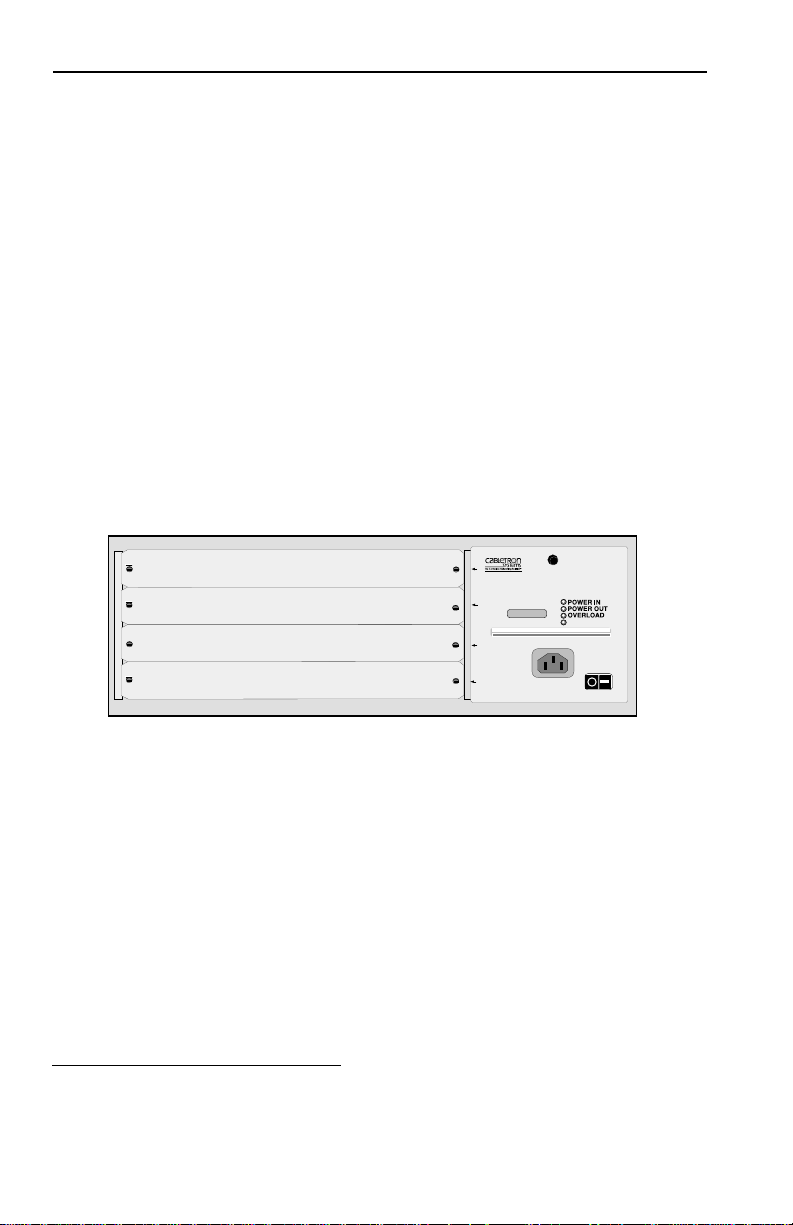
The front panel of the power supply module of the 7C04 Chassis
(Figure 3-1) contains four LANVIEW LEDs to assist you in
troubleshooting the power supply. The color of each LED and the
course of action to pursue are detailed in Table 3-1 through
Table 3-4.
Note:
LANVIEW
LEDs
For information on the LEDs of the individual SmartSwitch
interface modules, refer to each module’s user’s guide.
1
Work Group SmartSwitch
with SECURE
2
3
4
Figure 3-1. Power Supply Module (front panel)
FAST™
SN
100-125V-3.8A
200-250V-1.9A
VIRTUAL NETWORKING
POWER IN
POWER OUT
OVERLOAD
FANS
3-1
Page 21

Troubleshooting
Table 3-1. POWER IN LED
LED Color Indicates Action
Green The power supply’s input
power is acceptable.
Normal Operation.
Red The power supply’s input
power is not sufficient.
Off The power supply has no
input power.
Table 3-2. POWER OUT LED
No action necessary.
Inspect the power
supply’s power outlet,
the power cord, and the
power cord’s connection
to the electrical outlet.
Make sure the power
supply’s power switch is
in the On (-) position.
Make sure the power
supply’s power cord is
securely plugged into the
power supply and
securely plugged into an
electrical outlet. Also
make sure the electrical
outlet is operating
properly.
LED Color Indicates Action
Green The power supply’s
No action necessary.
output (DC) power is
sufficient. Normal
Operation
Red The power supply’s
output power is not
Contact Cabletron
Technical Support.
sufficient.
3-2
Page 22

Troubleshooting
Table 3-3. OVERLOAD LED
LED Color Indicates Action
Green Normal operation No action necessary.
Red The modules within the
chassis are attempting to
Contact Cabletron
Technical Support.
draw an amount of DC
power that exceeds the
power supply’s
maximum DC power
output.
Table 3-4. FAN LED
LED Color Indicates Action
Green Normal operation No action necessary.
Red One (or both) of the
power supply’s fans has
Contact Cabletron
Technical Support.
failed.
3-3
Page 23

CHAPTER 4
TECHNICAL SPECIFICATIONS
This chapter includes the technical specifications for Cabletron
Systems 7C04 Chassis. Cabletron Systems reserves the right to
change these specifications at any time without notice.
4.1 SAFETY
It is the responsibility of the person who sells the chassis to ensure
that the total system meets allowed limits of conducted and
radiated emissions.
The 7C04 Chassis meets the requirements of:
• UL1950
• CSA C22.2 No. 950
• EN60950
• IEC 950
4.2 EMI
The 7C04 Chassis meets the requirements of:
• EN55022 Class A
• FCC Part 15 Class A
• VCCI Class I
4.3 IMMUNITY
The 7C04 Chassis meets the requirements of EN50082-1 including:
• IEC 801-2 ESD
• IEC 803-1 radiated immunity
• IEC 801-4 EFT/B.
4-1
Page 24

Technical Specifications
4.4 SERVICE
MTBF: >200,000 hours
MTTR: <0.5 hour
4.5 POWER
AC Input: 100 - 125 volts, 3.8 amps
200 - 250 volts, 1.9 amps
50/60 Hz
DC Output: 5.1 volts
12 volts
Fusing: The input of the power supply
contains a 250 volt (AC) minimum
fuse to protect against internal
damage. This fuse is not user
servicable.
4.6 PHYSICAL
4.6.1 Dimensions
34.8 D x 16.0 H x 43.2 W centimeters
(13.7 D x 6.3 H x 17.0 W inches)
4.6.2 Weight
Unit: <13.5 kgs. ( <30 lbs.)
Shipping: <13.5 kgs. ( <30 lbs.)
4-2
Page 25

Technical Specifications
4.7 ENVIRONMENTAL
Operating Temperature: +5° to +40° C (+41° to +104° F)
Storage Temperature: -30° to +90° C (-22° to +194° F)
Relative Humidity: 5 to 95% (non-condensing)
4-3
 Loading...