

Page 1
6SSRM-02
RESET
10/100 MGMT
C
O
M
CPU
2
1
Rx
Tx Link
AN
Rx
Tx Link
AN
1000BASE-SX
6SSRLC-SX
2
1
Rx
Tx Link
AN
Rx
Tx Link
AN
1000BASE-SX
6SSRLC-SX
SmartSwitch 6000
Advanced Router Module
Installation/User’s Guide
3
4
9033295-01
Page 2

Page 3

NOTICE
Cabletron Systems reserves the right to make changes in specifications and other information contained in this document
without prior notice. The reader should in all cases consult Cabletron Systems to determine whether any such changes
have been made.
The hardware, firmware, or software described in this manual is subject to change without notice.
IN NO EVENT SHALL CABLETRON SYSTEMS BE LIABLE FOR ANY INCIDENTAL, INDIRECT, SPECIAL, OR
CONSEQUENTIAL DAMAGE S WHATSOEVER (INCLUDING BUT NOT LIMITED T O LOST PR OFITS) ARISING OUT OF OR
RELATED TO THIS MANUAL OR THE INFORMATION CONTAINED IN IT, EVEN IF CABLETRON SYSTEMS HAS BEEN
ADVISED OF, KNOWN, OR SHOULD HAVE KNOWN, THE POSSIBILITY OF SUCH DAMAGES.
Cabletron Systems, Inc.
35 Industrial W a y
Rochester, NH 03866-5005
2000 by Cabletron Systems, Inc.
All Rights Reserved
Printed in the United States of America
Order Number: 9033295-01
Cabletron Systems, and LANVIEW are registered trademarks an d SmartSwitch is a trademark of
Cabletron Systems, Inc.
Spectrum is a tr ademark of Aprisma Managemen t Technologies, Inc.
All other product names mentioned in this manual may be trademarks or registered trademarks of their respective
companies.
FCC NOTICE
This device comp lie s with Part 15 of the FCC rules. Operation is subject to the fo llowing two conditions: (1) this device
may not cause harmful interference, and (2) this device must accept any interference received, including interference that
may cause undesired operation.
NOTE: This equipment has been tested and found to comply with the limits for a Class A digital device, pursuant to
Part 15 of the FCC rules. These limits are desi gned to provide reasonable protection against harmful interference when
the equipment is operated in a commercial environment. This equipment uses, generates, and can radiate radio frequency
energy and if not installed in accordance with the operator’s manual, may cause harmful interference to radio
communications. Operation of this equipment in a residential area is likely to cause interference in which case the user
will be required to correct th e in terference at his own expense.
WARNING: Changes or modifications made to this device which are not expressly approved by the party responsible for
compliance could void the user’s authority to operate the equipment.
i
Page 4

INDUSTRY CANADA NOTICE
This digital apparatus does not exceed the Class A limits for radio noise emissions from digital apparatus set out in the
Radio Interference Regulations of the Canadian Department of Communications.
Le présent appareil numérique n’émet pas de bruits radioélectriques dépassant les limites applicables aux appareils
numériques de la class A prescrites dans le Règlement sur le brouillage radioélectrique édicté par le ministère des
Communications d u C anada.
NOTICE: The Industry Canada label identifies certified equipment. This certification means that the equipment meets
telecommunications network protective, operational and safety requir ements as prescribed in the appropriate Terminal
Equipment Technical Requirements do cuments (s). The d epartment d oes not gua rante e the equipm ent will o perate to the
user’s satisfaction.
Before installing this equipment, users should ensure that it is permissible to be connected to the facilities of the local
telecommunicati ons company. The equipment must also be installed using an acceptable met hod of connection. The
customer should be aware that compliance with the above conditions may not prevent degradation of service in some
situations.
Repairs to certifie d equipment should be coordinated by a re presentative designated by the supplier. Any repairs or
alterations made by the user to this equipment, or equipment malfunctions, may give the telecommunications company
cause to request the user to disconnect the equipment.
Users should ensure for their own protection that the electrical ground connections of the power utility, telephone lines
and internal metallic water pipe system, if present, are connected together. This precaution may be particularly important
in rural areas. Caution: Users should not attempt to make such connections themselves, but should contact the
appropriate electric inspection authority, or electrician, as appropriate.
NOTICE: The Ringer Equivalence Number (REN) assigned to each terminal device provides an indication of the
maximum number of terminals allowed to be connected to a telephone interface. The termination on an interface may
consist of any combination of devices subject only to the requirement that the sum of the ringer equivalence Numbers of
all the devices does not exceed 5.
VCCI NOTICE
This is a Class A product based on the standard of the Voluntary Control Council for Interference by Information
T echnolog y Equipment (VCCI). If this equipment is used in a domestic en vironment, radio disturbance may arise. When
such trouble occurs, the user may be required to take corrective actions.
ii
Page 5

CABLETRON SYSTEMS, INC.
PROGRAM LICENSE AGREEMENT
IMPORTANT:THIS LICENSE APPLIES FOR USE OF PRODUCT IN THE FOLLOWING
GEOGRAPHICAL REGIONS:
CANADA
MEXICO
CENTRAL AMERICA
SOUTH AMERICA
BEFORE OPENING OR UTILIZING THE ENCLOSED PRODUCT, CAREFULLY READ
THIS LICENSE AGREEMENT.
This document is an agreement (“Agreement”) between You, the end user, and Cabletron Systems, Inc. (“Cabletron”)
that sets forth your rights and obligations with respect to the Cabletron software program (“Program”) in the package.
The Program may be contained in firmware, chips or other media. UTILIZING THE ENCLOSED PRODUCT, YOU
ARE AGREEING TO BECOME BOUND BY THE TERMS OF THIS AGREEMENT, WHICH INCLUDES THE
LICENSE AND THE LIMITATION OF WARRANTY AND DISCLAIMER OF LIABILITY. IF YOU DO NOT
AGREE TO THE TERMS OF THIS AGREEMENT, RETURN THE UNOPENED PRODUCT TO CABLETRON OR
YOUR DEALER, IF ANY, WITHIN TEN (10) DAYS FOLLOWING THE DATE OF RECEIPT FOR A FULL
REFUND.
IF YOU HAVE ANY QUESTIONS ABOUT THIS AGREEMENT, CONTACT CABLETRON SYSTEMS
+1- 603-332-9400. Attn: Legal Department.
1. LICENSE. You have the right t o use on l y th e o ne (1) c op y of th e Program provided in this package subject to the
terms and conditions of this License Agreement.
You may not copy, reproduce or transmit any part of the Program except as permitted by the Copyright Act of the
United States or as authorized in wri ting by Cabletron.
2. OTHER RESTRICTIONS. You may not reverse engineer, decompile, or disassemble the Progra m.
3. APPLICABLE LAW. This License Agreement shall be interpreted and governed under the laws and in the state
and federal courts of New Hampshire. You accept the personal jurisdiction and venue of the New Hampshire courts.
4. EXPORT REQUIREMENTS. You understand that Cabletron and its Affiliates are subject to regulation by
agencies of the U. S. Government, in cluding the U.S. De partment of Commerce, which prohibit export or divers ion of
certain technical products to certain co untries, unless a license to e xport the product is obtained from the U.S . Government
or an exception from obtaining such license may be relied upon by the exporting party.
If the Program is exported from the United States pursuant to the License Exception CIV under the U.S. Export
Administration Regulations, Yo u agree that You are a civil end user of the Program and agree that You will use the
Program for civil en d uses only and not for mi litary pu rpo s es.
iii
Page 6

If the Program is exported from the United States pursuant to the License Exception TSR under the U.S. Export
Administration Regulations, in addition to the restriction on transfer set forth in Sections 1 or 2 of this Agreement, You
agree not to (i) reexport or release the Program, the source code for the Program or technology to a national of a country
in Country Groups D:1 or E:2 (Albania, Armenia, Azerbaijan, Belarus, Bulgaria, Cambodia, Cuba, Estonia, Georgia,
Iraq, Kazakhstan, Kyrgyzstan, Laos, Latvia, Libya, Lithuania, Moldova, North Korea, the People’s Republic of China,
Romania, Russia, Rwanda, Tajikistan, Turkmenistan, Ukraine, Uzbekistan, Vietnam, or such other countries as may be
designated by the United States Government), (ii) export to Country Groups D:1 or E:2 (as de fine d herein) the direct
product of the Pro gram or t he tec hn olog y, if such foreign produced direct p rod uc t is su bject to national security cont rols
as identified on the U.S. Commerce Control List, or (iii) if the direct product of the technology is a com pl ete plant o r
any major component of a plant, export to Country Groups D:1 or E:2 the direct product of the plant or a major
component thereof, if such foreign produced direct product is subject to national security controls as identified on the
U.S. Commerce Control List or is subject to State Department controls under the U.S. Munitions List.
5. UNITED STATES GOVERNMENT RESTRICTED RIGHTS. The enclosed Product (i) was develop ed so le ly
at private expense; (ii) conta ins “restricted computer software ” submitted with restricted rights in accordance with section
52.227-19 (a) through (d) of the Commercial Computer Software-Restricted Rights Clause and its successors, and (iii) in
all respects is proprietary data belonging to Cabletron and/or its suppliers. For Department of Defense units, the Product
is considered commercial computer software in accordance with DFARS section 227.7202-3 and its successors, and use,
duplication, or disclosure by the Government is subject to restrictions set forth herein.
6. EXCLUSION OF WARRANTY. Except as may be specifically provided by Cabletron in writing, Cabletr on
makes no warranty , expressed or impl ied, concerning t he Program (inclu ding its documentation and media).
CABLETRON DISCLAIMS ALL WARRANTIES, OTHER THAN THOSE SUPPLIED TO YOU BY
CABLETRON IN WRITING, EITHER EXPRESS OR IMPLIED, INCLUDING BUT NO T LIMITED TO IMPLIED
WARRANTIES OF MERCHANTABILITY AND FITNESS FOR A PARTICULAR PURPOSE, WITH RESPECT TO
THE PROGRAM, THE ACCOMPANYING WRITTEN MATERIALS, AND ANY ACCOMPANYING HARDWARE.
7. NO LIABILITY FOR CONSEQUENTIAL DAMAGES. IN NO EVENT SHALL CABLETRON OR ITS
SUPPLIERS BE LIABLE FOR ANY DAMAGES WHATSOEVER (INCLUDING, WITHOUT LIMITATION,
DAMAGES FOR LOSS OF BUSINESS, PROFITS, BUSINESS INTERRUPTION, LOSS OF BUSINESS
INFORMATION, SPECIAL, INCIDENTAL, CONSEQUENTIAL, OR RELIANCE DAMAGES, OR OTHER LOSS)
ARISING OUT OF THE USE OR INABILITY TO USE THIS CABLETRON PRODUCT, EVEN IF CABLETRON
HAS BEEN ADVISED OF THE POSSIBILITY OF SUCH DAMAGES. BECAUSE SOME STATES DO NOT
ALLOW THE EXCLUSION OR LIMITATION OF LIABILITY FOR CONSEQUENTIAL OR INCIDENTAL
DAMAGES, OR IN THE DURATION OR LIMITATION OF IMPLIED W ARRANTIES IN SOME INSTANCES, THE
ABOVE LIMITATION AND EXCLUSIONS MAY NOT APPLY TO YOU.
iv
Page 7

CABLETRON SYSTEMS SALES AND SERVICE, INC.
PROGRAM LICENSE AGREEMENT
IMPORTANT: THIS LICENSE APPLIES FOR USE OF PRODUCT IN THE UNITED S TATES OF AMERICA
AND BY UNITED STATES OF AMERICA GOVERNMENT END USERS.
BEFORE OPENING OR UTILIZING THE ENCLOSED PRODUCT, CAREFULLY READ
THIS LICENSE AGREEMENT.
This document is an agreement (“Agreement”) between Y ou, the end user, and Cabletron Systems Sales and Service, Inc.
(“Cabletron”) that sets forth your rights and obligations with respect to the Cabletron software program (“Program”) in
the package. The Program may be contained in firmware, chips or other media. UTILIZING THE ENCLOSE D
PRODUCT, YOU ARE AGREEING TO BECOME BOUND BY THE TERMS OF THIS AGREEMENT, WHICH
INCLUDES THE LICENSE AND THE LIMITATION OF WARRANTY AND DISCLAIMER OF LIABILITY. IF
YOU DO NOT AGREE TO THE TERMS OF THIS AGREEMENT, RETURN THE UNOPENED PRODUCT TO
CABLETRON OR YOUR DEALER, IF ANY, WITHIN TEN (10) DAYS FOLLOWING THE DATE OF RECEIPT
FOR A FULL REFUND.
IF YOU HAVE ANY QUESTIONS ABOUT THIS AGREEMENT, CONTACT CABLETRON SYSTEMS
+1-603-332-9400. Attn: Legal Department.
1. LICENSE. You have the right to use only the one (1) copy of the Program provided in this package subject to the
terms and conditions of this License Agreement.
You may not copy, reproduce or transmit any part of the Program except as permitted by the Copyright Act of the
United States or as authorized in wri ting by Cabletron.
2. OTHER RESTRICTIONS. You may not reverse engineer, decompile, or disassemble the Program.
3. APPLICABLE LAW. This License Agreement shall be interpreted and governed under the laws and in the state
and federal courts of New Hampshire. You accept the personal jurisdiction and venue of the New Hampshire courts.
4. EXPORT REQUIREMENTS. You understand that Cabletron and its Affiliates are subject to regulation by
agencies of the U. S. Government, in cluding the U.S. De partment of Commerce, which prohibit export or divers ion of
certain technical products to certain co untries, unless a license to e xport the product is obtained from the U.S . Government
or an exception from obtaining such license may be relied upon by the exporting party.
If the Program is exported from the United States pursuant to the License Exception CIV under the U.S. Export
Administration Regulations, Yo u agree that You are a civil end user of the Program and agree that You will use the
Program for civil en d uses only and not for mi litary pu rpo s es.
If the Program is exported from the United States pursuant to the License Exception TSR under the U.S. Export
Administration Regulations, in addition to the restriction on transfer set forth in Sections 1 or 2 of this Agreement, You
agree not to (i) reexport or release the Program, the source code for the Program or technology to a national of a country
in Country Groups D:1 or E:2 (Albania, Armenia, Azerbaijan, Belarus, Bulgaria, Cambodia, Cuba, Estonia, Georgia,
Iraq, Kazakhstan, Kyrgyzstan, Laos, Latvia, Libya, Lithuania, Moldova, North Korea, the People’s Republic of Ch ina,
Romania, Russia, Rwanda, Tajikistan, Turkmenistan, Ukraine, Uzbekistan, Vietnam, or such other countri es as may be
designated by the Uni ted States Government), (ii) export to Countr y Groups D:1 or E:2 (as d efine d herein) the direct
product of the Pro gra m or th e te chn olo g y, if such foreign produced direct p rod uc t is su bje ct to na tio n al securi ty c o ntro ls
as identified on the U.S. Commerce Control List, or (iii) if the direct product of the technology is a complete plant o r
any major component of a plant, export to Country Groups D:1 or E:2 the direct product of the plant or a major
component thereof , if such foreig n pro duc ed dire ct produc t is subje ct to natio n al security controls as identified on the
U.S. Commerce Control List or is subject to State Department controls under the U.S. Munitions List.
v
Page 8

5. UNITED STATES GOVERNMENT RESTRICTED RIGHTS. The enclosed Product (i) was develop ed so le ly
at private expense; (ii) conta ins “restricted computer software ” submitted with restricted rights in accordance with section
52.227-19 (a) through (d) of the Commercial Computer Software-Restricted Rights Clause and its successors, and (iii) in
all respects is proprietary data belonging to Cabletron and/or its suppliers. For Department of Defense units, the Product
is considered commercial computer software in accordance with DFARS section 227.7202-3 and its successors, and use,
duplication, or disclosure by the Government is subject to restrictions set forth herein.
6. EXCLUSION OF WARRANTY. Except as may be specifically provided by Cabletron in writing, Cabletron
makes no warranty, expressed or implied, concernin g the Program (including its documentation and media).
CABLETRON DISCLAIMS ALL WARRANTIES, OTHER THAN THOSE SUPPLIED TO YOU BY
CABLETRON IN WRITING, EITHER EXPRESS OR IMPLIED, INCLUDING BUT NO T LIMITED TO IMPLIED
WARRANTIES OF MERCHANTABILITY AND FITNESS FOR A PARTICULAR PURPOSE, WITH RESPECT TO
THE PROGRAM, THE ACCOMPANYING WRITTEN MATERIALS, AND ANY ACCOMPANYING HARDWARE.
7. NO LIABILITY FOR CONSEQUENTIAL DAMAGES. IN NO EVENT SHALL CABLETRON OR ITS
SUPPLIERS BE LIABLE FOR ANY DAMAGES WHATSOEVER (INCLUDING, WITHOUT LIMITATION,
DAMAGES FOR LOSS OF BUSINESS, PROFITS, BUSINESS INTERRUPTION, LOSS OF BUSINESS
INFORMATION, SPECIAL, INCIDENTAL, CONSEQUENTIAL, OR RELIANCE DAMAGES, OR OTHER LOSS)
ARISING OUT OF THE USE OR INABILITY TO USE THIS CABLETRON PRODUCT, EVEN IF CABLETRON
HAS BEEN ADVISED OF THE POSSIBILITY OF SUCH DAMAGES. BECAUSE SOME STATES DO NOT
ALLOW THE EXCLUSION OR LIMITATION OF LIABILITY FOR CONSEQUENTIAL OR INCIDENTAL
DAMAGES, OR IN THE DURATION OR LIMITATION OF IMPLIED W ARRANTIES IN SOME INSTANCES, THE
ABOVE LIMITATION AND EXCLUSIONS MAY NOT APPLY TO YOU.
vi
Page 9

CABLETRON SYSTEMS LIMITED
PROGRAM LICENSE AGREEMENT
IMPORTANT: THIS LICENSE APPLIES FOR THE USE OF THE PRODUCT IN THE FOLLOWING
GEOGRAPHICAL REGIONS:
EUROPE
MIDDLE EAST
AFRICA
ASIA
AUSTRALIA
P ACIFIC RIM
BEFORE OPENING OR UTILIZING THE ENCLOSED PRODUCT, CAREFULLY READ
THIS LICENSE AGREEMENT.
This document is an agreement (“Agreement”) between Y ou, the end user, and Cabletron Systems Limited (“Cabletron”)
that sets forth your rights and obligations with respect to the Cabletron software program (“Program”) in the package.
The Program may be contained in firmware, chips or other media. UTILIZING THE ENCLOSED PRODUCT, YOU
ARE AGREEING TO BECOME BOUND BY THE TERMS OF THIS AGREEMENT, WHICH INCLUDES THE
LICENSE AND THE LIMITATION OF WARRANTY AND DISCLAIMER OF LIABILITY. IF YOU DO NOT
AGREE TO THE TERMS OF THIS AGREEMENT, RETURN THE UNOPENED PRODUCT TO CABLETRON OR
YOUR DEALER, IF ANY, WITHIN TEN (10) DAYS FOLLOWING THE DATE OF RECEIPT FOR A FULL
REFUND.
IF YOU HAVE ANY QUESTIONS ABOUT THIS AGREEMENT, CONTACT CABLETRON SYSTEMS
+1-603-332-9400. Attn: Legal Department.
1. LICENSE. You have the right t o use on l y th e o ne (1) c op y of th e Program provided in this package subject to the
terms and conditions of this License Agreement.
You may not copy, reproduce or transmit any part of the Program except as permitted by the Copyright Act of the
United States or as authorized in wri ting by Cabletron.
2. OTHER RESTRICTIONS. You may not reverse engineer, decompile, or disassemble the Progra m.
3. APPLICABLE LAW. This License Agreement shall be governed in accordance with English law. The English
courts shall have exclusive jurisdiction in the event of any disputes.
4. EXPORT REQUIREMENTS. You understand that Cabletron and its Affiliates are subject to regulation by
agencies of the U. S. Government, in cluding the U.S. De partment of Commerce, which prohibit export or divers ion of
certain technical products to certain co untries, unless a license to e xport the product is obtained from the U.S . Government
or an exception from obtaining such license may be relied upon by the exporting party.
If the Program is exported from the United States pursuant to the License Exception CIV under the U.S. Export
Administration Regulations, Yo u agree that You are a civil end user of the Program and agree that You will use the
Program for civil en d uses only and not for mi litary pu rpo s es.
vii
Page 10

If the Program is exported from the United States pursuant t o the License Exception TSR under the U.S. Export
Administration Regulations, in addition to the restriction on transfer set forth in Sections 1 or 2 of this Agreement, You
agree not to (i) reexport or release the Program, the source code for the Program or technology to a national of a country
in Country Groups D:1 or E:2 (Albania, Armenia, Azerbaijan, Belarus, Bulgaria, Cambodia, Cuba, Estonia, Georgia,
Iraq, Kazakhstan, Kyrgyzstan, Laos, Latvia, Libya, Lithuania, Moldova, North Korea, the People’s Republic of China,
Romania, Russia, Rwanda, Tajikistan, Turkmenistan, Ukraine, Uzbekistan, Vietnam, or such other countries as may be
designated by the United States Government), (ii) export to Country Groups D:1 or E:2 (as de fine d herein) the direct
product of the Pro gram or t he tec hn olog y, if such foreign produced direct p rod uc t is su bject to national security cont rols
as identified on the U.S. Commerce Control List, or (iii) if the direct product of the technology is a com pl ete plant o r
any major component of a plant, export to Country Groups D:1 or E:2 the direct product of the plant or a major
component thereof, if such foreign produced direct product is subject to national security controls as identified on the
U.S. Commerce Control List or is subject to State Department controls under the U.S. Munitions List.
5. UNITED STATES GOVERNMENT RESTRICTED RIGHTS. The enclosed Product (i) was develop ed so le ly
at private expense; (ii) conta ins “restricted computer software ” submitted with restricted rights in accordance with section
52.227-19 (a) through (d) of the Commercial Computer Software-Restricted Rights Clause and its successors, and (iii) in
all respects is proprietary data belonging to Cabletron and/or its suppliers. For Department of Defense units, the Product
is considered commercial computer software in accordance with DFARS section 227.7202-3 and its successors, and use,
duplication, or disclosure by the Government is subject to restrictions set forth herein.
6. EXCLUSION OF WARRANTY. Except as may be specifically provided by Cabletron in writing, Cabletron
makes no warranty, expressed or implied, concernin g the Program (including its documentation and media).
CABLETRON DISCLAIMS ALL WARRANTIES, OTHER THAN THOSE SUPPLIED TO YOU BY
CABLETRON IN WRITING, EITHER EXPRESS OR IMPLIED, INCLUDING BUT NO T LIMITED TO IMPLIED
WARRANTIES OF MERCHANTABILITY AND FITNESS FOR A PARTICULAR PURPOSE, WITH RESPECT TO
THE PROGRAM, THE ACCOMPANYING WRITTEN MATERIALS, AND ANY ACCOMPANYING HARDWARE.
7. NO LIABILITY FOR CONSEQUENTIAL DAMAGES. IN NO EVENT SHALL CABLETRON OR ITS
SUPPLIERS BE LIABLE FOR ANY DAMAGES WHATSOEVER (INCLUDING, WITHOUT LIMITATION,
DAMAGES FOR LOSS OF BUSINESS, PROFITS, BUSINESS INTERRUPTION, LOSS OF BUSINESS
INFORMATION, SPECIAL, INCIDENTAL, CONSEQUENTIAL, OR RELIANCE DAMAGES, OR OTHER LOSS)
ARISING OUT OF THE USE OR INABILITY TO USE THIS CABLETRON PRODUCT, EVEN IF CABLETRON
HAS BEEN ADVISED OF THE POSSIBILITY OF SUCH DAMAGES. BECAUSE SOME STATES DO NOT
ALLOW THE EXCLUSION OR LIMITATION OF LIABILITY FOR CONSEQUENTIAL OR INCIDENTAL
DAMAGES, OR IN THE DURATION OR LIMITATION OF IMPLIED W ARRANTIES IN SOME INSTANCES, THE
ABOVE LIMITATION AND EXCLUSIONS MAY NOT APPLY TO YOU.
viii
Page 11

DECLARATION OF CONFORMITY
Application of C ou ncil D ir e ct ive(s): 89/336/EEC
73/23/EEC
Manufacturer’s Name: Cabletron Systems, Inc.
Manufacturer ’s Address: 35 Industrial Way
PO Box 5005
Rochester, NH 03867
European Representative Name: Mr. J. Solari
European Representative Address: Cabletro n Sys tems Limited
Nexus House, Newbury Business Park
London Road, Newbury
Berkshire RG14 2PZ, England
Conformance to D ir ective(s)/Product Standards: EC Directive 89/336/ EEC
EC Directive 73/23/ EEC
EN 55022
EN 50082-1
EN 60950
Equipment Type/Environment: Networking Equipment, for use in a Commercial
or Light Industrial Environment.
We the undersigned, hereby declare, under our sole responsibility, that the equipment packaged with this
notice conforms to the above directives.
Manufacturer Legal Repr esentative in Eu ro pe
Mr. Ronald Fotino Mr. J. Solari
___________________________________ ___________________________________
Full Name Full Name
Compliance Engi neering Manager Managing Director - E.M.E.A.
_______________ ____________________ ___________________________________
Title Title
Rochester, NH, USA Newbury, Berkshire, England
___________________________________ ___________________________________
Location Location
ix
Page 12

x
Page 13

Chapter 1 Introduction
Specifications...............................................................................................................1-1
TCP/UDP Services ....... ...... ....... ...... ....... ...... ....... ...... ...... ................................1-4
Features............................. ....... ...... ....... ...... ....... ...... ....................................... ............1-4
Bridging........................ ....................................... ...................................... ......1-4
Port and Protocol VLANs................................................................................1-5
Routing............................................................................................................1-5
IP Routing........................................................................................1-6
IP Multicast Routing.........................................................................1-6
IPX Routing .....................................................................................1-6
Layer-4 Switching............................................................................................1-7
Security...........................................................................................................1-7
Quality of Service............................................................................................1-8
Statistics..........................................................................................................1-8
Management Platforms...................................................................................1-8
Hardware Overview......................................................................................................1-9
Module ............................................................................................................1-9
External Controls...........................................................................1-11
Motherboard Features...................................................................................1-11
Boot Flash .....................................................................................1-11
RAM Memory.................................................................................1-11
Line Cards.....................................................................................................1-12
10/100BASE-TX Line Card............................................................1-12
100BASE-FX Line Card.................................................................1-14
1000BASE-SX Line Card ..............................................................1-16
1000BASE-LX Line Card...............................................................1-18
1000BASE-LLX (70KM).................................................................1-21
Dual Serial and Quad Serial – C/CE Expansion Modules.............1-22
Getting Help...............................................................................................................1-24
Contents
Chapter 2 Installation
Unpacking the Module .................................................................................................2-2
Installing the Line Cards............................................ ....................................... ...... ......2-2
Installing the Module into the 6C105 Chassis..............................................................2-3
Completing the Installation...........................................................................................2-5
xi
Page 14

Contents
Chapter 3 Software Installation and Setup
Powering On and Booting the Software.......................................................................3-1
Starting the Command Line Interface..........................................................................3-2
Access Modes.................................................................................................3-2
Basic Line Editing Commands ........................................................................3-3
Setting Basic System Information................................................................................3-4
Setting Up SNMP Community Strings..........................................................................3-7
Setting Up Passwords..................................................................................................3-9
Setting the DNS Domain Name and Address ............................................................3-10
Setting SYSLOG Parameters.....................................................................................3-12
Loading System Image Software...............................................................................3-14
Loading Boot PROM Software...................................................................................3-16
Activating Configuration Changes and Saving the Configuration File........................3-17
Activating the Configuration Commands in the Scratchpad..........................3-18
Saving the Active Configuration to the Startup Configuration File................3-18
Viewing the Current Configuration................................................................3-19
Chapter 4 Installing and Starting Cabletron CoreWatch
What Is Cabletron CoreWatch?....................................................................................4-1
System Requirements..................................................................................................4-2
Installing Cabletron CoreWatch....................................................................................4-2
Installing on a Solaris System.........................................................................4-2
Installing on a Windows NT or Windows 95/98 System..................................4-3
Starting CoreWatch......................................................................................................4-4
Starting CoreWatch in Solaris.........................................................................4-4
Starting CoreWatch in Windows NT or Windows 95/98..................................4-5
Starting CoreWatch from within SPECTRUM Enterprise Manager.................4-5
Starting CoreWatch from within HP OpenView 5.x.........................................4-6
Chapter 5 Troubleshooting
xii
Page 15

1
Introduction
The Cabletron Systems SmartSwitch 6000 Advanced Router Module, the 6SSRM-02, provides
non-blocking, high-speed Layer-2 (switching), Layer-3 (routing), and Layer-4 (application)
switching. This cha pter pro vides a basi c over view of the 6SSRM-02 softw are and har dware fea ture
set.
• If you want to install the 6SSRM-02 now, see Chap ter 2, “Installation”.
• If you want to boot the 6SSRM-02 software and perform basic configuration tasks now, see
Chapter 3, “Software Installation and Setup”.
• If you want to set up a management stati on for using Core Watch, see Chapter 4, “Installing and
Starting Cabletron CoreWatch”.
Specifications
The 6SSRM-02 provides high-speed switching and full non-blocking throughput. The hardware
provides high-speed performance regardless of the performance monitoring, filtering, and Quality
of Service (QoS) features enabled by the software. You do not need to accept performance
compromises to run QoS or access control lists (ACLs).
Introduction 1-1
Page 16

Specifications
The following table lists the basic hardware and software specifications for the 6SSRM-02.
Table 1-1 Basic hardware and software specifications
Feature Specification
Throughput • 8.0-Gbps non-blocking switching fabric
• 6.0 million packets-per-second routing throughput
Capacity • Up to 16,000 routes
• Up to 128,000 Layer-4 application flows
• Up to 180,000 Layer-2 MAC addresses
• 4,096 Virtual LANs (VLANs)
• 2,000 Layer-2 security and access-control filters
• 3MB input/output buffering per Gigabit port
• 1MB input/output buffering per 10/100 port
Routing protocols • IP: RIP v1/v2, OSPF, BGP v2/v3/v4
• IPX: RIP, SAP
• Multicast: IGMP, DVMRP
Bridging and
VLAN protocols
Media Interfa ce
• 802.1d Spanning Tree
• 802.1Q (VLAN trunking)
• 802.3 (10Base-T/100Base-TX)
protocols
Quality of Service
(QoS)
• Layer-2 prioritization (802.1p)
• Layer-3 source-destination flows
• Layer-4 source-destination flows
• Layer-4 application flows
RMON • RMON v1/v2 for each port
1-2 Introduction
Page 17

Specifications
Table 1-1 Basic hardware and software specifications (Continued)
Feature Specification
Management • SNMP
• CoreWatch Element Manag er (GUI)
• Emacs-like Command Line Interface (CLI)
Port mirroring • Traffic from specific ports
• Traffic to specific expansion slots (line cards)
This guide and other 6SSRM-02 documentation refers to the 6SSRM-02’s Layer-2, Layer-3, and
Layer-4 sw itchi ng and routi ng. These layer s are based on the I nter nation al Sta ndards Or gani zatio n
(ISO) 7-layer reference model. Here is an example of that model. The 6SSRM-02 operates within
the layers that are not shaded. Notice that Layer-2 is divided into an LLC layer and a MAC layer.
The 6SSRM-02 operates at the MAC layer but not the LLC layer.
Layer 7 Application
Layer 6 Presentation
Layer 5 Session
Layer 4 TCP/UDP - application
Layer 3 IP/IPX - routing
Layer 2 LLC
Layer 2 MAC -bridging
Layer 1 Physical Interfaces
Introduction 1-3
Page 18

Features
TCP/UDP Services
The following table lists some well known TCP/UDP services provided by the 6SSRM-02.
Table 1-2 TCP/UDP services
TCP Port UDP Port Description
23 Telnet
161 SNMP
67 BOOTP/DHCP Relay Agent
520 Routed
Features
This section describes the following 6SSRM-02 features:
• Address-based and flow-based bridging
• Port-based VLANs and protocol-based VLANs
• IP and IPX routing
• Layer-4 (application) switching
• Security
• Quality o f Service (Q oS)
• Statistics
• Management
Bridging
The 6SSRM-02 provides the following types of high-speed bridging:
• Address-based bridging – The 6SSRM-02 performs this type of bridging by looking up the
destination address in an L2 lookup table on the line card that receives the bridge packet from
the network . The L2 loo kup tab le indic ates the e xit po rt(s ) f or t he bri dged pa ck et. I f the pack et
is addressed to the 6SSRM-02’s own MAC address, the packet is routed rather than bridged.
1-4 Introduction
Page 19

Features
• Flow-based bri dging – The 6SSRM-02 performs t hi s t ype of bridging by looking up an entry
in the L2 loo kup table contai ning both the s ource and destina tion addresses o f the bridge pac ket.
Your choice of bridging method does not affect 6SSRM-02 performance. However, address-based
bridging is more efficient because it requires fewer table entries while flow-based bridging
provides tighter management and control over bridged traffic.
The 6SSRM-02 ports perform addres s-base d bridging by def ault , but can be conf ig ured to perfor m
flow-based bridging instead of address-based bridging on a per-port basis. A port cannot be
configured to perform both types of bridging at the same time.
Port and Protocol VLANs
The 6SSRM-02 supports the following types of Virtual LANs (VLANs):
• Port-based VLANs – A port-b ased VLAN is a set of ports that comprise s a Layer -2 broa dcast
domain. The 6SSRM-02 confines MAC-layer broadcasts to the ports in the VLAN on which
the broadcast originates. 6SSRM-02 ports outside the VLAN do not receive the broadcast.
• Protocol-based VLANs – A protocol-based VLAN is a named set of ports that comprises an
IP or IPX broadcast domain. The 6SS RM-02 confines IP or IPX broadcasts to the ports with in
the IP or IPX based VLAN. Protocol-based VLANs sometimes are called subnet VLANs or
Layer-3 VLANs.
You can include the same port in more than one VLAN, even in both port-based and
protocol-based VLANs. Moreover, you can define VLANs that span across multiple
6SSRM-02s. To simplify VLAN administration, the 6SSRM-02 supports 802.1q trunk ports,
which allow yo u to use a si ngle port t o “trunk” t raf f ic from mult iple VLANs to an other 6SSRM-02
or switch which supports 802.1q.
Routing
The 6SSRM-02 provides high-speed routing for the following protocols:
• Internet P rot ocol (IP) – the protocol switching and routing devices use for moving traffic
within the Internet and within many corporate intranets.
• Internet Pac ket Exchange (IPX) – a protocol by Novell used in Netware products.
Note: All other protocols that require routing must be tunneled using IP.
By default, the 6SSRM-02 uses one MAC address for all interfaces. The 6SSRM-02 can be
configured to have a separate MAC address for each IP interface and a separate MAC address for
Introduction 1-5
Page 20

Features
each IPX interf ace . Whe n the 6SSRM -02 re cei ves a packet whose dest in ation MAC address is one
of the 6SSRM-02’s IP or IPX interface MAC addresses, the port that received the packet from the
network uses information in the module’s L3 lookup tables (or information supplied by the
motherboard) to route the packet to its IP destination(s).
You can create only one IP and IPX inte rf ace on a s ingle port or VLAN. You can add second ary IP
addresses to the same IP interface. When you add an interface to a set of ports, you are adding a
VLAN to those ports. Ports that contain IP and IPX interfaces can still perform Layer-2 bridging.
IP Routing
The 6SSRM-02 supports the following IP unicast routing protocols:
• RIP v1 and RIP v2
• OSPF v2
• BGP v2/v3/v4
IP interf aces do not use a sp ecif i c rout in g proto col b y def ault. Whe n you configure an interf ac e for
routing, you also specify the routing protocol the interface will use.
IP Multicast Routing
The 6SSRM-02 supports the following IP multicast routing protocols:
• IGMP v1 and IGMP v2
• DVMRP v3
The 6SSRM-02 does not use a specific IP Multicast routing protocol by default. Configuring an
interface for IP Multicast simultaneously spec ifies its routing protocol.
IPX Routing
The 6SSRM-02 supports the following IPX routing protocols:
• IPX RIP – a version of the Routing Information Protocol (RIP) tailored for IPX
• IPX SAP – the Service Adv ertisement Protoc ol, which allo ws hosts attached to an IPX network
to reach printers, file servers, and other services
By default, IPX routing is enabled on the 6SSRM-02 when an IPX interface is created.
1-6 Introduction
Page 21

Features
Layer -4 Switching
In addition to Layer-2 bridging and Layer-3 routing, the 6SSRM-02 performs Layer-4 switching.
Layer-4 switching is based on applications and flows.
• Layer-4 applications – The 6SSRM-02 understands the application for which an IP or IPX
packet cont ai ns data and therefore enab les you to manage and control tr affic on an application
basis. For IP traf fic, the 6SSRM- 02 looks at the pac ket’ s TCP or UDP por t number to dete rmine
the application. For IPX packets, the 6SSRM-02 looks at the destination socket to determine
the application.
• Layer-4 flows – The 6SSRM-02 can store Layer-4 flows in each line card. A Layer-4 flow
consists of the source and d estination addresses i n the IP or IPX packet combi ned with the TCP
or UDP source and destination port number (for IP) or the source and destination socket (for
IPX). You can therefore manage and control individual flows between hosts on an individual
application basis.
A single host can have many individual Layer-4 entries in the 6SSRM-02. For example, an IP host
might have separate Layer-4 application entries for email, FTP, HTTP, and so on, or separate
Layer-4 flow entries for specific email destinations and for specific FTP and Web connections.
Security
The bridging, routing, and application (Layer-2, Layer-3, and Layer-4) support described in
previous sections enables you to implement security filters that meet the specific needs of your
organization. You can implement the following types of filters to secure traffic on the 6SSRM-02:
• Layer-2 source filters (block bridge traffic based on source MAC address)
• Layer-2 destination filters (block bridge traffic based on destination MAC address)
• Layer-2 flow filters (block bridge traffic based on specific source-destination pairs)
• Layer-3 source filters (block IP or IPX traffic based on source IP or IPX address)
• Layer-3 destination filters (block IP or IPX traffic based on destination IP or IPX address)
• Layer-3 flow filters (block IP or IPX traffic based on specific source-destination pairs)
• Layer-4 appl ication f il ters (bloc k traf f ic base d on UDP or TCP sourc e and desti nation por ts for
IP or source and destination sockets for IPX)
Introduction 1-7
Page 22

Features
Quality of Service
Although the 6SSRM-02 supplies non-blocking high-speed throughput, you can configure the
6SSRM-02 to apply Quality of Service (QoS) policies during peak periods to guaran tee serv ice to
specific hosts, applications, and flows (source-destination pairs). This is especially useful in
networks where the traffic level can exceed the network medium’s capacity.
The 6SSRM-02 QoS is based on four queues: control, high, medium, and low. Control traffic has
the highest priority, high the second highest, and so on. The default priority for all traffic is low.
You can configure QoS policies for the following types of traffic:
• Layer-2 prior it iz ati on (802.1p)
• Layer-3 and Layer-4 application flows
Statistics
The 6SSRM-02 can provide extensive statistical data on demand. You can access the following
types of statistics:
• Layer-2 RMON and MIB II Stat istics – Port statistics f or normal pack ets and for errors (pack ets
in, packets out, CRC errors, and so on)
• Layer-3 RMON v2 Statistics – Statistics for ICMP, IP, IP-interface, IP routing, IP multicast,
VLAN
• Layer-4 RMON v2 Statistics – Statistics for TCP and UDP
Management Platforms
You can manage the 6SSRM-02 using the following management platforms:
• Command Line Interface (CLI) – An EM ACs editor-like interface that accepts typed
commands and responds when applicable with messages or tables. You will use the CLI to
perform the basic setup procedures described in Chapter 3 of this guide.
• CoreWatch – Cabletron Systems’ Java-based device management software. CoreWatch
provides a graphical interface to the 6SSRM-02, providing most of the same monitoring and
control features as the CLI.
• SNMP MIBs and traps – The 6SSRM-02 supports SNMP v1 and many standard networking
MIBs. You can access the 6SSRM-02’s SNMP agent using Cabletron Systems integration
software fo r HP OpenV ie w 5.x on W indo ws NT or Solaris 2.x, or Cabletron Syste ms Spectrum
1-8 Introduction
Page 23

Hardware Overview
on Solaris 2. x. Chapter 3, “Software Instal lation and Setup” in this guide e xplains ho w to set up
SNMP on the 6SSRM-02. Chapter 4, “Installing and Starting Cabletron CoreWatch” explains
how to access the 6SSRM-02’s SNMP agents.
Hardware Overview
This section describes the 6SSRM-02’s hardware specifications. Chapter 2, “Installation” in this
guide de scribes how to in stall the hardware. T his section describes the followi ng hardware:
• Module and external controls
• Motherboard features
• Line Cards
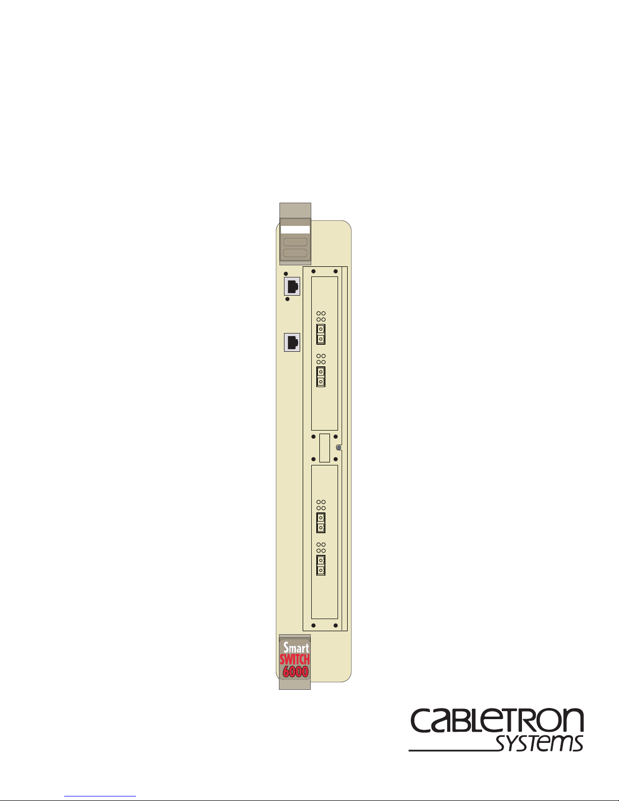
Module
The 6SSRM-02 module contains two expansion slots (slots 1 and 2).
Figure 1-1 shows the front view of a loaded 6SSRM- 02.
Introduction 1-9
Page 24

Hardware Over view
6SSRM-02
RESET
10/100 MGMT
C
O
M
CPU
2
1
Rx
Tx Link
AN
Rx
Tx Link
AN
1000BASE-SX
6SSRLC-SX
2
1
Rx
Tx Link
AN
Rx
Tx Link
AN
1000BASE-SX
6SSRLC-SX
3
4
1-10 Introduction
Figure 1-1 Front View of 6SSRM-02
Page 25

Hardware Overview
External Controls
The 6SSRM-02 has the following external controls. Where appropriate, this guide describes how
to use the controls.
• A COM port for serial connection from a management terminal. Use this port to establish a
direct CLI connection to the 6SSRM-02. The default baud rate is 9600.
• A 10Base-T/100Base-TX Data Terminal Equipment (DTE) port for network connection from
a management terminal. The port is configured as Media Data Interface (MDI). Use this port to
establish a CoreWatch management connection to the 6SSRM-02 over a local or bridged
Ethernet segment.
• A Reset switch. Use this switch to reboot the 6SSRM-02’s motherboard from the internal boot
flash in the event of a system failure. The Re set s witch is recessed in the 6SSRM-02’s ch assis,
so you will have to use a tool like a small allen wrench to activate the switch.
• CPU Status LED: Red Fatal System Error
Yellow Diagnostic Mode
Yellow/Flashing Boot PR OM is Active
Green Functio ning Normally
Motherboard Features
The internal “motherboard” performs all the 6SSRM-02’s computing and routing functions. It
contains syste m-w id e bridging and routing tables. Traffic that does not yet ha ve an entry in the L2
and L3/L4 lookup tables on individual line cards is handled by the motherboard. After processing
traffic, the motherbo ard updates the L2 and L3/L4 tables on the ports that received the traffic. The
ports thus “learn” about how to forward traffic.
Boot Flash
The motherboard has a boot flash containing the 6SSRM-02’s boot software and configuration
files. The system software image file resides on an internal flash chip and can be upgraded from a
TFTP server.
RAM Memory
The 6SSRM-02’s motherboard uses 128MB of RAM to hold routing and other tables. This RAM
is “fixed” and is not removable or upgradable.
Introduction 1-11
Page 26

Hardware Over view
Line Cards
The following Line Cards can be installed in the 6SSRM-02:
• 6SSRLC-TX 8-por t 10/ 100BASE-TX
• 6SSRLC-FX 8-port 100BASE-FX
• 6SSRLC-SX 2-port 1000BASE-SX
• 6SSRLC-LX 2-por t 1000BASE-LX
• 6SSRLC-LX70 1-port 1000BASE-LLX (70 KM)
• 6SSRLC-SER 2-port serial
• 6SSRLC-SERC 4-port serial with compression
• 6SSRLC-SERCE 4-port serial with compression and encryption
Note: Due to a power restriction with the SmartSwitch 6000, the 6SSRM-02 can only support one
linecard when either 6SSRLC-FX or 6SSRLC-TX is installed. Any other combination of two
linecards is fully supported in the SmartSwitch 6000.
10/100BASE-TX Line Card
The 10/100BASE-TX line card contains eight independent Ethernet ports. Each port senses
whether it is connected to a 10-Mbps segment or a 100-Mbps segment and automatically
configures itself as a 10Base-T or 100Base-TX port. Figure 1-2 shows the front panel of the
10/100BASE-TX line card.
Link LED Activity LED
10/100BASE-TX6SSRLC-TX
87654321
10Base-T/100Base-TX ports
Figure 1-2 Front Panel of 10/100BASE-TX Line Card
1-12 Introduction
Page 27

Hardware Overview
Cabling and Connector Specifications
The following table lists the media specifications for the 10/100BASE-TX line card.
Table 1-3 10/100BASE-TX Line Card specifications
Port Type Specification
10Base-T • 802.3 standard
• RJ-45 connector wired as Media Data Interface Crossed
(MDIX); see “10/100BASE-TX Line Card” on page 12
for pin assignments
• EIA Category 3, 4, or 5 unshielded twisted pair cabling
• Maximum 328 feet (100 meters) segment length
100Base-TX • 802.3u standard
• RJ-45 connector wired as Media Data Interface Crossed
(MDIX); see “10/100BASE-TX Line Card” on page 12
for pin assignments
• EIA Category 5 unshielded twisted pair cabling
• Maximum 328 feet (100 meters) segment length
Introduction 1-13
Page 28

Hardware Over view
LEDs
The 10/100BASE-TX line card uses the following LEDs.
Table 1-4 10/100BASE-TX Line Card LEDs
LED Description
Link Each port has two LEDs on its connector. The green LED on
the left side of the connector indicates the link status. When
this LED is lit, the port hardware is detecting that a cable is
plugged into the port and the port has established
communication with the device at the other end.
Activity The amber LED on the right side of each port connector
flashes each time the port’s transceiver sends or receives
packets.
100BASE-FX Line Card
The 100BASE-FX line card provides the same features as the 10/100BASE-TX line card but uses
multimode fiber-optic cable (MMF) to connect to the network.
Figure 1-3 shows the front panel of the 100BASE-FX line card.
6SSRLC-FX
1
Lnk Act Lnk Act Lnk Act Lnk Act Lnk Act Lnk Act Lnk Act Lnk Act
2345678
100BASE-FX port
Figure 1-3 Front panel of 100B ASE-FX Line Card
100BASE-FX
1-14 Introduction
Page 29

Hardware Overview
Cabling and Connector Specifications
The following table lists the media specifications for the 100BASE-FX line card.
Table 1-5 100BASE-FX Line Card specifications
Port type Specification
100Base-FX • 802.3u standard
• SC-style Media Interfa ce Connector (MIC); eit her
connection pin in the MIC can be used for transmit or
receive.
• 62.5 micron multimode fiber-optic cable
• Maximum 412 meters (1352 feet) segment length for
half-duplex links
• Maximum 2 kilometers (6562 feet) segment length for
full-duplex links
LEDs
The 100BASE-FX line card uses the following LEDs.
Table 1-6 100BASE-FX Line Card LEDs
LED Description
Lnk Each port has two LEDs located to the left of the
connector. The green Lnk LED indicates the link status.
When this LED is lit, the port hardware is detecting that
a cable is plugged into the port and the port has
established communication with the device at the other
end.
Act The amber Act LED flashes each time the port’s
transceiver sends or receives packets.
Introduction 1-15
Page 30

Hardware Over view
1000BASE-SX Line Card
The 1000BASE-SX line card contains two independent Gigabit (1000-Mbps) Ethernet ports. The
ports connect to multimode-mode fiber (MMF) cables. Figure 1-4 shows the front panel of the
1000BASE-SX line card.
1000BASE-SX6SSRLC-SX
Tx Link
Tx Link
21
AN
Rx
Gigabit port Gigabit port
AN
Rx
Figure 1-4 Front panel of 1000BASE-SX Line Card
Cabling and Connector Specifications
The following table lists the media specifications for the 1000BASE-SX line card.
Table 1-7 1000BASE-SX Line Card specifications
Port type Specification
1000Base-SX • 802.3z standard (also uses 802.3x for flow control)
• SC-style Media Interface Connector (MIC)
• 62.5 micron or 50 micron multimode fiber-optic cable
• Maximum 275 meters (902 feet) se gment lengt h for 62.5
micron fiber-optic cable, based on installed fiber
bandwidth
1-16 Introduction
• Maximum 550 meters (1804 feet) se gment len gth for 50
micron fiber-optic cable, based on installed fiber
bandwidth
Page 31

LEDs
The 1000BASE-SX line card uses the following LEDs.
Table 1-8 1000BASE-SX Line Card LEDs
LED Description
Per-port Link • Green – indicates that the port hardware detects a cable
plugged into the port and a good link is established.
• Red (intermit tent) – indicate s that the port r eceive d an error
during operation.
• Red (solid) – indicates that the port hardware detects a
cable plugged into the port, however, a bad link is
established.
Hardware Overview
• Off – indicates that no link from exists with the port.
Introduction 1-17
Page 32

Hardware Over view
Per-port Rx • Green – indicates when the port’s transceiver receives
Per-port Tx • Green – indicates when the port’s transceiver transmits
Per-port AN • Green – indicates that the line card is autonegotiating the
Table 1-8 1000BASE-SX Line Card LEDs (Continued)
LED Description
packets.
• Orange – indicates when the port’s transceiver receives
flow-control packets.
packets.
• Orange – indicates when the port’s transceiver transmits
flow-control packets.
operating mode of the link between full-duplex and
half-duplex.
• Orange (inter mit tent) – indicates that aut onegotiation is in
process.
• Orange (solid) – indicates a problem with autonegotiation
configuration.
• Red – indicates an autonegotiation failure. This fault may
occur if the link partner does not support full duplex.
• Off – indicates that autonegotiation has been disabled or
the link is down.
1000BASE-LX Line Card
The 1000BASE-LX line card provides the same features as the 1000BASE-SX line card, and
supports both single-mode fiber (SMF) and MMF. Figure 1-5 shows the front panel of the
1000BASE-LX line card.
1-18 Introduction
Page 33

Tx Link
Tx Link
Hardware Overview
1000BASE-LX6SSRLC-LX
21
AN
Rx
Gigabit port Gigabit port
AN
Rx
Figure 1-5 Front panel of 1000BASE-LX Line Card
Cabling and Connector Specifications
The following table lists the media specifications for the 1000BASE-LX line card.
Table 1-9 1000BASE-LX Line Card specifications
Port type Specification
1000Base-LX • 802.3z standard (also uses 802.3x for flow control)
• SC-style Media Interface Connector (MIC)
• 62.5 micron or 50 micron multimode fiber-optic cable
• 9.5 micron single-mode fiber-optic cable
1. Patch cord required.
1
• Maximum 550 meters (1804 feet)
segment length for
62.5 micron fiber-optic cable, based on installed fiber
bandwidth
• Maximum 550 meters (1804 feet ) segment length for 50
micron fiber-optic cable, based on installed fiber
bandwidth
• Maximum 5 kilometers (16400 feet) segment length for
10 micron single-mode fiber-optic cable
Introduction 1-19
Page 34

Hardware Over view
LEDs
The 1000BASE-LX line card uses the following LEDs.
Table 1-10 1000BASE-LX Line Card LEDs
LED Description
Per-port Link • Green – indicates that the port hardware detects a cable
plugged into the port and a good link is established.
• Red (intermittent) – indicates that the port received an error
during operation.
• Red (solid) – indicates that the port hardware detects a
cable plugged into the port, however, a bad link is
established.
• Off – indicates that no link exists with the port.
1-20 Introduction
Page 35

Hardware Overview
Table 1-10 1000BASE-LX Line Card LEDs (Continued)
LED Description
Per-port Rx • Green – indicates when the port’s transceiver receives
packets.
• Orange – indicates when the port’s transceiver receives
flow-control packets.
Per-port Tx • Green – indicates when the port’s transceiver transmits
packets.
• Orange – indicates when the port’s transceiver transmits
flow-control packets.
Per-port AN • Green – indicates that the line card is autonegotiating the
operating mode of the link between full-duplex and
half-duplex.
• Orange (inter mitt ent) – indicates that aut onegotiation is in
process.
• Orange (solid) – indicates a problem with autonegotiation
configuration.
• Red – indicates an autonegotiation failure. This fault may
occur if the link partner does not support full duplex.
• Off – indicates that autonegotiation has been disabled or
the link is down.
1000BASE-LLX (70KM)
The 1000BASE-LLX line card supports a single port and contains 16 MB of memory. Advanced
optical dri vers have been adde d to t he existing SSR Gigabit line car ds to i ncr eas e di st anc e sup por t
to between 15 and 70 Km over 10 um Single Mode Fiber. Use the 1000 BASE-LX module for
distances less than 5 Km. Figure 1-6 shows the front panel of the 1000BASE-LLX line card.
Introduction 1-21
Page 36

Hardware Over view
1000BASE-LX6SSRLC-LX70
Offline
Online
Tx Link
AN
Rx
1
Gigabit port
Figure 1-6 Front Panel of the 1000BASE-LLX Line Card
Hot
Swap
1-22 Introduction
Page 37

Hardware Overview
Dual Serial and Quad Serial – C/CE Expansion Modules
The Dual Serial line card contains a single dual serial WAN port (two serial ports located on one
high density connector). The Quad Serial – C and Quad Serial – CE line cards each contain two
dual serial WAN ports. In addition, the Quad Serial – C line card includes compression, and the
Quad Serial – CE line card includes compression and encryption, for each WAN port. Figure 1-7
shows the front panel of the Dual Serial WAN line card.
Dual Serial6SSRLC-SER
12
Link
Rx
Tx
1,2
Figure 1-7 Front panel of Dual Serial WAN Line Card
Figure 1-8 shows the front panel of the Quad Serial WAN line card.
12
Link
Rx
Tx
1,2
Figure 1-8 Front panel of Quad Serial – C/CE WAN Line Card
34
Link
Rx
Tx
Quad Serial - C6SSRLC-SERC
3,4
Introduction 1-23
Page 38

Hardware Over view
Cabling and Connector Specifications
The following table lists the media specifications for the Dual Serial and Quad
Serial – C/CE line cards.
Table 1-11 Dual Serial and Quad Serial – C/CE WAN Line Card specifications
Port Type Specification
Dual seri al • V.35, X.21, EIA530, EIA530A, or RS449
• LFH-60 high density connector; see “Dual Serial and
Quad Serial – C/CE Expansion Mo dules” on pag e 23 for
pin assignments
• Recommended 3 meters (10 feet) segment length for
standard WAN Line Card-to-CSU/DSU data port.
1
1. Connector cables for WAN line cards may be ordered from Cabletron Systems. For
detailed information, including part numbers, see “Dual Serial and Quad Serial – C/CE
Expansion Modules” on page 23.
LEDs
The Dual Serial and Quad Serial – C/CE line cards use the following LEDs.
Table 1-12 Dual Serial and Quad Serial – C/CE WAN Line Card LEDs
LED Description
Per-por t Link Indicates th at the li ne card det ects a cabl e plugged i nto the port
and a good link is established.
Per-port Rx Indicates when the port’s transceiver receives data.
Per-port Tx Indicates when the port’s transceiver transmits data.
1-24 Introduction
Page 39

Getting Help
Getting Help
For additional support related to this device or document, contact Cabletron Systems using one of
the following met hods:
World Wide Web http://www.cabletron.com/
Phone (603) 332-9400
Internet mail support@cabletron.com
FTP ftp://ftp.cabletron.com/
Login
Password
To send comments or suggestions concerning this document, contact the
Cabletron Systems Technica l Writing Department via the following
email address: TechWriting@cabletron.com
Make sure to include the document Part Number in the email message.
anonymous
your email address
Before c alling Cabletron Sy stems, have the following information ready:
• Your Cabletron Systems service contract number
• A description of the failure
• A description of any action(s) already taken to resolve the problem (e.g., changing mode
switches, rebooting the unit, etc.)
• The serial and revision numbers of all involved Cabletron Systems products in the network
• A description of your network environment (layout, cable type, etc.)
• Network load and frame size at the time of trouble (if known)
• The device history (i.e., have you returned the device before, is this a recurring problem, etc.)
• Any previous Return Material Authorization (RMA) numbers
Introduction 1-25
Page 40

Getting Help
1-26 Introduction
Page 41

2
Installation
This chapt er provides the instructi ons to install the 6SSRM- 02. A Phillips screwdriver is requir ed
to install options into the module. Follow the order of the sections listed below to correctly install
the module.
• Unpacking the Module
• Installing Options
• Installing the Module into the 6C105 Chassis
• Connecting to the Network
• Completing the Installation
Warning: Only qualified personnel should install the 6SSRM-02.
Note: Read the Release Notes shipped with the module to check for any exceptions to the
supported features and operation documented in this guide.
Installation 2-1
Page 42

Unpacking the Module
Unpacking the Module
Unpack the module as follows:
1. Open the box and remove the packing material protecting the 6SSRM-02.
2. Verify the contents of the carton as listed in Table 2-1.
Table 2-1 Contents of 6SSRM-02 Carton
Item Quantity
6SSRM-02 1
Antistatic Wrist Strap 1
Manual Accessory Kit 1
3. Remove the tape seal on the non-conductive bag to remove the 6SSRM-02.
4. Perform a visual inspection of the module for any signs of physical damage . Contact Cabletron
Systems if there are any signs of damage.
Installing the Line Cards
Two Line Cards can be installed in the 6SSRM-02 module. They must be installed before the
6SSRM-02 module is installed into the 6C105 chassis. The Line Cards are shipped with
installation instruc tions. Refer to these instructions before installing.
Note: Due to a power restriction with the SS6000, the 6SSRM-02 can only support one linecard
when either 6SSRLC-FX or 6SSRLC-TX is installed. Any other combination of two linecards is fully
supported in the SS6000.
2-2 Installation
Page 43

Installing the Module into the 6C105 Chassis
Installing the Module into the 6C105 Chassis
Caution: Failure to observe static safety precautions could cause damage to the 6SSRM-02.
Follow static safety handling rules and wear the antistatic wrist strap provided with the 6C105
chassis.
Do not cut the non-conductive bag to remove the module. Sharp objects contacting the board or
components can cause damage.
The 6SSRM-02 can be installed in any of the slots that are available. To install a module, refer to
Figure 2-1 and proceed as follows:
1. Remove the blank panel co vering the slot in which the modu le wil l be insta lled. All o ther slots
must remain covered to ensure proper airflow and cooling. (Save the blank plate in the event
you need to remove the module.)
2. Carefully remove the module from the shipping box. (Save the box and packing materials in
the event the module must be reshipped.)
3. Locate the antistatic wrist strap shi pped with the 6SSRM-02. Attach the antistati c wrist str ap to
your wrist and plug the cabl e from the an tist atic wrist strap i nto the ESD grou nding rec eptacle
at the upper right corner of the 6C105.
4. Remove the module from the plastic bag. (Save the bag in the event the module must be
reshipped.) Observe all precautions to prevent damage from Electrostatic Discharge (ESD).
Installation 2-3
Page 44

Installing the Module into the 6C105 Chassis
1 2
3
45
PS1
PS2
Plastic
Locking Tab
Slot Number
Circuit Card
Card Guides
Metal Back-Panel
Plastic Locking Tab
Backplane
Connector
6SSRM-02
RESET
10/100 MGMT
C
O
M
CPU
Rx
Tx Link
AN
Rx
Tx Link
AN
21
1000BASE-SX6SSRLC-SX
3
4
6SSRLC-TX
Rx
Tx Link
AN
Rx
Tx Link
AN
21
1000BASE-SX
Figure 2-1 Installing an Interface Module
2-4 Installation
Page 45

Completing the Installation
5. Examine the module for damage. If any damage exists, DO NOT install the module.
Immediately contact Cabletron Systems.
Caution: To prevent damaging the backplane connectors in the following step, take care that the
module slides in straight and properly engages the backplane connectors.
Ensure that the top plastic locking tab lines up with the desired slot number located on the front
panel of the chassis. Refer to Figure 2-1.
6. Locate the slot guides that line up with the number of the slot in which the module will be
installed. Ins tall the module in the chassis by al igning the module circuit card be tween the upper
and lower metal rail guide s of the desir ed slo t, sli ding it into t he cha ssis, a nd locki ng down t he
top and bottom plas tic locking tabs , as shown in Fi gure 2-1. Take care that the module slides in
straight and properly engages the backplane connectors.
7. If the chassis in which the module is installed was powered down for the installation, turn it
back on. Check to see that the CPU LED settles at solid green after a few minutes. If the LED
does not turn solid green, see Chapter 5 for details.
Completing the Installation
After installing the 6SSRM-02 proceed as follows:
1. If the chassis is installed in a rack that has strain-relief brackets, secure the cables by running
the cables along the strain-relief bracket and tying them to the bracket using cable ties.
2. The 6SSRM-02 is now ready to be configured through the CLI interface. Refer to the Command
Line Interface Guide and the User Reference Guide for configuration information.
Installation 2-5
Page 46

Completing the Installation
2-6 Installation
Page 47

Software Installation and Setup
This chapter provides the following software installation and basic setup procedures:
• Powering on and booting the software
• Starting the Command Line Interface (CLI)
• Setting b asic system information
• Setting up SNMP community strings
• Setting up passwords
• Setting the DNS domain name and address
• Setting SYSLOG parameters
3
• Loading system image software
• Loading the boot PROM software
• Activating configuration changes and saving the configuration file
Powering On and Booting the Software
To power on the 6SSRM-02 and boot the software:
1. Make sure any exposed expansi on slots are free of foreign ob jects, such as t ools or your h ands,
and are covered with coverplates.
2. Insert the 6SSRM-02’s into the 6C105 chassis. Assuming that your power source is currently
active, the 6SSRM-02 will automatically power on and attempt to boot using the software
image in the motherboa rd’s boot flash. When the softwa re finishes booting, th e CPU LED lights
up, indicating that the 6SSRM-02 software is online.
Software Installation and Setup 3-1
Page 48

Starting the Command Line Interface
As the software boots, the management console attached to the 6SSRM-02’s COM port displays
messages related to the phases of the boot sequence. When the software is fully booted, the
following message appears on the management console:
Press RETURN to activate console...
3. Press Return (or Enter) to activate the CLI on the console.
Starting the Command Line Interface
To start the Command Line Interface (CLI), power on the system. Startup messages appear on the
console (the terminal attached to the COM port).
After the software is fully booted and you press Return (or Enter) to activate the CLI, the CLI
prompts you for a passw ord. You can defi ne separate pa sswords for login ac cess and Enabl e mode.
The factory default password for both of these is set to blank. (Simply press Return.)
Access Modes
The CLI has the following access modes:
• User – Allows y ou to display b asic informati on and use basic utilities su ch as ping b ut does not
allow you to display SNMP, filter and access control list information, or make other
configurat ion changes. You can tell you are in User mode when the command prompt ends with
>” character.
a “
• Enable – Allo ws you to display SNMP, filt er, and access control info rmat io n as well as all the
information you ca n di splay in User mode. To enter Enable mode, enter the enable command,
then supply the passwo rd when prompted. When you are in Enable mode, the command prompt
ends with a “
• Configure – Allows you to make configuration changes. To enter Configure mode, first enter
Enable mode (enable command), then en ter the conf igure command from the Enabl e command
prompt. When you are in Configure mode, the command prompt ends with “
• Boot – This mode appe ars when the 6SSRM-02 or the system i mage is not found d uring bootup.
You should enter the reboot command to reset the router. If the 6SSRM-02 still fails to bootup,
please call Cabletron Systems. See Gett ing He lp , on page 1-25.
#” character.
(config)#.”
3-2 Software Installation and Setup
Page 49

Starting the Command Line Interface
Note: The command prompt will show the name of the 6SSRM-02 in front of the mode
character(s). The default name is “ssr”. The procedure in “Setting Basic Syst em
Information” on page 3-4 describes how to change the system name.
When you are in Configure or Enable mode, use the exit command or press Ctrl+Z to exit to the
previous access mode.
Note: When you exit Configure mode, the CLI will ask you whether you want to activate the
configuration commands you have issued. If you enter yes or y, the configuration
commands you issued are placed into effect and the 6SSRM-02’s configuration is
changed accordingly . Howe ver , the changes are not written to the Startup configuration file
in the 6SSRM-02’s boot flash and therefore are not reinstated after a reboot. See
“Activating Configuration Changes and Saving the Configuration File” on page 3-17 for
information about saving configuration changes.
Basic Line Editing Commands
The CLI supports EMACs-like line editing commands. The following table lists some commonly
used commands. For a complete set of commands, see the SmartSwitch Router User Reference
Manual.
Table 3-1 Some commonly used CLI commands
Key sequence Command
Ctrl+A Move cursor to beginning of line
Ctrl+B Move cursor back one character
Ctrl+D Delete characte r
Ctrl+E Move cursor to end of line
Ctrl+F Move cursor forward one character
Ctrl+N Scroll to next command in command history ( use the cli show
history command to display the history)
Ctrl+P Scroll to previous command in command history
Ctrl+U Erase entire line
Ctrl+X Erase from cursor to end of line
Ctrl+Z Exit current access mode to previous access mode
Software Installation and Setup 3-3
Page 50

Setting Basic System Information
Setting Basic System Information
Use the procedure in th is section t o set the followin g system information:
• System time and date
• System name
• System location
• Contact name (the person to contact regarding this 6SSRM-02)
Note: Some of the commands in this procedure accept a string value. String values can be up a
maximum of 255 characters in length, including blank spaces. Surround strings that
contain blanks with quotation marks (example:
To set the system information :
1. Ensure that you are in Enable mode by entering the enable command in the CLI.
“string with internal blanks”).
2. Use the following commands to set the system time and date and then verify the setting
set date year <number> month <month-name> day <day> hour <hour> minute <minute>
second
system show date
Here is an example:
ssr# system set date year 1998 month january day 19 hour 11 minute 54 second 0
Time changed to: Mon Jan 19 11: 54:00 1998
ssr# system show date
Current time: Mon Jan 19 11:54:04 1998
<second>
3. Ensure that you are in Configure mode by entering the configure comman d in the CLI. The
command s in Step 4 through Step 10 can be entered only from Configure mode.
4. Use the following commands to set the system name, location, and contact information:
system set name
system set location "
system set contact "
"<string>"
<string>"
<string>"
3-4 Software Installation and Setup
Page 51

Setting Basic System Information
Here is an example:
ssr(config)# system set name "ctron-ssr-1"
ssr(config)# system set location "Sunnyvale, CA"
ssr(config)# system set contact "John Smith"
5. Use the interface add ip command to set the IP address and netmask for the en0 Ethernet
interface, as shown in the following example::
ssr(config)# interface add ip en0 address-netmask 10.50. 11.22/16
Note: The en0 interface is automatically created by the system and is reserved for the
6SSRM-02’s management port.
6. To show the chang es accumula ted in the scratchpad, enter the show command while in
Configure mode, as shown in the following example:
ssr(config)# show
-EDIT-I-NOCONFIG, the running system has no configuration
******** Non-committed changes in Scratchpad ********
1*: system set name "ctron-ssr-1"
2*: system set location "Sunnyvale, CA"
3*: system set contact "John Smith"
When you enter commands in Configure mode, the 6SSRM-02 does not immediately execute
the commands. Instead, the 6SSRM-02 checks the syntax of the commands and if they are
syntactically correct, stores them in a temp orary scratchpad in memory. The scratchpad is
automatically cleared when you log out of the SmartSwitch, so you must activate the changes
and then save them to the Startup configuration file to retain the changes, as explained below.
The scratchpad allows you to make configuration changes wit hout worrying about the order
in which you issue the commands. Also, if you change your mind about configuration changes
you are making, you do not need to incrementally back out of the changes. You can simply
choose not to activate them. As you become more familiar with the 6SSRM-02 and the CLI and
begin to make detailed configuration changes, you may find the scratchpad quite useful. For
simple changes such as the ones in this procedure, you might instead want to activate the
changes as you go, then use CLI commands to view the results of the changes.
7. Enter the save active command to activate commands, such as the “system set...” commands
you used in Step 4, in the scratchpad.
Software Installation and Setup 3-5
Page 52

Setting Basic System Information
If you exit Configure mode (by entering the exit command or pressing Ctrl+Z) before
activating any of your changes in the scratchpad, the CLI will ask you whether you want to
make the changes in the scratchpad act ive by displaying the following message:
Do you want to make the changes Active [yes]?
8. Enter yes or y to activat e the changes.
9. To display the active con fi gur at ion, enter the sys tem show active-c onfig command, as shown
in the following example:
ctron-ssr-1# system show active-config
Running system configuration:
!
! Last modified from Consol e on Mon Jan 19 11:55 :35 1998
!
1 : system set name "ctron-ssr-1"
2 : system set location "Sunnyvale, CA"
3 : system set contact "John Smith"
Changes in the active configuration take effect on the running system but will not be restored
following a reboot.
10. To ensure that changes are restored fol lowing a reboot, you mu st save the active database to the
Startup configuration file by taking the following steps:
a. Enter the exit command to return to Enable mode.
b. Enter the copy active to startup command.
The CLI displays the following message:
Are you sure you want to overwrite the Startup configuration [no]?
11. Enter yes or y to add the active configuration to the Startup configuration file.
Note: You also can save active changes to the Startup configuration file from within Configure
mode by entering the save startup command.
See “Activati ng Configuration Changes an d Saving the Configur ation File” on page 3-17 for more
information about the scratchpad, active database, and Startup configuration.
3-6 Software Installation and Setup
Page 53

Setting Up SNMP Community Strings
Setting Up SNMP Community Strings
To use SNMP to manage the 6SSRM-02, you need to set up an SNMP community on the
6SSRM-02. Otherwise, the 6SSRM-02’s SNMP agent runs in local trap process mode until you
disable it using the snmp stop command. In addition, if you want to be able to access the SNMP
traps issued by the 6SSRM-02’s SNMP agent, you need to specify the IP address of the target for
the SNMP traps.
To add the SNMP community string and specify the target for traps, take the following steps:
1. Ensure that you are in Enable mode by entering the enable command in the CLI.
2. Ensu re that you are in Configure mode by ente ring the configure command in the CLI.
3. Use the following commands to add an SNMP community string and set a target for the traps.
snmp set community <community-name> privilege read
snmp set target
<IP-addr> community <community-name>
Note: The target IP address must be locally attached to the 6SSRM-02. You cannot specify
a target that is connected to the 6SSRM-02 by another router. If the IP address is
more than one hop away from the 6SSRM-02, configure the 6SSRM-02 with a static
route to the target so that a cold start trap is sent.
4. Enter the show command to examine the changes accumulated in the scratchpad.
5. Enter the save active command to activate the commands you entered in the previous steps.
6. To verify the changes, enter the snmp show all command.
Software Installation and Setup 3-7
Page 54

Setting Up SNMP Community Strings
Here is an ex ample of the co mmands and out put for con figuring SNMP an d saving the changes.
ctron-ssr-1# config
ctron-ssr-1(config)# snmp set community public privilege read-only
ctron-ssr-1(config)# snmp set target 10.50.11. 12 community public
ctron-ssr-1(config)# save active
ctron-ssr-1(config)# exit
ctron-ssr-1# snmp show all
SNMP Agent status:
enabled mode
SNMP Last 2 Clients:
10.50.100.53 Mon Mar 30 10:31:27 1998
10.50.100.43 Mon Mar 30 10:31:22 1998
SNMP Chassis Identity:
not configured.
Trap Table:
Index Trap Target Addr Community String Stat us
----- none configured -----
Traps by T ype:
Authentication trap: enabled
Link Up/Down trap: enabled
Community Table:
Index Community String Privilege
1. public READ-WRITE
SNMP statistics:
247019 packets received
246346 get requests
745 get-next requests
184 get-bulk requests
50 set requests
0 bad SNMP versions
1 bad community names
0 ASN.1 parse errors
0 PDUs too big
247018 packets sent
246346 get responses
745 get-next responses
184 get-bulk responses
50 set responses
3-8 Software Installation and Setup
Page 55

Setting Up Passwords
7. After verifying the SNMP configuration, save the changes to the Startup configuration file by
entering the copy active to startup command.
Remember to enter yes or y when the CLI asks you whether you want to overwrite the Startup
configuration.
Setting Up Passwords
You can password protect CLI access to the 6SSRM-02 by setting up passwords for login access
and Enable access. Users who have a login password but not an Enable password can use only the
command s available in User mode. Use rs with an E nable password can u se the commands
available in Enable and Configure modes as well as the commands in User mode.
In addition, you can set up the 6SSRM-02 for TACACS and/or RADIUS authentication on login
and password by a TACACS or RADIUS server. You can find a section describing configuration
of the 6SSRM-02 for TACACS and RADIUS in the SmartSwitch Router User Reference Manual.
Note: If a password is configured for Enable mode, the 6SSRM-02 prompts you for the password
when you enter the enable command. Otherwise, the 6SSRM-02 displays a message
advising you to configure an Enable password before entering Enable mode. From Enable
mode, you can access Configure mode to make configuration changes.
The default password for each access level is blank. (Simply press Enter or Return without
entering a password.) If you want to add password protection to the CLI, use the following
procedure.
1. Ensure that you are in Enable mode by entering the enable command in the CLI.
2. Ensu re that you are in Configure mode by ente ring the configure command in the CLI.
3. Use the following command for each password you want to set:
system set password login|enable <string>|none
4. Enter the show command to examine the changes accumulated in the scratchpad.
5. Enter the save active command to activate the commands.
6. Enter the system show active-config command to verify the active changes.
Software Installation and Setup 3-9
Page 56

Setting the DNS Domain Name and Address
Here is an example of the commands in the previous steps:
ctron-ssr-1(config)# system set password login demo
ctron-ssr-1(config)# system set password enable demo
ctron-ssr-1(config)# save active
ctron-ssr-1# exit
ctron-ssr-1# system show active-config
Running system configuration:
!
! Last modified from Console on Mon Jan 19 12:12:19 1998
!
1 : system set name "ctron-ssr-1"
2 : system set location "Sunnyvale, CA"
3 : system set contact "John Smith"
4 : system set hashed-password logi n jNIssH c976b667e681d03ccd5fc527f21935 1a
5 : system set hashed-password ena ble zcGzbO 5d1f73d2d478c ea a 062a0b5e0168f46a
6 : snmp set comm unity public pr ivilege re ad
7 : snmp set target 10.50.11. 12 community public
Caution: Test all the new passwords before saving the active configuration to the Startup
configuration f ile . As shown in the example abo v e, the passwords are sho wn i n the acti v e
configuration in an encrypted format and will also appear this way in the Startup
configuration.
To keep your passwords secure, the 6SSRM-02 does not have a command for displaying
passwords. If you forget a password, you can remove the password by entering the following
command while in Configure mode. (See the SmartSwitch Router Command Line Interface
Reference Manual for more in formation.)
system set password login|enable none
Setting the DNS Domain Name and Address
If you want the 6SSRM-02 to be able to access a DNS server, use the following procedure to
specify the domain name and IP address for the DNS server.
1. Ensure that you are in Enable mode by entering the enable command in the CLI.
3-10 Software Installation and Setup
Page 57

Setting the DNS Domain Name and Address
2. Use the following command to ve rify th at the 6SSRM-02 can r each the DNS server b y ping ing
the server, as shown in the following example:
ctron-ssr-1# ping 10.50.11.12
PING 10.50.11.12 (10.50.11.12): 56 data bytes
64 bytes from 10.50.11.12: icmp_seq=0 ttl=255 time=0 ms
--- 10.50.11.12 ping statistics ---
1 packets transmitted, 1 packets received, 0% packet loss
round-trip min/avg/max = 0/0/0 ms
3. Ensu re that you are in Configure mode by ente ring the configure command in the CLI.
4. If you have not done so already, use the interface add ip command to set the IP address and
netmask for the en0 Ethernet interface, as shown in the following example:
ssr(config)# interface add ip en0 add ress-n e tmask 10.50.11 .22/16
Note: The en0 interface is automatically created by the system and is reserved for the
6SSRM-02’s management port.
5. Use the following command to specify the domain name for which the DNS server(s) have
authority:
system set dns domain <domain-name>
where <domain-name> is your specified domain name (example: cabletron.com).
6. Use the following command to “add” one or more DNS servers to the 6SSRM-02:
system set dns server ["]<IP-address> [<IP-addre ss > ] [<IP-ad dr ess >] ["]
where <IP-address> is the IP address of the DNS server. You can specify up to three DNS
servers.
Note: If you specify more than one IP address, you must separate the addresses with a
space and surround them with a single pair of quotes. You do not need to surround a
single IP address with quotes.
7. Enter the save active command to activate the commands and enter yes or y to activate the
changes.
Software Installation and Setup 3-11
Page 58

Setting SYSLOG Parameters
Here is an example of the commands above featuring the addition of two DNS server IP
addresses:
ctron-ssr-1# config
ctron-ssr-1(config)# system set dns domain "mktg.cabletron.com"
ctron-ssr-1(config)# system set dns server "10.50.11.12 10.50.12.11"
ctron-ssr-1(config)# save active
8. Enter the system show dns command to verify the new DNS settings, as shown in the followin g
example:
ctron-ssr-1# system show dns
DNS domain: cabletron.com, DNS server(s): 10.50.11.12 10.50.12.11
9. Use the ping command to verify tha t t h e 6 SSRM- 02 can resolve the DNS server n am e i nto its
IP addres s, as shown in the following example:
ctron-ssr-1# ping ssr1
PING ssr1.mktg.cabletron.com (10.50.11.12): 56 data bytes
64 bytes from 10.50.11.12: icmp_seq=0 ttl=255 time=0 ms
--- ssr1.mktg.cabletron.com ping statistic s --1 packets transmitted, 1 packets received, 0% packet loss
round-trip min/avg/max = 0/0/0 ms
Setting SYSLOG Parameters
The CLI can use SYSLOG messages to communicate the following types of messages to a
SYSLOG server:
• Fatal – Provide information about events that caused the 6SSRM-02 to crash and reset.
• Error – Provide information about errors.
• Warning – Provide warnings against invalid configuration information and other conditions
that are not necessarily errors. This is the default.
• Informational – Provide informational messages such as status messages. The SYSLOG
messages that the 6SSRM-02 displays while booting the software and reading the startup
configuration file are examples of Informational messages.
3-12 Software Installation and Setup
Page 59

Setting SYSLOG Parameters
The 6SSRM-02 writes the SYSLOG messages to a SYSLOG daemon on UDP port 514. You can
set the CLI to send all or only some of the message types. By default, the CLI sends warning,
error, and fatal messages but not informational messages to the specified SYSLOG server.
Use the following procedure to specify the SYSLOG server and the types of messages you want
the CLI to log on the server.
1. Ensure that you are in Enable mode by entering the enable command in the CLI.
2. Use the following command to verify that the 6SSRM-02 can reach the SYSLOG server by
pinging the server:
ping <IP-addr>
3. Ensu re that you are in Configure mode by ente ring the configure command in the CLI.
4. If you have not already done so, use the interface add ip command to set the IP address and
netmask for the en0 Ethernet interface, as shown in the following example:
ssr(config)# interface add ip en0 a ddress-netmask 10.50.11.22/16
Note: The en0 interface is automatically created by the system and is reserved for the
6SSRM-02’s management port.
5. Use the following comman ds to “add” the SYSLOG server to the 6SSRM-02, set the message
level, and set the SYSLOG facility:
system set syslog server <hostname-or-IP-addr>
system set syslog level fatal|error|warning|info
system set syslog facility
Here is an example:
ctron-ssr-1# config
ctron-ssr-1(config)# system set syslog server 10.50.11.12
ctron-ssr-1(config)# system set syslog level info
ctron-ssr-1(config)# system set syslog facility local0
<facility-type>
Software Installation and Setup 3-13
Page 60

Loading System Image Software
6. Enter the show command to show the commands you just entered. Because you have not
activated the se configuration change s yet, they are listed in the scratchpad section of th e output.
Here is an example:
ssr
-1(config)# show
Running system configurati on:
!
! Last modified from Console on Mon Jan 19 12: 37:21 1998
!
1 : interface add ip en0 address-netm a sk 10. 50. 11. 22/16
!
2 : system set dns server 10.50.11.12
3 : system set dns domai n mktg.cabletron.com
4 : system set name "ctron-ssr-1"
5 : system set location "Sunnyvale, CA
6 : system set contact "John S mi th"
7 : system set hashed-password lo gin jNI ssH c976b667e681d03ccd5 fc527f219351a
8 : system set hashed-password ena b le zcGz bO 5d1f 73d2d478ceaa062a0b5e 0168f 46a
!
9 : snmp set community public pr ivilege rea d
10 : snmp set target 10.50.11.12 community public
******** Non-committed c ha nge s in S cra tchpad ********
1*: system set syslog server 10.50.11 .12
2*: system set syslog level info
3*: system set syslog facility loc al0
Note: The other configuration changes made during this CLI session are also listed. Active
changes are listed in the “Running system configuration section” and unactivated
changes are listed in the “Non-committed changes in Scratchpad” section.
7. To activate the SYSLOG commands, enter the save act ive command.
Loading System Image Software
The 6SSRM-02 operates using the system image software installed in its internal flash chip. To
upgrade the system software and operate using the upgraded image, go through the following
procedure:
3-14 Software Installation and Setup
Page 61

Loading System Image Software
1. Display the current boot s et tings by entering the system sho w version command, as shown in
the following example:
ssr8-2# system show version
Software Information
Software Version : 1.2.0.0
Copyright : Copyright (c) 1998 Cabletron Systems, Inc.
Image Information : Version 1.2.0.0, built on Thu Jul 30 01:16:15 1998
Image Boot Locati on: tft p://10.50.89.88/ssr1200
Boot Prom Version : prom-1.1.0.0
Note: In this example, the location “pc-flash” indicates that the 6SSRM-02 is set to use the
factory-installed system software in the motherboard’s internal flash chip.
2. Copy the software upgrade you want to install onto a TFTP server that the 6SSRM-02 can
access. (Use the ping command to verify that the SmartSwitch can reach the TFTP server.)
3. Use the following command to copy the software upgrade onto the internal flash chip in the
6SSRM-02:
system image add <IPaddr-of-TFTP-host> <image-file-name>
Here is an example:
ctron-ssr-1# system image add 10.50.11.12 ssr2000
Downloading image ’ssr1200’ from host ’10.50.11.1 2’
to local image ssr1200 (takes about 3 minutes)
kernel: 100%
Image checksum validated.
Image added.
4. Enter the system image list command to verify that the new image exists on the internal flash
chip, as shown in the following example:
ctron-ssr-1# system image list
Images currently available:
ssr1200
5. Use the following command to sele ct th e im age fil e the 6SSRM-02 will use the next time you
reboot the switch.
system image choose
<file-name>
Software Installation and Setup 3-15
Page 62

Loading Boot PROM Software
Here is an example:
ctron-ssr-1# system image choose ssr1200
Making image ssr1200 the active image for next reboot
6. Enter the system image list command to verify the change.
Note: You do not need to activate this change.
Loading Boot PROM Software
The SmartSwitch boots using the boot PROM software installed in the 6SSRM-02’s internal
memory. To upgrade the boot PROM software and boot using the upgraded image, use the
following procedure.
1. Display the current boot settings by entering the system show version command, as shown in
the following example:
ctron-ssr-1# system show version
Software Information
Software Version : 1.2.0.0
Copyright : Copyright (c) 1998 Cabletron Systems, In c.
Image Information : Version 1.2.0.0, built on Thu Jul 30 01:16: 15 1998
Image Boot Location: tftp://10.50.89.88/ssr1200
Boot Prom Version : prom-1.1.0.0
Note: In this example, the location “pc-flash” indicates that the 6SSRM-02 is set to use the
factory-installed software in the motherboard’s internal flash chip.
2. Copy the software upgrade you want to install onto a TFTP server that the 6SSRM-02 can
access. (Use the ping command to verify that the SmartSwitch can reach the TFTP server.)
3. Use the following command to copy the boot PROM upgrade into the 6SSRM-02’s internal
memory:
system promimage upgrade <IPaddr-of-TFTP-host> <image-file-name>
3-16 Software Installation and Setup
Page 63

Activating Configuration Changes and Saving the Configuration File
Here is an example:
ctron-ssr-1# system promimage upgrade 10.50.11.12 prom2
Downloading image ’prom-1.1.0.0’ from host ’10.50.11.12’
to local image prom-1.1.0.0 (takes about 3 minutes)
kernel: 100%
Image checksum validated.
Image added.
4. Enter the system show version co mmand to ve rify tha t the new bo ot PROM softwar e is on th e
internal memo ry of the 6SSR M-02.
Activating Configuration Changes and Saving the
Configuration File
The 6SSRM-02 uses three special configuration files:
• Active – The commands from the Startup configuration file and any configuration commands
that you have made active from the scratchpad (see below).
Caution: The active configuration remains in effect only during the current power cycle. If you
power down or reboot the 6SSRM-02 without saving the active configuration changes to the
Startup configuration file, the changes are lost.
• Startup – The configuration file that the 6SSRM-02 uses to configure itself when the system
is powered on.
• Scratchpad – The configuration commands you have entered during a management session.
These commands do not become active until you explicitly activate them. Because some
commands depend on other commands for successful execution, the 6SSRM-02 scratchpad
simplifies system conf iguratio n by all owing y ou to enter configur ation commands i n any or der ,
even when dependencies exist. When you activate the commands in the scratchpad, the
6SSRM-02 sorts out the dependencies and executes the command in the proper sequence.
Software Installation and Setup 3-17
Page 64

Activating Configuration Changes and Saving the Configuration File
Activating the Configuration Commands in the Scratchpad
The configuration commands you have entered using procedures in this chapter are in the
Scratchpad but have not yet been activated. Use the following procedure to activate the
configuration commands in the scratchpad:
1. Ensure that you are in Enable mode by entering the enable command in the CLI.
2. Ensure that you are in Configure mode by entering the configure command in the CLI.
3. Enter the save active command.
If you exit Configure mode (by entering the exit command or pressing Ctrl+Z) before
activating any of your changes in the scratchpad, the CLI will ask you whether you want to
make the changes in the scratchpad act ive by displaying the following message:
Do you want to make the changes Active [yes]?
4. Enter yes or y to activat e the changes.
Saving the Active Configuration to the Startup Configuration File
After you save the configuration commands in the scratchpad, the 6SSRM-02 executes the
commands and makes the corresponding configuration changes. However, if you power down or
reboot the 6SSRM-02, the new changes are lost. Use the following procedure to save the changes
into the Startup configuration file so that the 6SSRM-02 reinstates the changes when you reboot
the software.
1. Ensure that you are in Enable mode by entering the enable command in the CLI.
2. Enter the copy active to startup command to copy the configuration changes in the Active
configuration to the Startup configuration.
The CLI displays the following message:
Are you sure you want to overwrite the St artup configuration [no]?
3. Enter yes or y to save the changes.
Note: You also can save active changes to the Startup configuration file from within Configure
mode by entering the save startup command.
The new configuration changes are added to the Startup configuration file stored in the
6SSRM-02’s boot flash.
3-18 Software Installation and Setup
Page 65

Activating Configuration Changes and Saving the Configuration File
Viewing the Current Configuration
If you want to view the current configuration:
1. Ensure that you are in Enable mode by entering the enable command in the CLI.
2. Enter the following command to display the status of each command line:
system show active-config
The CLI displays the active configuration file wi th the following possible annotations:
• Commands without errors are displayed without any annotation.
• Commands with errors are annotated with an “E”.
• If a particular command has been applied such that it can be expanded on additional
interfaces/modules, then it is annotated with a “P”. For example, if you enabled stp on all
ports in the current system, however, the SmartSwitch contains only 1 module, then that
particular command c ould be expand ed at a later da te when more modules ha ve been added
to the Smar tSwitch.
A command like stp enable et.*.* would be displayed as follows:
P: stp enable et.*.*
indicating that it is only partially applied. If you add mor e modules to th e S martSwitch at
a later date and then update the configuration file to encompass all of the available
modules in the SmartSwitch, then the “P:” portion of the above command line would
disappear when displaying this configuration file.
If a potentially partial command, which was originally configured to enco mpass all of the
available modules on the SmartSwitch, becomes only partially activated (after a hotswap
or some such chassis reconfiguration), then the status of that command line will
automatically chan ge to indicate a partial completion status, complete with “P:”.
Note: Commands with no annotation or annotated with a “P:” are not in error.
Software Installation and Setup 3-19
Page 66

Activating Configuration Changes and Saving the Configuration File
3-20 Software Installation and Setup
Page 67

4
Installing and Starting Cabletron CoreWatc h
This chapter:
• Provides an o vervie w of Cabletron CoreW a tch, a Jav a-based graphic al user interface (GUI) you
can use to monitor and configure your SmartSwitch Router
• Discusses the browser and hardware requirements of CoreWatch
• Explains installing the CoreWatch software
• Describ es starting CoreWatc h
What Is Cabletron CoreWatch?
Cabletron CoreWatch is a comprehensive, easy-to-use, network management and device
configuration application for SmartSwitches. Based on Java, CoreWatch provides configuration,
monitoring, and reporting capabilities with the assistance of wizards and drag-and-drop
operations. CoreWatch simplifies tasks such as configuring routers, VLANs, security filters, and
setting up application-level QoS policies.
CoreWatch management features include:
• Java-based GUI
• Simplified rout i ng configuration
• Intuitive QoS management
• Configuration of security filters and ACLs
• Drag-and-drop VLAN setup and administration
• Extensive perf ormance monitoring
• Comprehensive configuration using wizards and drag-and-drop operation
• Detailed HTML-based reporting
Installing and Starting Cabletron CoreWatch 4-1
Page 68

System Requirements
System Requirements
CoreWatch can run in the Solaris, Windows NT, and Windows 95/98 environments. As shown in
the follo wing table, Cor eWatch’s syst em requiremen ts depend on your operatin g system. The table
identifies which browser to use with each operating system and gives the minimum hardware
requirements for each environment.
Table 4-1 CoreWatch system requirements
Solaris 2.5.1 or 2.6 Windows NT 4.0x Windows 95/98
Browser
CPU
RAM
Disk
Netscape Navigator 3.0 or
above
Sparc20 or above Pentium 133 or above Pentium 133 or above
128 MB 64 MB 64 MB
40 MB Free 20 MB Free 20 MB Free
Netscape Navigator 3.0 or
above, or Microsoft Internet
Explorer 4.0 or above
Netscape Navigator 3.0 or
above, or Microsoft Internet
Explorer 4.0 or above
Installing Cabletron CoreWatch
You can install CoreWatch on a Solaris 2.5.1, Sol aris 2.6, Windows NT, or Windo ws 95/98 syst em.
The method you use to install CoreWatch depends on your environment. Separate discussions on
installing CoreWatch in the Sola ris or Windows environments follow.
Installing on a Solaris System
To install CoreWatch from a CD onto a Solaris 2.5.1 or 2.6 system:
1. If you plan to integrate CoreWatch with HP OpenView, be sure the HP OpenView daemon is
running. For details, see your HP OpenView documentation.
2. Insert the CoreWatch CD into your CD-ROM drive.
3. Log in as super user by entering the following command:
% su - root
4-2 Installing and Starting Cabletron CoreWatch
Page 69

Installing Cabletron CoreWatch
4. Ensure that you are in the appropriate subdirectory to access the CD-ROM by entering the
following comman d:
# cd /cdrom/ c drom0
5. Run the CoreWatch installation script by entering the following command:
# install.sh
CoreWatch is installed on your system in the /opt/CScw directory.
6. Add /opt/CScw/bin to your environment path.
For details on adding items to a path, see your Solaris documentation.
Installing on a Windows NT or Windows 95/98 System
Note: You must have Admin privileges to install CoreWatch on a Windows NT system.
To install CoreWatch on a Windows NT or Windows 95/98 system:
1. If you plan to integrate CoreWatch with HP OpenView on a Windows NT system, be sure the
HP OpenView daemon is running. For details, see your HP OpenView documentation.
2. Insert the CoreWatch CD into your CD-ROM drive and double-click on the install.bat icon.
The CoreWa tch installation wizard appears.
3. Click Next.
4. After reviewing the license agreement, click Yes to accept it.
5. Enter your name and your company’s name in the appropriate text boxes. Then click Next.
6. Specify the folder in which you want to install the software and click Next.
You can keep the default folder or click Browse and then browse to another folder.
7. Set up the type of installation by doing one of the following:
• Choose Typical to install the most common options.
• Choose Compact to install the minimum files needed to run CoreWatch.
• Choose Custom and click Next if you are an adv anced user and want to spe cify which files
to install. Op ti ons with a check mark will b e i nst alled. Click to the left of an i tem to select
or clear its check box.
Installing and Starting Cabletron CoreWatch 4-3
Page 70

Starting CoreWatch
8. Click Next.
9. Specify a name for the CoreWatch program group, which is Cabletron Systems CoreWatch by
default. Then click Next.
10. When the browser window reappears, close it.
11. Specify whether you want to view the CoreWatch readme file, then click Finish.
Options with a check mark will be performed. Click to the left of an item to select or clear its
check box.
Starting CoreWatch
The method you use to start CoreWatch depends on whether you installed it in the Solaris or
Windows environment. If you choose to integrate CoreWatch with SPECTRUM or HP OpenView
during installation, you can start CoreWatch from within either environment in both Solaris and
Windows NT/Windows 95/98.
Separate discussions on starting CoreWatch in the Solaris and Windows environments and from
within SPECTRUM or HP OpenView follow.
Starting CoreWatch in Solaris
To start CoreWatch in the Solaris 2.5.1 or 2.6 environment:
1. Enter the following command at the Solaris prompt:
% CoreWatch
The Login Dialog dialog box appears.
Note: If the CoreWatch command is not found, you can locate it in /opt/CScw/bin.
2. Type the name or IP address and community string for the SmartSwitch. If you do not know
this information, see your n e twork administrator.
3. Click OK.
4-4 Installing and Starting Cabletron CoreWatch
Page 71

Starting CoreWatch
Starting CoreWatc h in Windows NT or Windows 95/98
To start CoreWatch in the Windows NT or Windows 95/98 environment:
1. Select the Start menu, choose Programs, choose Cabletron Systems CoreWatch, and then
choose CoreWatch. The Login Dialog dialog box appears.
Note: If you installed the program in a startup folder other than Programs > Cabletron
Systems CoreWatch, select that folder from the Start menu and then select CoreWatch.
2. Type the name or IP address and community string for the SmartSwitch. If you do not know
this information, see your network administrator.
3. Click OK.
Starting CoreWatch from within SPECTRUM Enterprise Manager
SPECTRUM Enterprise Manager is Cabletron Systems’s flexible and scalable network
management platform based on leading-edge, object-oriented, adaptive modeling technology.
SPECTRUM, which is available on Solaris and Windows NT, provides a suite of bundled
applications as well as additional optional applications. The SmartSwitch is modeled in
SPECTRUM using the SmartSwRtrGIGASwRtr model type. The SmartSwitch can be
Auto-Discovered or manually created in a SPECTRUM Topology View and then copied to an
Organization and/or Location View.
To Start CoreWatch from within SPECTRUM:
1. Start SPECTRUM.
2. If you know the topology location for your SmartSwRtrGIGASwRtr model, proceed to that
location. Otherwise, open the Find View by choosing the View menu, selecting New View,
and then selecting Find. S elect Model-Type Name and enter the SmartSwRtrGIGASwRtr
command to display all the SmartS wRtrGIGASwRtr models or select Network Address to
display a particular model.
3. Bring up the menu for the SmartSwRtrGIGASwRtr model and select CoreWatch.
This starts CoreWatch using the SmartSwRtrGIGASwRtr model's network address and
community name.
Installing and Starting Cabletron CoreWatch 4-5
Page 72

Starting CoreWatch
Starting CoreWatch from within HP OpenView 5.x
HP OpenView 5.x is network node management software for the Solaris and Windows NT
environments. If HP OpenView is integrated with CoreWatch, you may use HP OpenView to start
CoreWatch and recognize your SmartSwitchs. HP OpenView is automatically integrated with
CoreWatch when you install CoreWatch while the HP OpenView daemon is running.
To start CoreWatch from within HP OpenView:
1. Start HP OpenView.
2. Click a network n ode.
3. Select the Misc menu and then choose CoreWatch. The Login Dialog dialog box appears.
4. Type the name or IP address and community string for the SmartSwitch. If you do not know
this information, see your n e twork administrator.
5. Click OK.
4-6 Installing and Starting Cabletron CoreWatch
Page 73

5
Troubleshooting
If you experience difficulty with the basic hardware or software setup procedures in this guide,
check the following table to see whether the difficulty you are experiencing is described. If you
find a des cription of the difficulty you a re experiencing, tr y t he resolution(s) rec omme nded f or the
difficulty.
If the resolution does not remove the difficulty o r the difficulty is not listed here, see the Getting
Help section in Chapter 1 for technical support.
If you experience this difficulty Try this remedy
An older software version continues
to boot instead of the newer version
on a TFTP server.
You are unable to access the
configuration commands in the CLI.
Configura tion chan ges do not s eem to
be taking effect.
Configuration changes are not
reinstated after a reb oot.
Use the procedure in “Loading System
Image Software” on page 3-14 to
configure the 6SSRM-02 to boot using
newer software.
From the CLI, type enable to access
Enable mode, then type configure to
access Configure mode.
Use the procedure in “Activating
Configuration Changes and Saving the
Configuration File” on page 3-17 to
activate the changes.
Use the procedure in “Sa ving the Act i ve
Configuration to the Startup
Configuration File” on page 3-18 to
save the configuration changes to the
Startup configuration file.
Troubleshooting 5-1
Page 74

Troubleshooting
If you experience this difficulty Try this remedy
CoreWatch cannot access the
6SSRM-02.
The 6SSRM-02 is not resolving DNS
names.
An SNMP manager cannot access the
6SSRM-02.
Make sure you have properly installed
CoreWatch and check the network
connection between the CoreWatch
management station a nd the 6S SRM-02.
Use the procedure in “Setting the DNS
Domain Name and Address” on page
3-10 to set up DNS.
If you have already performed this
procedure, make sure you can use NS
lookup on the DNS server to get the
default domain.
Use the procedure in “Setting Up
SNMP Community Strings” on page
3-7 to set up an SNMP community
string and specify a target for SNMP
traps.
If you have already performed this
procedure, type snmp show all in the
CLI to chec k the SNMP settings.
You are unable to ping a certain host. Create and add an IP or IPX interface
5-2 Troubleshooting
Use the tracer oute and pi ng commands
to verify that the 6SSRM-02 can reach
the SNMP management station.
for the host. See the SmartSwitch Router
User Reference Manual for information.
 Loading...