

Page 1
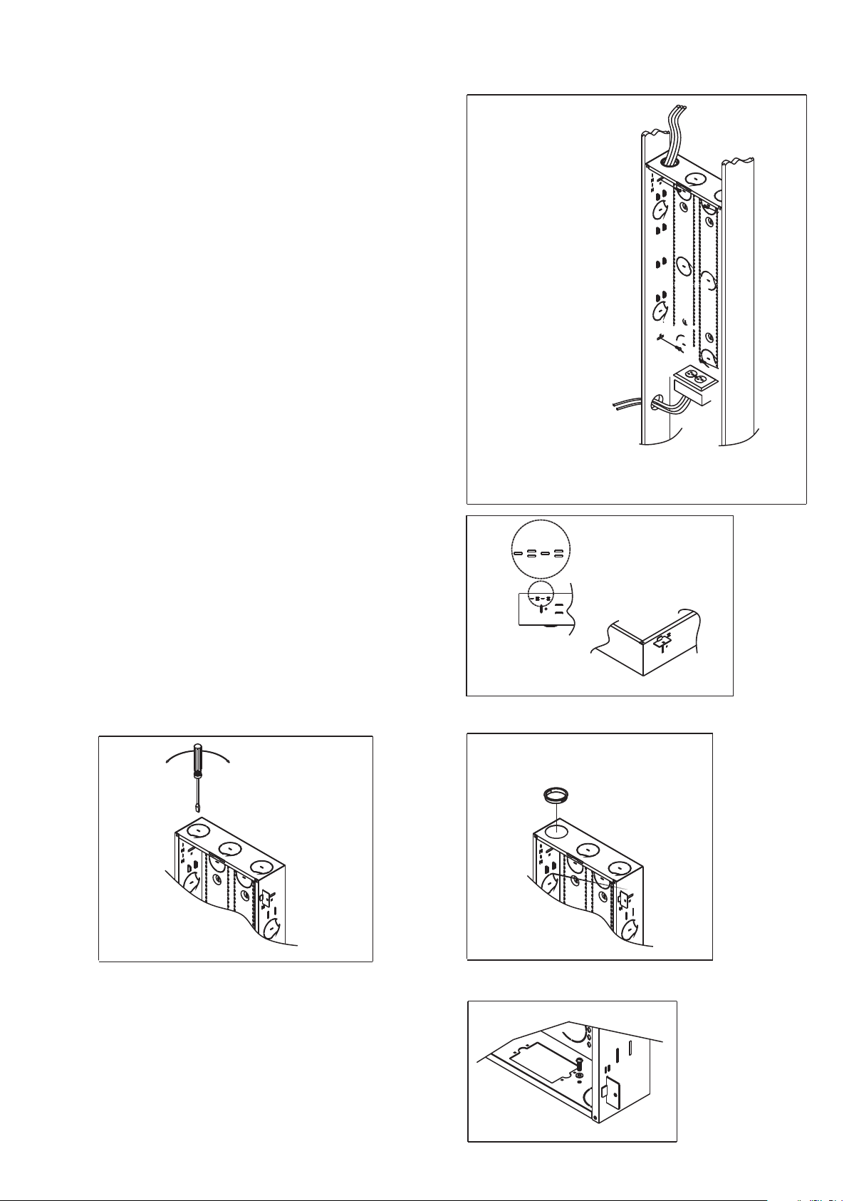
Mounting the enclosure: (see Fig. 1)
1. Using the mounting tabs or side slots to mount the
enclosure between the stubs, or using mounting holes
provided in the back of the unit for surface mounting.
Note - Be sure to leave enough space both on the top
and bottom of the unit for wire routing and the "UP"
arrow should face to the top.
2. When using the side slots, position the enclosure with
the front to protrude beyond the wallboard surface,
which will match the finished wall. Mark the center
of the mounting slots, this allows for further adjustment
to match the finished wall. Drill pilot holes and install
the enclosure with wood screws. When using the
mounting tabs, select the proper holes (A-5/8", B-1/2"
or C-3/8") for wallboard. When using the mounting
holes, attach the unit to the wall with screw anchors
recommended to support the weight of the enclosure
and variety of modules.
Remove the knockouts for wiring: (see Fig. 2)
Remove the knockouts which can be found on the top,
bottom, sides and back of the enclosure as needed for
wiring. Insert a screwdriver into the slot and bend to
break the knockout. Insert the plastic grommets in the
opening to protect cables from being damaged.
B - 1/2"
C - 3/8"
A- 5/8"
GN D
Page 2
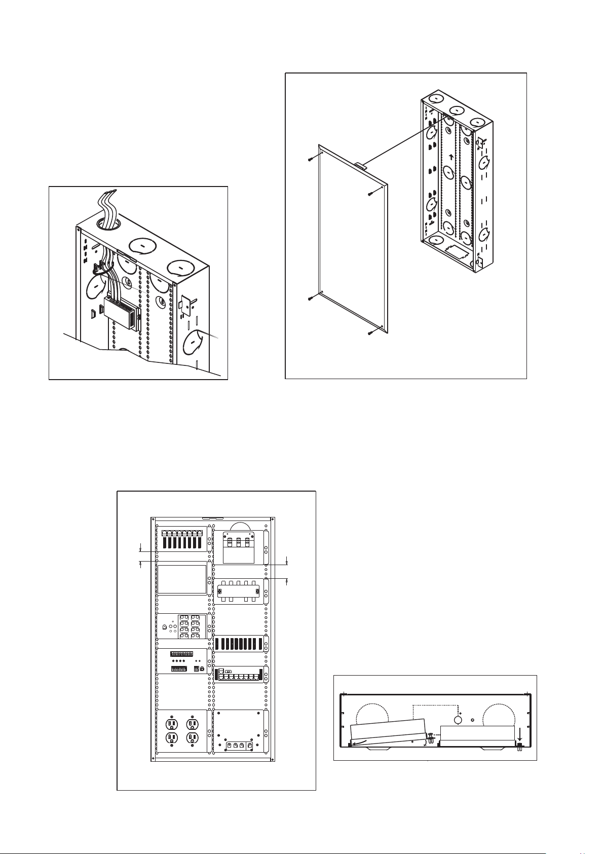
Installing the cover: (see Fig. 4)
Hook the cover on the enclosure then screw it via
mounting holes on the cover.
Wire ties: (see Fig. 5)
Using the provided wire ties to group and attach
UP
the wires at the side grids of the enclosure.
Fig. 5
Fig. 4
Module Installation: (see Fig. 6)
There are many kinds of modules available to build up the HWS. To install the module, simply insert tabs
to the cap located on the rail of the enclosure. Press the fastener to lock the module at the desired position.
For easily wire routing, 1.5" interval and 2" interval is recommended
for data/voice modules and video modules respectively.
Patch Panel Module
HPp-1008EmCom
FROM
LOCATIO N
1. 5 in
EmCom
Audio Distribution
Module
HAa-1016
EmCom
6
3
5
2
POWE R
FROM S OU R CE
L
SENSI TIV IT Y
ADJUST ME NT
From Location
1
Sensitivity Adjustment
1 2
4
LOCATIO N
TO
5 Port Etherent H UB HUb-1005
L L
R
32
To Source
43
1
R
3
R
5
R
R
IR Distribution Module
7
2
LL
4
6
LL
8
L7L
4
ACTIVIT Y
EXPANS IO N
OUTPUT
AC Power Module HPm-1004
8
EmCom
1 To 8 Video Splitter M odule
HVs-1008
OUT
OUT
OUTOUT
IN
OUT
OUT
OUTOUT
R
R
TO
LOCATIO N
R
TO LOCA TIO NS
EmCom
Telecom Distribution module
R
FROM S OU R CE
HIr-1004
1
ON
POWER
12VDC
SECUR IT Y
RJ31X
FROM S OU R CE
EmCom
HTe-1008
8
4
7
3
6
2
5
EmCom
HBg-1008
Bridged Telecom Module
ON
OFF
TO LOCA TIO NS
50W DC P ower s upply
HDp-1060
DC PO WE R O UT PU T
DC 7.5V
DC 12VDC 12VDC 12V
2. 0 in
EXPANS IO N
OUTPUT
EXPANS IO N
OUTPUT
1
EmCom
POWER
12VDC
EmCom
Fig. 6
 Loading...