

Page 1
BATTERY LIFE
Low Battery - When the battery is below the level
required for the LanMaster 30 to operate properly, the
“SIGNAL” indicator blinks on and off while a test is being
conducted.
APPLICATIONS
Moves, Adds and Changes - Reduce risk of equipment
damage by identifying correct outlet for connecting
telephone and network devices.
Installation - Verify physical layer connectivity to the farend equipment.
Trouble Calls - Reduce troubleshooting time by
ensuring the connection is correct and outlet is
functional. Prevent damage to sensitive test equipment
by identifying outlet type before running tests.
Telecom System Management - Locate expensive
unused analog phone circuits for reassignment or
termination.
Network Management - Identify Ethernet Link data rate
(10Mbps or 100Mbps) and support for auto-negotiation.
ETHERNET LINK SIGNAL OVERVIEW
Three different signals can be used to establish an
Ethernet Link: a Link Code Word, an NLP or an MLT-3
waveform. The Link Code Word is specific in both Link
speed and duplex mode. The NLP is specific in speed
(10Mbps) but ambiguous in duplex mode (half or full).
The MLT-3 waveform is also specific in speed
(100Mbps) but ambiguous in duplex mode. Duplex
modes for equipment that use NLP or MLT-3 signaling
must be carefully managed to ensure proper Link
operation.
WARRANTY
Psiber Data Systems Inc. warrants that the product shall be free from defects in
parts or workmanship for a period of 12 months from the date of purchase if used in
accordance with Psiber Data Systems Inc. operating specifications.
THIS IS THE ONLY WARRANTY MADE BY Psiber Data Systems Inc. AND
IS EXPRESSLY MADE IN LIEU OF ALL OTHER WARRANTIES EXPRESSED OR
IMPLIED, INCLUDING BUT NOT LIMITED TO ANY IMPLIED WARRANTIES OF
MERCHANTABILITY OR FITNESS FOR ANY PARTICULAR PURPOSE.
Should any parts or workmanship prove defective, Psiber Data Systems Inc. will
repair or replace at Psiber Data Systems’ option, at no cost to the Buyer except for
shipping costs from the Buyer’s location to Psiber Data Systems Inc. This is Buyer’s
SOLE AND EXCLUSIVE REMEDY under this Agreement. This warranty does not apply
to products which have been subject to neglect, accident or improper use, or to units
which have been altered or repaired by other than an authorized repair facility.
Return of Equipment - To return a product to Psiber Data Systems Inc., first
obtain a Return Authorization number from our Customer Service by calling 619-287-
9970. The RA# must be clearly marked on the shipping label, or the package will not be
accepted by Psiber Data Systems Inc. See sample label below.
To: Psiber Data Sytems Inc.
7075-K Mission Gorge Road
San Diego, CA 92120
RA# XXXXXXXX
LanMaster, psiber and the Psiber logo are trademarks of Psiber Data
Systems Inc. Copyright 1999 Psiber Data Systems Inc. All rights reserved.
Part No. 1005-0300-0000 Rev B
LL
L
LL
MM
ANAN
AN
ANAN
ASTERASTER
M
ASTER
ASTERASTER
MM
USER’S GUIDE
30 30
30
30 30
Page 2
BOX CONTENTS
•
LanMaster 30 Outlet Identifier• RJ-45 Coupler
•
9 Volt Alkaline Battery
•
User Guide
BATTERY
The LanMaster 30 operates on one 9 volt alkaline
battery. Remove the battery cover
at the bottom of the unit and insert
the battery with the terminal
orientation as shown. Battery
polarity is marked on the back of
the battery cover and inside the
battery well for reference.
TECHNICAL OVERVIEW
The LanMaster 30 Outlet Identifier is a comprehensive signal detection, measurement and identification
device. The unit measures signals on every combination
of wire pairs in a four (RJ-11), six (RJ-12) or eight (RJ-
45) wire outlet or plug. The measurements are
compared to known signal parameters for telecommunication and data communication equipment and reported
to the user by illumination of equipment-type LEDs. A
“SIGNAL” indicator is provided to warn when signals are
present at the outlet or plug that do not correspond to
known equipment parameters. A “NO LINK” indicator is
illuminated when no signals are detected on any of the
wires.
The LanMaster 30 conducts a three step test that is
completed in less than six seconds. The first test
measures voltages on all wire pairs and identifies an
Analog, PBX or ISDN telephone circuit. The second test
measures Standard (10baseT) and Fast (100baseTX)
Ethernet Link Signals and identifies the operating mode
of the far-end equipment. The third test transmits a
Token Ring voltage that causes the unit to be inserted in
to a ring and then measures the ring speed (4MHz or
16MHz).
OPERATION
Insert the LanMaster 30 plug end in to the RJ-45
jack of a wall outlet, or attach to a 4-wire, 6-wire or 8wire patch cable with the RJ-45 coupler provided. Press
and hold the “TEST” button.
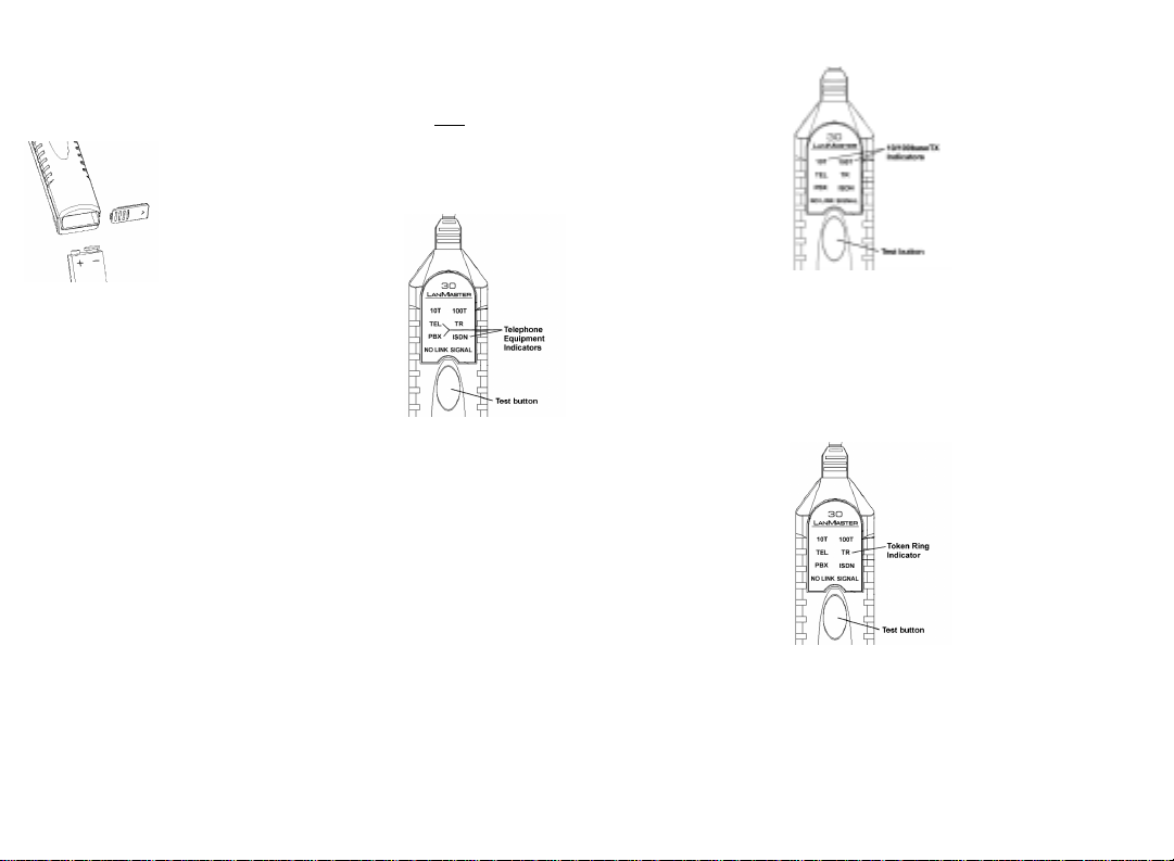
Telephone Circuit Identification
While the unit is conducting the telephone test, the
“TEL” indicator will blink on and off. During the first two
seconds of the test, each
combination (64 total) of two
wires are scanned for signals
and each voltage measurement is recorded. If
telephone line voltage is
detected on wire pair 4,5 and
no signals are present on any
other pair, the “TEL” indicator
is illuminated showing that an
analog phone line has been detected. If 24VDC or
48VDC is detected between wire pairs 3,6 and 4,5 (S/T
interface) or sealing current on pair 4,5 (U interface), the
“ISDN” indicator is illuminated showing that an ISDN
circuit has been identified. If appropriate voltage levels
are detected on one or more wire pairs, the “PBX”
indicator is illuminated showing that a PBX type switch
or a multiple line phone circuit has been detected.
NOTE: If voltages above expected levels are measured,
the “SIGNAL” indicator is lit showing that an unknown
and potentially damaging voltage is present. The user
should identify the equipment installed at the far-end
prior to connecting any devices to the outlet under test.
10baseT/100baseTX Link Identification
While the unit is conducting the 10baseT/100baseTX
Link test, the “10T” and “100T” indicators will blink on
and off. If an MLT-3 waveform is detected or a Link
Code Word is decoded for 100baseTX operation, the
“100T” indicator is illuminated showing a 100baseTX
connection. If a Normal Link Pulse (NLP) is detected or
a Link Code Word is decoded for 10baseT operation,
operation. The LanMaster 30 does not test 100baseT4.
The “SIGNAL” indicator will be illuminated if a Link Code
Word is detected that is invalid or contains a reported
Fault or the MLT-3 waveform frequency is incorrect.
TT
okok
en Ring Link Identificaen Ring Link Identifica
T
ok
en Ring Link Identifica
TT
okok
en Ring Link Identificaen Ring Link Identifica
While the unit is conducting the Token Ring Link
test the “TR” indicator will blink on and off. The Model 30
16MHz ring speed is measured. The “SIGNAL” indicator
is lit if the current is below the minimum value, indicating
an open wire, or the speed of the ring is not 4MHz or
16MHz.
No LinkNo Link
No Link
No LinkNo Link
When no signals are detected during any of the three
previous tests, the “NO LINK” indicator is illuminated.
Total time to complete all tests is less than six seconds.
the “10T” indicator is
illuminated. If a Link Code
Word is decoded for 10/100
auto-negotiation, both the
“10T” and “100T” indicators
are illuminated showing that
the far end equipment is
capable of auto-negotiating
to either the 10baseT or
100baseTX mode of
tiontion
tion
tiontion
transmits the standard Token
Ring phantom voltage
between wire pairs 3,6 and
4,5. If the measured current
is within the correct range,
the voltage is maintained to
allow the unit to be inserted
into the ring. Once inserted in
the ring, the “TR” indicator is
illuminated if a 4MHz or
 Loading...