

Page 1

Leitor Fixo
Magellan 3200 VSi
O leitor Magellan 3200 VSi possui um excelente
desempenho em leituras de codificações 1D, GS1 Databar
e 2D – QR Code, permitindo que qualquer código de barra
seja lido já na primeira passagem seja por meio de
apresentação ou passagem, em qualquer direção.
Conheça o Magellan 3200 VSi.
www.bztech.com.br
Page 2

Magellan
TM
3200
Product Reference Guide
Page 3

Datalogic ADC, Inc.
959 Terry Street
Eugene, OR 97402
USA
Telephone: (541) 683-5700
Fax: (541) 345-7140
© 2010-2014 Datalogic ADC, Inc.
An Unpublished Work - All rights reserved. No part of the contents of thi
s documentation or the procedures described therein may
be reproduced or transmitted in any form or by any means without prior written permission of Datalogic ADC, Inc. or its subsidiaries or affiliates ("Datalogic" or "Datalogic ADC"). Owners of Datalogic products are hereby granted a non-exclusive, revocable license
to reproduce and transmit this documentation for the purchaser's own internal business purposes. Purchaser shall not remove or
alter any proprietary notices, including copyright notices, contained in this documentation and shall ensure that all notices appear
on any reproductions of the documentation.
re pr
Should future revisions of this manual be published, you can acqui
inted versions by contacting your Datalogic representative.
Electronic versions may either be downloadable from the Datalogic website (www.datalogic.com) or provided on appropriate
media. If you visit our website and would like to make comments or suggestions about this or other Datalogic publications, please
let us know via the "Contact Datalogic" page.
Disclaimer
Datalogic has taken reasonable measures to provide information in this manual
that is comp
lete and accurate, however, Datalogic
reserves the right to change any specification at any time without prior notice.
Datalogic and the Datalogic logo are registered trademarks of Datalogic S.p
.A. in many countries, including the U.S.A. and the E.U.
All other brand and product names may be trademarks of their respective owners.
Magellan is a registered trademark of Datalogic ADC, Inc. in many countries, including the U.S.A. and the E.U.
This product may be covered by one or more of the following patents:
Utility patents: EP1307854B1 ; EP1425704B1 ; GB2346474 ; GB2346475 ; US5481098 ; US5837983 ; US6012639 ; US6073849 ;
US6129279
; US6578765 ; US6705527 ; US6877663 ; US7201322 ; US7204422
Additional patents pending.
Page 4

Table of Contents
Chapter 1. Getting Started............................................................................................................................................................... 1
About This Manual .................................................................................................................................................................................................................1
Manual Conventions ................................................................................................................................................................................................... 1
Connecting the Scanner ....................................................................................................................................................................................................... 2
Error Codes ................................................................................................................................................................................................................................4
Mount Installation ..................................................................................................................................................................................................................4
Wall Mount ..................................................................................................................................................................................................................... 6
Countertop Mount ....................................................................................................................................................................................................... 6
LED and Beeper Indicators ..................................................................................................................................................................................................7
Programming ...........................................................................................................................................................................................................................8
Using the Programming Bar Codes ....................................................................................................................................................................... 8
Resetting the Standard Product Defaults ......................................................................................................................................................................8
Data Matrix Programming Labels .....................................................................................................................................................................................8
Bar Code Mask ..........................................................................................................................................................................................................................9
Going Green .................................................................................................................................................................................................................10
LED Class ................................................................................................................................................................................................................................. 10
Chapter 2. General Features .......................................................................................................................................................... 11
Double Read Timeout for Linear Labels ...................................................................................................................................................................... 11
Double Read Timeout for 2D Labels ............................................................................................................................................................................. 13
Scanner Button Options .................................................................................................................................................................................................... 14
Camera Button Mode ......................................................................................................................................................................................................... 15
Auto Cell Phone Mode ....................................................................................................................................................................................................... 16
Auto Cell Phone Mode Enable ...............................................................................................................................................................................16
LED Level ................................................................................................................................................................................................................................. 17
Auxiliary Port Mode ............................................................................................................................................................................................................. 18
Auxiliary Port Baud Rate .................................................................................................................................................................................................... 19
Productivity Index Reporting (PIR) ................................................................................................................................................................................ 20
Sleep Mode ............................................................................................................................................................................................................................ 21
LED and Beeper Indicators ............................................................................................................................................................................................... 23
Power On Alert ............................................................................................................................................................................................................23
External Read Indicator (ERI) Active State High ..............................................................................................................................................23
ERI Timeout ..................................................................................................................................................................................................................24
Good Read: When to Indicate ................................................................................................................................................................................25
Good Read Beep Control .........................................................................................................................................................................................26
Good Read Beep Frequency ...................................................................................................................................................................................26
Good Read Beep Length ..........................................................................................................................................................................................27
Good Read Beep Volume ........................................................................................................................................................................................28
Scanning Features ............................................................................................................................................................................................................... 29
Wake Up Intensity ......................................................................................................................................................................................................29
Chapter 3. Image Capture.............................................................................................................................................................. 31
Image Capture ...................................................................................................................................................................................................................... 31
How to Capture an Image .......................................................................................................................................................................................31
Image Capture to a microSD Card by Scanning a Special Label ....................................................................................................31
Image Capture to the Host by Host Command .....................................................................................................................................32
Image Compression ............................................................................................................................................................................................................ 33
Image Format ........................................................................................................................................................................................................................ 33
Image Size .............................................................................................................................................................................................................................. 34
Image Brightness ................................................................................................................................................................................................................. 35
Image Contrast ..................................................................................................................................................................................................................... 35
Chapter 4. Interface Related Features .......................................................................................................................................... 37
Interface Selection ............................................................................................................................................................................................................... 39
Interface Features ................................................................................................................................................................................................................ 41
Obey/Ignore Host Commands .....................................................................................................................................................................41
Product Reference Guide i
Page 5

Host Transmission Buffers ............................................................................................................................................................................. 42
RS-232 Interface Features ....................................................................................................................................................................................... 43
Hardware Flow Control .................................................................................................................................................................................. 45
Intercharacter Delay ........................................................................................................................................................................................ 46
Software Flow Control .................................................................................................................................................................................... 47
Host Echo ............................................................................................................................................................................................................48
Host Echo Quiet Interval ................................................................................................................................................................................49
Signal Voltage: Normal/TTL .......................................................................................................................................................................... 50
RS-232 Invert ...................................................................................................................................................................................................... 51
Beep on ASCII BEL ............................................................................................................................................................................................ 51
Beep on Not on File ......................................................................................................................................................................................... 52
ACK NAK Options .............................................................................................................................................................................................53
ACK Character .................................................................................................................................................................................................... 54
NAK Character ...................................................................................................................................................................................................54
Retry on ACK NAK Timeout .......................................................................................................................................................................... 55
ACK NAK Timeout Value ................................................................................................................................................................................ 55
ACK NAK Retry Count .....................................................................................................................................................................................56
ACK NAK Error Handling .......................................................................................................................................................................................... 57
Transmission Failure Indication ..................................................................................................................................................................58
Single Cable RS-232 .............................................................................................................................................................................................................58
Single Cable RS-232 Options ................................................................................................................................................................................. 58
Single Cable RS-232 RTS CTS Selection ..............................................................................................................................................................59
Single Cable RS-232 Use BCC .................................................................................................................................................................................60
Single Cable RS-232 Use ACK/NAK ......................................................................................................................................................................60
Single Cable RS-232 Use STX .................................................................................................................................................................................61
Set Single Cable RS-232 STX Character .............................................................................................................................................................. 61
Single Cable RS-232 Use ETX .................................................................................................................................................................................62
Set Single Cable RS-232 ETX Character .............................................................................................................................................................. 62
Single Cable Pacesetter Plus .................................................................................................................................................................................. 63
Single Cable Datalogic Extensions ......................................................................................................................................................................63
USB-OEM Interface Features .................................................................................................................................................................................. 64
USB-OEM Device usage .................................................................................................................................................................................64
IBM ..................................................................................................................................................................................................................................64
IBM Transmit Labels in Code 39 Format ..................................................................................................................................................64
Keyboard Wedge .......................................................................................................................................................................................................65
USB Keyboard .............................................................................................................................................................................................................. 65
Caps Lock State .................................................................................................................................................................................................67
USB COM Interface Set-up .................................................................................................................................................................................................71
Chapter 5. Data Editing.................................................................................................................................................................. 73
Data Editing Overview ........................................................................................................................................................................................................73
Please Keep In Mind... ............................................................................................................................................................................................... 73
Global Prefix/Suffix ..............................................................................................................................................................................................................74
AIM ID .......................................................................................................................................................................................................................................75
Label ID ....................................................................................................................................................................................................................................76
Case Conversion ...................................................................................................................................................................................................................82
Character Conversion .........................................................................................................................................................................................................83
Chapter 6. Symbologies................................................................................................................................................................. 85
UPC-A ........................................................................................................................................................................................................................................85
Disable/Enable UPC-A ..............................................................................................................................................................................................85
Check Digit Transmission ........................................................................................................................................................................................86
Number System Transmission ..............................................................................................................................................................................86
Expand UPC-A to EAN-13 ........................................................................................................................................................................................ 87
UPC-E ........................................................................................................................................................................................................................................88
Disable/Enable UPC-E ..............................................................................................................................................................................................88
Check Digit Transmission ........................................................................................................................................................................................88
Number System Digit ............................................................................................................................................................................................... 89
Expand to UPC-E to UPC-A ..................................................................................................................................................................................... 89
Expand UPC-E to EAN13 .......................................................................................................................................................................................... 90
GTIN ................................................................................................................................................................................................................................91
Expand UPC/EAN to GTIN .......................................................................................................................................................................................91
ii
Magellan
TM
3200VSi
Page 6

EAN-13 ..................................................................................................................................................................................................................................... 92
Disable/Enable EAN-13 ............................................................................................................................................................................................92
Check Digit Transmission ........................................................................................................................................................................................92
EAN-13 Flag 1 Character ..........................................................................................................................................................................................93
ISBN .................................................................................................................................................................................................................................93
EAN-8 ........................................................................................................................................................................................................................................ 94
Disable/Enable EAN-8 ...............................................................................................................................................................................................94
Check Digit Transmission ........................................................................................................................................................................................94
EAN Two-Label ...................................................................................................................................................................................................................... 96
EAN Two-Label Combined Transmission .................................................................................................................................................................... 96
Price Weight Check Digit .................................................................................................................................................................................................. 97
Add-ons ................................................................................................................................................................................................................................... 98
GS1 DataBar Omnidirectional / Stacked Omnidirectional .................................................................................................................................. 100
Disable/Enable GS1 DataBar Omnidirectional .............................................................................................................................................100
UCC/EAN 128 Emulation ...................................................................................................................................................................................... 100
GS1 DataBar Expanded / Expanded Stacked ...........................................................................................................................................................101
Disable/Enable GS1 DataBar Expanded .......................................................................................................................................................... 101
GS1-128 Emulation ................................................................................................................................................................................................. 101
Length Control ......................................................................................................................................................................................................... 102
GS1 DataBar Expanded Length 1, Length 2 Programming Instructions ............................................................................................. 102
Coupon Read Control ............................................................................................................................................................................................ 103
GS1 DataBar Limited ......................................................................................................................................................................................................... 104
Disable/Enable GS1 DataBar Limited ............................................................................................................................................................... 104
GS1-128 Emulation ................................................................................................................................................................................................. 104
Code 39 ..................................................................................................................................................................................................................................105
Disable/Enable Code 39 ........................................................................................................................................................................................ 105
Check Character Calculation ............................................................................................................................................................................... 105
Check Character Transmit .................................................................................................................................................................................... 106
Start/Stop Characters ............................................................................................................................................................................................ 106
Code 39 Full ASCII ................................................................................................................................................................................................... 107
Length Control ......................................................................................................................................................................................................... 108
Code 39 Length 1, Length 2 Programming Instructions ..........................................................................................................................108
Code 32 Italian Pharmacode .......................................................................................................................................................................................... 109
Disable/Enable Code 32 Italian Pharmacode ................................................................................................................................................ 109
Start/Stop Characters ............................................................................................................................................................................................ 109
Code 32 Italian Pharmacode — continued ...................................................................................................................................................110
Check Character Transmit .................................................................................................................................................................................... 110
Code 128 ............................................................................................................................................................................................................................... 111
Disable/Enable Code 128 ..................................................................................................................................................................................... 111
Disable/Enable EAN 128 ....................................................................................................................................................................................... 111
Transmit Function Characters ............................................................................................................................................................................112
Length Control ......................................................................................................................................................................................................... 113
Code 128 Length 1, Length 2 Programming Instructions ........................................................................................................................ 113
Code 128 Conversion to Code 39 ...................................................................................................................................................................... 114
Interleaved 2 of 5 ............................................................................................................................................................................................................... 114
Disable/Enable Interleaved 2 of 5 ..................................................................................................................................................................... 114
Check Digit Calculation ......................................................................................................................................................................................... 115
Check Digit Transmit .............................................................................................................................................................................................. 115
Length Control ......................................................................................................................................................................................................... 116
Interleaved 2 of 5 Length 1, Length 2 Programming Instructions ........................................................................................................ 116
Codabar ...........................................................................................................................................................
Disable/Enable Codabar ....................................................................................................................................................................................... 117
Check Character Verification ............................................................................................................................................................................... 117
Check Character Transmit .................................................................................................................................................................................... 118
Length Control ......................................................................................................................................................................................................... 119
Codabar Length 1, Length 2 Programming Instructions .......................................................................................................................... 119
Start/Stop Character Type .................................................................................................................................................................................... 120
Start/Stop Character Transmission ................................................................................................................................................................... 120
Start/Stop Character Match ................................................................................................................................................................................. 121
Code 93 ..................................................................................................................................................................................................................................121
Disable/Enable Code 93 ........................................................................................................................................................................................ 121
Length Control ......................................................................................................................................................................................................... 122
......................................................................1
17
Product Reference Guide iii
Page 7

Code 93 Length 1, Length 2 Programming Instructions ...........................................................................................................................122
MSI .......................................................................................................................................................................................................................................... 123
Disable/Enable MSI .................................................................................................................................................................................................123
MSI Check Character Transmit ............................................................................................................................................................................123
MSI Check Character Calculation .......................................................................................................................................................................124
MSI Number of Check Characters ......................................................................................................................................................................124
MSI Length Control .................................................................................................................................................................................................125
MSI Length 1, Length 2 Programming Instructions ....................................................................................................................................125
Chapter 7. 2D Symbologies ......................................................................................................................................................... 127
2D Symbologies ................................................................................................................................................................................................................. 127
PDF 417 ........................................................................................................................................................................................................................128
Disable/Enable PDF 417 ...............................................................................................................................................................................128
Allow Zero Length PDF 417 Reading ......................................................................................................................................................128
Length Control ................................................................................................................................................................................................129
PDF 417 Length 1, Length 2 Programming Instructions .................................................................................................................130
Micro PDF 417 ...........................................................................................................................................................................................................131
Disable/Enable Micro PDF 417 ..................................................................................................................................................................131
Length Control ................................................................................................................................................................................................132
Micro PDF 417 Length 1, Length 2 Programming Instructions .....................................................................................................133
Datamatrix ..................................................................................................................................................................................................................134
Disable/Enable Datamatrix .........................................................................................................................................................................134
Length Control ................................................................................................................................................................................................135
Datamatrix Length 1, Length 2 Programming Instructions ............................................................................................................136
QR Code .......................................................................................................................................................................................................................137
Disable/Enable QR Code ..............................................................................................................................................................................137
Length Control ................................................................................................................................................................................................138
QR Code Length 1, Length 2 Programming Instructions ................................................................................................................139
Maxicode .....................................................................................................................................................................................................................140
Disable/Enable Maxicode ............................................................................................................................................................................140
Length Control ................................................................................................................................................................................................141
Maxicode Length 1, Length 2 Programming Instructions ..............................................................................................................142
Aztec .............................................................................................................................................................................................................................143
Disable/Enable Aztec ....................................................................................................................................................................................143
Length Control ................................................................................................................................................................................................144
Aztec Length 1, Length 2 Programming Instructions .......................................................................................................................145
Composite Labels ....................................................................................................................................................................................................146
Disable/Enable GS1 DataBar Omnidirectional 2D Component ....................................................................................................146
Disable/Enable GS1 DataBar Expanded 2D Component .................................................................................................................146
Disable/Enable GS1 DataBar Limited 2D Component ......................................................................................................................147
Chapter 8. Advanced Decoding Features................................................................................................................................... 149
Inverse Label Reading ...................................................................................................................................................................................................... 149
UPC/EAN Quiet Zone ....................................................................................................................................................................................................... 150
Chapter 9. References .................................................................................................................................................................. 151
Global Prefix/Suffix ........................................................................................................................................................................................................... 152
Label ID ................................................................................................................................................................................................................................. 153
Length Control ..........................................................................................................................................................................................................154
Length 1, Length 2 Programming Instructions .............................................................................................................................................154
Appendix A. Product Specifications....................................................................................................................... 155
Optical and Read Performance Parameters ............................................................................................................................................................. 155
Scanner Dimensions ......................................................................................................................................................................................................... 155
Physical Properties ............................................................................................................................................................................................................ 156
Electrical Parameters ........................................................................................................................................................................................................ 156
Environmental Parameters ............................................................................................................................................................................................ 156
Other Parameters .............................................................................................................................................................................................................. 156
Appendix B. Cable Pinouts...................................................................................................................................... 157
Standard Cable Pinouts (Primary Interface Cables) .............................................................................................................................................. 157
iv
Magellan
TM
3200VSi
Page 8

Appendix C. Alpha-Numeric Pad ............................................................................................................................ 159
Appendix D. Factory Default Settings ................................................................................................................... 161
Factory Defaults by Interface ......................................................................................................................................................................................... 161
Appendix E. Keyboard Function Key Mappings.................................................................................................... 167
Keyboard Model Cross Reference ................................................................................................................................................................................167
Appendix F. Host Commands ................................................................................................................................. 175
Accepting RS-232 Commands ......................................................................................................................................................................................175
Appendix G. Sample Symbols................................................................................................................................. 177
1D Symbol Samples .......................................................................................................................................................................................................... 177
2D Sample Symbols .......................................................................................................................................................................................................... 179
Composite Sample Symbols ..........................................................................................................................................................................................180
Appendix H. microSD Card ..................................................................................................................................... 181
microSDHC Compatibility ............................................................................................................................................................................................... 181
microSD Card Insertion .................................................................................................................................................................................................... 181
microSD Card Removal .........................................................................................................................................................................................182
Autorun File Processing .................................................................................................................................................................................................. 182
microSD Function Summary .......................................................................................................................................................................................... 182
microSD Function Details ...............................................................................................................................................................................................183
From Scanner to microSD Card .......................................................................................................................................................................... 183
Capture and save an image to a microSD card by scanning a label. .......................................................................................... 183
Export a Configuration file from the Scanner to the microSD card ............................................................................................183
Export Scanner Status to microSD card ................................................................................................................................................. 184
From microSD Card to Scanner .......................................................................................................................................................................... 184
Application code load to scanner ............................................................................................................................................................ 184
Configuration load to scanner .................................................................................................................................................................. 185
Appendix I. Handheld Data Format Requirements............................................................................................... 187
Handheld Data Format Requirements General ............................................................................................................................................ 187
Datalogic Handheld Data Format Requirements ........................................................................................................................................ 188
RSS-14 ................................................................................................................................................................................................................ 188
RSS Expanded ................................................................................................................................................................................................. 188
UPC-A ................................................................................................................................................................................................................. 188
UPC-A with 2-Digit Supplemental ........................................................................................................................................................... 188
UPC-A with 5-Digit Supplemental ........................................................................................................................................................... 188
UPC-A with Code 128 Supplemental .....................................................................................................................................................188
UPC-E ................................................................................................................................................................................................................. 189
UPC-E with 2-Digit Supplemental ...........................................................................................................................................................190
UPC-E with 5-Digit Supplemental ...........................................................................................................................................................190
UPC-E with Code 128 Supplemental ...................................................................................................................................................... 190
EAN-8 ................................................................................................................................................................................................................. 191
EAN-8 with 2-Digit Supplemental ........................................................................................................................................................... 191
EAN-8 with 5-Digit Supplemental ........................................................................................................................................................... 191
EAN-8 with Code 128 Supplemental ...................................................................................................................................................... 191
EAN-13 ............................................................................................................................................................................................................... 191
EAN-13 with 2-Digit Supplemental ......................................................................................................................................................... 191
EAN-13 with 5-Digit Supplemental ......................................................................................................................................................... 191
EAN-13 with Code 128 Supplemental ...................................................................................................................................................192
Code 39 ............................................................................................................................................................................................................. 192
Code 39-Pharmacode .................................................................................................................................................................................. 192
I 2 of 5 ................................................................................................................................................................................................................. 192
Codabar ............................................................................................................................................................................................................. 193
Code 128 ........................................................................................................................................................................................................... 193
MSI ...................................................................................................................................................................................................................... 194
Code 93 ............................................................................................................................................................................................................. 194
PDF417 .............................................................................................................................................................................................................. 194
AIM Formats .............................................................................................................................................................................................................. 195
Product Reference Guide v
Page 9

UPC-A .................................................................................................................................................................................................................195
UPC-E ..................................................................................................................................................................................................................195
EAN-13 ...............................................................................................................................................................................................................195
EAN-8 ..................................................................................................................................................................................................................195
2-Digit Supplemental ...................................................................................................................................................................................195
5-Digit Supplemental ...................................................................................................................................................................................196
Code 128 Supplemental ..............................................................................................................................................................................197
Bookland ...........................................................................................................................................................................................................197
Code 39 ..............................................................................................................................................................................................................197
Codabar .............................................................................................................................................................................................................197
MSI .......................................................................................................................................................................................................................198
Code 93 ..............................................................................................................................................................................................................198
RSS-14 .................................................................................................................................................................................................................199
RSS Expanded ..................................................................................................................................................................................................199
I 2 of 5 .................................................................................................................................................................................................................199
Code 128 / EAN128 ........................................................................................................................................................................................200
PDF417 ...............................................................................................................................................................................................................200
“Unknown” AIM ID (an AIM ID which is not specified above) .......................................................................................................200
vi
Magellan
TM
3200VSi
Page 10

The Magellan
counter retail checkout environments where there is a relatively high number of transactions
with a fairly small number of items per transaction. The scanner has a reduced footprint, allowing more room for item merchandising of high margin impulse items clustere
P. O . S .
About This Manual
This manual provides advanced user information, including connection, programming, product
and cable specifications, and other useful references. For additional information, such as installation, maintenance, troubleshooting and warranty information, see the Quick Reference Guide
(QRG). Copies of other publications for
website listed on the back cover of this manual.
Chapter 1
Getting Started
TM
3200VSi On-Counter Vertical Presentation Scanner is designed for small
d around the
this product are downloadable free of charge from the
On leaving the factory, units are programmed for the most common terminal and communica
tions settings. If you need to change these settings, custom programming can be accomplished
scanning the bar codes in this guide.
by
Bold text and a yellow-highlighted background indicates the most common default setting for a
featur
e/option.
Manual Conventions
The symbols listed below are used in this manual to notify the reader of key issues or procedures
that must be observed when using the scanner:
CAUTION
NOTE
Notes contain information necessary for
properly
ing the scanner.
The CAUTION symbol advises you of
actions that c
property.
diagnosing, repairing and operat-
ould damage equipment or
-
Product Reference Guide
1
Page 11
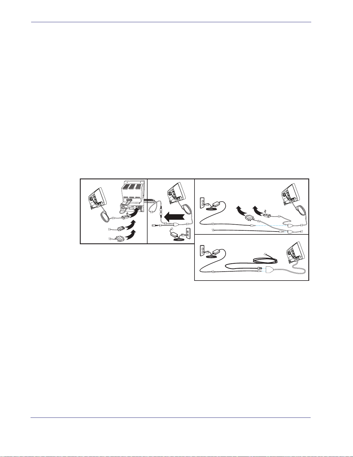
Getting Started
Connecting the Scanner
The scanner kit you ordered to match your interface should provide a compatible cable for your
installation. Alternatively, if your scanner receives Power Off the Terminal (POT) it might be
possible to connect using a cable from a previously existing installation (except for USB). If you
wish to connect using an existing cable, but cannot use POT, a short adapter cable is available.
Check with your technical support representative about compatibility before connecting. Use
the appropriate instructions below when you’re ready to connect the scanner to the terminal, PC
or other host device.
Upon completing the connection via the appropriate interface instru
the
Interface Related Features section of this manual and scan the bar code to select the correct
ctions below, proceed to
interface type.
RS-232 Serial Connection —
terminal/PC serial port via the RS-232 cable as shown in
port POT (Power Off the Terminal) to supply scanner power
(AC Adapter) as shown in
the RS-232 cable connector and the AC Adapter plug into a standard po
Figure 1
. Connecting the Scanner
a
Power Off
the Terminal
(POT)
Terminal (PC)
or...
or...
Turn off power to the terminal/PC and connect the scanner to the
Figure 1a. If the terminal will not sup-
, use the approved power supply
Figure 1b. Plug the AC Adapter barrel connector into the socket on
wer outlet.
b
B
S
U
M
B
I
2
3
2
-
S
R
Keyboard
Wedge
c
Keyboard W edge, RS-232
and USB Cables
Powered by AC Adapter
To T erminal (PC)
R
U
S
-
S
2
3
B
2
Other Non-POT Cables
Powered by AC Adapter
via short adapter cable
To T erminal (PC)
USB Connection —
USB cable for the interface type you ordered. Reference
Connect the scanner to a USB port on the terminal/PC using the correct
Figure 1.
USB installations may require a power connection via an
approved A/C Adapt
er as shown in
Figure 1b or Figure 1c. For
example, this would be the case if the scanner is connected
NOTE
IBM Connection —
IBM cable. Reference
hub.
Connect the scanner to the IBM port on the terminal/PC using the correct
Figure 1.
2
along with a n
umber of other devices to a non-powered USB
MagellanTM 3200VSi
Page 12
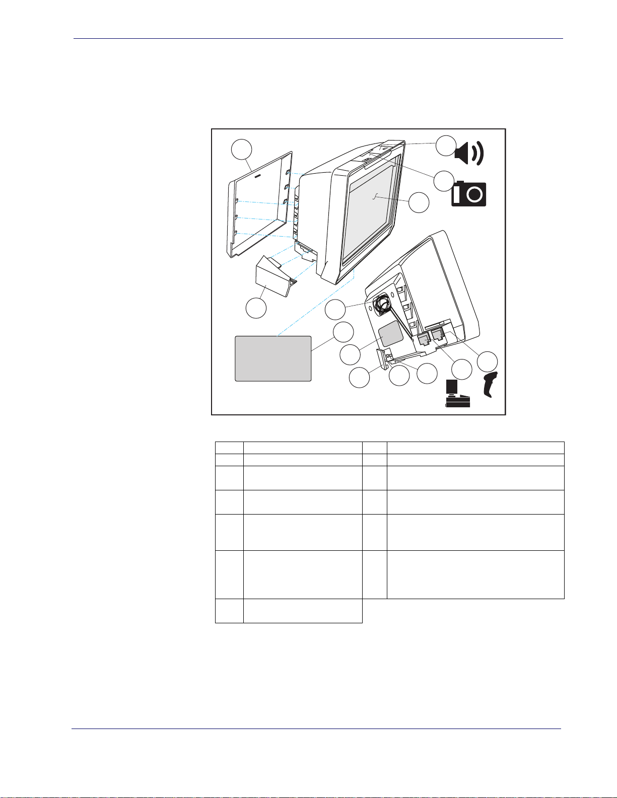
Connecting the Scanner
Keyboard Wedge Connection —
Before connection, turn off power to the terminal/PC. The Keyboard Wedge cable has a ‘Y’ connection from the scanner. Connect the female to the male end
from the
Figure 1a.
Figure 2. Labeling and Nomenclature
keyboard and the remaining end at the keyboard port at the terminal/PC. Reference
1
2
3
4
5
6
7
8
11
9
1 Back Cover 8 P/N Label
2 Scanner Push Button 9 USB/SD Cover
3 Camera Push Button 10
4 Scan Window 11
5 Cable Connector Cover 12
Checkpoint EAS Wire
Cavity Electr
6
Surveillance Antenna
Conn
ection
Serial Nu
7
bel
La
ical Article
mber/Regulatory
10
USB Service Port — On Screen Programming Tool
microSD Card Slot — Upgrade, imaging, statistics data
Host (blue) Port— POS terminal, label
pplication host download, host
ta, a
da
commands to scanner
Auxiliary (yellow) P
held scanner
13
etc.
, EAS Interlock, PIR data,
13
12
ort for RS-232 hand-
Product Reference Guide
3
Page 13
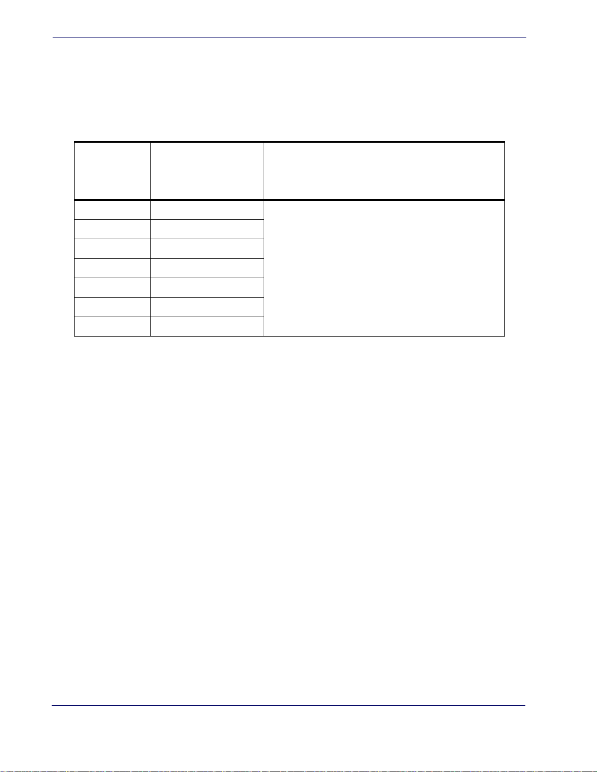
Getting Started
Error Codes
NUMBER OF
LED
FLASHES/
BEEPS
1 Configuration
2 Interface PCB
6 Main PCB
If an error is detected, the scanner will sound a long low tone (for three seconds) and flash its
LED, indicating a failure. When this occurs, press the Scanner Pushbutton to hear the error
code. If it is configured to do so, the scanner will sound a series of beeps corresponding to the
error code and/or flash its LED simultaneous to the beeps. The table below describes what these
codes mean and what action should be taken for each.
ERROR CORRECTIVE ACTION
10 Button Error
12 Imager Module
13 Software ID Failure
14 Software Fatal Fault
Mount Installation
Options for mounting the scanner to a wall or countertop include an L-Bracket or stackable
Risers (straight or tilted).
demonstrates the use of stackable Risers.
NOTE
Contact Helpdesk for assistance
Figure 3 shows the scanner being seated in an L-Bracket. Figure 4
Stackable Risers also require use of the L-Bracket in order to
securely se
at the scanner in the topmost riser.
4
MagellanTM 3200VSi
Page 14
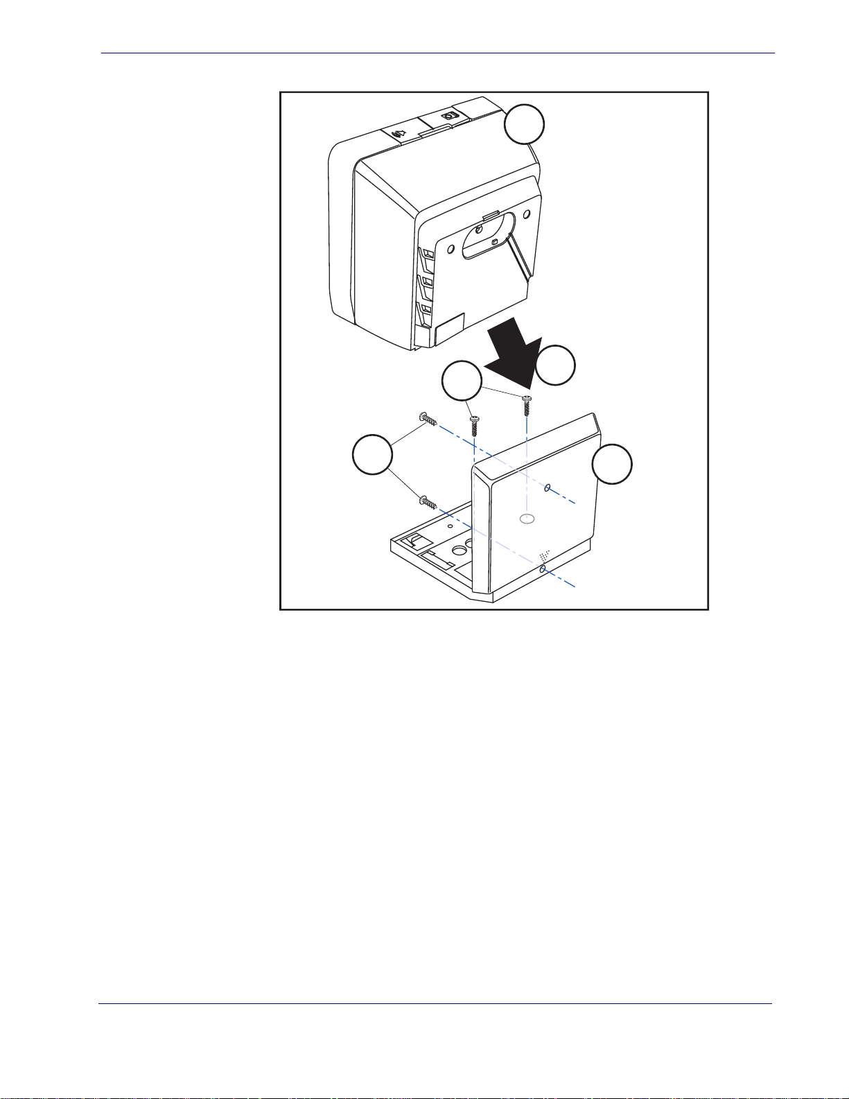
Figure 3. L-Bracket Mount
1
2
3
4
5
1. Scanner
2. L-Bracket
3. Wall Mounting Screws
4. Countertop Mounting Screws
5. Move the scanner toward the bracket in a diagonal motion to seat it.
Mount Installation
Product Reference Guide
5
Page 15

Getting Started
One Riser
Two Risers stacked. Scanner and L-Bracket have
been tilted on the top Riser.
ab
Wall Mount
Figure 4. Using the Risers
Attach the L-Bracket to the wall, securing it in the desired position with two screws through the
two holes in the back face of the L-Bracket as shown in
Head (8.2mm or 5/16” maximum head diameter) #8 scr
mounting surface material in the wall.
Countertop Mount
If using the L-Bracket alone for countertop installation, secure the bracket in place using two
screws through the bottom face of the bracket (see
the countertop by attaching two screws through its screw holes. Recommendation: Use two Pan
Head (8.2mm or 5/16” maximum head diameter) #8 s
mounting surface material in the countertop.
Risers may be stacked as shown in Figure 4b. Each riser increments the height of the mounted
scanner by 1.5” (38.1mm). Riser pieces readily snap together or apart and allo
tilt of the scanner/L-Bracket of up to 20 degrees in 5° increments.
of a tilted scanner.
Figure 3. Recommendation: Use two Pan
ew with a thread profile that suits the
Figure 3). If risers are used, secure a riser to
crew with a thread profile that suits the
Do not use a countersink type of screw head. Damage
will occur from use of a countersunk screw head in the
plastic screw bosses
CAUTION
w for adjustable
Figure 4b provides an example
6
MagellanTM 3200VSi
Page 16

LED and Beeper Indicators
The scanner’s beeper sounds and its green LED illuminates to indicate various functions or
errors on the scanner. The tables below list these indications. One exception to the behaviors
listed in the tables is that the scanner’s functions are programmable, and may or may not be
turned on. For example, certain indications, such as the power-up beep can be disabled using
programming bar code labels.
Green LED Indications
LED and Beeper Indicators
LED
INDICATION
Power-on
indication
Good Read
Indication
Scanner
Ready
Sleep Mode
Host Disable
Diagnostics
Prog. Mode See
Bright green flash
Bright green flash Indicates a bar code has been read and decoded.
Constant dim green
Green LED slowly and continuously changes from off to dim to
off.
Constant green flash at 1 Hz
(
Varies (see "Error Codes" on
page 1-4 for more information)
BEEPER FUNCTIONS
INDICATION COMMENT
Indicates the scanner has finished all its power up
sts and is no
te
The scanner is ready for operation. The LED is also
nfigurable to of
co
The scann
up, move an
button atop the unit. This indication is optionally configurable and may have been programmed to behave differently.
The scanner is disabled due to receiving a disble com-
100mS on, 900mS of
Host Disable above. The scanner is in Programming Mode.
f)
mand from the POS terminal.
The LED can provide diagnostic feedback if the scan-
ner discovers a problem during SelfTest.
w ready for operation.
f when idle and ready for operation
er is in Sleep Mode. To wake the scanner
object in fron
t of its window or press the
BEEPER
INDICATION
Power On
Beep
Good Read
Indication
Diagnostics
Programming
Mode
ations
Indic
Product Reference Guide
Single beep
Single beep
Varies (see "Error Codes" on
page 1-4 for more information)
Varies depending upon the feature(s) being configured.
INDICATION COMMENT
The Power-On Beep indication is a configurable featur e
which can be
beep Indicates the scanner has finished all it s power up
tests and is now ready for operation.
The good read beep indication is configurab le. Options
de: Enable/disable,
inclu
ume. See
information.
The Beeper can provide diagnostic feedback if the
scanner dis
The Beeper will sound as programming bar
are scanned, indicating progress during scanner configuration.
enabled or d
LED and Beeper Indicators on page 23 for more
covers a problem during SelfTest.
isabled. When enabled, this
frequency, duration and vol-
code labels
7
Page 17

Getting Started
Standard Product Default Set-
Programming
The scanner is typically factory-configured with a set of default features standard to the interface
type you ordered. After scanning the interface bar code from the
tion, you can select other options and customize your scanner through use of the instr
and programming bar codes available in that section and also the
chapters of this manual.
Using the Programming Bar Codes
This manual contains feature descriptions and bar codes which allow you to reconfigure your
scanner. Some programming bar code labels, like the label below for resetting defaults, require
only the scan of that single label to enact the change. Most of the programming labels in this
manual, however, require the scanner to be placed in Programming Mode prior to scanning
them. Scan a START/END bar code once to enter Programming Mode. Once the scanner is in
Programming Mode, you can scan a number of parameter settings before scanning the START/
END bar code a second time, which will then accept your changes, exit Programming Mode
and return the scanner to normal operation.
Resetting the Standard Product Defaults
Interface Related Features sec-
uctions
Data Editing and Symbologies
If you are unsure of what programming options are in your scanner, or you’ve changed some
options and want the factory settings restored, scan the Standard Product Default Settings bar
code below. This will copy the factory configuration for the currently active interface to the current configuration.
The programming section lists the factory default settings for each of the menu commands for
the standard RS-232 interface in
tings for the other interfaces can be found in
Data Matrix Programming Labels
Some scanners can be configured using Data Matrix programming labels. This feature is ONLY
available for scanners with 2D capability.
Contact Technical Support to request Data Matrix programming labels.
BOLD text on the following pages. Exceptions to default set-
Appendix D, Factory Default Settings.
8
MagellanTM 3200VSi
Page 18
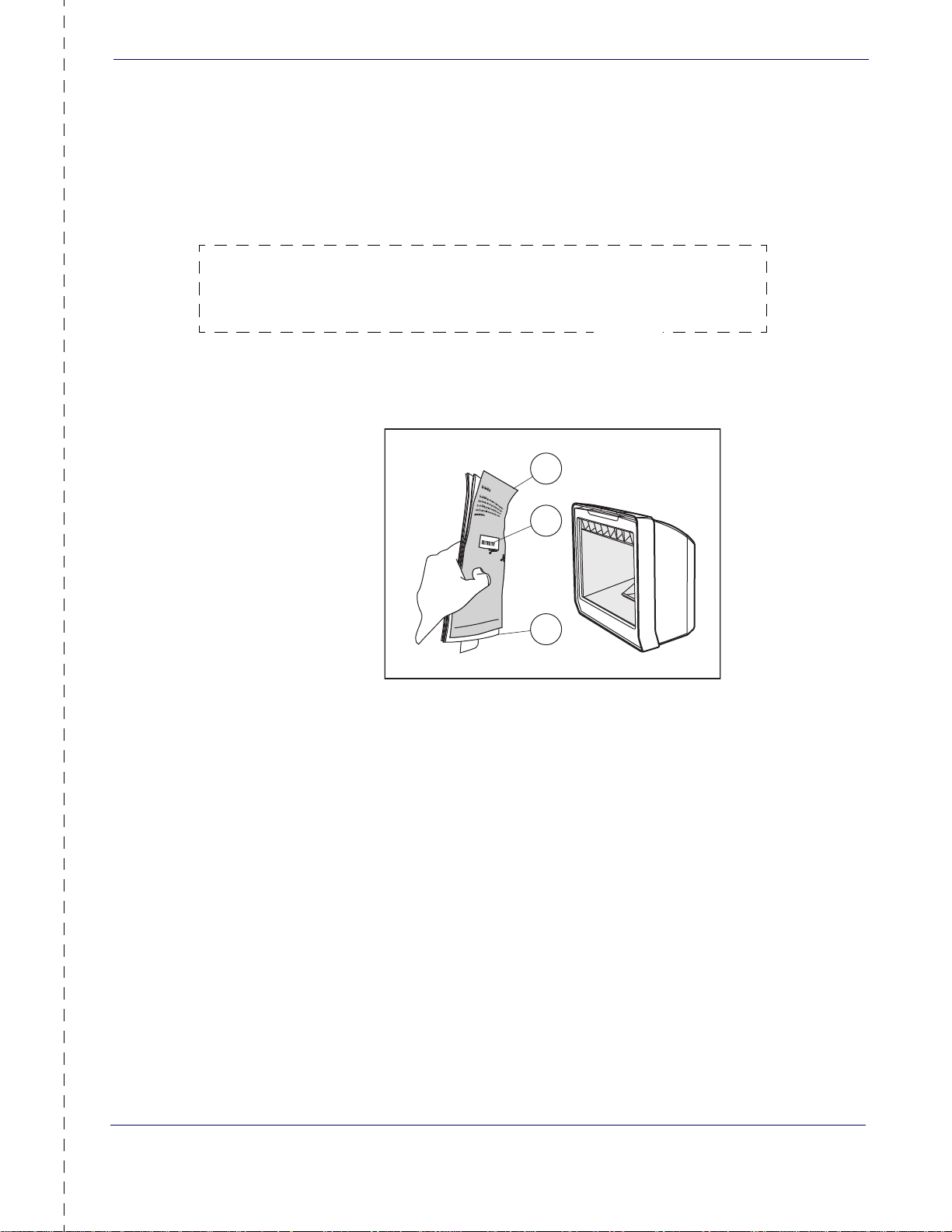
Bar Code Mask
1
2
3
Cut a hole in this page and remove it from the manual as indicated to create a sleeve through
which bar codes (starting in the following section) can be individually viewed and scanned. It is
important that only one bar code at a time be presented to the scanner.
Bar Code Mask
1. Bar Code Mask Sheet 3. Manual (folded)
2. Bar Code
Product Reference Guide
9
Page 19

Getting Started
Going Green
LED Class
Thank you for using the bar code mask on the opposite side of this page. This manual has been
formatted to minimize the quantity of pages needed to provide all of the programming bar
codes available for this product.
CLASS 1 LED PRODUCT APPARECCHIO LED CLASSE 1
LED KLASSE 1 APPAREIL A LED DE CLASSE 1
IEC / EN 60825-1:2007
Max output of LED radiation: 3.21mW per pulse at 100mm
Pulse duration: 200μs
Emitted wavelength 625nm
10
MagellanTM 3200VSi
Page 20
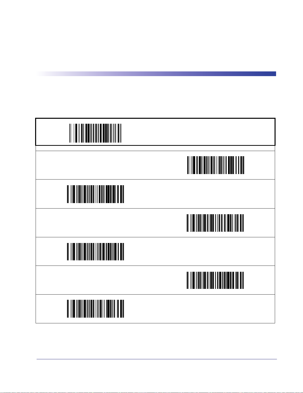
Double Read Timeout for Linear Labels
This Double Read Timeout feature sets a time limit that determines how much time must pass
before reading the same linear label again (e.g. two identical items in succession).
PROGRAMMING bar codes
0.1 Second
Chapter 2
General Features
START / END
0.3 Second
0.5 Second
0.2 Second
0.4 Second
DEFAULT
0.6 Second
Product Reference Guide
11
Page 21
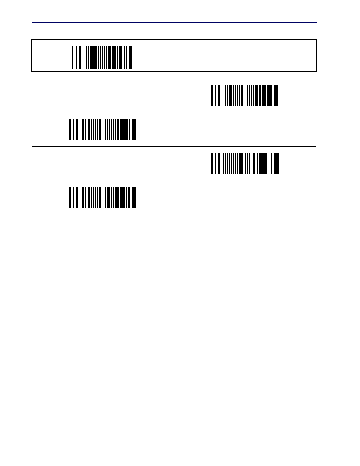
General Features
Double Read Timeout for Linear Labels — cont.
PROGRAMMING bar code
0.7 Second
0.9 Second
START / END
0.8 Second
1 Second
12
MagellanTM 3200VSi
Page 22
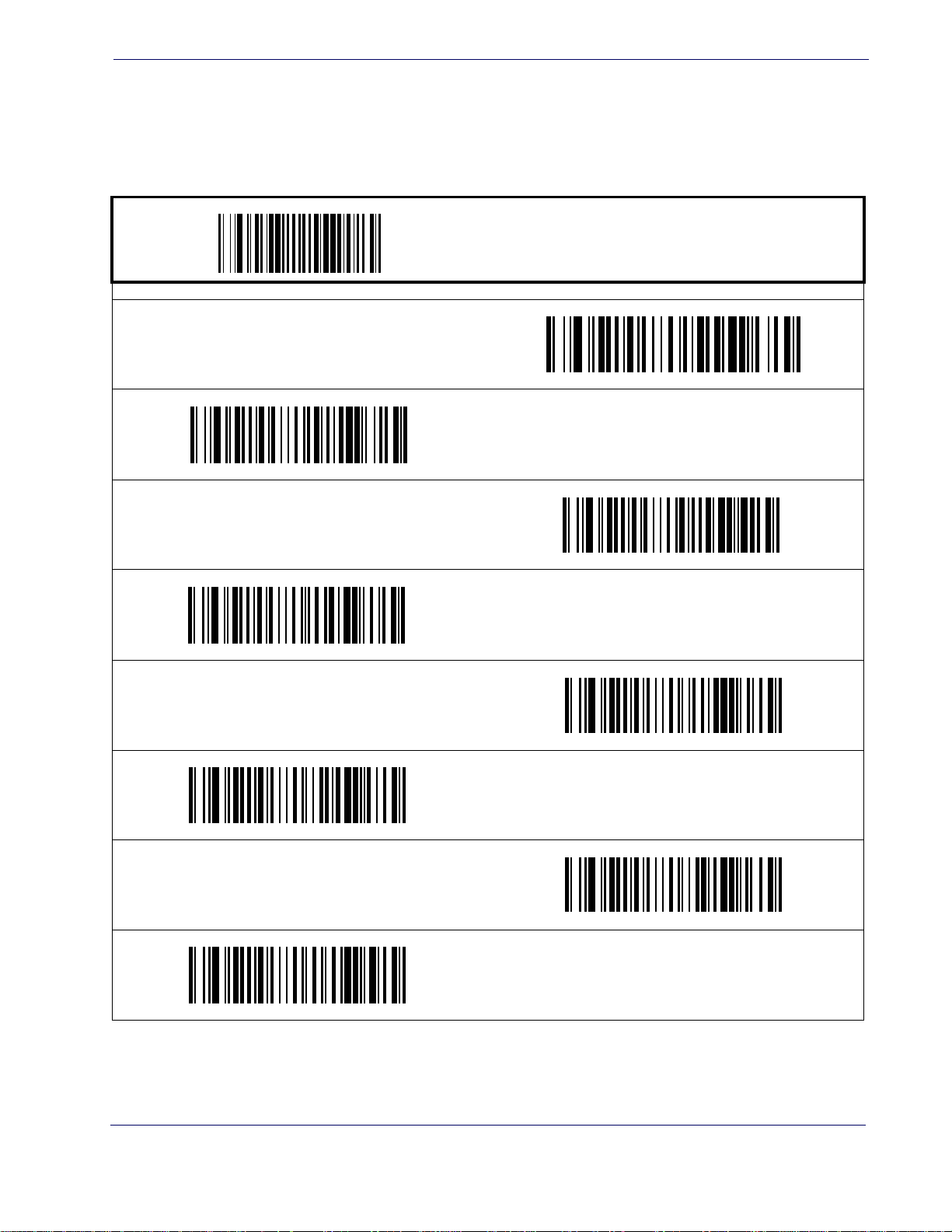
Double Read Timeout for 2D Labels
This Double Read Timeout feature specifies the minimum allowable time between consecutive
good reads of the same PDF 417, Micro PDF 417 Data Matrix, QR Code, Maxicode, Aztec or
Composite label.
PROGRAMMING bar codes
0.7 Second
DEFAULT
Double Read Timeout for 2D Labels
START / END
1 Second
1.5 Seconds
1.8 Seconds
2 Seconds
1.65 Seconds
1.95 Seconds
2.55 Seconds
Product Reference Guide
13
Page 23
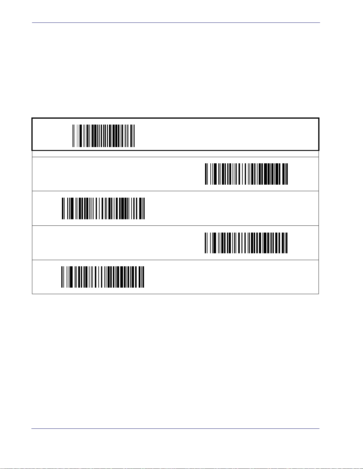
General Features
Scanner Button Options
This feature allows the user to configure the scanner (volume) button to different modes of
operation.
Options are:
• All functions (volume, tone, diagnostics, and reset)
• Enable only volume, tone, and reset
•Enable reset only
• Disable all button functions
Scanner Button Options = All functions
START / END
PROGRAMMING bar codes
Scanner Button Options = Enable reset only
Scanner Button Options =
Enable only volume, tone, and reset
DEFAULT
Scanner Button Options = Disable all button functions
14
MagellanTM 3200VSi
Page 24
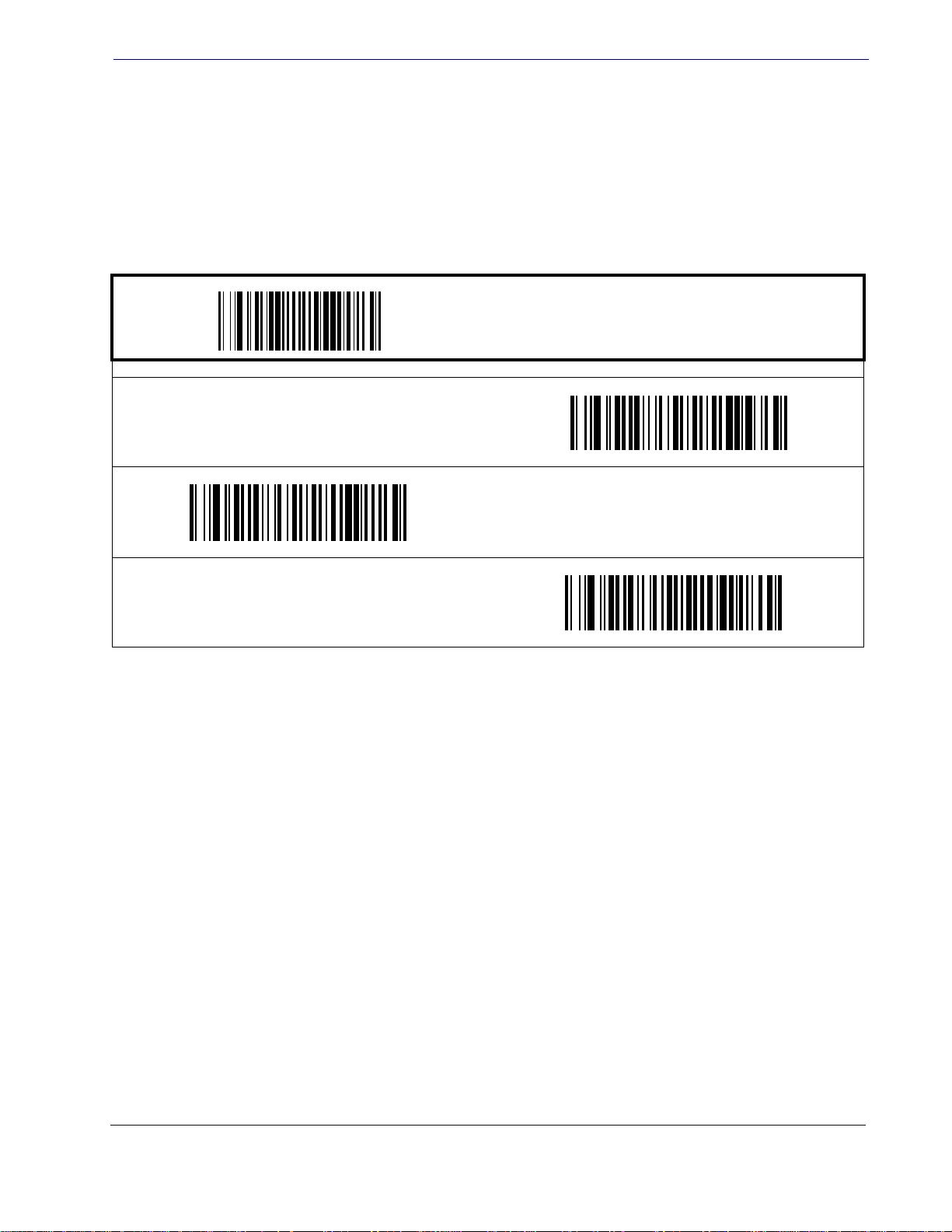
Camera Button Mode
Controls the function associated with the "Picture Taking" button
Options are:
• Normal Take Picture operation
• Activates Cell Phone Toggle Mode when not taking picture
• Activates Cell Phone One-Shot Mode when not taking pictures
PROGRAMMING bar codes
Camera Button Mode = Normal Take Picture opera-
tion
DEFAULT
Camera Button Mode
START / END
Camera Button Mode =
Activates Cell Phone One-Shot Mode when not taking pic-
tures
Camera Button Mode =
Activates Cell Phone Toggle Mode when not taking picture
Product Reference Guide
15
Page 25
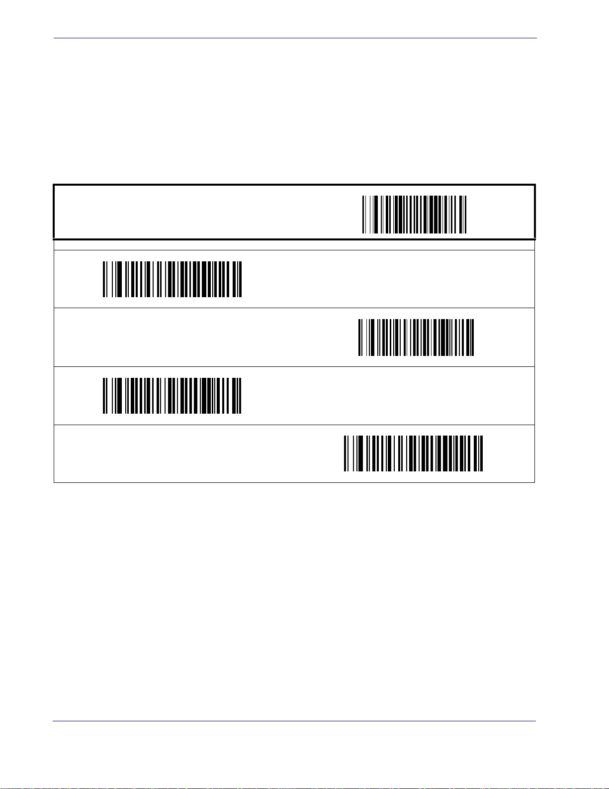
General Features
Auto Cell Phone Mode
Auto Cell Phone Mode enables the scanner to read bar codes on a cell phone display without
user intervention. For high ambient light conditions, button cell phone mode is recommended.
(See “Camera Button Mode” on page 15.)
Auto Cell Phone Mode Enable
Enables/disables Auto Cell Phone Mode.
START / END
PROGRAMMING bar codes
Auto Cell Phone Mode = Disable
DEFAULT
Auto Cell Phone Mode = Enable Normal
Auto Cell Phone Mode = Enable Sensitive Ambient
Auto Cell Phone Mode = Enable Sensitive
16
MagellanTM 3200VSi
Page 26
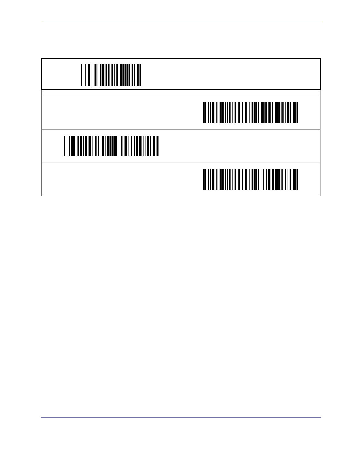
LED Level
LED Level
This feature defines the LED intensity level by pulse width.
START / END
PROGRAMMING bar codes
LED Level = Medium
LED Level = Low
LED Level = High
DEFAULT
Product Reference Guide
17
Page 27
General Features
Auxiliary Port Mode
Specifies the function associated with the auxillary interface.
Choices are:
•Disabled
• 01=Serial Handheld Enabled
• 02=PIR/CT Output plus Diagnostics Reporting
Disable Auxiliary Port Mode
DEFAULT
START / END
PROGRAMMING bar codes
Auxiliary Port Mode = PIR/CT Output plus Diagnostics
Reporting
Auxiliary Port Mode = Serial Handheld Enabled
18
MagellanTM 3200VSi
Page 28
Auxiliary Port Baud Rate
Specifies baud rate of auxillary port when operating in PIR/CT mode.
Auxiliary Port Baud Rate = 1200
Auxiliary Port Baud Rate = 4800
Auxiliary Port Baud Rate
START / END
PROGRAMMING bar codes
Auxiliary Port Baud Rate = 2400
Auxiliary Port Baud Rate = 19200
DEFAULT
Auxiliary Port Baud Rate = 57600
Auxiliary Port Baud Rate = 9600
Auxiliary Port Baud Rate = 38400
Auxiliary Port Baud Rate = 115200
Product Reference Guide
19
Page 29
General Features
Productivity Index Reporting (PIR)
When PIR is enabled, label quality data is appended to decoded data before being presented to
the POS. The PIR feature allows the scanner to provide information to an external computer,
indicating how easy the label was to read.
This value-added feature is a factory-programmed option. Contact your dealer for
informatio
NOTE
Disable
DEFAULT
to include this advanced capability.
PROGRAMMING bar codes
n about upgrading your system
START / END
Enable
20
MagellanTM 3200VSi
Page 30
Sleep Mode
Sleep Mode
This feature specifies the amount of time with no bar code reads before the scanner enters sleep
mode.
START / END
PROGRAMMING bar codes
Disable Sleep Mode
15 Seconds
1 Minute
3 Minutes
5 Minutes
DEFAULT
30 Seconds
2 Minutes
4 Minutes
Product Reference Guide
21
Page 31
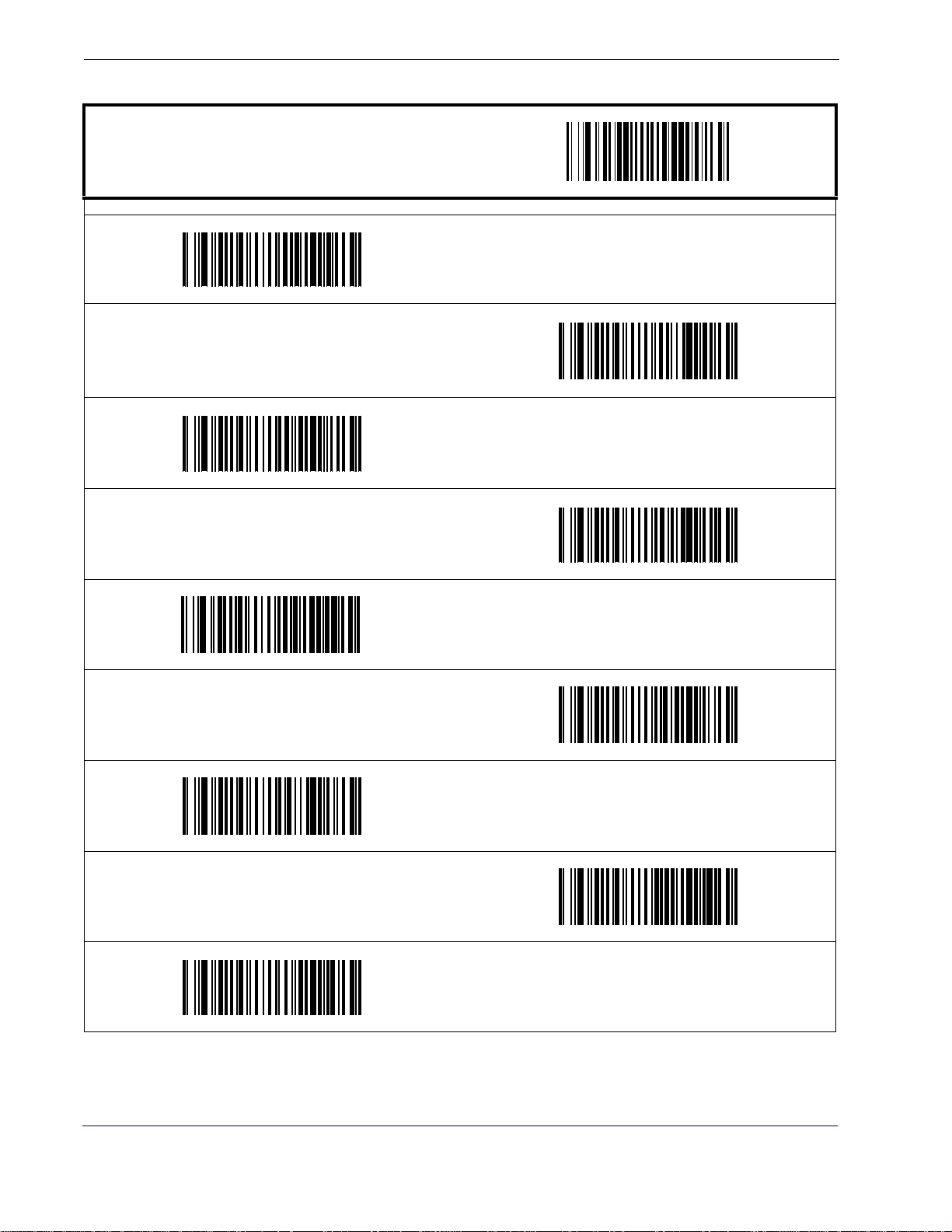
General Features
Sleep Mode — cont.
START / END
7 Minutes
PROGRAMMING bar codes
6 Minutes
8 Minutes
9 Minutes
12 Minutes
30 Minutes
10 Minutes
DEFAULT
15 Minutes
22
1 Hour
MagellanTM 3200VSi
Page 32
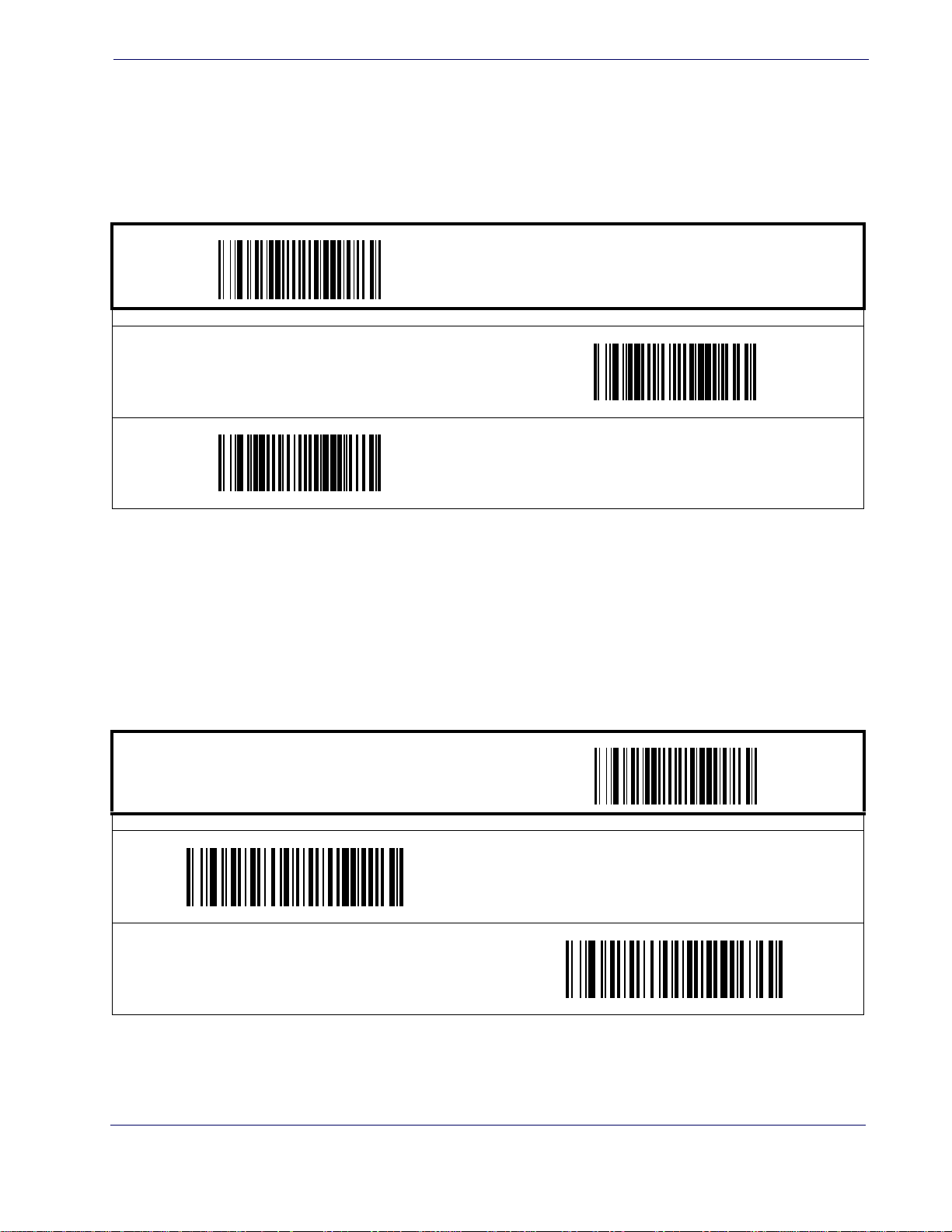
LED and Beeper Indicators
Power On Alert
Disables or enables the indication (a single beep) that the scanner has finished all its power up
tests and is now ready for operation.
Disable
LED and Beeper Indicators
START / END
PROGRAMMING bar codes
Enable
DEFAULT
External Read Indicator (ERI) Active State High
This feature is available only through
use of a special cable.
NOTE
START / END
PROGRAMMING bar codes
ERI Active State = Low
DEFAULT
ERI Active State = High
Product Reference Guide
23
Page 33
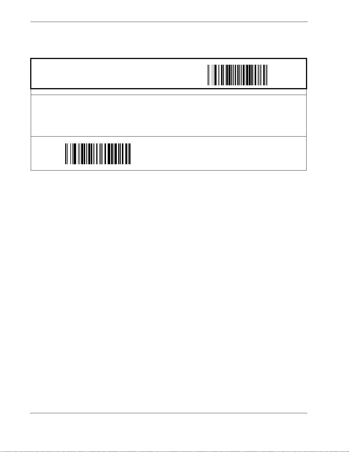
General Features
ERI Timeout
Specifies the amount of time the External Read Indicator (ERI) signal is held active for a good
read.
START / END
PROGRAMMING bar codes
Sets the ERI timeout duration using hex values from 000 to 255 in increments of ten milliseconds (10ms or
0.01 seconds). To configure this feature, scan the “STAR T/END” bar code above to place the unit in Programming Mode, then the “Set ERI T imeout,” followed by the two d
table in
Appendix C, Alpha-Numeric Pad representing the desired time value. Exit programming mode by scan-
ning the “START/END” bar code again.
DEFAULT SETTING FOR THIS FEATURE: 20 millis
igits (zero padded) from the Alphanumer ic
econds (02)
Set ERI Timeout
24
MagellanTM 3200VSi
Page 34
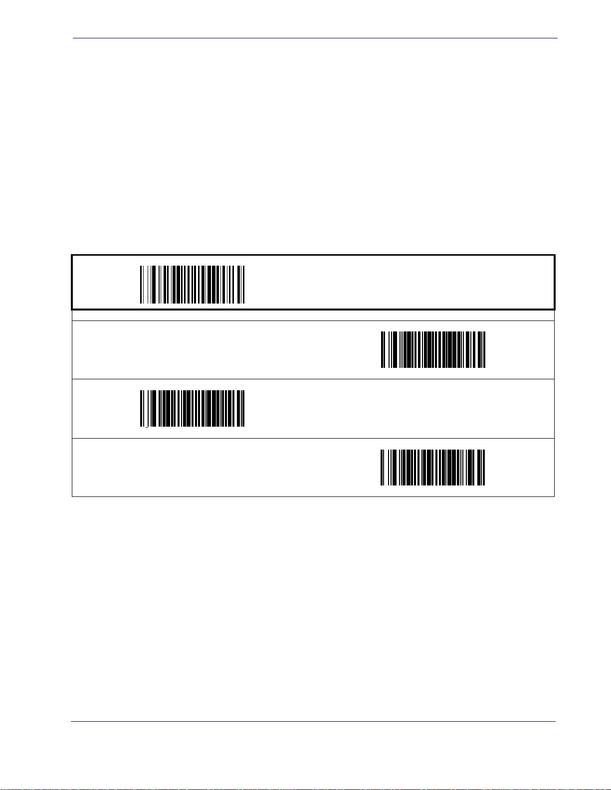
Good Read: When to Indicate
This feature specifies when the scanner will provide indication (beep and/or flash its green LED)
upon successfully reading a bar code. Choices are:
• Good Read = Indicate after decode
• Good Read = Indicate after transmit
LED and Beeper Indicators
• Good Read = Indicate after CTS goes inactive, then activ
This option (Indicate after CTS goes inactive,
then act
RS-232 interfaces.
NOTE
After Decode
DEFAULT
ive), which uses CTS, is only valid for
START / END
PROGRAMMING bar codes
After Transmit
e
After CTS goes inactive, then active
Product Reference Guide
25
Page 35
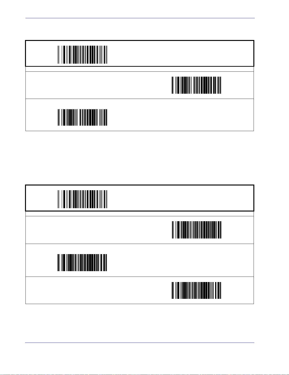
General Features
Good Read Beep Control
This feature enables/disables the scanner’s ability to beep upon a successful decode of a bar code.
Disable
START / END
PROGRAMMING bar codes
Enable
DEFAULT
Good Read Beep Frequency
Adjusts the good read beep to sound at a selectable low, medium or high frequency, selectable
from the list below. (Controls the beeper’s pitch/tone.)
Low
High
START / END
PROGRAMMING bar codes
Medium
DEFAULT
26
MagellanTM 3200VSi
Page 36
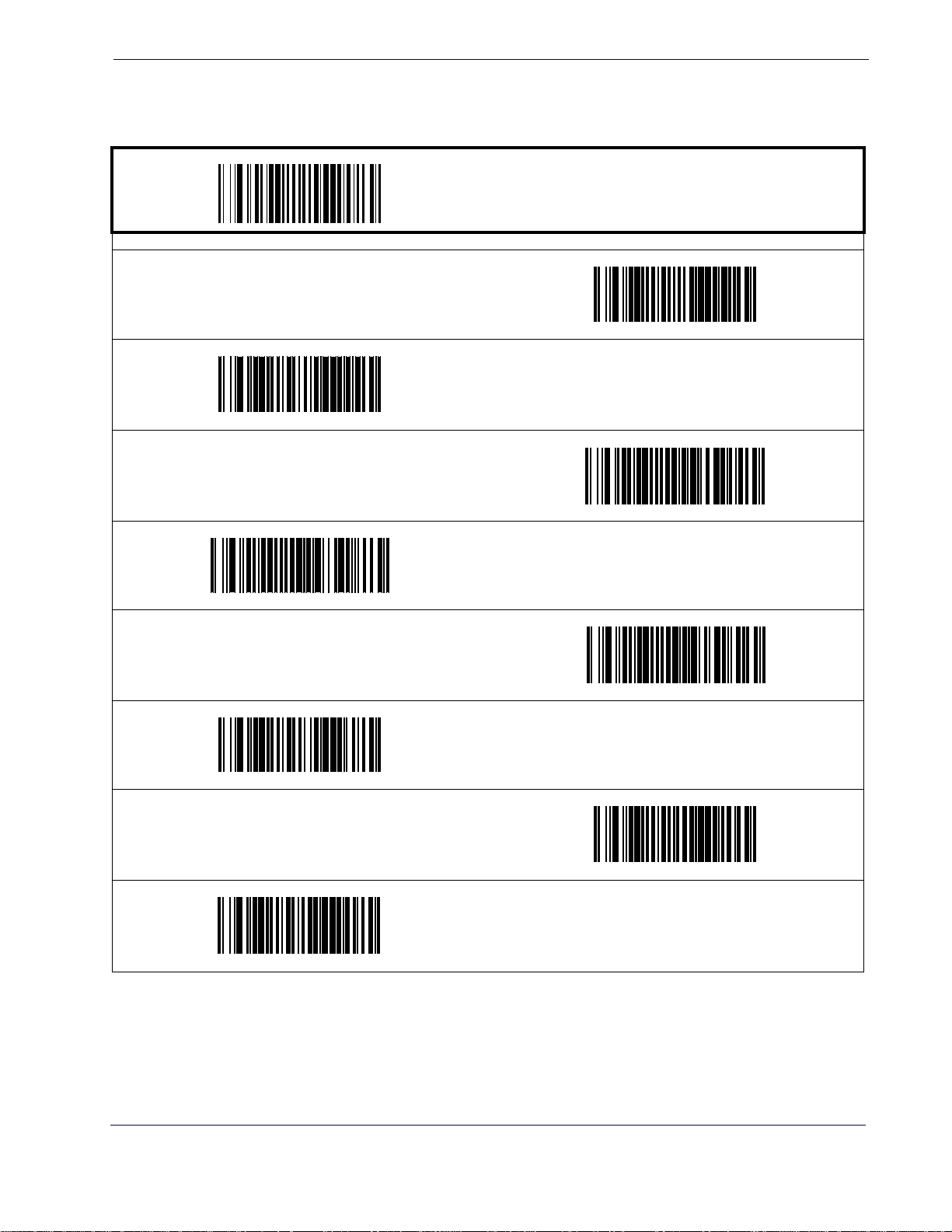
Good Read Beep Length
Specifies the duration of a good read beep.
60msec
100msec
LED and Beeper Indicators
START / END
PROGRAMMING bar codes
80msec
DEFAULT
140msec
180msec
120msec
160msec
200msec
Product Reference Guide
27
Page 37
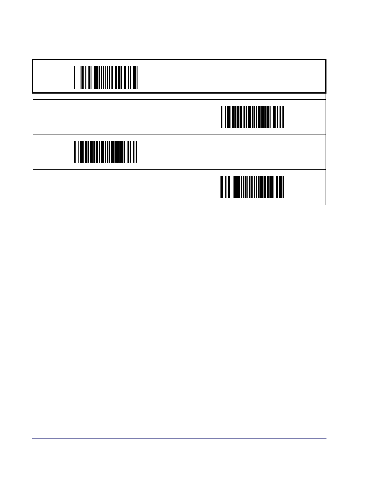
General Features
Good Read Beep Volume
Selects the beeper volume (loudness) upon a good read beep. There are three selectable volume
levels.
Low
High
DEFAULT
START / END
PROGRAMMING bar codes
Medium
28
MagellanTM 3200VSi
Page 38
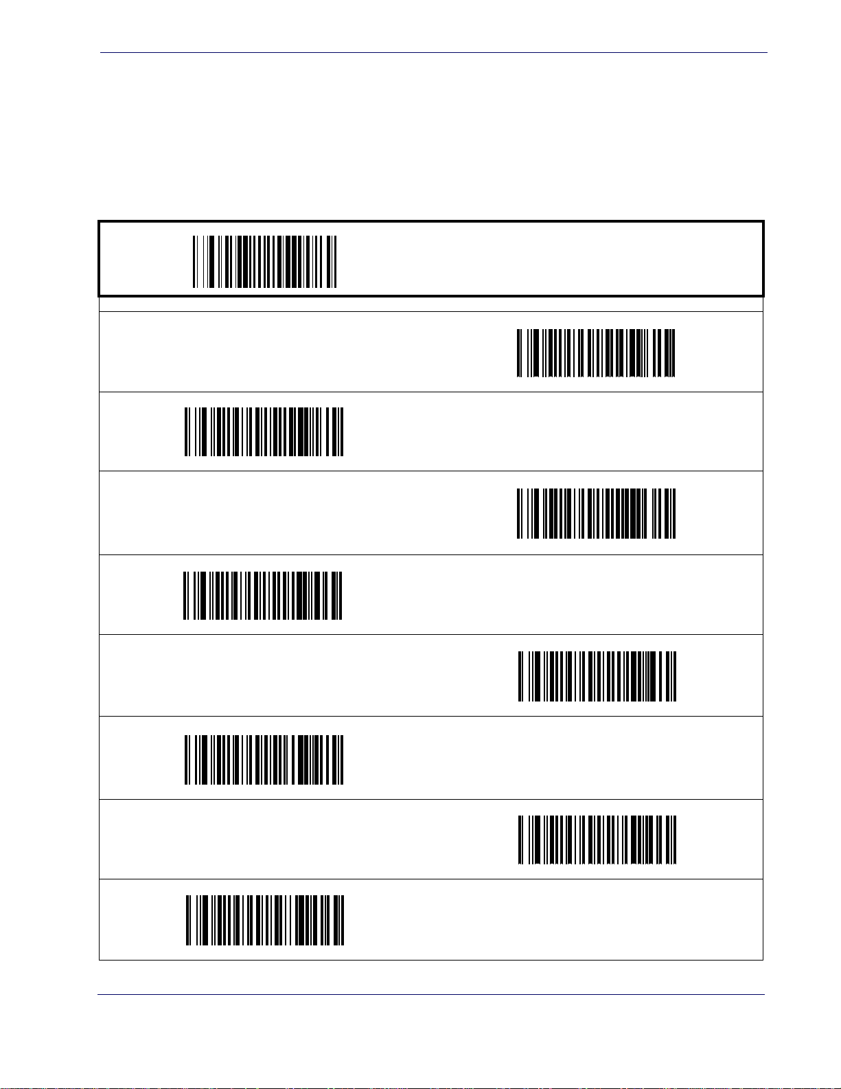
Scanning Features
Wake Up Intensity
This feature indicates the percentage of ambient light change which will trigger the scanner to
wake up from Sleep Mode. Lower settings provide greater sensitivity. The selectable range for
this setting is 5% to 15%.
Scanning Features
START / END
PROGRAMMING bar codes
5%
6%
7%
9%
11%
8%
10%
DEFAULT
12%
Product Reference Guide
29
Page 39
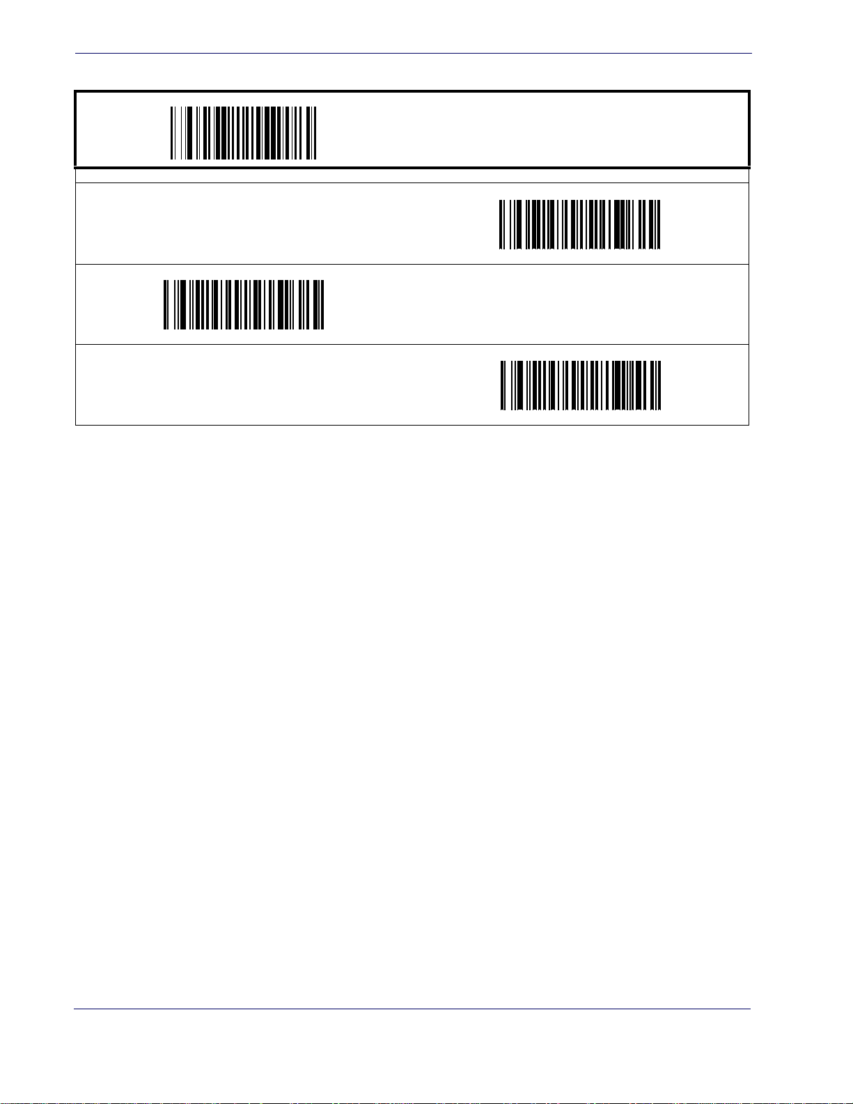
General Features
Wake Up Intensity — cont.
13%
15%
START / END
PROGRAMMING bar codes
14%
30
MagellanTM 3200VSi
Page 40

Image Capture
How to Capture an Image
There are two methods of capturing images as discussed below:
•
Image Capture to a microSD Card by Scanning a Special Label
• Image Capture to the Host by Host Command
Image Capture to a microSD Card by Scanning a Special Label
Insert a microSD card into the scanner, scan a capture label and place the item to be captured in
front of the scanner. Press and release the Camera Button. The image will be written to the
microSD card five seconds after button release.
The format, size, contrast, brightness and compression use the configured values.
Chapter 3
Image Capture
This Capture label is as follows:
<FNC3>IMAGEFAUTO<CR>
The Capture label will not read unless a microSD card is inserted.
NOTE
The image filename is automatically increased from image000 to image999.
The date image file generated is not actual, since no real time clock is emb
edded in the scanner.
Product Reference Guide
31
Page 41

Image Capture
Image Capture to the Host by Host Command
This feature is only available for RS-232 and USB COM interfaces.
If the USB COM interface has been selected, follow the USB COM Inter-
face Set-up instructions in the Interface Related Features chapter of this
guide.
NOTE
The host command format is as follows:
P<cnt>pSBC
where:
P - ASCII 'P' used as preamble of pass-through commands
<cnt> - binary value of 4 indicating 4 bytes to follow
p - ASCII lowercase 'p' ; command to take a picture
S - size value of image as ASCII character
‘S’ == uses scanner's configuration value
‘0’-VGA, (640X480)
‘1’-WVGA, (752X480)
‘2’-SXGA, (1280x1027)
‘3’-CIF (320x240)
B - brightness value in ASCII
‘B’ == uses scanner's configuration value CI_IMAGE_BRIGHTNESS
else ‘0’ thru’9’ specifies brightness
C - contrast value in ASCII
‘C’ == uses scanner configuration value CI_IMAGE_C
ONTRAST
else ‘0’ thru’9’ specifies contrast
IF the image is of a type the scanner supports, capture and transmission oc
curs, and the com-
mand is of proper format
THEN
The scanner will transmit an ACK (0x06) to the H
The
image data transmission starts with a 4 byte binary field representing (Big Endian)
ost in response to this command.
number of bytes to follow.
If the “number of bytes to follow” value is zero, there was a problem with generating the
image and the request should be retried.
ELSE
The scanner will transmit a BEL (0x07) to the Host in response to this command.
ENDIF
32
MagellanTM 3200VSi
Page 42
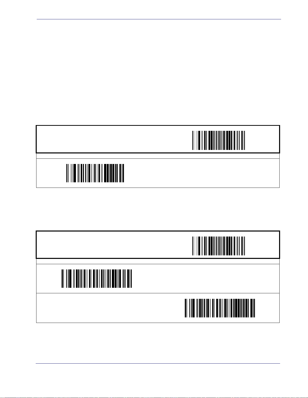
Image Compression
Specifies the starting image compression factor for JPEG images. A higher number specifies a
higher quality image with less compression than a relative lower number for the same image.
A value of 100 means minimal compression. A value of 1 means maximum compression at a loss
of quality. Fo
1. Scan the START bar code.
2. Scan the Set Image Compression bar code.
Image Compression
llow these steps to program this feature:
Image Format
Specifies the format of the captured image
3. Turn to
Alpha-Numeric Pad and scan the two digits (zero-padded) representing the desired
compression. The configurable range is 01-0x64 by increments of 01.
4. Scan the END bar code.
ST ART / END
PROGRAMMING bar codes
Set Image Compression
DEFAULT SETTING IS
100 (minimal compression — higher quality)
ST ART / END
PROGRAMMING bar codes
Image Format = JPG
DEFAULT
Image Format = BMP
Product Reference Guide
33
Page 43
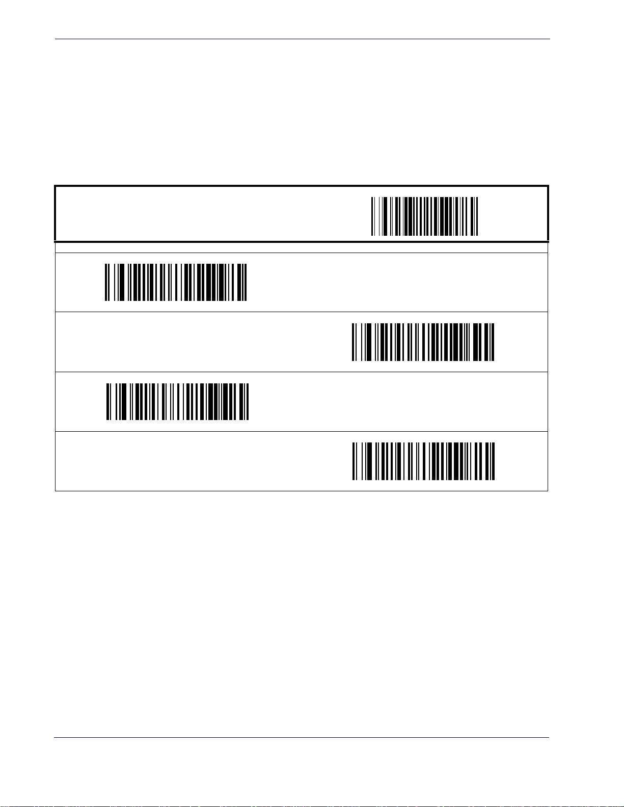
Image Capture
Image Size
Specifies the size of the image capture. Choices are:
•VGA
•WVGA
•SXGA, Full Size
•CIF
START / END
PROGRAMMING bar codes
Image Size = VGA
DEFAULT
Image Size = WVGA
Image Size = CIF
Image Size = SXGA, Full Size
34
MagellanTM 3200VSi
Page 44
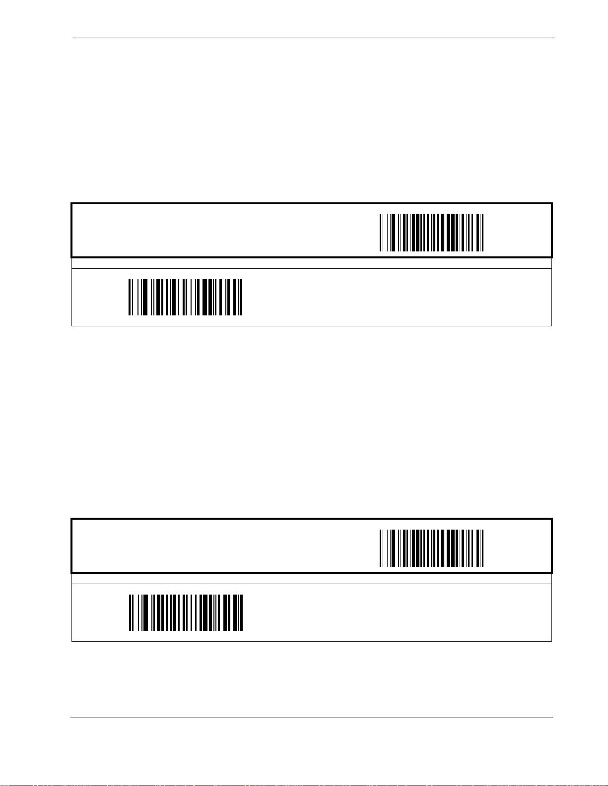
Image Brightness
This feature sets the image brightness value. Follow these instructions to configure this feature:
1. Scan the START bar code.
2. Scan the Set Image Brightness bar code.
Image Brightness
3. Turn to
4. Scan the END bar code.
Image Contrast
This feature sets the image contrast value. Follow these instructions to configure this feature:
1. Scan the START bar code.
Alpha-Numeric Pad and scan the two digits (zero-padded) representing the desired
brightness in decimal notation. The configurable range is 01-0x0A by increments of 01.
ST ART / END
PROGRAMMING bar codes
Set Image Brightness
DEFAULT SETTING FOR THIS FEATURE: 09
2. Scan the Set Image Contrast bar code.
3. Turn to
Alpha-Numeric Pad and scan the two digits (zero-padded) representing the desired
contrast in decimal notation. The configurable range is 01-0x0A by increments of 01.
Scan the END bar code.
4.
ST ART / END
PROGRAMMING bar codes
Set Image Contrast
DEFAULT SETTING FOR THIS FEATURE: 09
Product Reference Guide
35
Page 45

Image Capture
NOTES
36
MagellanTM 3200VSi
Page 46

Chapter 4
Interface Related Features
At the time of this writing, the reader supports the interfaces listed in Table 1. Select the desired
interface type from the table, then reference the page number give
section associated with each interface. See
Table 2 for a description of each Keyboard Wedge
interface type (A through Y as listed).
Tab l e 1. Interfaces Supported
RS-232 Page Keyboard Wedge 40
RS-232 Standard
RS-232 Wincor-Nixdorf
IBM 40
IBM 4683 Port 5B
IBM 4683 Port 9B
IBM 4683 Port 17
USB 40
USB-OEM
USB Keyboard
USB COM Interface
a. Consult Table 2 for more information regarding keyboard interface
types.
39 40
39 40
39 40
39 40
39 40
39 40
39 40
39 40
Keyboard Wedge A
Keyboard Wedge B
Keyboard Wedge C
Keyboard Wedge D
Keyboard Wedge E
Keyboard Wedge F
Keyboard Wedge G
Keyboard Wedge H
Keyboard Wedge I
Keyboard Wedge J
n for the customizable features
a
a
a
a
a
a
a
a
a
a
Product Reference Guide
NOTE
The correct interface cable is generally included
for the read
er interface type you ordered.
37
Page 47

Interface Related Features
Tab l e 2
. Keyboard Wedge Interface Reference
I/F Type PCs Supported
A PC/XT w/Alternate Key Encoding
AT, PS/2 25-286, 30-286, 50, 50Z, 60, 70, 80, 90 & 9
B
Key Encoding
C PS/2 25 and 30 w/Alternate Key Encoding
D PC/XT w/Standard Key Encoding
AT, PS/2 25-286, 30-286, 50, 50Z, 60, 70, 80, 90 & 95
E
Key Encoding
F PS/2 25 and 30 w/Standard Key Encoding
G IBM 3xxx w/122 keyboard
H IBM 3xxx w/102 keyboard
I PS/55 5530T w/104 keyboard
J NEC 9801
Reference Appendix E, Keyboard Function Key
Mappings for more information about keyboards.
NOTE
5 w/Alternate
w/Standard
38
MagellanTM 3200VSi
Page 48
Interface Selection
ST ART / END
RS-232 Wincor-Nixdorf
Interface Selection
PROGRAMMING bar codes
RS-232 Standard
IBM 4683 Port 5B
IBM 4683 Port 9B
USB-OEM
USB COM Interface
IBM 4683 Port 17
USB Keyboard
Product Reference Guide
39
Page 49
Interface Related Features
Interface Selection — cont.
START / END
Keyboard Wedge A
Keyboard Wedge C
PROGRAMMING bar codes
Keyboard Wedge B
Keyboard Wedge E
Keyboard Wedge G
Keyboard Wedge I
Keyboard Wedge D
Keyboard Wedge F
Keyboard Wedge H
40
Keyboard Wedge J
MagellanTM 3200VSi
Page 50
Interface Features
Obey/Ignore Host Commands
When set to ignore host commands, the scanner will ignore all host commands except for the
minimum set necessary to keep the interface active and transmit labels For normal operation of
the interface, select Obey Host Commands.
ST ART / END
Interface Features
PROGRAMMING bar codes
Obey Host Commands
DEFAULT
Ignore Host Commands
Product Reference Guide
41
Page 51
Interface Related Features
Interface Features — cont.
Host Transmission Buffers
Specifies the number of host transmission(s) that may be buffered. By buffering data from a bar
code, the scanner can continue to read a new bar code while the old one is being transmitted to
the host. Selecting BUFFERS = 1 means that the first bar code must be transmitted before a
new one can be read. A selection of BUFFERS = 2 means that a new bar code can be read while
data from the first bar code is transmitted.
When a DISABLE SCANNER command is received from the host, the scanner will continue to
transmit all da
START / END
ta that is buffered.
PROGRAMMING bar codes
Host Transmission Buffers = 2
DEFAULT
Host Transmission Buffers = 1
42
MagellanTM 3200VSi
Page 52
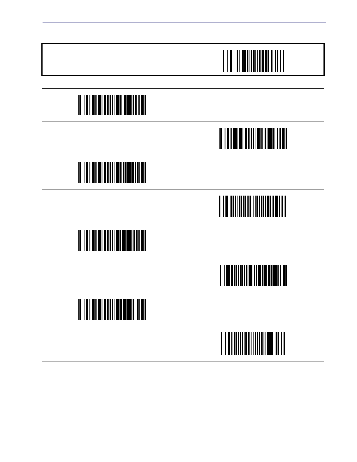
RS-232 Interface Features
ST ART / END
2400 Baud
Interface Features
PROGRAMMING bar codes
Baud Rate
1200 Baud
4800 Baud
9600 Baud
DEFAULT
38400 Baud
115200 Baud
19200 Baud
57600 Baud
Product Reference Guide
43
Page 53
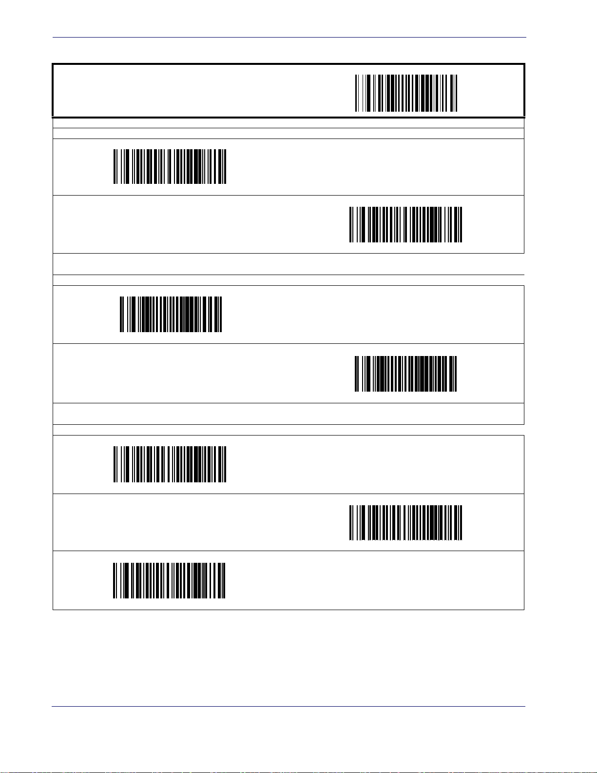
Interface Related Features
RS-232 Interface Features — cont.
START / END
PROGRAMMING bar codes
Data Bits
8 Data Bits
DEFAULT
Stop Bits
7 Data Bits
2 Stop Bits
Parity = Even
1 Stop Bit
DEFAULT
Parity
Parity = None
DEFAULT
Parity = Odd
44
MagellanTM 3200VSi
Page 54
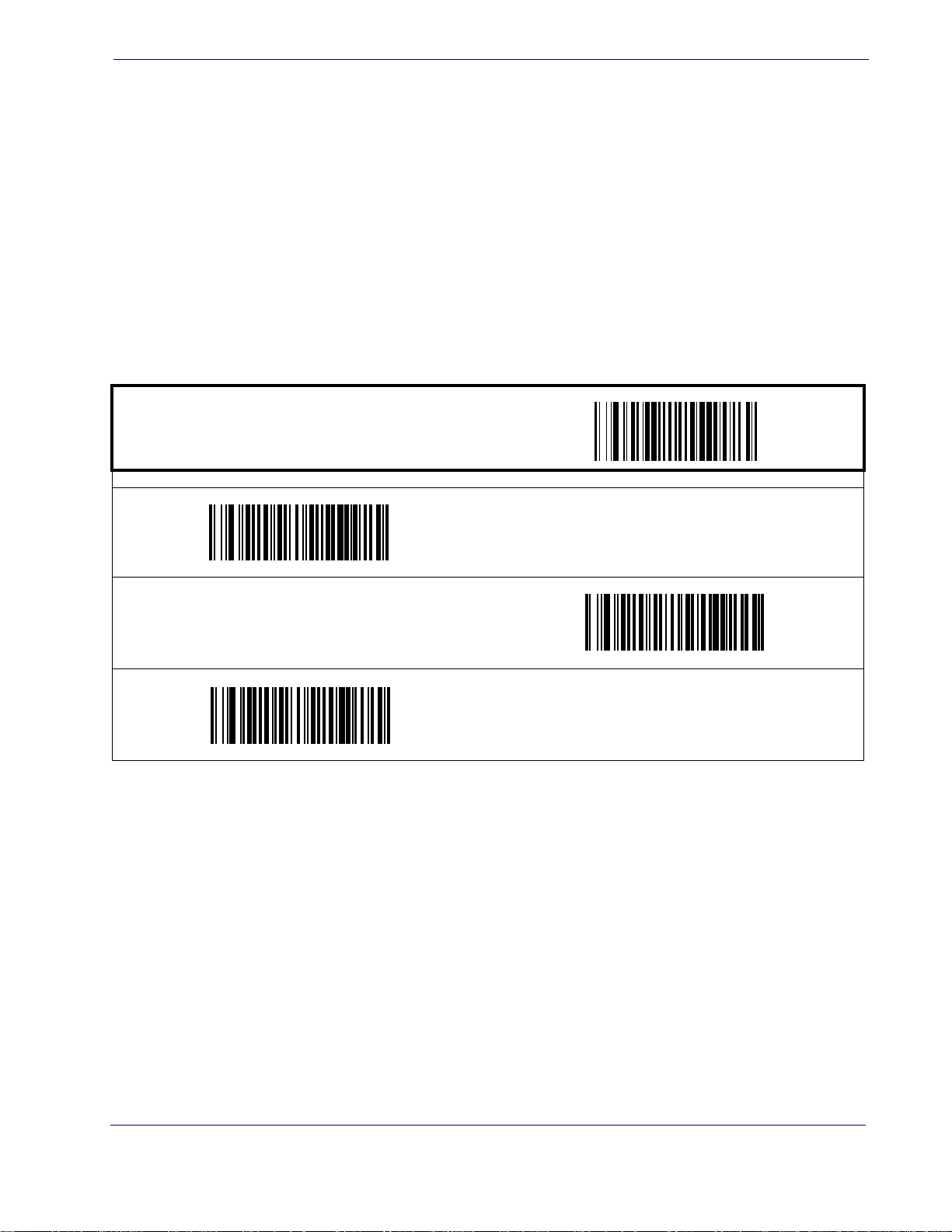
RS-232 Interface Features — cont.
Hardware Flow Control
Interface Features
Disable Hardware Control—
The scanner transmits to the host regardless of any activity on the
CTS line.
Enable CTS Flow Control—
Enable CTS Scan Control—
The CTS signal controls transmission of data to the host.
The CTS line must be active for the scanner to read and transmit data.
While the CTS line is inactive, the scanner remains in a host-disabled state; following a successful label transmission, the CTS signal must transition to inactive and then to active to enable
scanning for the next label.
ST ART / END
PROGRAMMING bar codes
Disable Hardware Control
DEFAULT
Enable CTS Flow Control
Enable CTS Scan Control
Product Reference Guide
45
Page 55
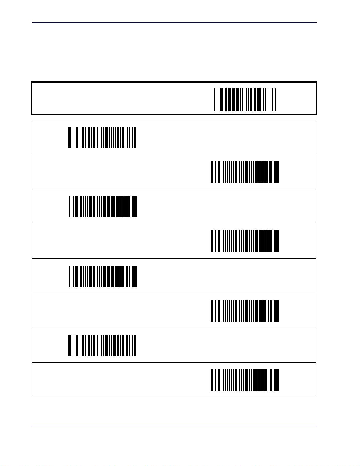
Interface Related Features
RS-232 Interface Features — cont.
Intercharacter Delay
This delay is inserted after each data character transmitted. If the transmission speed is too high,
the system may not be able to receive all characters. You may need to adjust the delay to make
the system work properly.
START / END
Interchar Delay = 10 msec
PROGRAMMING bar codes
Inter-Char Delay = No Delay
DEFAULT
Interchar Delay = 30 msec
Interchar Delay = 50 msec
Interchar Delay = 20 msec
Interchar Delay = 40 msec
Interchar Delay = 60 msec
46
Interchar Delay = 70 msec
MagellanTM 3200VSi
Page 56
Intercharacter Delay — cont.
ST ART / END
PROGRAMMING bar codes
Interchar Delay = 80 msec
Interchar Delay = 90 msec
Software Flow Control
Disables/Enables software control using XON/XOFF characters.
Interface Features
ST ART / END
Enable Software Flow Control
PROGRAMMING bar codes
Disable Software Flow Control
DEFAULT
Product Reference Guide
47
Page 57
Interface Related Features
RS-232 Interface Features — cont.
Host Echo
When enabled, this feature passes all data through the scanner to the host as it comes in. This
feature is used for applications where “daisy chaining” of RS-232 devices onto the same cable is
necessary. If, for example, one of the devices in the chain is a terminal where someone is entering
data while another person is simultaneously scanning a bar code requiring transmission to the
host, the scanner will wait for the RS-232 channel to be quiet for a specified period of time (set
RS-232 Host Echo Quiet Interval). The scanner can be set to observe this delay before sending its
via
data in order to avoid RS-232 transmission conflicts.
START / END
PROGRAMMING bar codes
Disable Host Echo
DEFAULT
Enable Host Echo
48
MagellanTM 3200VSi
Page 58
RS-232 Interface Features — cont.
Host Echo Quiet Interval
This setting specifies the time interval of RS-232 channel inactivity which must transpire before
the scanner will break the host echo loop to transmit the bar code data that has just been
scanned to the host.
ST ART / END
PROGRAMMING bar codes
Host Echo Quiet Interval = 10msec
DEFAULT
Interface Features
Host Echo Quiet Interval = 0msec
Host Echo Quiet Interval = 30msec
Host Echo Quiet Interval = 50msec
Host Echo Quiet Interval = 20msec
Host Echo Quiet Interval = 40msec
Host Echo Quiet Interval = 60msec
Host Echo Quiet Interval = 70msec
Product Reference Guide
49
Page 59
Interface Related Features
Host Echo Quiet Interval — cont.
Host Echo Quiet Interval = 90msec
START / END
PROGRAMMING bar codes
Host Echo Quiet Interval = 80msec
Host Echo Quiet Interval = 100msec
Signal Voltage: Normal/TTL
Specifies whether the RS-232 interface provides TTL levels on the output pins TxD and RTS.
START / END
PROGRAMMING bar codes
Signal Voltage: Normal RS-232
DEFAULT
Signal Voltage: TTL
50
MagellanTM 3200VSi
Page 60
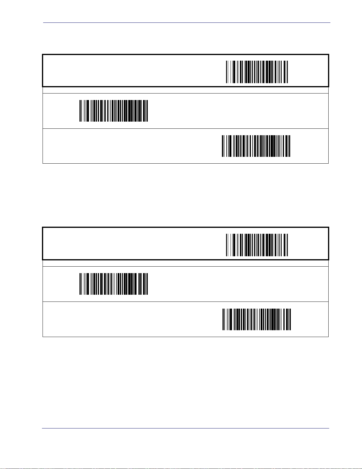
RS-232 Invert
Enables/disables inversion of RS-232 TXD and RXD signals.
ST ART / END
PROGRAMMING bar codes
Disable RS-232 Invert
Enable RS-232 Invert
Interface Features
DEFAULT
Beep on ASCII BEL
Enables/disables ability of scanner to beep (sound a good read tone) on receiving an ASCII BEL
(07 hex).
ST ART / END
PROGRAMMING bar codes
Enable Beep on ASCII BEL
DEFAULT
Disable Beep on ASCII BEL
Product Reference Guide
51
Page 61
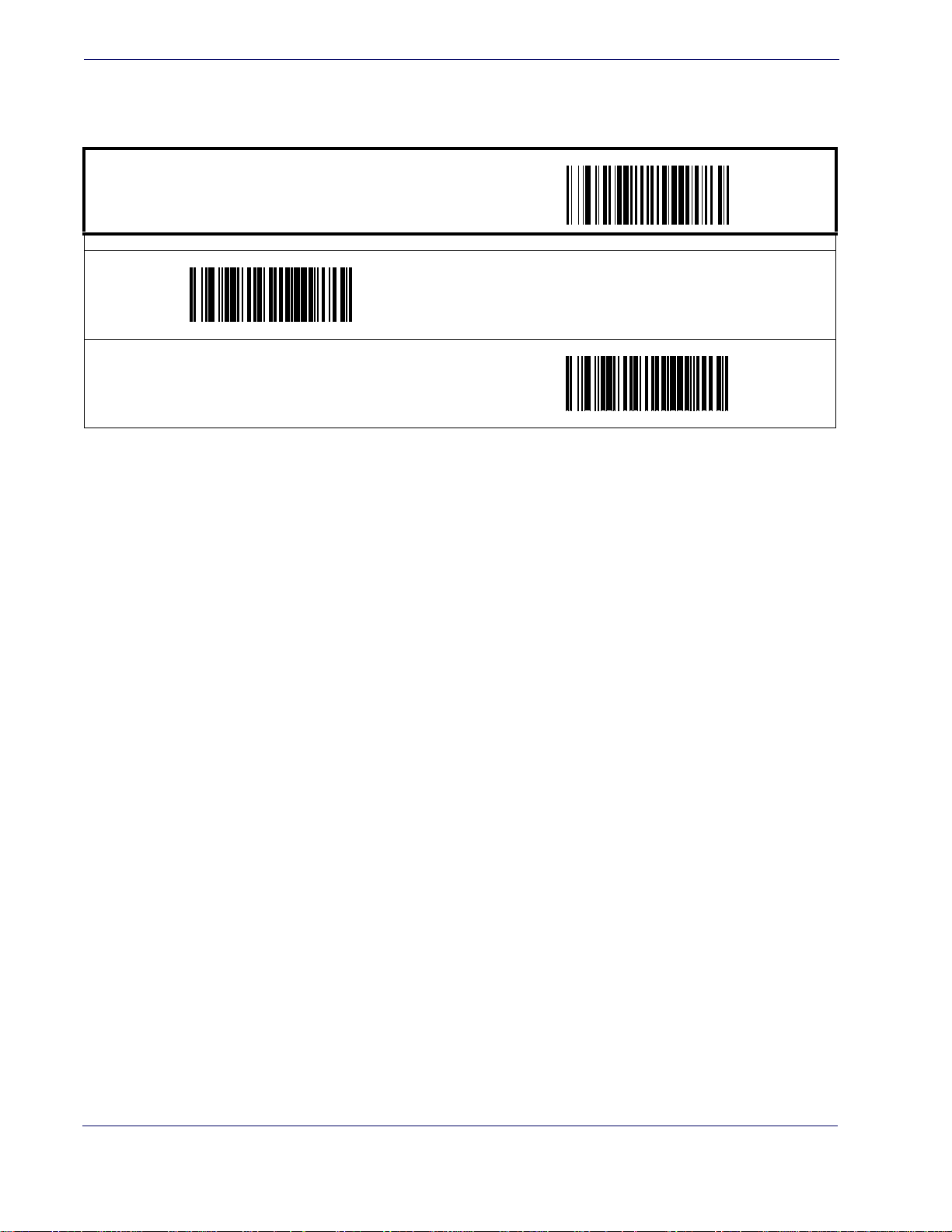
Interface Related Features
Beep on Not on File
Select for the host to beep (or not) when a not-on-file (host command) condition is detected by
the host.
Enable Beep on Not On File
START / END
PROGRAMMING bar codes
Disable Beep on Not On File
DEFAULT
52
MagellanTM 3200VSi
Page 62
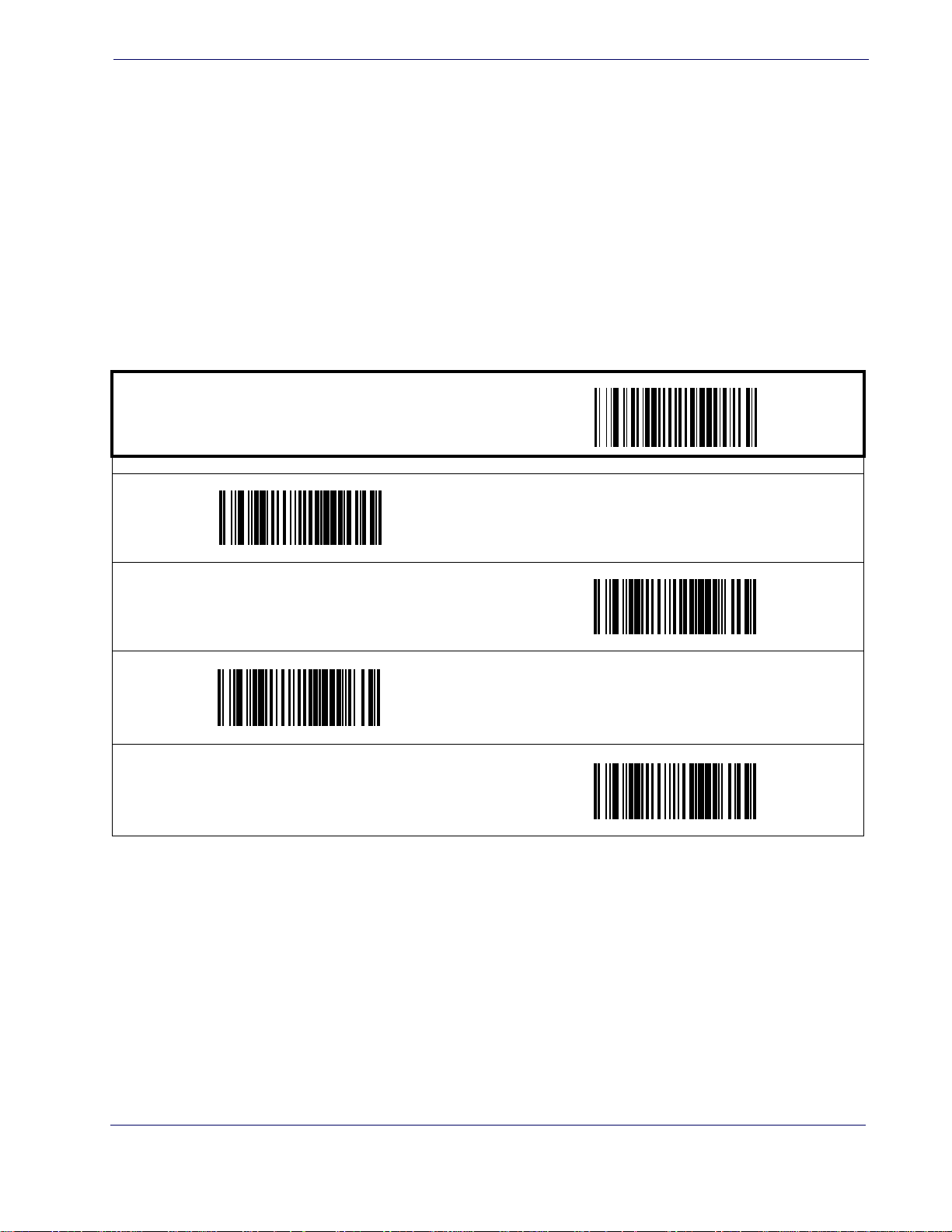
Interface Features
ACK NAK Options
This enables/disables the ability of the scanner to support the RS-232 ACK/NAK protocol.
When configured, the scanner and/or host sends an “ACK” when it receives data properly, and
sends “NAK” when the data is in error. Selections for this option are:
•Disable
• Enable for label transmission — the scanner expects an ACK/NAK response from the host
when a
label is sent
• Enable for host-command
when
the host send
• Enable for label transmission and host-command acknowledge
ST ART / END
Enable ACK NAK for Transmission
acknowledge — the scanner will respond with ACK/NAK
s a command
PROGRAMMING bar codes
Disable ACK NAK
DEFAULT
Enable ACK NAK for host command acknowledge
Enable ACK NAK for transmission and host command
Product Reference Guide
53
Page 63
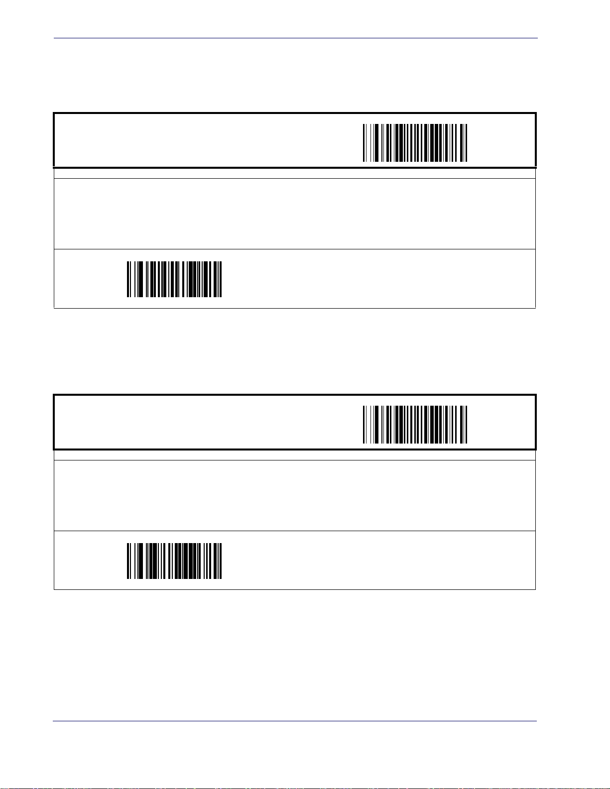
Interface Related Features
RS-232 Interface Features — cont.
ACK Character
START / END
PROGRAMMING bar codes
Sets the ACK character from the set of ASCII characters or any
three digits with zeros, as in “005”. To configure this feature, scan the “START/END” bar code above to place the unit in
Programming Mode, then the “Set ACK Character,” followed by the digits from the Alphanumeric table in Appendix C,
Alpha-Numeric Pad representing your desired character. Exit programming mo
code above.
DEFAULT SETTING FOR THIS FEATURE: 006
decimal value from 000 to 255. Pad entries of less than
de by again scanning the “START /END” bar
Set ACK Character
NAK Character
START / END
PROGRAMMING bar codes
Sets the NAK character from the set of ASCII characters or any decimal value from 000 to 255. Pad entries of less than
three digits with zeros, as in “005”. To configure this feature, scan the “START/END” bar code above to place the unit in
Programming Mode, then the “Set NAK Character,” followed by the digits from the Alphanumeric table in Appendix C,
Alpha-Numeric Pad representing your desired character. Exit programming mo
code above.
DEFAULT SETTING FOR THIS FEATURE: 021
de by again scanning the “START /END” bar
Set NAK Character
54
MagellanTM 3200VSi
Page 64
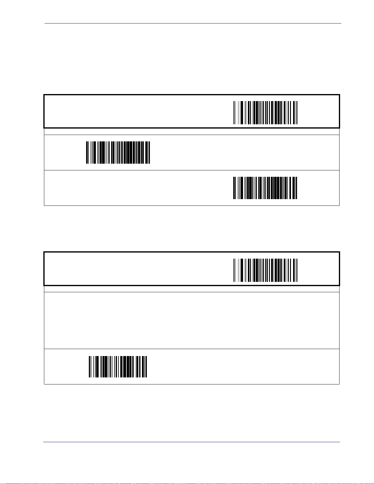
RS-232 Interface Features — cont.
Retry on ACK NAK Timeout
Enables/disables retry after the configurable ACK NAK Timeout Value (set in the following feature) has expired.
ST ART / END
PROGRAMMING bar codes
Enable Retry on ACK NAK Timeout
DEFAULT
Interface Features
Disable Retry on ACK NAK Timeout
ACK NAK Timeout Value
ST ART / END
PROGRAMMING bar codes
This item specifies the time the scanner will wait for an ACK character from the host following a label transmission.
00 = Infinite timeout
01 - 75 = Timeout in 200-millisecond increments
To configure this feature, scan the “START/END”
ACK NAK Timeout Value,” followed by the two digits (zero padded) from the Alphanumeric table in Appendix C, Alpha-
Numeric Pad
above.
representing your desired value. Exit programming mode by again scanning the “START/END” bar code
DEFAULT SETTING FOR THIS FEATURE: 01 (200 msec)
bar code above to place the unit in Programming Mode, then the “Set
Set ACK NAK Timeout Value
Product Reference Guide
55
Page 65
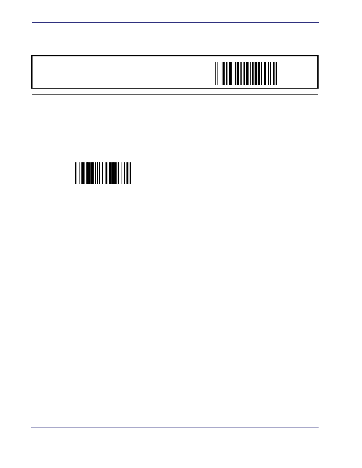
Interface Related Features
RS-232 Interface Features — cont.
ACK NAK Retry Count
START / END
PROGRAMMING bar codes
This feature sets the number of times for the scanner to retry a label transmission under a retry condition.
000 = No retry
001 - 254 = Retry for the specified number of times
255 = Retry forever
To configure this feature, scan the “START
ACK NAK Retry Count,” followed by the three digits (zero padded) from the Alphanumeric table in Appendix C, Alpha-
Numeric Pad representing your desired retry count. Exit programming mode by again scanning the “START/END” bar code
above
DEFAULT SETTING FOR THIS FEATURE: 003
/END” bar code above to place the unit in Programming Mode, then the “Set
Set ACK NAK Timeout Value
56
MagellanTM 3200VSi
Page 66
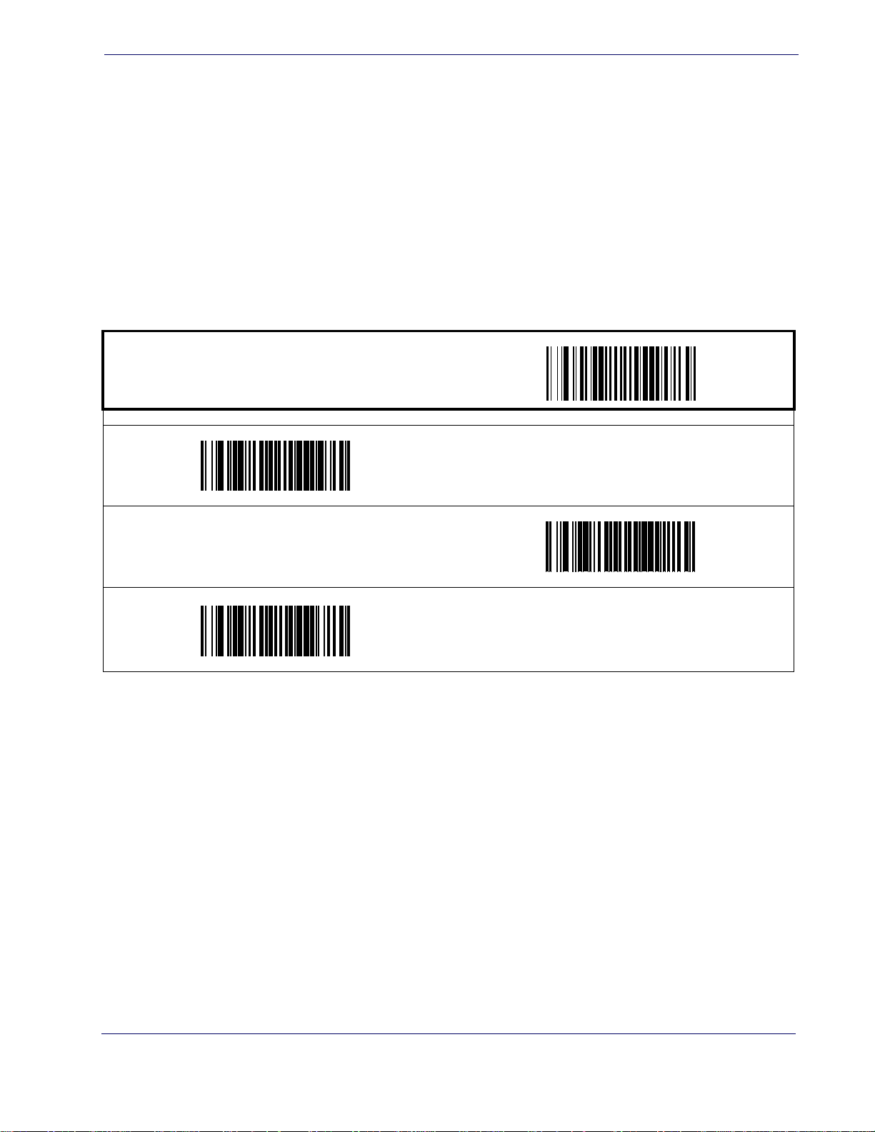
RS-232 Interface Features — cont.
ACK NAK Error Handling
This item specifies the method the scanner will use to handle errors detected while waiting to
receive the ACK character from the host. Errors include unrecognized host commands and communication errors such as parity or framing errors. Choices are:
00 = Ignore errors detected (recommended setting)
01 = Process error as valid ACK character (risk of lost label data)
02 = Process error as valid NAK character (risk of duplicate label data)
ST ART / END
PROGRAMMING bar codes
Interface Features
Process error as valid ACK character
Ignore Errors Detected
DEFAULT
Process error as valid NAK character
Product Reference Guide
57
Page 67
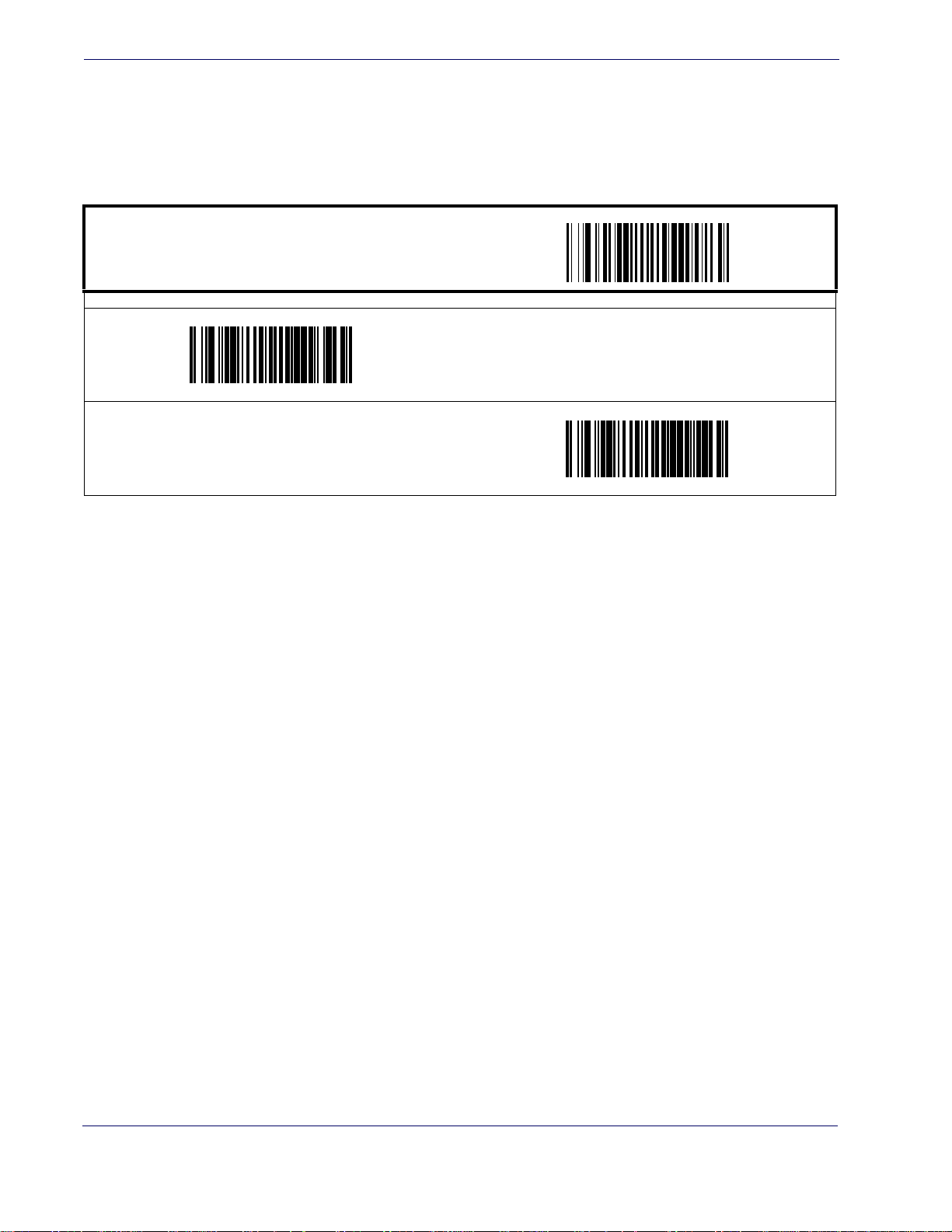
Interface Related Features
RS-232 Interface Features — cont.
Transmission Failure Indication
Enables/disables bad-label indication upon transmission failure.
START / END
PROGRAMMING bar codes
Enable Transmission Error Indication
DEFAULT
Disable Transmission Error Indication
Single Cable RS-232
Single Cable RS-232 Options
The RS-232 Single Cable interface shares some configuration options with other RS-232 interfaces. Rather than repeat them in this section as Single Cable options, please
enced as follows:
RS-232 Baud Rate on
RS-232 Number of Data Bits on page 44
RS-232 Number of Stop Bits on page 44
RS-232 Parity on page 44
RS-232 Software Flow Control on page 47
RS-232 Beep on Not on File on page 52
RS-232 Label ID Control on page 76
find them refer-
page 43
58
MagellanTM 3200VSi
Page 68
Single Cable RS-232 RTS CTS Selection
Specifies how RTS and CTS are used to control the data flow. RTS is controlled by the Scanner
and can be continuously held high/low, or can be asserted during label transmission. The scanner looks at CTS, as the configuration values state, to
Choices are:
• Option 0 = RTS is held in low state and CTS is ignored
• Option 1 = RTS is held in high state and CTS is ignored
• Option 2 = Assert RTS and wait for CTS to be asserted
• Option 3 = Assert RTS and ignore CTS
• Option 4 = RTS held low, wait for CTS to be asserted
• Option 5 = RTS held high, wait for CTS to be asserted
ST ART / END
Single Cable RS-232
determine when to send label data.
PROGRAMMING bar codes
RTS CTS Selection =
RTS is held in high state and CTS is ignored
RTS CTS Selection =
Assert RTS and ignore CTS
RTS CTS Selection =
RTS is held in low state and CTS is ignored
RTS CTS Selection =
Assert RTS and wait for CTS to be asserted
RTS CTS Selection =
RTS held low, wait for CTS to be asserted
RTS CTS Selection =
RTS held high, wait for CTS to be asserted
DEFAULT
Product Reference Guide
59
Page 69
Interface Related Features
Single Cable RS-232 Use BCC
Enables/disables the ability of the scanner to use BCC.
START / END
Enable BCC
DEFAULT
PROGRAMMING bar codes
Disable BCC
Single Cable RS-232 Use ACK/NAK
Enables/disables the ability of the scanner to use ACK/NAK.
START / END
Enable ACK/NAK
DEFAULT
PROGRAMMING bar codes
Disable ACK/NAK
60
MagellanTM 3200VSi
Page 70
Single Cable RS-232 Use STX
Enables/disables the ability of the scanner to use STX.
ST ART / END
Enable STX
DEFAULT
Single Cable RS-232
PROGRAMMING bar codes
Disable STX
Set Single Cable RS-232 STX Character
This feature selects the STX character.
To specify the STX Character:
1. Scan the START/END bar code.
2. Scan the bar code, SET SINGLE CABLE RS-232 STX CHARACTER below. You’ll need
to cover any unused bar cod
the bar code you intend to scan.
3. Scan the appropriate characters/digits from the keypad in
decimal designation for the desired character. A table containing the ASCII Character Set
and their correspondi
ASCII parameters must be input by scanning decimal digits for each character. Pad all
numbers with leading zeroes to yield a three-digit entry (001-127). Thus, to set a single
character value of A, bar codes containing the digits ‘0’, ‘6’ and ‘5’ must be scanned. The
selectable range for this option is any decimal value from 001 to 127.
4. The scanner will automatically exit Programming Mode when the appropriate amount of digits have been scanned.
ng hex values is available in the inside back cover of this manual.
es on this and the facing page to ensure the scanner reads only
Appendix C that represent the
SET SINGLE CABLE RS-232 STX CHARACTER
Product Reference Guide
61
Page 71
Interface Related Features
Single Cable RS-232 Use ETX
Enables/disables the ability of the scanner to use ETX.
START / END
Enable ETX
DEFAULT
PROGRAMMING bar codes
Disable ETX
Set Single Cable RS-232 ETX Character
Allows selection of the ETX character.
To specify the ETX Character:
1. Scan the START/END bar code.
2. Scan the bar code, SET SINGLE CABLE RS-232 ETX CHARACTER below. You’ll need
to cover any unused bar cod
the bar code you intend to scan.
3. Scan the appropriate characters/digits from the keypad in
decimal designation for the desired character. A table containing the ASCII Character Set
and their correspondin
ASCII parameters must be input by scanning decimal digits for each character. Pad all
numbers with leading zeroes to yield a three-digit entry (001-127). Thus, to set a single
character value of A, bar codes containing the digits ‘0’, ‘6’ and ‘5’ must be scanned. The
selectable range for this option is any decimal value from 001 to 127.
4. The scanner will automatically exit Programming Mode when the appropriate amount of digits have been scanned.
g decimal values is available in the inside back cover of this manual.
es on this and the facing page to ensure the scanner reads only
Appendix C that represent the
SET SINGLE CABLE RS-232 ETX CHARACTER
62
MagellanTM 3200VSi
Page 72
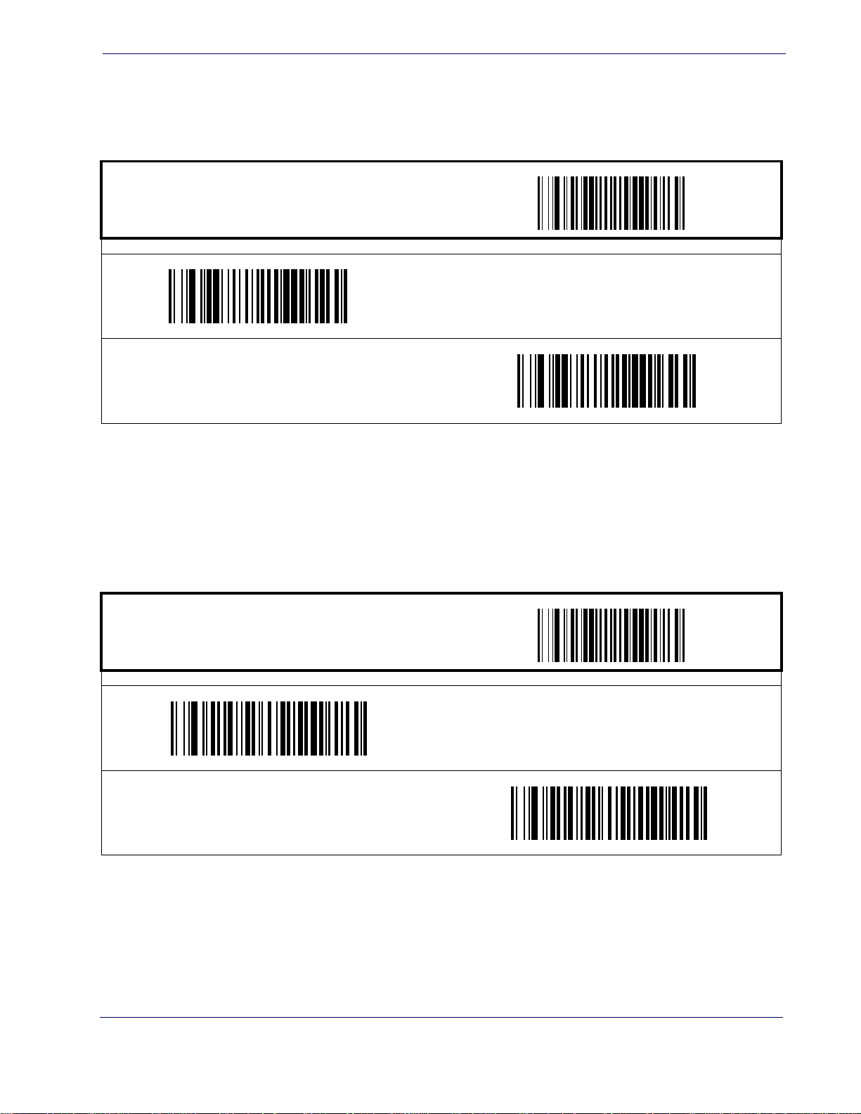
Single Cable Pacesetter Plus
Enables/disables sending Pacesetter Plus information as trailers to UPC/EAN labels.
ST ART / END
Enable Pacesetter Plus
Single Cable RS-232
PROGRAMMING bar codes
Disable Pacesetter Plus
DEFAULT
Single Cable Datalogic Extensions
Enables Datalogic extensions to the Single Cable RS-232 interface.
ST ART / END
Enable Datalogic Extensions
PROGRAMMING bar codes
Disable Datalogic Extensions
DEFAULT
Product Reference Guide
63
Page 73
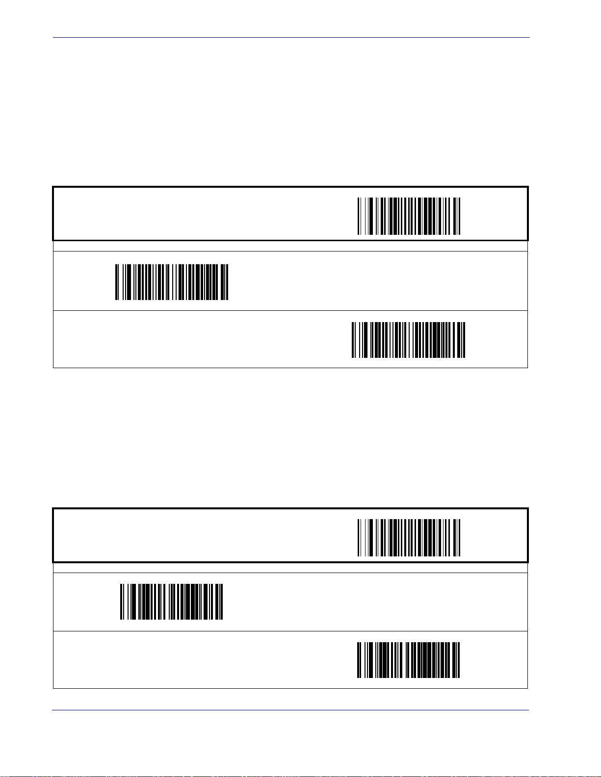
Interface Related Features
USB-OEM Interface Features
USB-OEM Device usage
The USB-OEM protocol allows for the scanner to be identified as one of two different types of
bar code scanners. Depending on what other scanners you may already have connected to a
USB-OEM POS, you may need to change this setting to enable all devices to communicate.
Options are:
• Table Top Scanner
• Handheld Scanner
START / END
PROGRAMMING bar codes
Configure as Table Top Scanner
DEFAULT
IBM
Configure as Handheld Scanner
IBM Transmit Labels in Code 39 Format
This feature enables/disables scanner's ability to set a symbology identifier for a specified label to
Code 39 before transmitting that label data to an IBM host. This applies to: Code 128, Codabar and Code 93 for USB-OEM; Code 128, Codabar and Code 93 for IBM Por
Codabar and Code 93 for IBM Port 9B.
START / END
PROGRAMMING bar codes
Disable Convert to Code 39
DEFAULT
t 5B; and
64
Enable Convert to Code 39
MagellanTM 3200VSi
Page 74
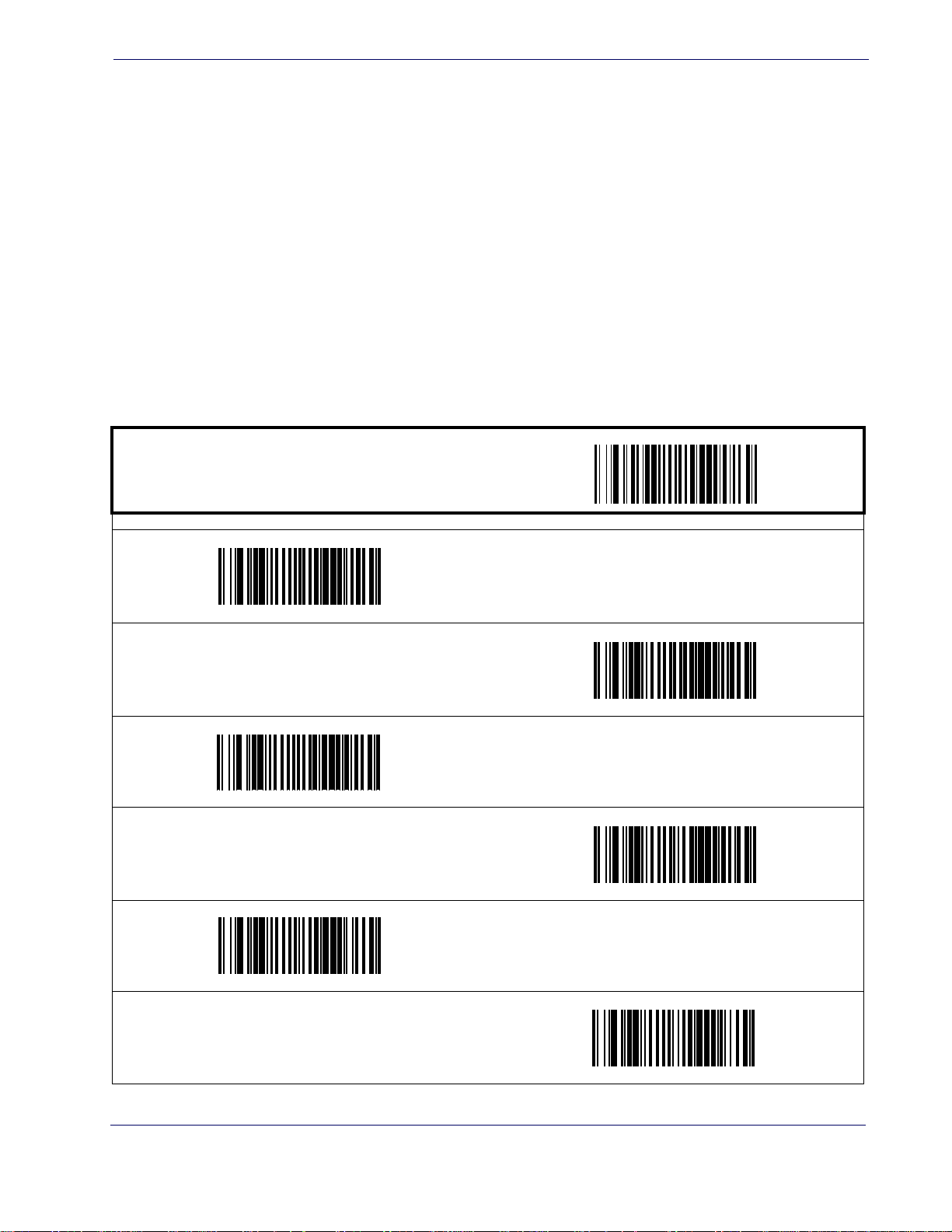
Keyboard Wedge
and
USB Keyboard
As a keyboard interface, the scanner supports most popular PCs and IBM terminals. The installation of the wedge is a fairly simple process that doesn’t re
ware.
Single Cable RS-232
quire any changes of software or hard-
All of the options in this sectio
board Wedge, however, only some apply to USB
Keyboard.
NOTE
Keyboard Layout
n apply to the Key-
The Keyboard Layout option supports many countries. For details about Keyboard Layout,
please refer to your operating system manual.
ST ART / END
PROGRAMMING bar codes
USA
DEFAULT
Belgium
Britain
Denmark
France
Germany
Product Reference Guide
65
Page 75
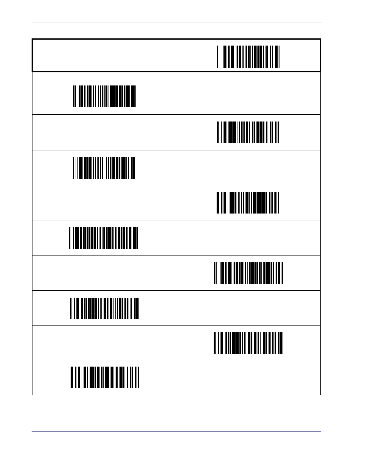
Interface Related Features
Keyboard Wedge — cont.
START / END
Norway
PROGRAMMING bar codes
Italy
Portugal
Spain
Switzerland
Hungary
Sweden
Japan 106 Key
66
Czech Republic
MagellanTM 3200VSi
Page 76
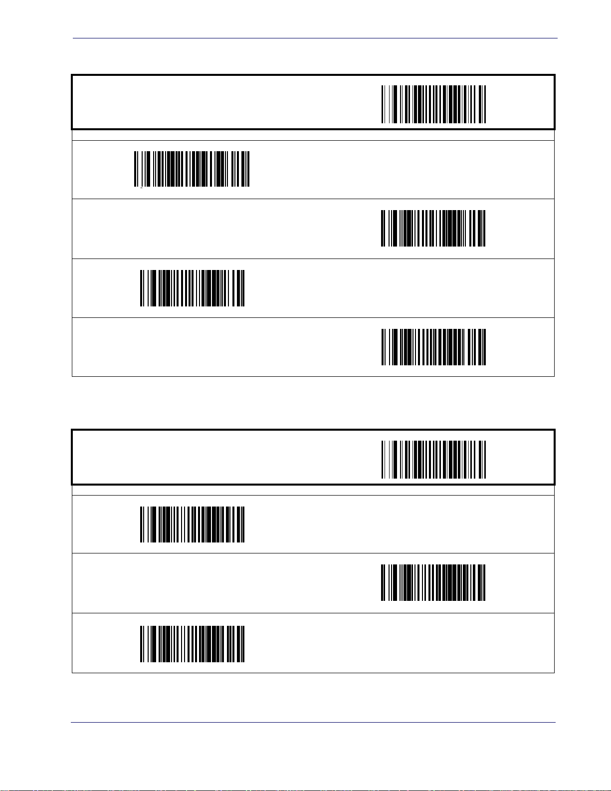
Keyboard Wedge — cont.
ST ART / END
mania
Ro
Single Cable RS-232
PROGRAMMING bar codes
Slovakia
Croatia
Poland
Caps Lock State
Specifies the format in which the scanner sends character data.
ST ART / END
PROGRAMMING bar codes
Disable Caps Lock
Caps Lock “ON”
DEFAULT
Shift Lock “ON”
Product Reference Guide
67
Page 77
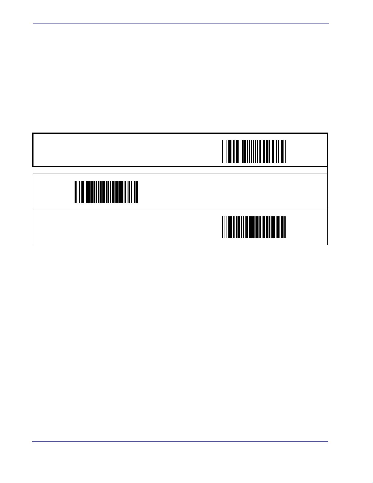
Interface Related Features
Keyboard Wedge — cont.
Power-On Simulation
This feature does not apply to the USB Keyboard
interface.
NOTE
All PCs check the keyboard status during the power-on Selftest. It is recommended that you
enable this function if you are working without a keyboard installation. It simulates keyboard
timing and passes the keyboard status to the PC during power-on.
START / END
PROGRAMMING bar codes
Disable Power-on Simulation
DEFAULT
Enable Power-on Simulation
68
MagellanTM 3200VSi
Page 78
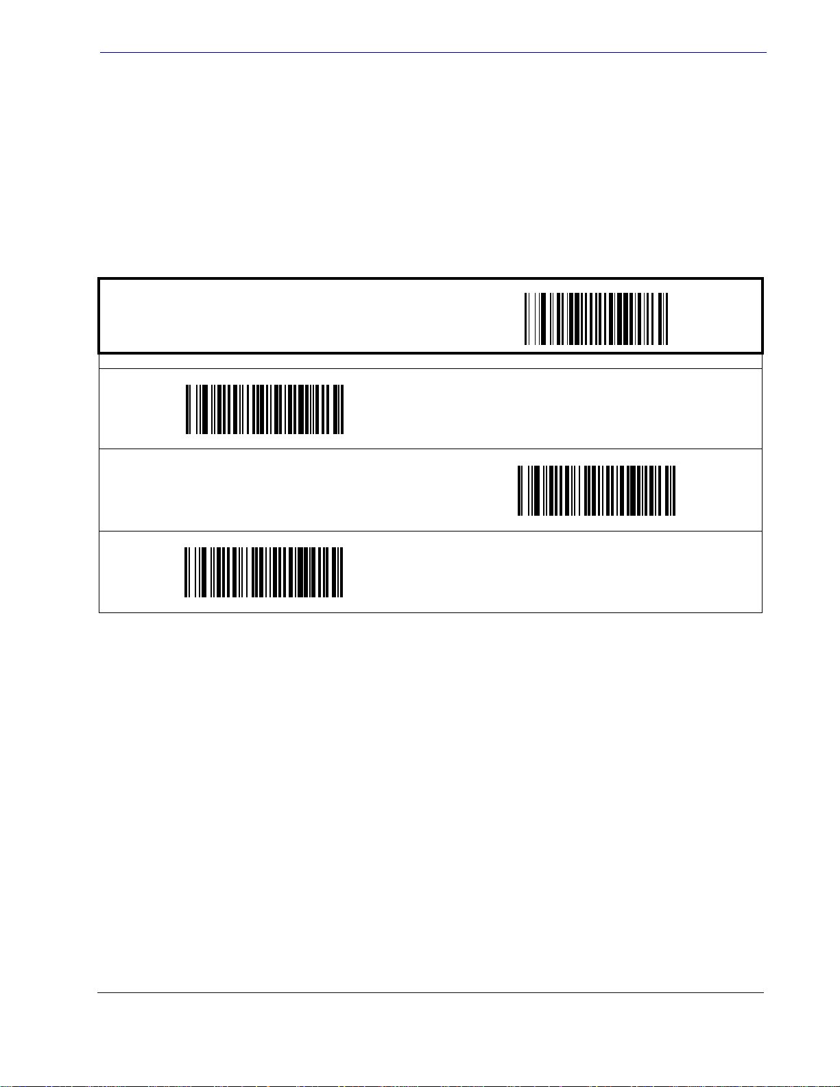
Single Cable RS-232
Control Characters
Specifies how the scanner transmits ASCII control characters to the host. Choices are:
• Disable Control Characters
• Enable transmission of control characters to host
• Send characters between 00H and 1FH according to
table. (This is used to send keys that are not in the normal ASCII set; a unique set is provided for each available scancode set. Reference
pings.)
ST ART / END
PROGRAMMING bar codes
Enable Transmission of Control Characters
a special function-key mapping
Appendix E, Keyboard Function Key Map-
Disable Control Characters
DEFAULT
Enable Function Key Mapping
Product Reference Guide
69
Page 79
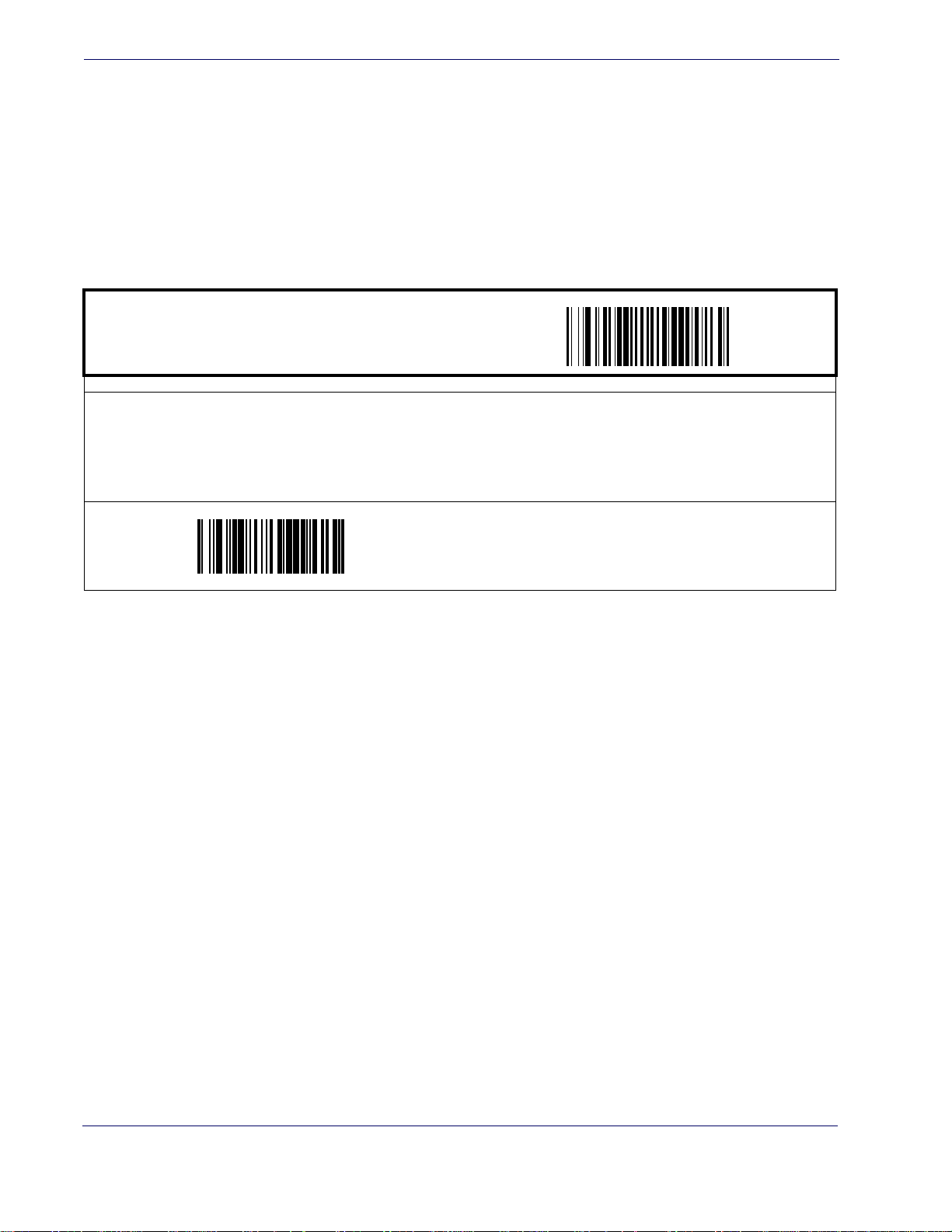
Interface Related Features
Keyboard Wedge — cont.
Wedge Quiet Interval
This feature does not apply to the USB Keyboard
interface.
NOTE
Quiet Interval is the amount of time to look for keyboard activity before the scanner breaks the
keyboard connection in order to transmit data to the host.
START / END
PROGRAMMING bar codes
Selectable from 001 to 100 in 10 msec increments. To configure this feature, scan the “START/END” bar code above to
place the unit in Programming Mode, then the Set Wedge Quiet Interval bar code followed by the three digits (zero pad-
ded) from the Alphanumeric table in Appendix C, Alpha-Numeric Pad
mode by again scanning the “START/END” bar code above.
DEFAULT SETTING FOR THIS FEATURE:
010 (100 msec)
representing your desired length. Exit programming
Set Wedge Quiet Interval
70
MagellanTM 3200VSi
Page 80
USB COM Interface Set-up
Keyboard Wedge — cont.
Intercharacter Delay
ST ART / END
PROGRAMMING bar codes
One-half of the delay specified below is inserted between scancodes within each character. If the transmission speed is
too high, the system may not be able to receive all characters. You may need to adjust the delay to make the system work
properly. Selectable from 00 to 99 in 10msec increments.
To configure this feature, scan the “START/END”
Intercharacter Delay,” followed by the two digits (zero padded) from the Alphanumeric table in Appendix C, Alpha-Numeric
Pad representing your desired length. Exit programming mode by again scanning the “START/END” bar code above/
DEFAULT SETTING FOR THIS FEATURE:
bar code above to place the unit in Programming Mode, then the “Set
00 (No Delay)
Set Intercharacter Delay
USB COM Interface Set-up
The scanner has two USB COM interfaces, USB COM and USB COM DL (Datalogic). The
Datalogic USB-COM driver works for both USB COM interfaces.
Before plugging your scanner into the Host PC, please ensure you have already copied the executable DLS-USB-COM driver file to your PC and that the scanner’
COM or USB COM DL. The DLS-USB-COM driver is provided by Datalogic or downloaded
from the Datalogic website listed on the back cover of this manual.
1. Execute the DLS-USB-COM driver file.
2. When the scanner is first plugged into the PC, Windows will bring up the “Found New
Ha
3. The installation is complete.
re” message.
rdwa
s interface is set to USB
Product Reference Guide
71
Page 81

Interface Related Features
NOTES
72
MagellanTM 3200VSi
Page 82
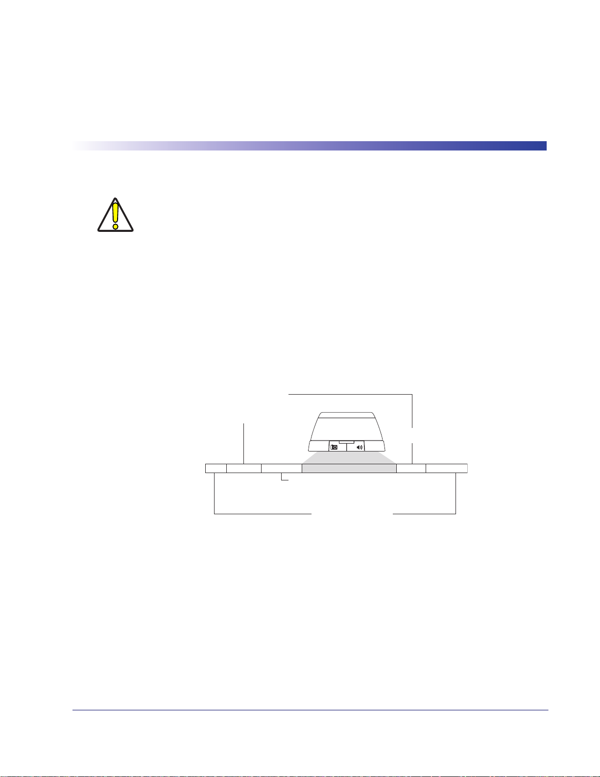
Data Editing Overview
It is not recommended to use these features with
IBM interfaces.
CAUTION
When a bar code is scanned, additional information can be sent to the host computer along
with the bar code data. This combination of bar code data and supplementary user-defined
data is called a “message string.” The features in this chapter can be used to build specific
user-defined data into a message string.
Chapter 5
Data Editing
There are several types of selectable data characters that can be sent before and
data. You can specify if they should be sent with all symbologies, or only with specific symbologies.
Figure 1 shows the available elements you can add to a message string:
Figure 1. Breakdown of a Message String
Please Keep In Mind...
• Modifying a message string is not a mandatory requirement. Data editing is sophisticated
feature allowing highly customizable output for advanced users. Factory default settings
for data editing is typically set to NONE.
Label ID Transmission:
Enable this option to
transmit the Label ID you
configure for the scanned
Prefix SuffixAIM IDLabel ID Label IDBar Code Data
symbology.
AIM ID: This function is used to identify and display the
common label identifier for its symbology. When enabled,
this ID code will be transmitted before the scanned bar
code data.
00 - 20 Characters (ASCII)
after scanned
OR...
• A prefix or suffix may be applied (reference the
• You can add any character from the
• Enter prefixes and suffixes in the order in which you want them to appear on
Product Reference Guide
Symbologies chapter for these settings)
across all symbologies (set via the Global features in this chapter).
ASCII Character Set (from 00-FF) on the inside back
cover of this manual as a prefix, suffix or Label ID.
the output.
73
Page 83
Data Editing
Global Prefix/Suffix
Up to 20 ASCII characters may be added as a prefix (in a position before the bar code data) and/
or as a suffix (in a position following the bar code data).
START / END
PROGRAMMING bar codes
Sets up to 20 characters each from the set of ASCII characters or any hex valu
scan the “START/END” bar code above to place the unit in Programming Mode, then the “Set Prefix” or “Set Suffix,” fol-
lowed by the digits from the Alphanumeric table in Appendix C, Alpha-Numeric Pad representing your desired character(s). Reference the section, Example: Setting a Prefix on page 152, for more information. Exit programming mode by
scanning the “START/END” bar code again (scan “START/END” twice
if less than 20 cha
DEFAULT SETTING PREFIX: 00 (None)
DEFAULT SETTING SUFFIX: 0D (CR)
e from 00 to FF. To configure this feature,
racters have been selected).
Set Prefix
Set Suffix
74
MagellanTM 3200VSi
Page 84
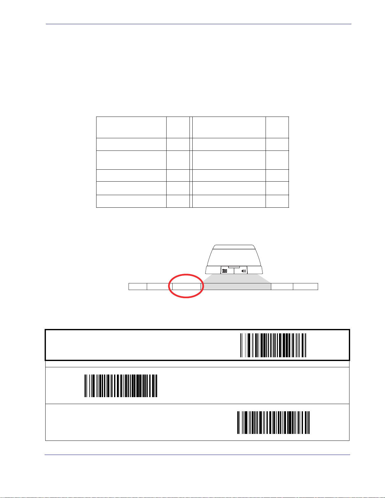
AIM ID
AIM ID
AIM (Automatic Identification Manufacturers) label identifiers are assigned from a globally
standardized list — as opposed to custom label ID characters you select yourself — and can be
included with scanned bar code data. AIM label identifiers consist of three characters as follows:
• A close brace character (ASCII ‘]’), followed by...
• A code character (see the table below), followed by...
A modifier character (the modifier character is symbol dependent)
•
SYMBOLOGY
UPC/EAN E
Code 39 A
abar F Stan dard 2 of 5 S
Cod
Interleaved 2 of 5 I ISBN
Code 93
a. ISBN (X with a 0 modifier character)
CHA
R
G
SYMBOLOGY
Code 128/EAN 128
GS1 Omnidirectional,
GS1 Exp
anded
Figure 2. AIM ID
Prefix SuffixLabel ID Label IDBar Code DataAIM ID
CHA
R
C
e
a
X
ST ART / END
PROGRAMMING bar codes
Disable AIM ID
DEFAULT
Enable AIM ID
Product Reference Guide
75
Page 85
Data Editing
Label ID
See Label ID on page 153 for more information on setting this feature.
START / END
Label ID Position: Before Bar Code Data
DEFAULT
PROGRAMMING bar codes
Label ID Transmission: Disable
Label ID Position
Label ID Position: After Bar Code Data
Set UPC-A Label ID Character(s)
DEFAULT SETTING FOR THIS FEATURE: A (41
hex)
Set UPC-A w/P5 Addon Label ID Character(s)
DEFAULT SETTING FOR THIS FEATURE: A (41
hex)
Set UPC-E Label ID Character(s)
DEFAULT SETTING FOR THIS FEATURE: A (41 hex)
Set UPC-A w/P2 Addon Label ID Character(s)
DEFAULT SETTING FOR THIS FEATURE: A (41 hex)
Set UPC-A w/C128 Addon Label ID Character(s)
DEFAULT SETTING FOR THIS FEATURE: E (45 hex)
76
MagellanTM 3200VSi
Page 86
Label ID — cont.
ST ART / END
PROGRAMMING bar codes
DEFAULT SETTING FOR THIS FEATURE: E (45 hex)
Set UPC-E w/P5 Addon Label ID Character(s)
DEFAULT SETTING FOR THIS FEATURE: E (45 hex)
Label ID
Set UPC-E w/P2 Addon Label ID Character(s)
DEFAULT SETTING FOR THIS FEATURE: E (45 hex)
Set UPC-E w/C128 Addon Label ID Character(s)
Set EAN-8 Label ID Character(s)
DEFAULT SETTING FOR THIS FEATURE: FF (4646
hex)
Set EAN-8 w/P5 Addon Label ID Character(s)
DEFAULT SETTING FOR THIS FEATURE: FF (4646
hex)
Set EAN-13 Label ID Character(s)
DEFAULT SETTING FOR THIS FEATURE: FF (4646
hex)
Set EAN-8 w/P2 Addon Label ID Character(s)
DEFAULT SETTING FOR THIS FEATURE: FF (4646
hex)
Set EAN-8 w/C128 Addon Label ID Character(s)
DEFAULT SETTING FOR THIS FEA TURE: F (46 hex)
Product Reference Guide
77
Page 87
Data Editing
Label ID — cont.
START / END
PROGRAMMING bar codes
DEFAULT SETTING FOR THIS FEATURE: F (46 hex)
Set EAN-13 w/P5 Addon Label ID Character(s)
DEFAULT SETTING FOR THIS FEATURE: F (46 hex)
Set EAN-13 w/P2 Addon Label ID Character(s)
DEFAULT SETTING FOR THIS FEA TURE: F (46 hex)
Set EAN-13 w/C128 Addon Label ID Character(s)
Set ISBN Label ID Character(s)
DEFAULT SETTING FOR THIS FEATURE: IA (4941
hex)
Set GTIN Label ID Character(s)
DEFAULT SETTING FOR THIS FEATURE: G2 (4732
hex)
Set GTIN w/P5 addon Label ID Character(s)
DEFAULT SETTING FOR THIS FEATURE: I (49 hex)
Set IATA Label ID Character(s)
DEFAULT SETTING FOR THIS FEATURE: G (47
hex)
Set GTIN w/P2 addon Label ID Character(s)
78
DEFAULT SETTING FOR THIS FEATURE: G5 (4735
hex)
MagellanTM 3200VSi
Page 88
Label ID — cont.
ST ART / END
PROGRAMMING bar codes
DEFAULT SETTING FOR THIS FEATURE: G8 (4738
hex)
Set GS1 Omnidirectional Label ID Character(s)
Label ID
Set GTIN w/C128 addon Label ID Character(s)
DEFAULT SETTING FOR THIS FEATURE: R4 (5234
hex)
DEFAULT SETTING FOR THIS FEATURE: RX (5258
hex)
Set Code GS1 DataBar Limited Label ID Character(s)
DEFAULT SETTING FOR THIS FEA TURE: * (2A hex)
Set Pharmacode 39 Label ID Character(s)
Set GS1 Expanded Label ID Character(s)
DEFAULT SETTING FOR THIS FEATURE: *
(524C0000 hex)
Set Code 39 Label ID Character(s)
DEFAULT SETTING FOR THIS FEATURE: A (41 hex)
Set Code 128 Label ID Character(s)
DEFAULT SETTING FOR THIS FEATURE: # (23 hex)
Set I 2 of 5 Label ID Character(s)
DEFAULT SETTING FOR THIS FEATURE: i (69 hex)
Product Reference Guide
79
Page 89
Data Editing
Label ID — cont.
START / END
PROGRAMMING bar codes
DEFAULT SETTING FOR THIS FEATURE: % (25
hex)
Set Code 93 Label ID Character(s)
DEFAULT SETTING FOR THIS FEATURE: @ (40
hex)
Set Codabar Label ID Character(s)
DEFAULT SETTING FOR THIS FEATURE: & (26 hex)
Set Code 11 Label ID Character(s)
Set EAN UCC Composite Label ID Character(s)
DEFAULT SETTING FOR THIS FEATURE: 0
Set PDF 417 Label ID Character(s)
DEFAULT SETTING FOR THIS FEATURE: P (5000
a
hex)
Set Datamatrix Label ID Character(s)
DEFAULT SETTING FOR THIS FEATURE: Dm (446D
hex)
Set MSI Label ID Character(s)
DEFAULT SETTING FOR THIS FEATURE: @ (40
hex)
a.
Default setting exceptions for PDF 417 Label ID are as follows: Default for RS-232 WN is ‘Q’ (0x5100). Default for USB-HIDPOS is ‘P ‘ (0x5020), or ‘P-Space’.
80
MagellanTM 3200VSi
Page 90
Label ID — cont.
Label ID
For the 2D symbologies on this page, the Label ID is 4 bytes . The first 3
bytes are characters for the label ID. A 00 (hex) value in the first 3 by tes
indicates the end of the label ID characters. The 4th byte is a control byte.
NOTE
The use of the control byte is as follows:
bit 0-if set to 1, the AIM ID is appended for that label type
ST ART / END
PROGRAMMING bar codes
DEFAULT SETTING FOR THIS FEATURE: mP
(6D500000 hex)
Set QR Code Label ID Character(s)
DEFAULT SETTING FOR THIS FEATURE: MC
(4D430000 hex)
Set Micro PDF 417 Label ID Character(s)
DEFAULT SETTING FOR THIS FEATURE: QR
(51520000 hex)
Set Maxicode Label ID Character(s)
Set Aztec Label ID Character(s)
DEFAULT SETTING FOR THIS FEATURE: Az
(417A0000 hex)
Set GS1 DataBar Omnidirectional 2D Composite
Label ID Character(s)
DEFAULT SETTING FOR THIS FEATURE: R4
(52340000 hex)
Set GS1 DataBar Limited 2D Composite
Label ID Character(s)
DEFAULT SETTING FOR TH IS FEATURE: RL
(524C0000 hex)
Set GS1 DataBar Expanded 2D Composite
Label ID Character(s)
DEFAULT SETTING FOR THIS FEATURE: RX
(52340000 hex)
Product Reference Guide
81
Page 91
Data Editing
Case Conversion
This feature can convert scanned bar code data to either all lower case (a through z) or all upper
case (A through Z) characters.
NOTE
START / END
Convert to Upper Case
Case conversion affects ONLY scanned bar code
data, a
nd does not affect Label ID, Prefix, Suffix, or
other appended data.
PROGRAMMING bar codes
Disable
DEFAULT
Convert to Lower Case
82
MagellanTM 3200VSi
Page 92

Character Conversion
Character conversion is an eight byte configuration item. The eight bytes are 4 character pairs
represented in hexadecimal ASCII values. The first character in the pair is the character that
will be converted. The second character in the pair is the character to convert to. If the character to convert in a pair is FF, then no conversion is done.
example, if you have the character conversion configuration item set to the following:
For
41423132FFFFFFFF
Character Conversion
The first pair is 414
2 or AB (41
hex is an ASCII capital A, 42 hex is an ASCII capital B) and
the second pair is 3132 or 12 (31 hex is an ASCII 1, 32 is an ASCII 2). The other two pairs
are FFFF and FFFF.
With the label, AG15TA81, it would look as follows after the character conversion:
25TB82.
BG
The A ch
aracters were converted to the B character and the 1 charac
ters were converted to the
numeral 2 character. Nothing is done with the last two character pairs, since they are all FF.
To set Character Conversion:
1. Scan the START/END bar code.
2. Scan the Character Conversion bar code.
3. Determine the desired string. Up to sixteen position
example. Next, turn to the
ASCII Character Set on the inside back cover of this manual and
s can be determined as in
the above
find the equivalent hex digits needed to fulfill the string.
The positions not used must be filled with the character ‘F’.
NOTE
4. Turn to Appendix C, Alpha-Numeric Pad and scan the bar codes representing the hex characters determined in the previous step. When the last character is scanned, the scanner will
sound a triple beep.
5. Scan the ST
ST ART / END
DEFAULT SETTING FOR THIS FEATURE:
FFFFFFFFFFFFFFFF hex (no conversion)
Product Reference Guide
ART/END bar code to exit Programming Mode.
PROGRAMMING bar codes
Character Conversion
83
Page 93

Data Editing
NOTES
84
MagellanTM 3200VSi
Page 94
Chapter 6
Symbologies
The scanner supports the following symbologies (bar code types). Options for each symbology
are included in this chapter.
• UPC-A • Code 39
• UPC-E
• EAN-13 • Code 128
• EAN-8 • Interleaved 2 of 5
• GS1 DataBar Omnidirectional /
Stacked Omnidirectional
• GS1 DataBar Expanded /
Expanded Stacked
• GS1 DataBar Limited • MSI
• Code 32 Italian
Pharmacode
• Codabar
• Code 93
Factory Defaults—
section. Reference
UPC-A
Disable/Enable UPC-A
When disabled, the scanner will not read UPC-A bar codes.
ST ART / END
Enable UPC-A
DEFAULT
for the standard RS-232 interface are indicated in bold text throughout this
Appendix D, Factory Default Settings for default exceptions for your interface.
PROGRAMMING bar codes
Disable UPC-A
Product Reference Guide
85
Page 95
Symbologies
UPC-A — cont.
Check Digit Transmission
Enable this option to transmit the check digit along with UPC-A bar code data.
START / END
Send Check Digit
DEFAULT
PROGRAMMING bar codes
Don’t Send Check Digit
Number System Transmission
This feature enables/disables transmission of UPC-A System Number.
START / END
Enable Number System Transmission
DEFAULT
PROGRAMMING bar codes
Disable Number System Transmission
86
MagellanTM 3200VSi
Page 96
UPC-A — cont.
Expand UPC-A to EAN-13
Expands UPC-A data to the EAN-13 data format. Selecting this feature also changes the symbology ID to match those required for EAN-13.
ST ART / END
Expand to EAN-13
UPC-A
PROGRAMMING bar codes
Don’t Expand to EAN-13
DEFAULT
Product Reference Guide
87
Page 97
Symbologies
UPC-E
The following options apply to the UPC-E symbology.
Disable/Enable UPC-E
When disabled, the scanner will not read UPC-E bar codes.
START / END
Enable UPC-E
DEFAULT
PROGRAMMING bar codes
Disable UPC-E
Check Digit Transmission
Enable this option to transmit the check digit along with UPC-E bar code data.
START / END
Send Check Digit
DEFAULT
PROGRAMMING bar codes
Don’t Send Check Digit
88
MagellanTM 3200VSi
Page 98
UPC-E — cont.
Number System Digit
The Number System Digit (NSD) which is always a zero (0) in the leading position can be
optionally included (or not) with scanned bar code data.
ST ART / END
Include Number System Digit
UPC-E
PROGRAMMING bar codes
Exclude Number System Digit
DEFAULT
Expand to UPC-E to UPC-A
Enables/disables expansion of UPC-E labels to UPC-A. Selecting this feature also changes the
symbology ID to match those required for UPC-A.
ST ART / END
Expand UPC-E to UPC-A
PROGRAMMING bar codes
Don’t Expand UPC-E to UPC-A
DEFAULT
Product Reference Guide
89
Page 99
Symbologies
UPC-E — cont.
Expand UPC-E to EAN13
Enables/disables expansion of UPC-E labels to EAN-13. Selecting this feature also changes the
symbology ID to match those required for EAN-13.
START / END
Expand UPC-E to EAN-13
PROGRAMMING bar codes
Don’t Expand UPC-E to EAN-13
DEFAULT
90
MagellanTM 3200VSi
Page 100
GTIN
The following options apply to the GTIN label data format.
Expand UPC/EAN to GTIN
When this feature is enabled, the scanner will translate UPC/EAN labels to the 14 digit GTIN
format.
ST ART / END
Expand to GTIN
UPC-E
PROGRAMMING bar codes
Don’t Expand to GTIN
DEFAULT
Product Reference Guide
91
 Loading...