

Page 1
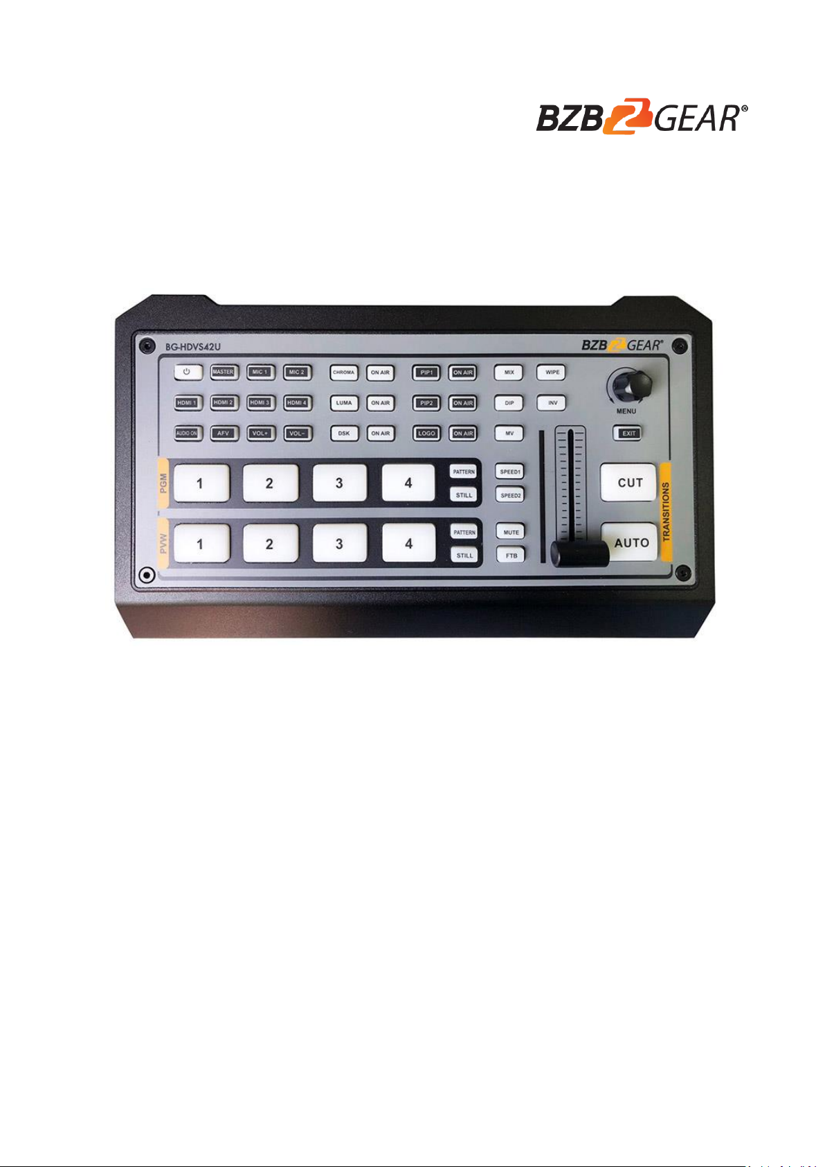
BG-HDVS42U
MICRO 4 CHANNEL HDMI LIVE STREAM
MULTI-FORMAT VIDEO SWITCHER
Page 2

USING THE UNIT SAFELY
Before using this unit, please carefully review the following information concerning the proper operation
of the unit. To ensure that you are getting the most out of your product review the manual in its entirety.
This manual should be saved and kept on hand for future reference.
Warning and Precautions
※ To avoid damage from drops, make sure this unit is placed on a stable and solid surface.
※ Only connect unit with the included power supply.
※ Disconnect power cord by connector only - Do not pull on the cable.
※ Do not place or drop heavy or sharp-edged objects on power cord. A damaged cord can cause fire or
electrical shock hazards. Regularly check power cord for excessive wear or damage to avoid possible
fire / electrical hazards.
※ Ensure the unit is properly always grounded to prevent electrical shock hazard.
※ Do not use this unit near water.
※ Do not allow liquids, metal pieces, or other foreign materials to enter the unit.
※ Handle with care to avoid shocks in transit. Shocks may cause malfunction. When you need to
transport the unit, use the original packing materials or alternate adequate packing.
※ Do not remove covers, panels, casing, or access circuitry! Internal servicing / adjustment of unit
should only be performed by qualified personnel.
※ Turn off the unit if a malfunction occurs. Disconnect everything before moving the unit.
Note: Due to the constant effort to improve our products and product features, specifications may change
without notice.
Page 3

CONTENTS
1. BRIEF INTRODUCTION ........................................................................................... 1
1.1. Overview ........................................................................................................................... 1
1.2. Main Features................................................................................................................... 1
2. INTERFACES ............................................................................................................ 2
2.1. Interface Overview ........................................................................................................... 2
2.2. Tally PIN Definition .......................................................................................................... 2
3. SPECIFICATION ....................................................................................................... 3
4. FRONT CONTROL PANEL ...................................................................................... 4
5. POWER ON/ OFF ...................................................................................................... 5
6. MULTIVIEW ............................................................................................................... 6
6.1. Status Page ...................................................................................................................... 6
6.2. Layouts .............................................................................................................................. 7
6.3. Audio Meter....................................................................................................................... 8
6.4. Input Information .............................................................................................................. 8
6.5. UMD Settings ................................................................................................................... 9
7. PGM PVW SWITCHING .................................................................................................. 10
7.1. PGM PVW Channel Selection ..................................................................................... 10
7.2. STILL ............................................................................................................................... 10
7.3. Transition: CUT/ AUTO/ T-BAR................................................................................... 11
8. TRANSITION EFFECT ............................................................................................ 11
8.1. WIPE ................................................................................................................................ 11
8.2. DIP ................................................................................................................................... 11
8.3. MIX ................................................................................................................................... 12
8.4. Transition Speed Setting .............................................................................................. 12
9. UPSTREAM KEY .................................................................................................... 12
9.1. Luma Key ........................................................................................................................ 12
9.2. Chroma key..................................................................................................................... 13
9.3. PIP & POP ...................................................................................................................... 15
10. DOWNSTREAM KEY ............................................................................................ 16
10.1. DSK ................................................................................................................................ 16
10.2. LOGO ............................................................................................................................ 17
11. OUTPUT SETTING ............................................................................................... 18
Page 4

11.1. Output Interfaces ......................................................................................................... 18
11.2. Multiview Out ................................................................................................................ 18
11.3. PGM Out ....................................................................................................................... 18
11.4. USB Out ........................................................................................................................ 18
11.5. Output Format Setting................................................................................................. 19
11.6. FTB ................................................................................................................................ 20
12. AUDIO SETTING ................................................................................................... 21
12.1. Master Audio ................................................................................................................ 21
12.2. Audio On (MIX) ............................................................................................................ 21
12.3. AFV ................................................................................................................................ 21
12.4. Audio Delay .................................................................................................................. 22
12.5. MIC................................................................................................................................. 22
12.6. Earphone....................................................................................................................... 22
12.7. Audio Keyboard Configuration................................................................................... 23
12.8. Mute ............................................................................................................................... 24
13. MEDIA LIBRARY .................................................................................................. 25
13.1. PVW Pattern & PGM Pattern ..................................................................................... 25
13.2. User-defined Color Pattern ........................................................................................ 25
13.3. Image Setting ............................................................................................................... 25
14. SYSTEM SETTING ............................................................................................... 27
14.1. Language ...................................................................................................................... 27
14.2. Fan Setting ................................................................................................................... 27
14.3. System Reset ............................................................................................................... 27
14.4. Download ...................................................................................................................... 27
14.5. Version .......................................................................................................................... 27
14.6. Time Setting ................................................................................................................. 27
14.7. Network Setting ............................................................................................................ 28
14.8. User Setting .................................................................................................................. 28
WARRANTY / MISSION STATEMENT……………………………………………...…..30
Page 5
1
1. BRIEF INTRODUCTION
1.1. Overview
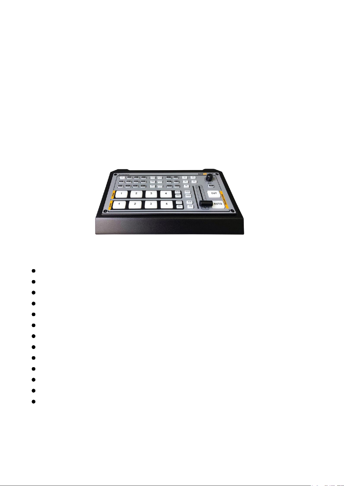
The BG-HDVS-42U is a 4-channel HDMI multi-format video Switcher with a compact metal case design.
It supports various functions including video switching, audio mixing, PGM/ Multiview/ Aux out, different
transition effects, Luma Key, Chroma Key, DSK, LOGO, PIP/ POP, media library, pattern, and color
generator, and more. Inputs support multi-formats and the PGM output can be scaled, ensuring
compatibility with a variety of equipment. The unit supports streaming and presentations on PC via the
USB-C port. User can also customize different settings and import or export the configuration quickly for
various scenarios. Powerful and Portable this professional video switcher is an ideal choice for any smallscale HDMI production.
1.2. Main Features
4 channel auto-detected HDMI inputs
1×HDMI PGM output,1×HDMI Multiview out, 1×USB type-C output
AUX output configurable and assignable
USB-C for capturing and streaming on PC
Clear and uncluttered Multiview & status page
Upstream key: Luma key, Chroma key, PIP×2/ POP
Downstream key and LOGO overlay
T-bar/ Auto/ Cut transitions; various effects: WIPE (9×2 patterns) / MIX/ DIP
Audio mixer: HDMI embedded audio and 2-Ch MIC/ line in; audio delay available
Media library: 49 default patterns, 16 imported images, 16 captured images, 2 color generators
LAN port for PC software remote control
Custom configuration import and export
FTB/ MUTE/ STILL/ GPIO for tally
Page 6
2
2. INTERFACES
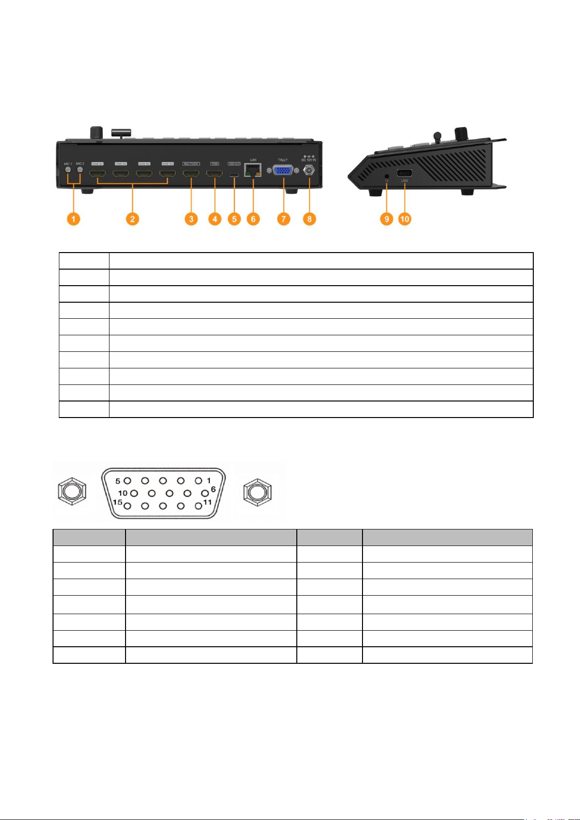
2.1. Interface Overview
1
MIC/Line level IN × 2
2
HDMI IN × 4
3
MULTIVIEW(AUX) OUT × 1
4
PGM(AUX) OUT × 1
5
USB OUT × 1 (for live streaming on PC)
6
LAN port for PC software control
7
GPIO (for tally)
8
DC 12V IN × 1
9
Earphone OUT × 1
10
USB type-A × 1 (insert U disk to import images and LOGO; firmware upgrade)
2.2. Tally PIN Definition
PIN
Definition
PIN
Definition
11
PGM-IN1
6
PVW-IN1
12
PGM-IN2
7
PVW-IN2
13
PGM-IN3
8
PVW-IN3
14
PGM-IN4
9
PVW-IN4
15
NC
10
NC
3
NC 4 NC
5
GND
Page 7
3
3. SPECIFICATION
CONNECTION
Video In
HDMI type-A ×4
Video Out
HDMI type-A PGM ×1
HDMI type-A Multiview ×1
USB2.0 type C ×1 (Streaming on PC)
Assignable HDMI 1~4, PGM, Clean PGM, PVW, Color bar, Multiview
Audio In
MIC/ Line level (3.5mm stereo audio) ×2
PC Control Port
LAN×1
Media Library
USB type-A ×1(USB disk port for image import and firmware upgrade)
Tally Port
DB-15 ×1
Power In
DC 12V ×1
FUNCTIONS
Transitions
T-Bar/AUTO/ CUT
Effects
Wipe (9×2 patterns)/ Mix/ DIP/ Pattern/ Still(freeze)/ MUTE/ FTB
Layouts
2 styles of Multiview layout (6 windows and status)
Keys
Upstream Key: Luma Key ×1/ Chroma Key ×1/ PiP ×2/ POP
Downstream Key: DSK ×1/ Logo ×1
Audio Mixer
HDMI ×4 and MIC/ Line level ×2;
Audio delay: 0-500ms
Media
Default image: 49 preset patterns
Local image: up to 16 imported images
Capture image: up to 16 captured images
Generators
Pattern generator ×1
Color generators ×2
STANDARDS
HDMI In Format
Support
1080p 60/ 59.94/ 50/ 30/ 29.97/ 25/ 24/ 23.98
1080i 50/ 59.94/ 60
720p 60/ 59.94 /50/ 30/ 29.97/ 25/ 24/ 23.98
576i 50, 576p 50, 480p 59.94/ 60, 480i 59.94/ 60
HDMI PGM Out
1080p 60/ 59.94/ 50/ 48/ 47.95/ 30/ 29.97/ 25/ 24/ 23.98; 1080i 60/ 59.94/ 50
HDMI Multiview Out
1080p 60/ 59.94/ 50/ 48/ 47.95/ 30/ 29.97/ 25/ 24/ 23.98; 1080i 60/ 59.94/ 50
HDMI Color Space
RGB/ YUV
USB Capture Out
MJPG, Up to 1080p 60
Media Format
USB disk format support: FAT32, Ext3, Ext4, up to 256GB
Page 8
4
Image format support: png, bmp, jpg
Logo format support: png, bmp, jpg;
Logo size support: 10×10 pixel to 600×600 pixel
OTHERS
Power
Wide voltage: 7~24V; Operating power:12W (12V 1A)
Dimension (LWD)
244.5 × 143.2 × 44.5mm
Weight
Net: 1030g; Gross: 1500g
Temperature
Working: -20℃~60℃, Storage: -30℃~70℃
Accessories
Power supply (12V 2A) ×1; USB cable (type A-C) ×1; Tally connector (DB-15)
×1
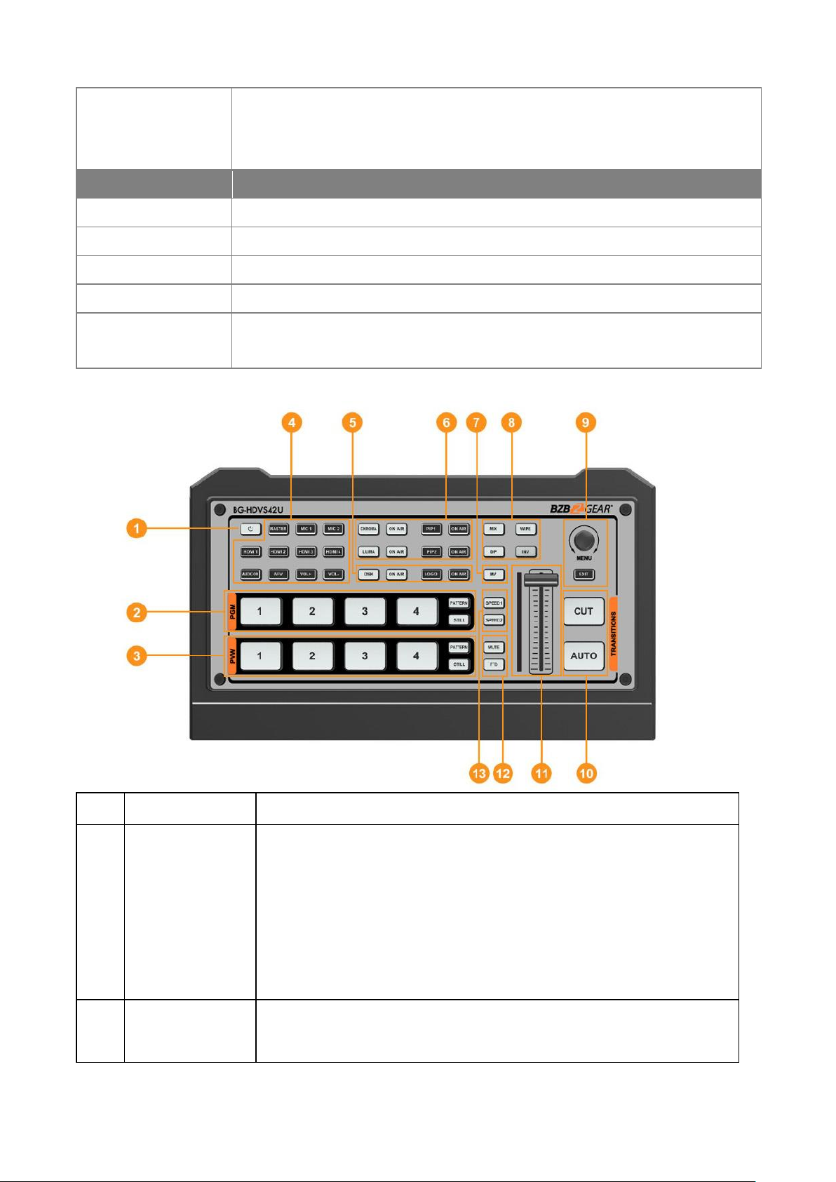
4. FRONT CONTROL PANEL
1
Power
Press the power to start the device; Press 3s to shut down the system
2
PGM:1-4
Select the signal source for Program.
PATTERN displays a test pattern to PGM output, STILL freezes the input
source image.
Note: different patterns can be set including Black/Color Bar/Color1
/Color2/ HDMI In1/HDMI In2/HDMI In3/HDMI In4/Image. (Refer to Part
13.1)
3
PVW:1-4
Select the signal source for Preview.
PATTERN displays a test pattern to PVW (Refers to Part 13.1), STILL
Page 9
5
freezes the input source image (Refer to Part 7.2).
4
AUDIO
Configure the audio of each channel, including AFV or audio mix mode,
audio source selecting, volume + & volume -
5
DSK
DSK: Enable the downstream key
ON AIR: Put the DSK on air
6
CHROMA KEY
LUMA KEY
CHROMA: Enable the Chroma Key
LUMA: Enable the Luma Key
PIP1/PIP2: Enable two group of Picture in Picture. Size and position can
be set via Menu.
LOGO: Add logo bin from USB flash disk, enable the logo overlay
ON AIR: Put the corresponding Chroma/Luma/PIP/Logo on air.
7
MV
MV: quickly switch between Multiview and the configured Multiview out
(Refer to Part 11.2)
8
Transition
Effects
WIPE: Transition from one source to another
INV: Invert the direction of selected wipe transition
MIX: Selects a basic A/B dissolve for the next transition
DIP: Gradual transition from one source to another.
9
MENU
MENU: For menu control, configure different parameters
10
CUT/ AUTO
CUT: Performs a simple immediate switch between Program and
Preview.
AUTO: Performs an automated switch between Program and Preview.
11
T-Bar
Switch the PVW and PGM using the T-Bar
12
MUTE/ FTB
MUTE: Mute the master audio
FTB: Fade to Black
13
Speed
SPEED 1-2: Control transition rate, speed can be configured on Menu.
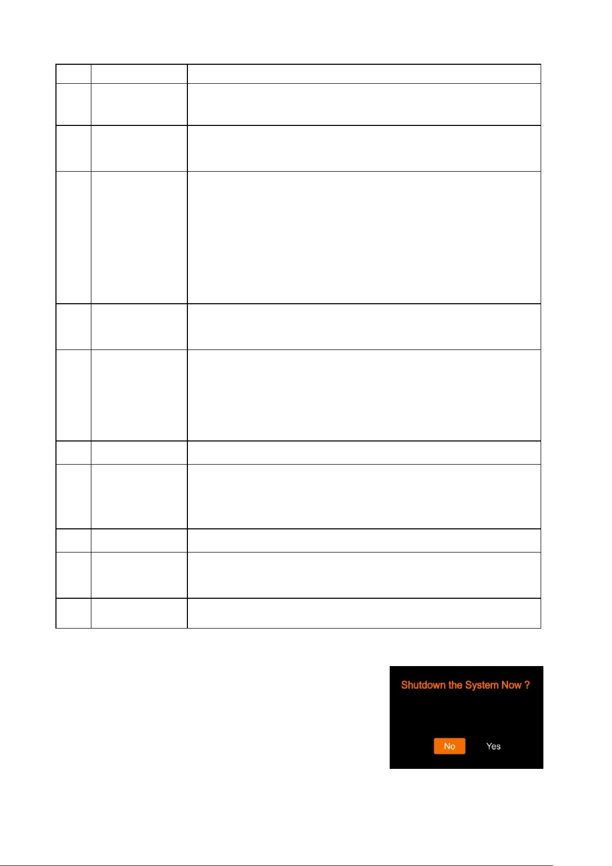
5. POWER ON/ OFF
Connect your video sources, output devices, and simply plug in the
power adapter. Press the power button on the front panel to power
up the switcher.
Press the power button for about 3 seconds to power off the switcher
and select YES in the prompt box to shut down the system.
Page 10
6
6. MULTIVIEW
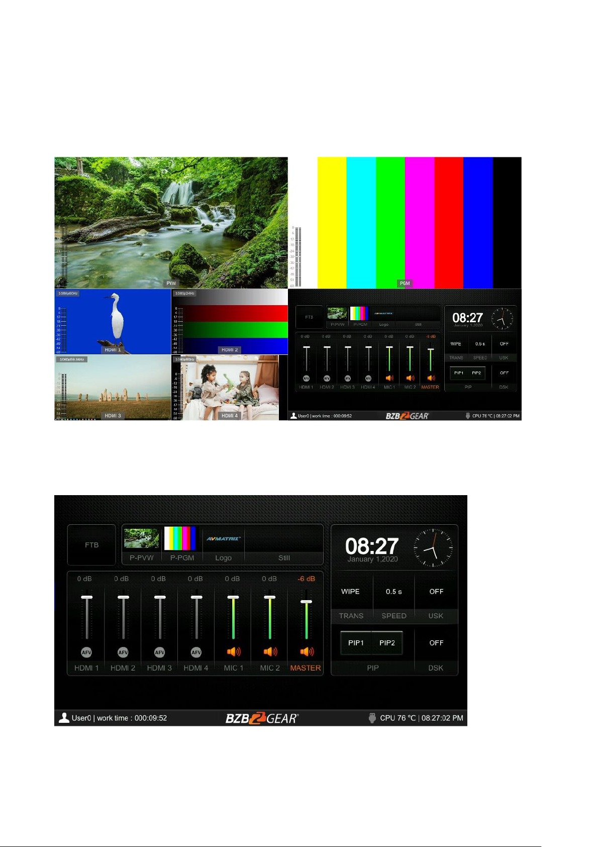
The switcher provides two HDMI outputs (PGM/Multiview). Both ports are assignable AUX outputs that are
user assignable as HDMI 1/ HDMI 2/ HDMI 3/ HDMI 4/ PGM/ Clean PGM/ PVW/ Color Bar/ Multiview
output (Refers to Part 6). Connecting the HDMI Multiview out to an additional monitor will provide the
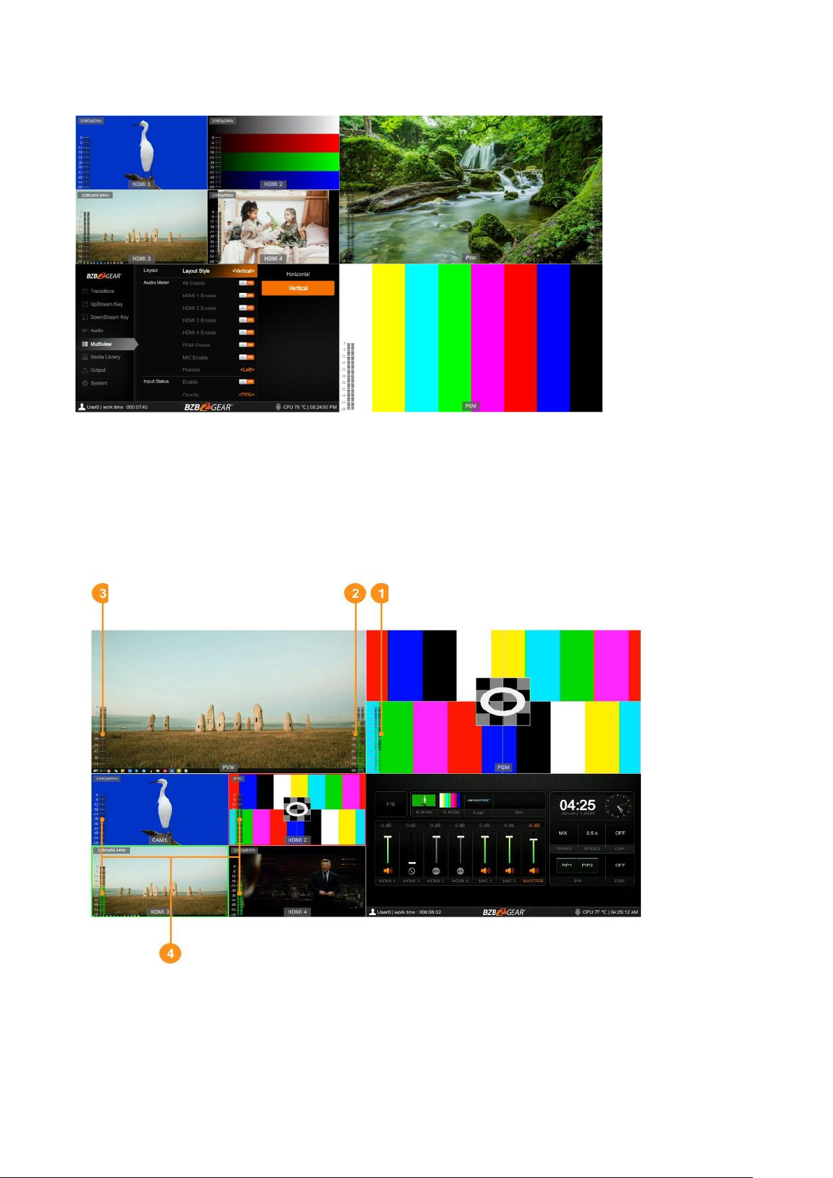
Multiview image. In Multiview there are windows of PVW, PGM, HDMI 1, HDMI 2, HDMI 3, HDMI4 and
Status/Menu page. See below image.
6.1. Status Page
In the status page, there is status information of FTB (Fade to Black), P-PVW (Pattern in PVW row), PPGM (Pattern in PGM row), Logo, Still, Audio, Transition Effect, Transition Speed, USK (Upstream Key),
DSK (Downstream Key), and System Time. See below image.
The information of username, working time, USB connection, CPU working temperature, system time
keeps displaying in the bottom of the Status/Menu page.
Page 11
7
The information on the status page will be updated in real time as the settings are changed.
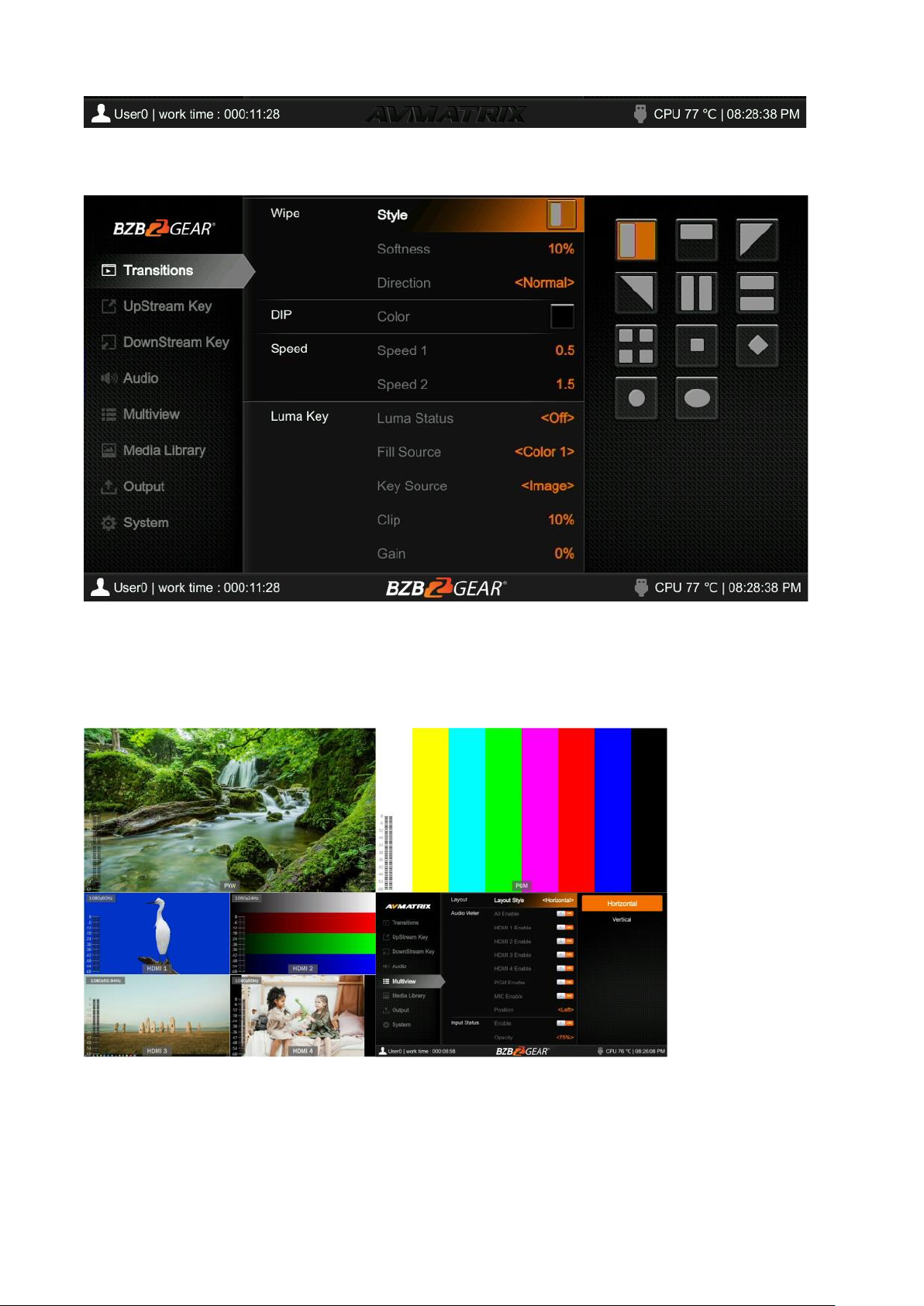
Pressing the menu button on the switcher will open the menu page as shown in the image below.
6.2. Layouts
There are two Multiview layouts which can be selected. Simply switch between the horizontal layout and
vertical layout from the menu as shown in the images below.
Horizontal:
Page 12
8
Vertical:
6.3. Audio Meter
There are audio meters in each window of the Multiview, including HDMI1-4, PGM and MIC to show the
audio level of each input. The audio meters of MIC 1 and MIC 2 show in the left and right of PVW window.
Users can turn on/off all or individual audio meters from the menu. The audio meter position can be
displayed in the right or left of each window. See below image.
6.4. Input Information
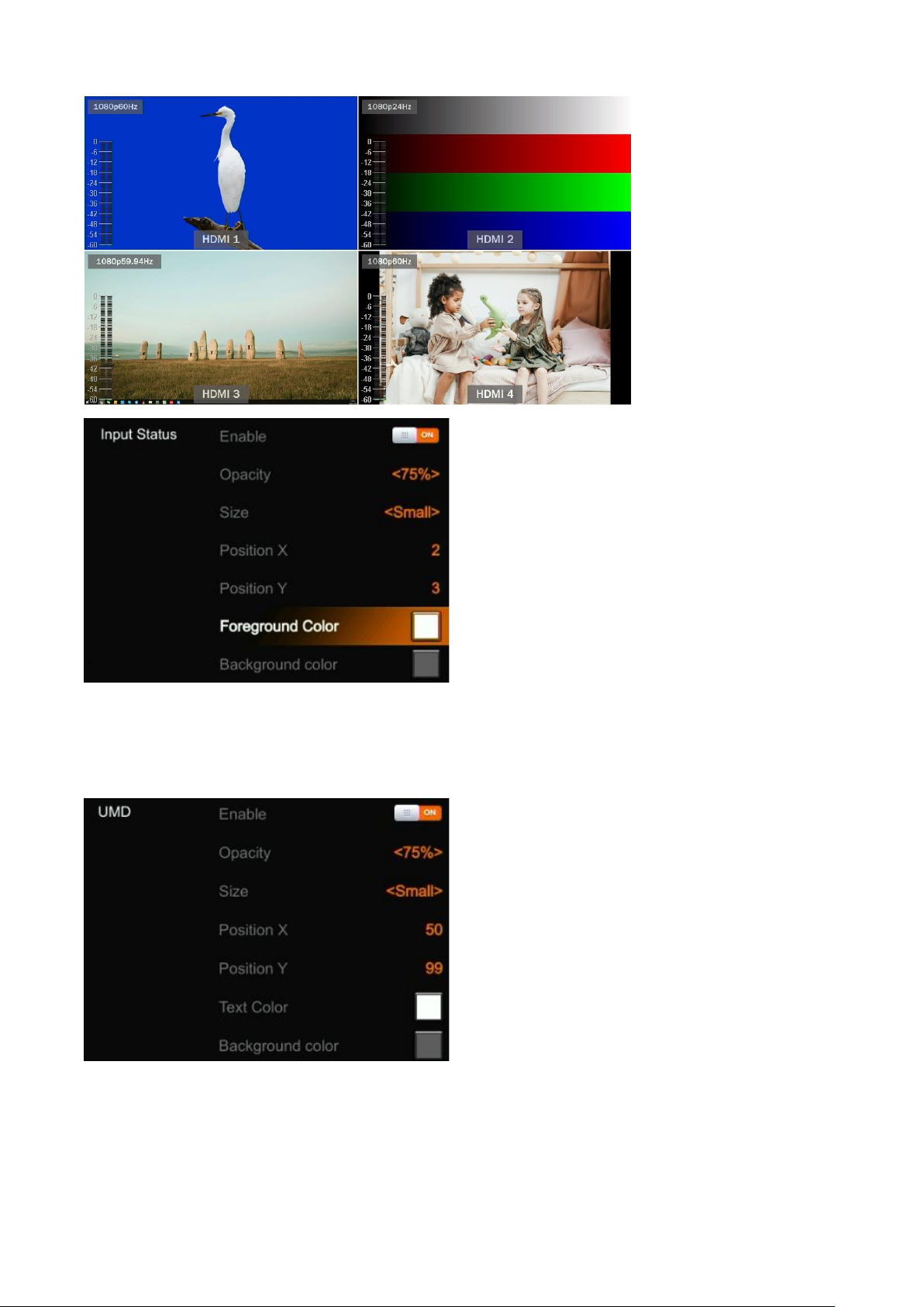
There is an overlay in each window of HDMI inputs 1-4. The overlay shows the resolution and frame rate
of the HDMI input. Users can turn on/off the overlay in each input window. Users can also set the overlay
Opacity (50%, 75%, 100%), Size (Small/Medium/Large), Position X & Y (1-100), Foreground color and
Background Color. See below image.
Master Audio
MIC1
MIC2
Page 13
9
6.5. UMD Settings
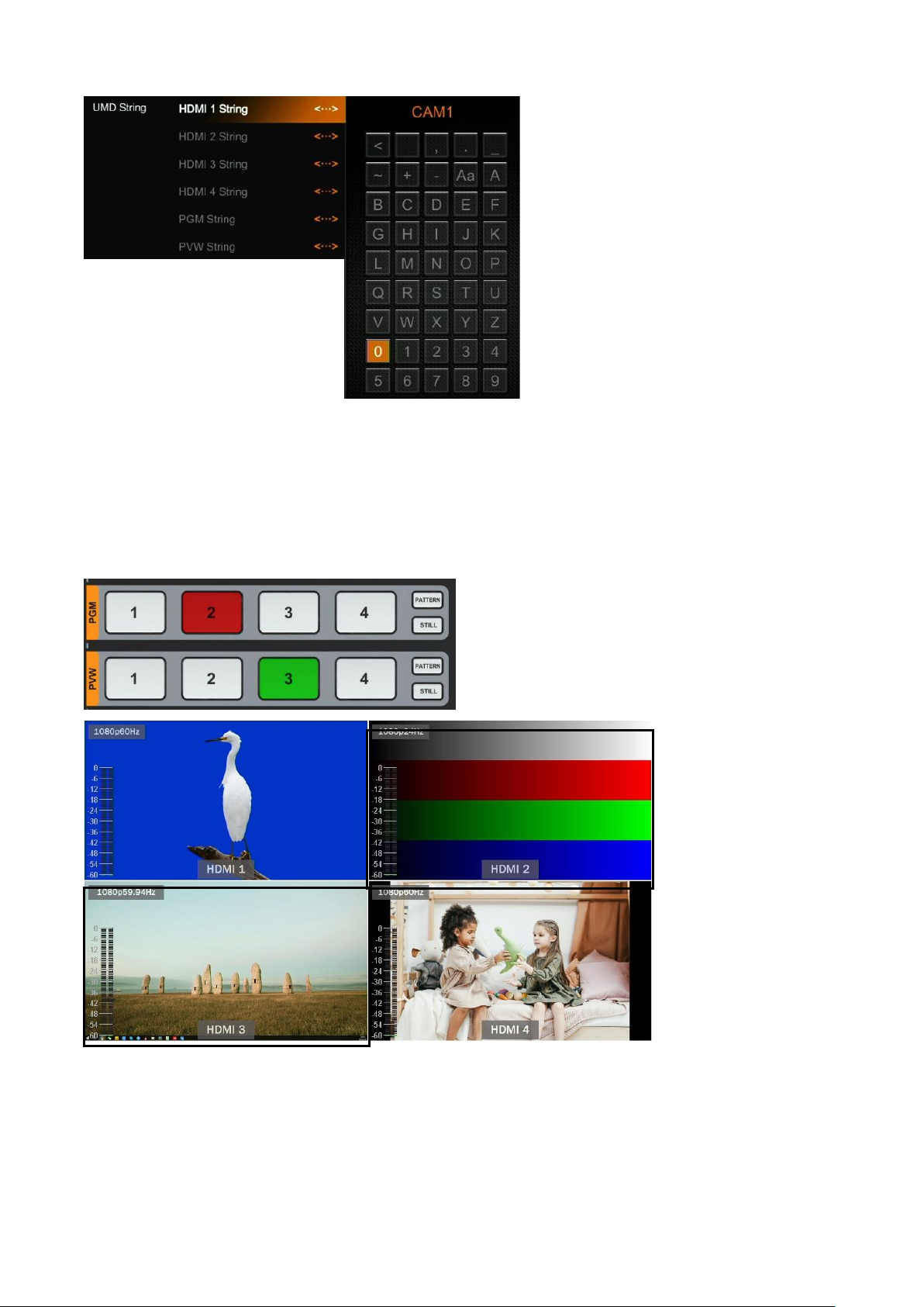
The default UMD of the four inputs are HDMI1, HDMI2, HDMI3, HDMI4. Users can turn on/off the UMD in
each window. Users can also set the overlay Opacity (50%, 75%, 100%), Size (Small/Medium/Large),
Position X & Y (1-100), Foreground color, and Background Color. See below image.
The UMD string content for the 4 HDMI inputs can be set from the menu. Users can rename the UMD
content for each window by using a virtual keyboard and rotary button. It supports a maximum of 10
characters for the UMD content. In the example below the input has been renamed from HDMI 1 to CAM1.
Page 14
10
7. PGM PVW SWITCHING
7.1. PGM PVW Channel Selection
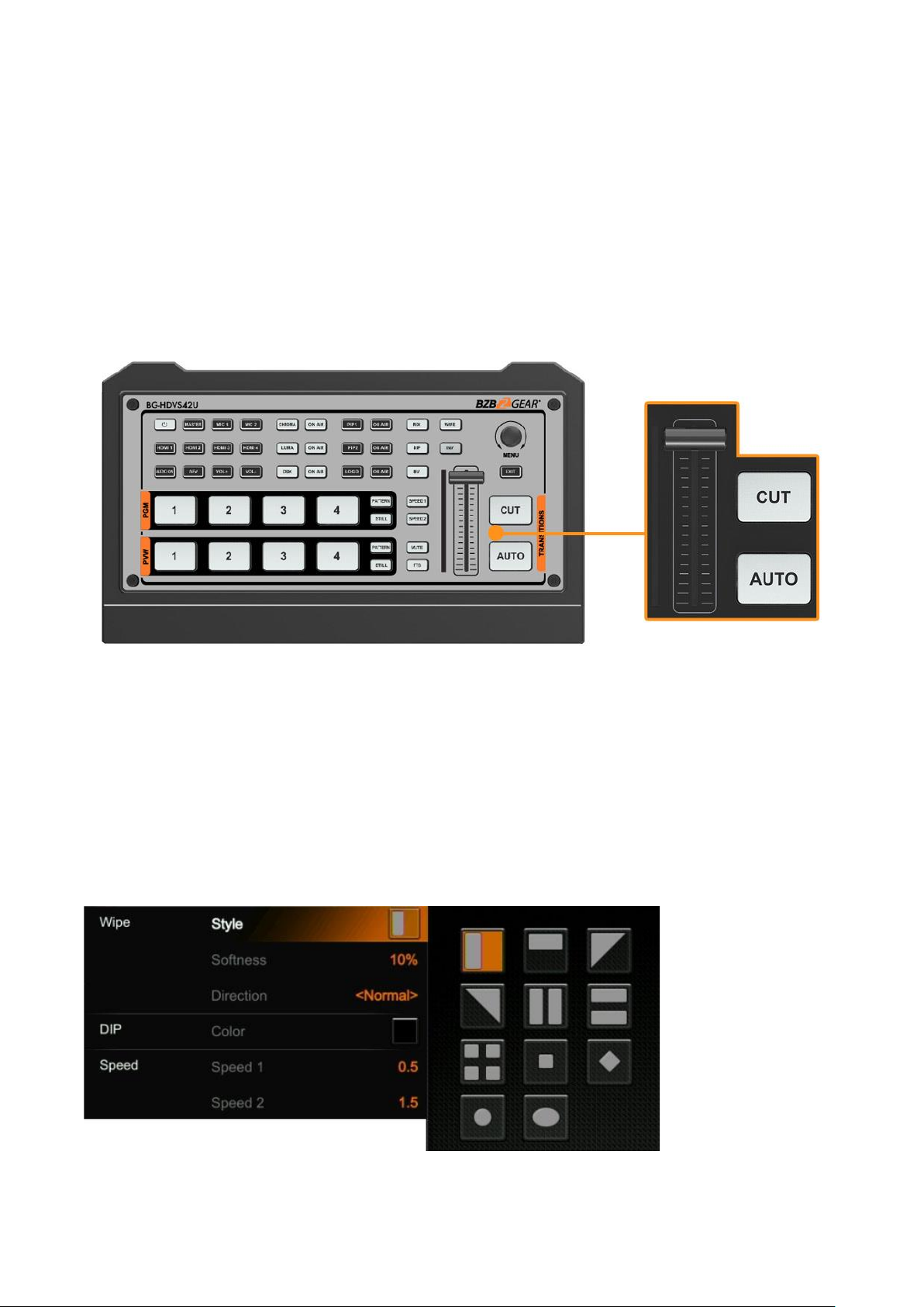
Choose the PGM and PVW sources from their corresponding row and enable/disable PATTERN
(different patterns can be configured in the menu, refer to Part 13.1) on the front panel. The selected
button for PGM will turn red and the selected button for PVW will turn green. The PGM source will be
highlighted with a red border, while the PVW source will be highlighted with a green border.
7.2. STILL
The video switcher features a STILL function which users can freeze the input sources. Select the
channel you want to freeze in the PGM or PVW row, then press the STILL button to freeze the input
source. Users can freeze all four inputs if desired. Press the input channel and STILL again to unfreeze
the image.
Page 15
11
7.3. Transition: CUT/ AUTO/ T-BAR
There are two transitional control types for this video switcher: Transition without effects (CUT) and
Transition with effects (AUTO, T-Bar).
CUT performs a simple immediate switch between Preview and Program. This is no delay providing
seamless switching, and the selected transition effect WIPE, MIX or DIP is not utilized.
AUTO performs an automated switch between Preview and Program views. The timing of the transition
can be set by speed button. The transition effects WIPE, DIP, MIX will also be used.
T-BAR manual transition is similar to using the AUTO button but offers flexibility as a manual transition
based on the speed that the user prefers using Hand Speed.
8. TRANSITION EFFECT
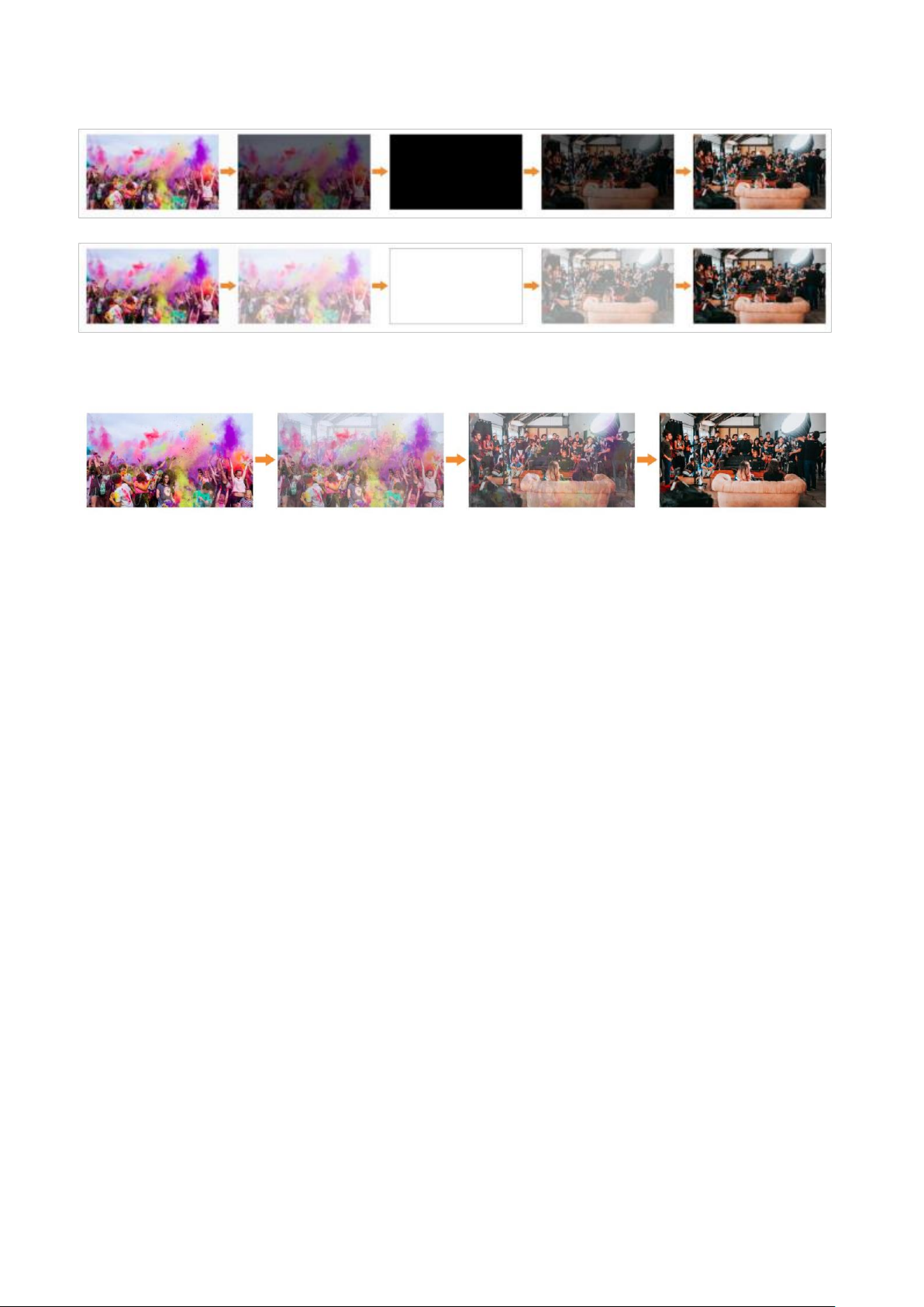
This switcher provides various transition effects including WIPE, DIP and MIX.
8.1. WIPE
Press the WIPE button to perform the wipe transition effect. Users can choose different versions of the
WIPE effect through the menu; as well as setting the softness of the edge. Select the direction from
Normal/ Invert/ Flip-Flop when using the AUTO transition feature.
Press the INV button to invert the selected wipe so it creates the reverse direction effect.
8.2. DIP
Press the DIP button to
perform the DIP
transition effect. User
can select from various
colors.
NOTE - On the menu screen, the default color is black.
Page 16
12
8.3. MIX
Press the MIX button to perform the MIX transition effect.
8.4. Transition Speed Setting
Users can set two speeds of transition on the menu, as well as define the speed value which can be saved
and will correspond to the Speed 1 or Speed 2 button. The higher value, the slower the transition speed,
selectable range is between 0.1s - 8.0s.
9. UPSTREAM KEY
9.1. Luma Key
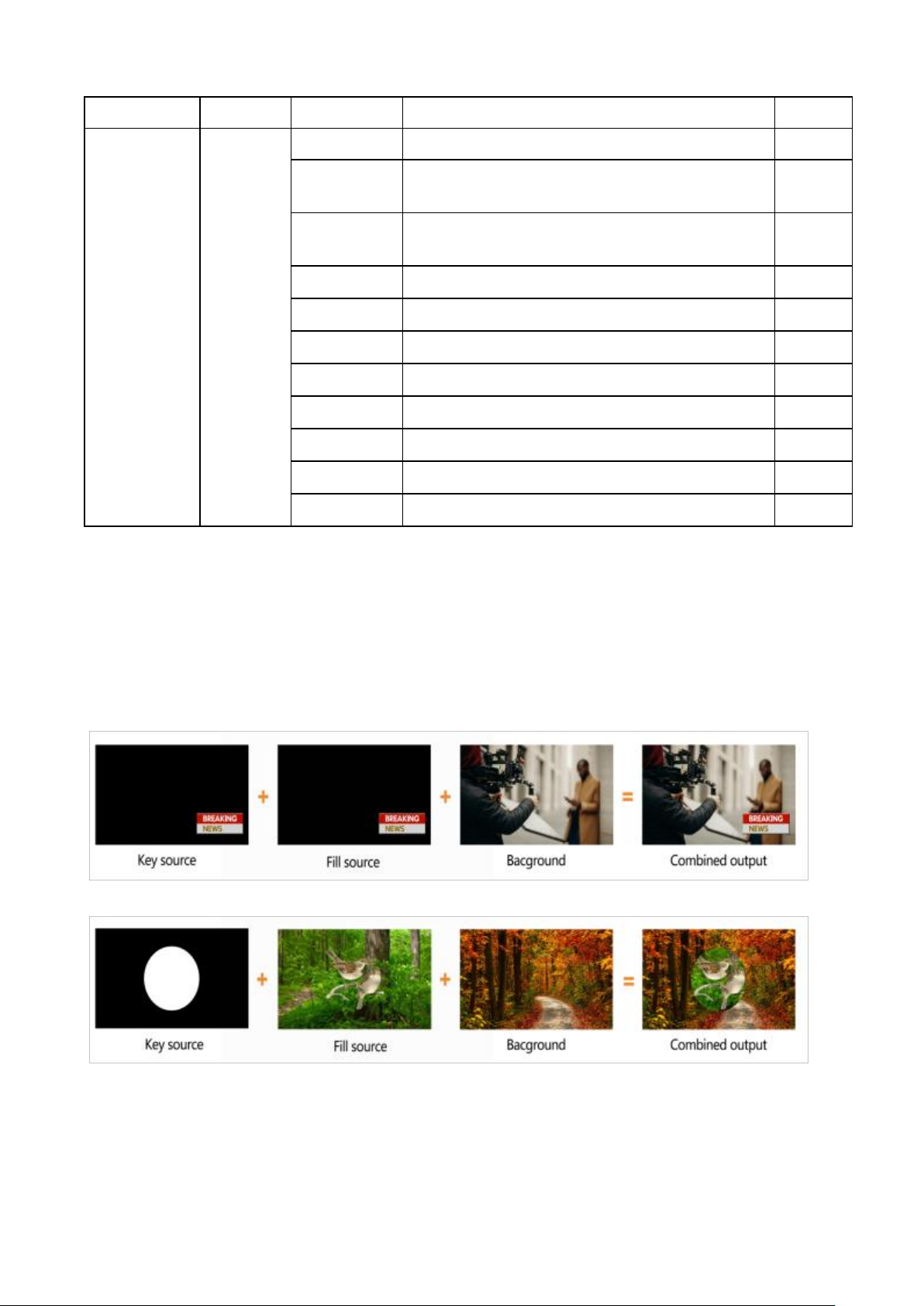
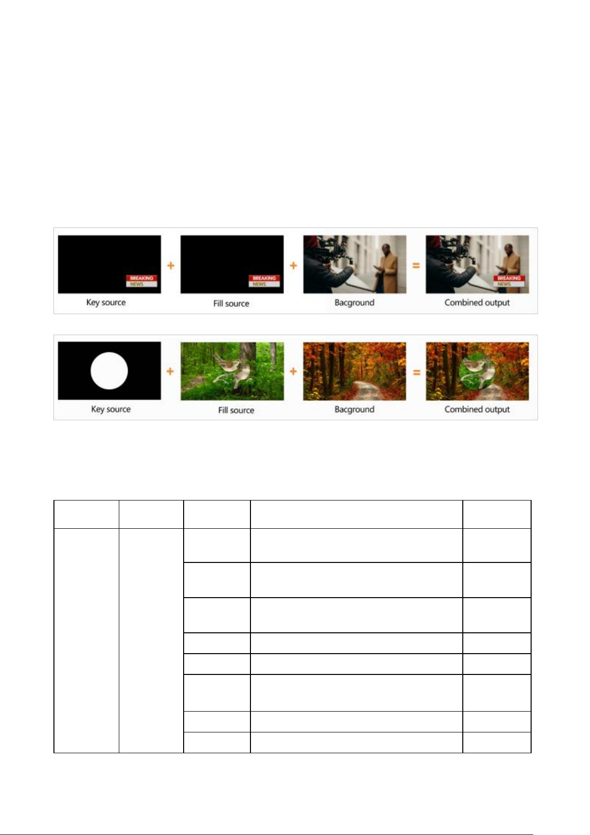
Luma keys provide a way to compose a foreground clip over a background clip based on the luminance
levels in the video. When the Luma Key is activated, a color from the key source will be removed,
revealing another background image behind it.
Switch the video with a background to the PVW window and turn on the Luma Key. Press the menu knob
to enter the settings menu. Users can assign the fill and key source from various options including
Black/ Color Bar/ Color1/ Color 2/ HDMI 1/ HDMI 2/ HDMI 3/ HDMI 4/ Image (import from USB disk).
Configure and adjust the Key parameters including Clip/Gain/Mask to achieve the desired effect. See
Key Menu Interface and Parameter settings below.
Press the ON AIR button and the ON AIR button will illuminate and LUMA button will turn off while the Key
effect will display on the PGM. Use CUT, AUTO, or T-Bar to switch the PVW with KEY to the PGM output.
LUMA button ON: Luma key shows on PVW
ON AIR button ON: Luma Key is available on PGM
ON AIR and LUMA button simultaneously ON: Luma Key is available on both PVW and PGM.
Corresponding status in menu is <KEY & ON AIR>
Page 17
13
Menu
Sub-Menu
Item
Parameter
Default
Upstream Key
Luma Key
Luma Status
OFF/ KEY (PVW)/ ON AIR (PGM)/ KEY & ON AIR
Off
Fill Source
Black/ Color Bar/ Color 1/ Color 2/ HDMI 1/ HDMI
2/ HDMI 3/ HDMI 4/ Image
Color1
Key Source
Black/ Color Bar/ Color 1/ Color 2/ HDMI 1/ HDMI
2/ HDMI 3/ HDMI 4/ Image
Image
Clip
0%-100%
10%
Gain
0%-100%
0%
Invert Key
On/Off
Off
Mask Enable
On/Off
Off
Mask Left
0%-100%
0%
Mask Top
0%-100%
0%
Mask Right
0%-100%
50%
Mask Bottom
0%-100%
50%
Clip: Adjust the threshold at which the key cuts its hole. When decreasing the clip more of the
background will appear. If the background video is completely black, then the clip value is too low.
Gain: Adjusts the performance of the chroma key in light or white areas. Apply more Key Gain if the light
areas are becoming too transparent.
Invert Key: Inverts the Key signal.
Mask: Configure the Mask for the Key area
Chroma key
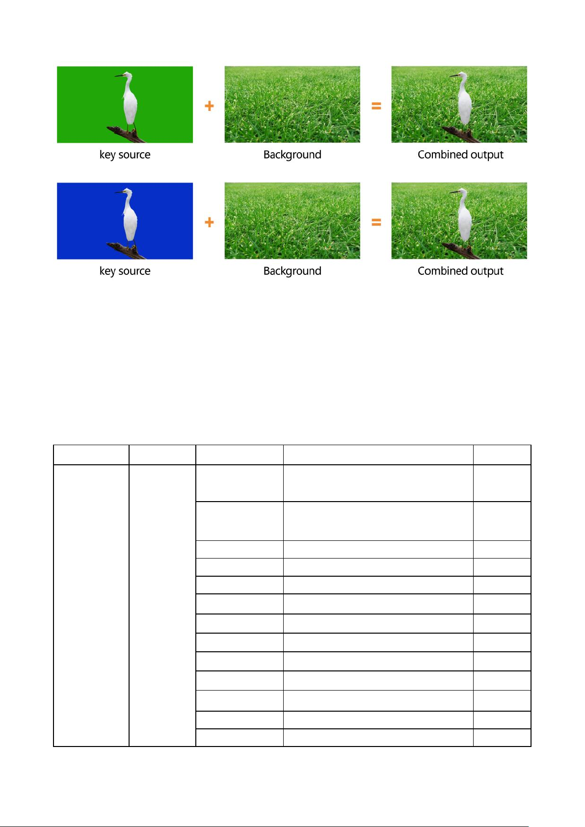
Chroma Key is a visual-effects and post-production technique for compositing (layering) two images or
video streams together based on color hues (chroma range). This technique is used in many fields to
remove a background from the subject of a photo or video, particularly the newscasting, motion picture,
and video game industries.
Page 18
14
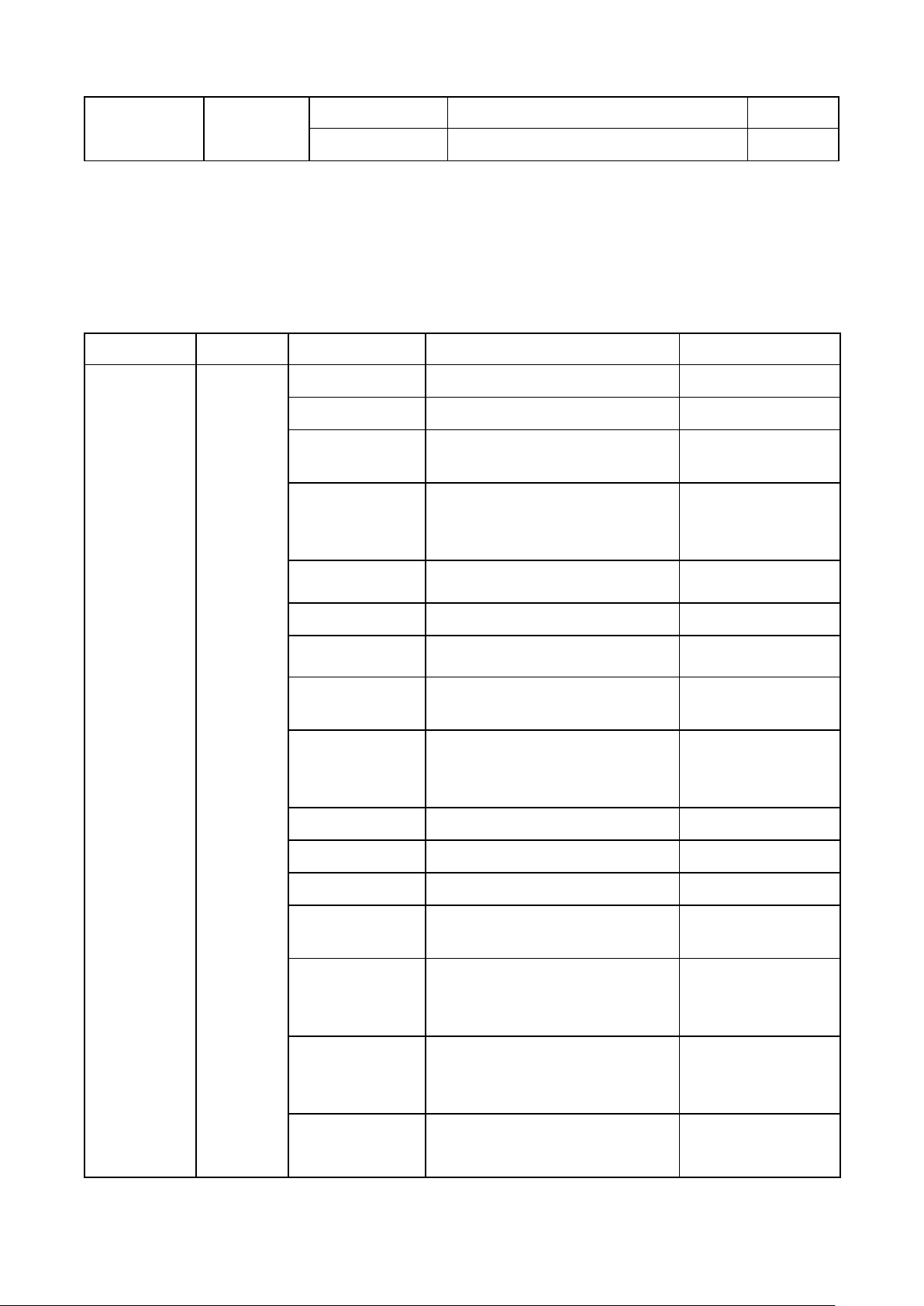
Press the CHROMA key button, press the Menu knob and choose Chroma to configure the effect of
Chroma Key, including the key source, Key color, Clip, Gain, Key Fetch and Mask, etc., detailed
parameters setting as below.
Press the ON AIR button next to the CHROMA button to enable the KEY on PVW. Use the AUTO key or
T-Bar control to switch the PVW with key to PGM.
CHROMA button ON: Chroma key shows on PVW.
ON AIR button ON: Chroma Key available on PGM
ON AIR and CHROMA button both ON: Chroma Key available on both PVW and PGM. Corresponding
status in menu is <KEY & ON AIR>
Menu
Sub-Menu
Item
Parameter
Default
Upstream Key
Chroma Key
Chroma Status
OFF/ KEY (PVW)/ ON AIR (PGM)/ KEY
& ON AIR
Off
Key Source
Black/ Color Bar/ Color 1/ Color 2/
HDMI 1/ HDMI 2/ HDMI 3/ HDMI 4/
Image
Image
Key Color R
0~255
10
Key Color G
0~255
154
Key Color B
0~255
56
Fetch X
0~100%
0
Fetch Y
0~100%
0
Fetch Width
0~50%
5
Clip
0%-100%
40%
Gain
0%-100%
10%
Mask Enable
On/Off
Off
Mask Left
0%-100%
0%
Mask Top
0%-100%
0%
Page 19
15
Mask Right
0%-100%
50%
Mask Bottom
0%-100%
50%
9.2. PIP & POP
The video switcher supports two groups PIP or one POP. When pressing PIP1 or PIP2 button, there will
be a small image display on the top left corner of PVW window. Press the Menu knob and choose the
PIP setting interface, user can set parameters including position, size, border, etc. See details below.
Press ON AIR button next to PIP1 and PIP2 to put the PIP into effect on PGM.
Set the POP in the same menu as detailed below. When POP is working PIP is disabled.
Menu
Sub-Menu
Item
Parameter
Default
Upstream Key
PIP/POP
Border Color
Color
White
Border Width
0~15
2
PIP1 Status
OFF/ KEY (PVW)/ ON AIR
(PGM)/ KEY & ON AIR
Off
PIP1 Source
Black/ Color Bar/ Color 1/ Color
2/ HDMI 1/ HDMI 2/ HDMI 3
/HDMI 4/ Image
HDMI 1
PIP1 Size
1/2 1/4 1/8
1/4
PIP1 Position X
0~100
0
PIP1 Position Y
0~100
0
PIP2 Status
OFF/ KEY (PVW)/ ON AIR
(PGM)/ KEY & ON AIR
Off
PIP2 Source
Black/ Color Bar/ Color 1/ Color
2/ HDMI 1/ HDMI 2/ HDMI 3
/HDMI 4/ Image
HDMI 2
PIP2 Size
1/2/1/4/1/8
1/4
PIP2 Position X
0~100
100
PIP2 Position Y
0~100
0
POP Status
OFF/ KEY (PVW)/ ON AIR
(PGM)/ KEY & ON AIR
off
POP Source 1
Black/ Color Bar/ Color 1/ Color
2/ HDMI 1/ HDMI 2/ HDMI 3
/HDMI 4/ Image
HDMI 1
POP Source 2
Black/ Color Bar/ Color 1/ Color
2/ HDMI 1/ HDMI 2/ HDMI 3
/HDMI 4/ Image
HDMI 2
Page 20
16
10. DOWNSTREAM KEY
10.1. DSK
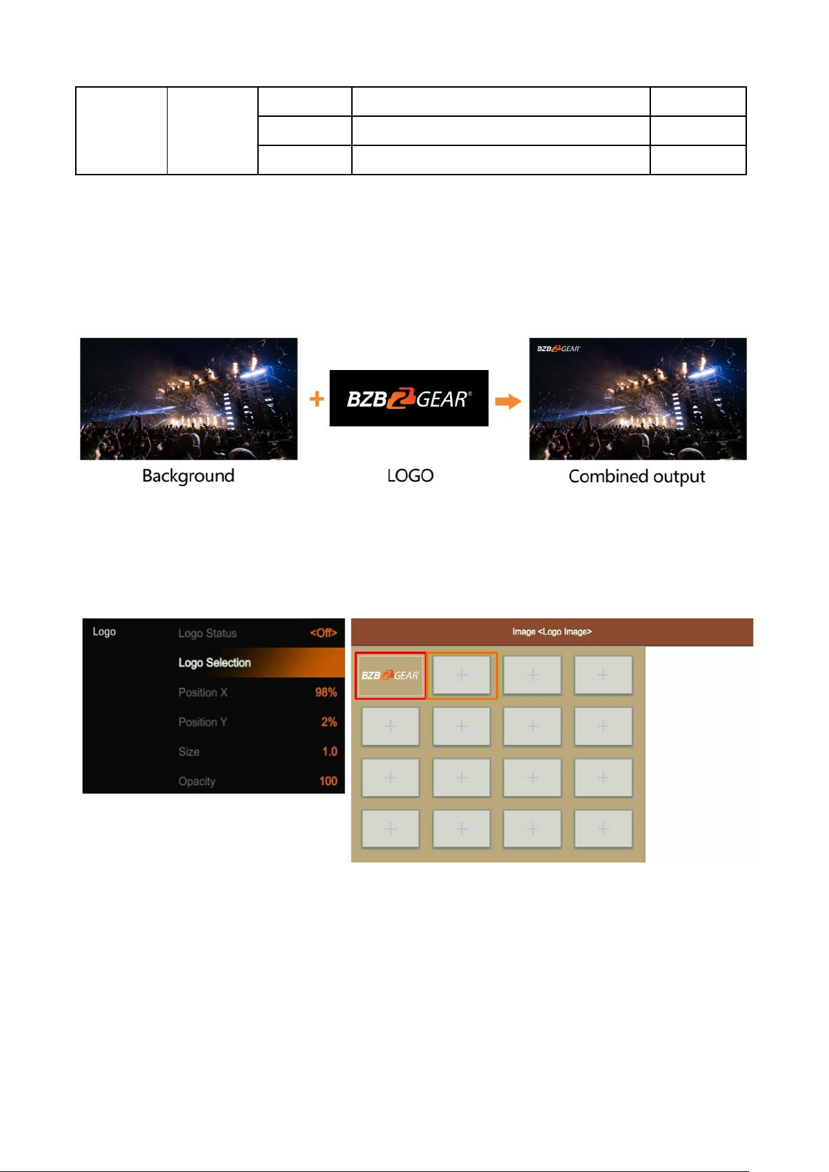
Press the DSK button to Mask the DSK signals utilizing the mask signal of the source. The source (Fill
Source, Key Source), Clip, Gain and mask (Mask Enable, Mask Left, Mask Top, Mask Right, Mask
Bottom) of DSK can be set from the menu. Options are detailed below. Press the ON AIR button next to
the DSK button to enable the KEY on PGM. Use the AUTO button or T-Bar control to switch the PVW
and DSK to PGM. The Key will not be changed when switching been the PVW and PGM.
DSK button ON: DSK key shows on PVW.
ON AIR button ON: DSK Key available on PGM.
ON AIR and DSK button both ON: Downstream Key available on both PVW and PGM. The corresponding
status in the menu is <KEY & ON AIR>
Menu
Sub-Menu
Item
Parameter
Default
Downstream
Key
DSK
DSK Status
OFF/ KEY (PVW)/ ON AIR (PGM)/ KEY &
ON AIR
Off
Fill Source
Black/ Color Bar/ Color 1/ Color 2/ HDMI 1/
HDMI 2/ HDMI 3 /HDMI 4/ Image
Black
Key Source
Black/ Color Bar/ Color 1/ Color 2/ HDMI 1/
HDMI 2/ HDMI 3 /HDMI 4/ Image
Black
Clip
0%-100%
0%
Gain
0%-100%
0%
Invert Key
On/Off
Off
Mask Enable
On/Off
Off
Mask Left
0%-100%
0
Page 21
17
Mask Top
0%-100%
0
Mask Right
0%-100%
0
Mask Bottom
0%-100%
0
10.2. LOGO
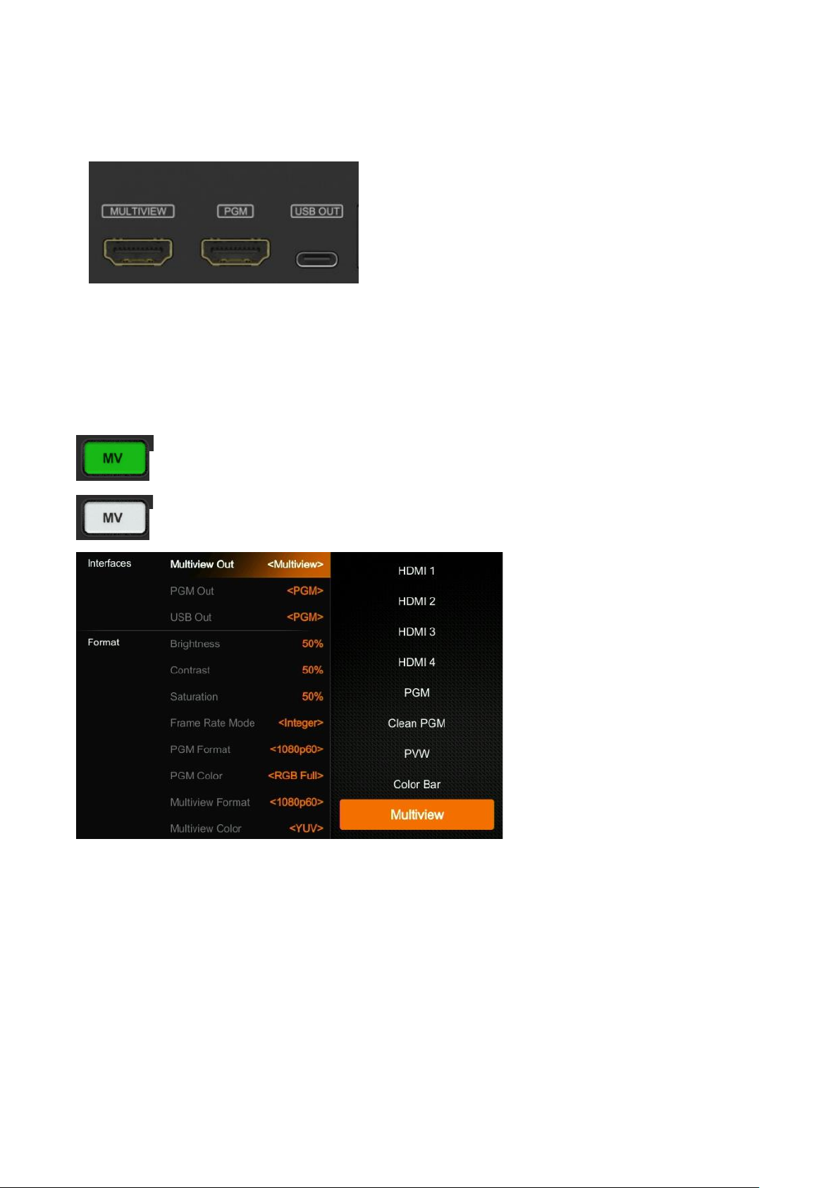
This switcher permits users to import logos. Press the menu knob and choose the logo setting interface, this is
where the user can choose a logo from the media pool on the USB disk and set the position, size, and opacity.
Rotate the menu knob to choose the logo, press the Menu knob to select and delete a logo. Users can view the logo
effect in PVW.
Press the ON AIR button next to LOGO button to display the effect.
LOGO button ON: DSK key shows on PVW.
ON AIR button ON: DSK Key available on PGM
ON AIR and LOGO button both ON: LOGO available on both PVW and PGM. Corresponding status in
menu is <KEY & ON AIR>
Page 22
18
11. OUTPUT SETTING
11.1. Output Interfaces
The HDVS42U has 3 output interfaces, Multiview Out, PGM
Out and USB-C Out. The 3 outputs can also be assigned as
AUX OUT for HDMI1, HDMI2, HDMI3, HDMI4, PVW, PGM,
Clean PGM, Color Bar and Multiview out.
11.2. Multiview Out
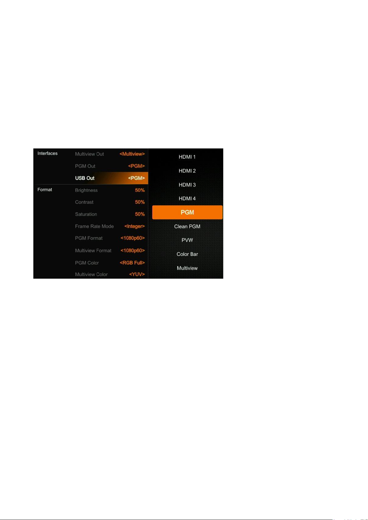
The default output of the Multiview port is the Multiview window, the LED indicator of MV button on the
front panel is green to indicate default status. Users can connect it to an additional LCD display to view
the 4 HDMI source inputs using PVW, PGM and status interface. Users can also configure the output of
the Multiview port for other options based on an application’s requirements. When the Multiview output is
defined as an alternative output, for example HDMI 1, the user can press the MV button to switch inputs
for the Multiview output to the configured HDMI 1.
11.3. PGM Out
When designating specific outputs for the PGM output, the user can connect it to an additional LCD display
to monitor the PGM out video. The PGM output video is the Program video including the overlay images
from USK and DSK. PGM Clean out is the option for removing the overlay images from Program out DSK.
11.4. USB Out
Connect the USB-C output to a PC with a USB2.0 cable for software programs like OBS Studios,
PotPlayer, vMix, etc. Play or store the captured USB streaming video and audio on live streaming platforms
like YouTube, Facebook, Twitter, etc. The USB2.0 streaming output is based on UVC (USB video class)
: LED indicator on, Multiview output port shows the Multiview.
: LED indicator off, Multiview output port shows the configured alternate output.
Page 23
19
and UAC (USB audio class) standards. No additional drivers need to be installed.
The video source of USB for the PGM output can be associated with HDMI1, HDMI2, HDMI3, HDMI4,
PVW or the Clean PGM output. This means users can capture any input source for live streaming
capabilities.
Upon completing the connection, the relevant video and audio devices will be added in the Windows
Device Manager as below:
• Under Imaging Devices: USB2.0 Capture Video
• Under Audio inputs and outputs: USB2.0 Capture Audio
11.5. Output Format Setting
11.5.1. PGM Image Setting
Users can set Brightness, Contrast, and Saturation of the PGM output in the menu. The setting range is
from 0%-100%. The default setting is 50%.
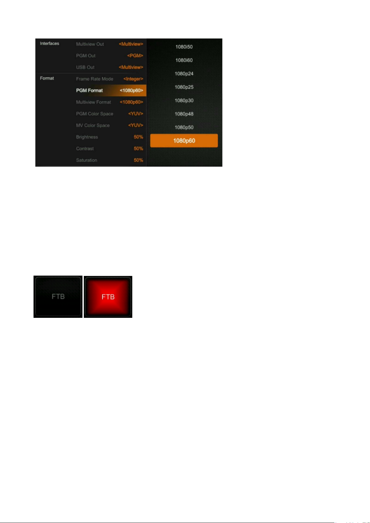
11.5.2. PGM and Multiview Format
The switcher supports up/ down scaling output. Users can switch the Frame Rate Mode between Integer
or Decimal. When the Frame Rate Mode is integer, available options are 1080i50, 1080i60, 1080p24,
1080p25, 1080p30, 1080p48, 1080p50, 1080p60. When the Frame Rate Mode is set to Decimal available
options are 1080i50, 1080i59.94, 1080p23.98, 1080p25, 1080p29.97, 1080p47.95, 1080p50, 1080p59.94.
The default format of the PGM and Multiview outputs are 1080p60.
Page 24
20
11.5.3. PGM and Multiview Color Space
There are YUV, RGB Full, RGB Limit color space options for PGM and Multiview out. The default color
space of the output is YUV.
11.6. FTB
The FTB (Fade to black) feature is usually for an emergency situation when using the switcher for a live
event. By pressing the FTB button the PGM will fade to a black screen to hide all the other layers, and the
FTB button will keep flashing until user press the button again to stop the FTB.
Note: When the PGM window displays black for an extended period of time (5-10 seconds) even after the
transition, verify that the FTB button is flashing.
(1) Set the FTB and Mute speed
The speed of FTB / MUTE is adjustable from 0-3s located in the menu. The speed relates to the time
regarding the entire transition for FTB and MUTE. For example, if the speed is set to 2.5s the PGM video
will be fading to black with audio gradually becoming muted in 2.5s.
(2) FTB with MUTE
FTB can also work with MUTE. Press the MUTE button or turn on the FTB with MUTE on from the menu,
then the PGM will be faded to black with mute active.
Page 25
21
12. AUDIO SETTING
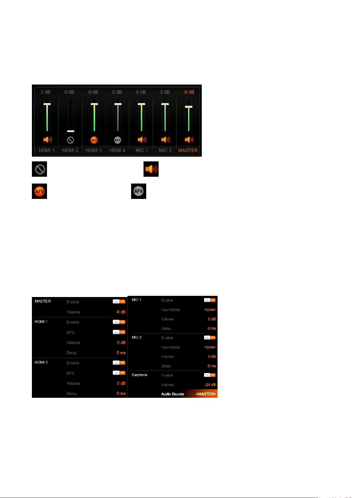
All audio statuses are displayed in the status page of Multiview, and in each Multiview window there is an
audio meter for monitoring status of all the audio inputs.
=Audio off; =Audio on, AFV off;
=Audio on, AFV on & activated; =Audio on, AFV on & nonactivated.
12.1. Master Audio
Master audio is the primary audio control for the PGM output. It can be mixed audio or AFV audio. Users
can turn on/off the master audio or adjust audio volume.
12.2. Audio On (MIX)
There are 6 Audio source inputs that can be selected for the audio source embedding, including 4 HDMI
connections and 2 MIC 3.5mm audio inputs. Users can turn on/off or adjust volume for each audio of HDMI
1, HDMI 2, HDMI 3, HDMI 4, MIC 1 and MIC 2 independently. When enabling an audio source the audio
will be permanently mixed into the PGM output.
12.3. AFV
Each channel of the 4 HDMI embedded audio inputs can be set to AFV (Audio-Follows-Video). When one
HDMI embedded audio is set to AFV, then the audio will be turned on when the PGM switches to the HDMI
video. See the below image as an example. When HDMI 1 embedded audio is set to AFV, the HDMI 2
embedded audio will be turned off when selecting HDMI1 for audio aligning with video source for PGM.
Page 26
22
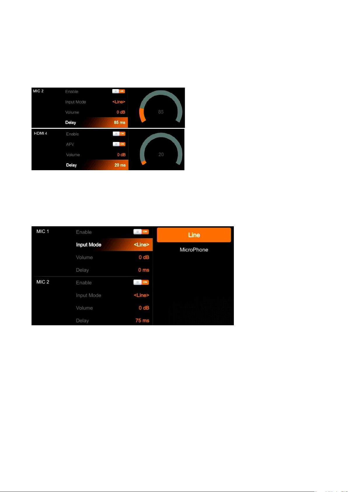
12.4. Audio Delay
In the menu there is an audio delay setting for HDMI 1, HDMI 2, HDMI 3, HDMI 4, MIC 1 and MIC 2. Users
can adjust the audio delay to make the audio and video synchronization. One level of the audio delay
setting equal 5ms. The audio can be delayed max 500ms.
12.5. MIC
The switcher has two MIC inputs that users can connect to a line-level or microphone signal and turn
on/off or adjust the audio volume and delay level.
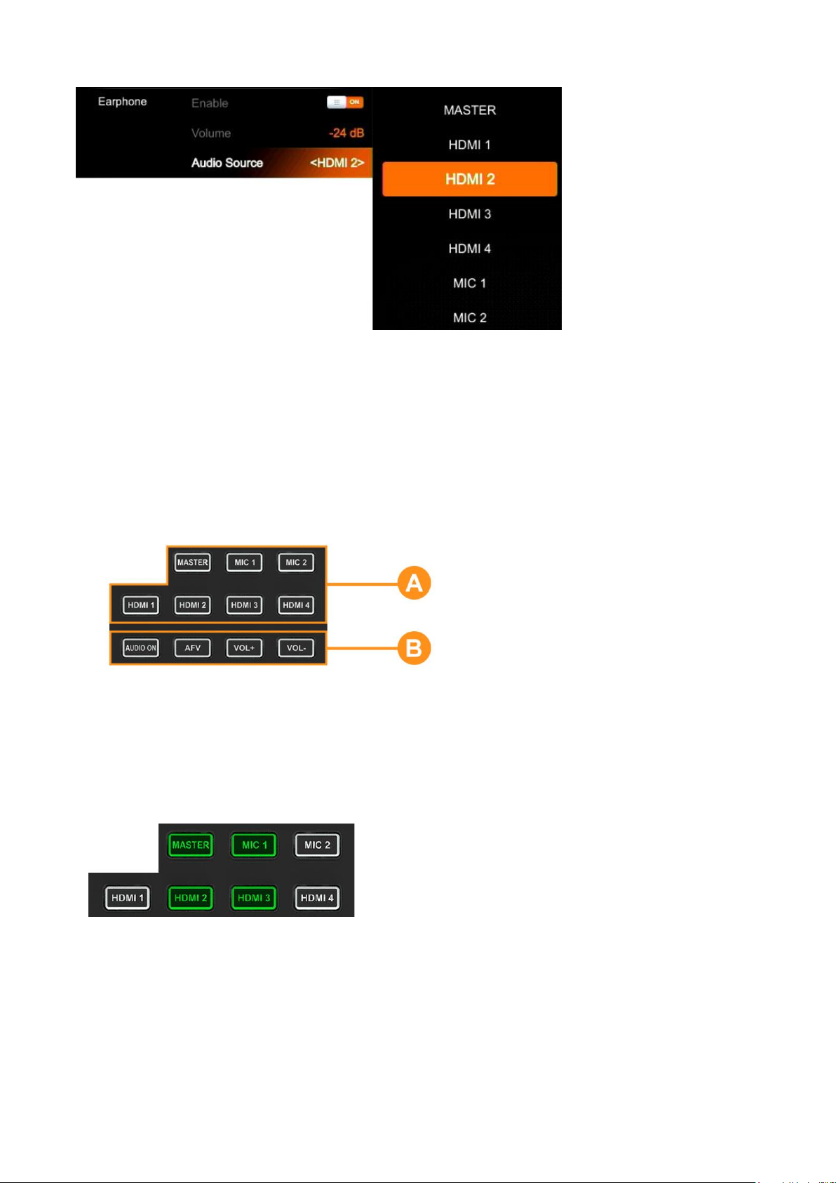
12.6. Headphone
The switcher has a headphone output for monitoring audio. Users can choose one audio source for
headphone from Master audio, 4 embedded HDMI audio sources, and 2 MIC inputs. Users can turn
on/off the headphone or adjust audio volume.
Page 27
23
12.7. Audio Keyboard Configuration
The audio not only can be configured in the menu, but it can also be configured using the keyboard
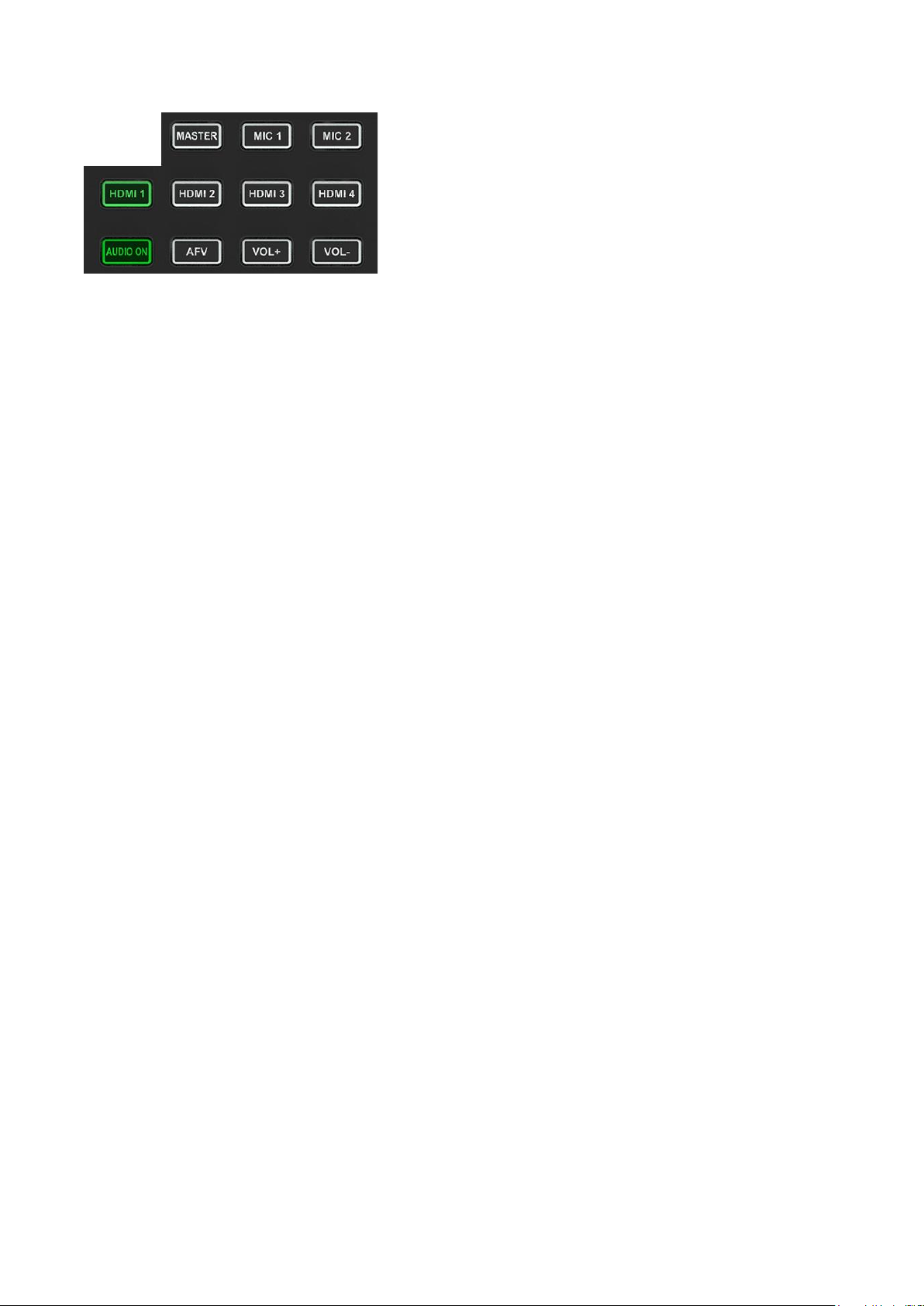
control of the switcher. The keyboard includes two parts as below image.
Part A is for selecting one audio to be
configurated, including Master, MIC 1, MIC 2,
HDMI 1, HDMI 2, HDMI 3 and HDMI 4.
Part B is for setting audio functions, including
AUDIO ON, AFV, VOL+ and VOL-.
12.7.1. Audio Indicator
The LED indicator of buttons shows the current audio status.
When the indicator button in Part-A is green, it indicates the
corresponding audio is ON. When the indicator is OFF it
means the corresponding audio is OFF.
In the example image, when the indicators of MASTER,
MIC 1, HDMI 2, HDMI 3 are on, the corresponding audio
sources are ON. The indicators of MIC 2, HDMI 1, HDMI 4 are off, the corresponding audio signals are
OFF.
Page 28
24
When any button in Part-A is pressed and the indicator for the
button in Part B turns green it means the corresponding audio
function is ON. When the indicator is OFF it means the
corresponding function is OFF.
In the example image, after pressing the HDMI 1 button, the
indicator for HDMI continues flashing. If the AUDIO ON
indicator button is green and the indicator of AFV button is
OFF, this indicates the audio of HDMI 1 is ON and the AFV of HDMI 1 is OFF.
12.7.2. Audio Configuration Steps
Step 1. Press any button from Part-A to select the audio for configuration, the LED indicator of the button
will continue flashing which indicates it is available to configure.
Step 2. Press the AUDIO ON button from Part-B to turn on the audio. The LED indicator will turn green.
Press the AFV button to set the audio following video, and the LED indicator will turn green. Double-tap
the AUDIO ON/ AFV button to turn it OFF and the indicator will also turn off. Press the VOL+/ VOLbuttons to adjust the audio volume.
Note: AFV button is not available for MASTER.
Step 3. The selected button from Part-A in Step 1 is still flashing, press it again to finish the configuration
and the indicator should stop flashing. Alternatively, when the Part-A button is flashing press another
button from Part-A to select the next audio source for configuring. When audio configuration is complete,
press the flashing button again from Part-A to complete configuration and stop the flashing indication.
12.8. Mute
The switcher has a MUTE button in the row of PVW keyboard. It is quick and easy for users to press the
button to make the Master audio turn off. When MUTE turns on the LED indicator keeps flashing which
means the PGM audio is being muted. The speed of MUTE can be set from menu (Refer to Part 12.8)
Page 29
25
13. MEDIA LIBRARY
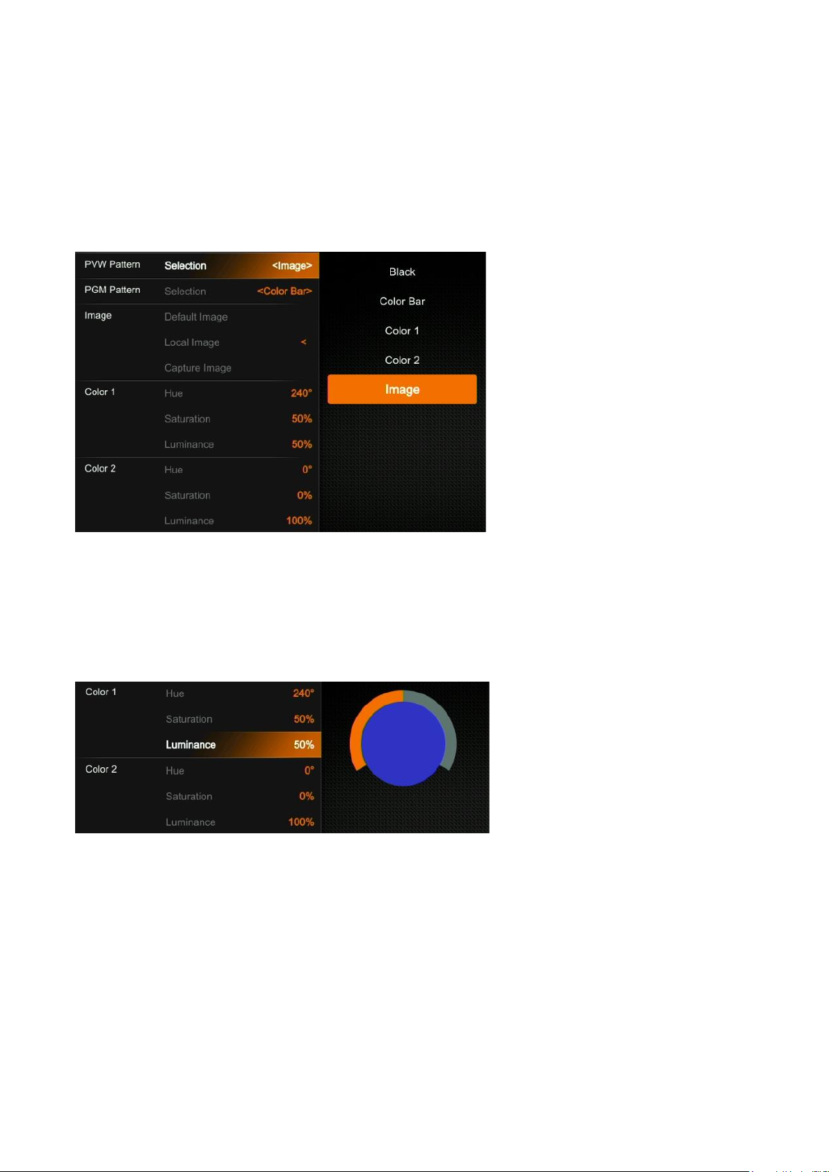
13.1. PVW Pattern & PGM Pattern
The switcher can generate patterns for PVW and PGM. The PVW/PGM pattern source can be selected
from the Color Bar, Black, Color 1, Color 2 and Image.
13.2. User-defined Color Pattern
There are two color patterns Color 1 and Color 2 for user-definition. Users can set the hue, saturation, and
luminance to generate the color pattern for Color 1 and Color 2. See below image.
13.3. Image Setting
The Image is one of the sources for PVW Pattern and PGM Pattern. Users can choose the Image source
from the Default Image, Local Image or Captured Image. The selected image is the last selection from the
Default image, Local Image, and Capture Image.
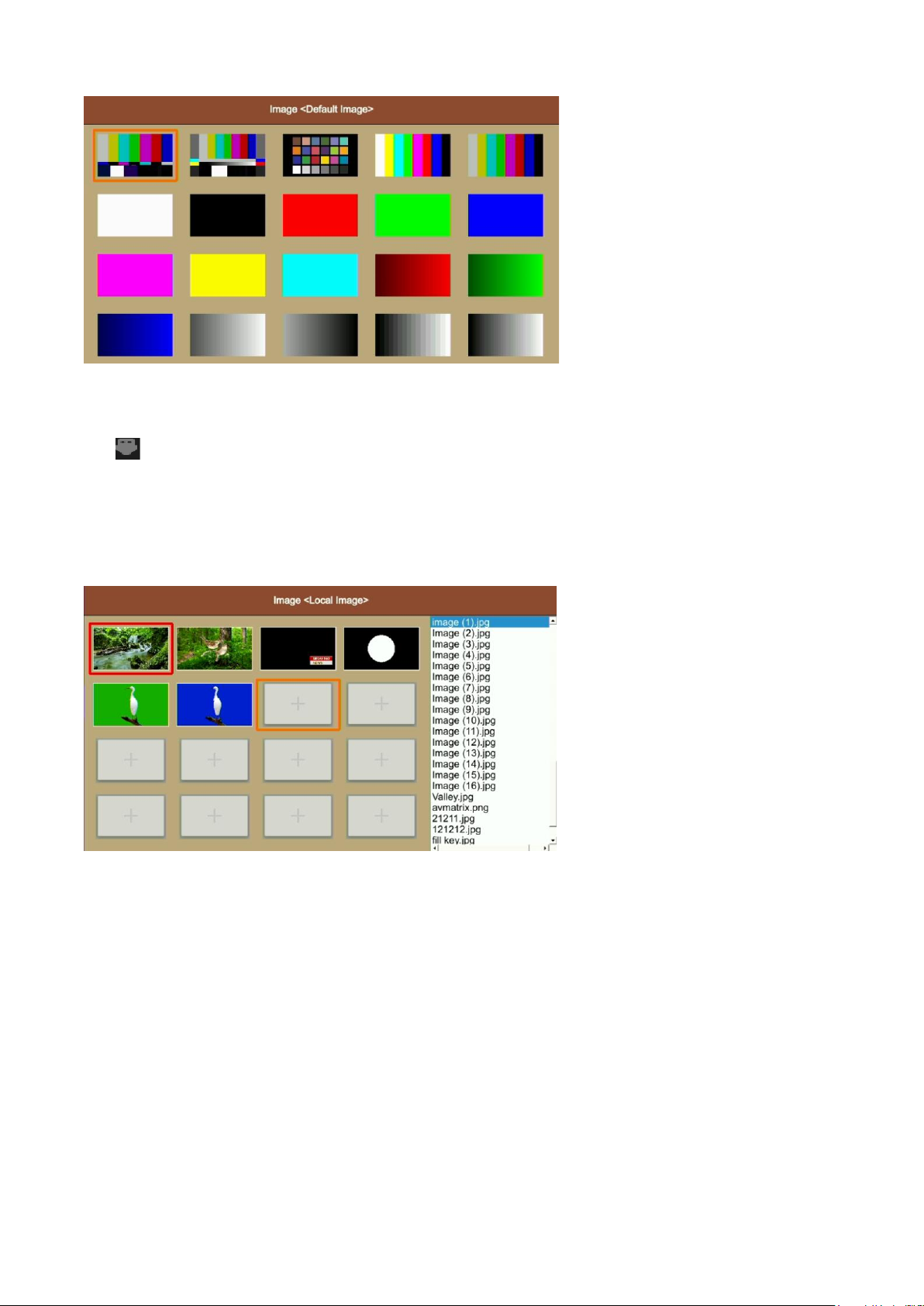
13.3.1. Default Image
The default images are preset in the switcher. Use the rotary button to select one of images from the
Default Image as the source for PVW or PGM pattern.
Page 30
26
13.3.2. Local Image
The local images are the images which you upload from USB disk. When you plug in a USB drive, a USB
icon will appear in the bottom of the Status/Menu page. The image list from USB disk displays on the
right side of the menu. Select a single image to upload it into the switcher. The uploaded image will be
listed in the media list. Users can press the rotary button to select the uploaded image as source for
PVW/PGM pattern by selecting the option Select. Users can delete the uploaded image from the menu.
See below images.
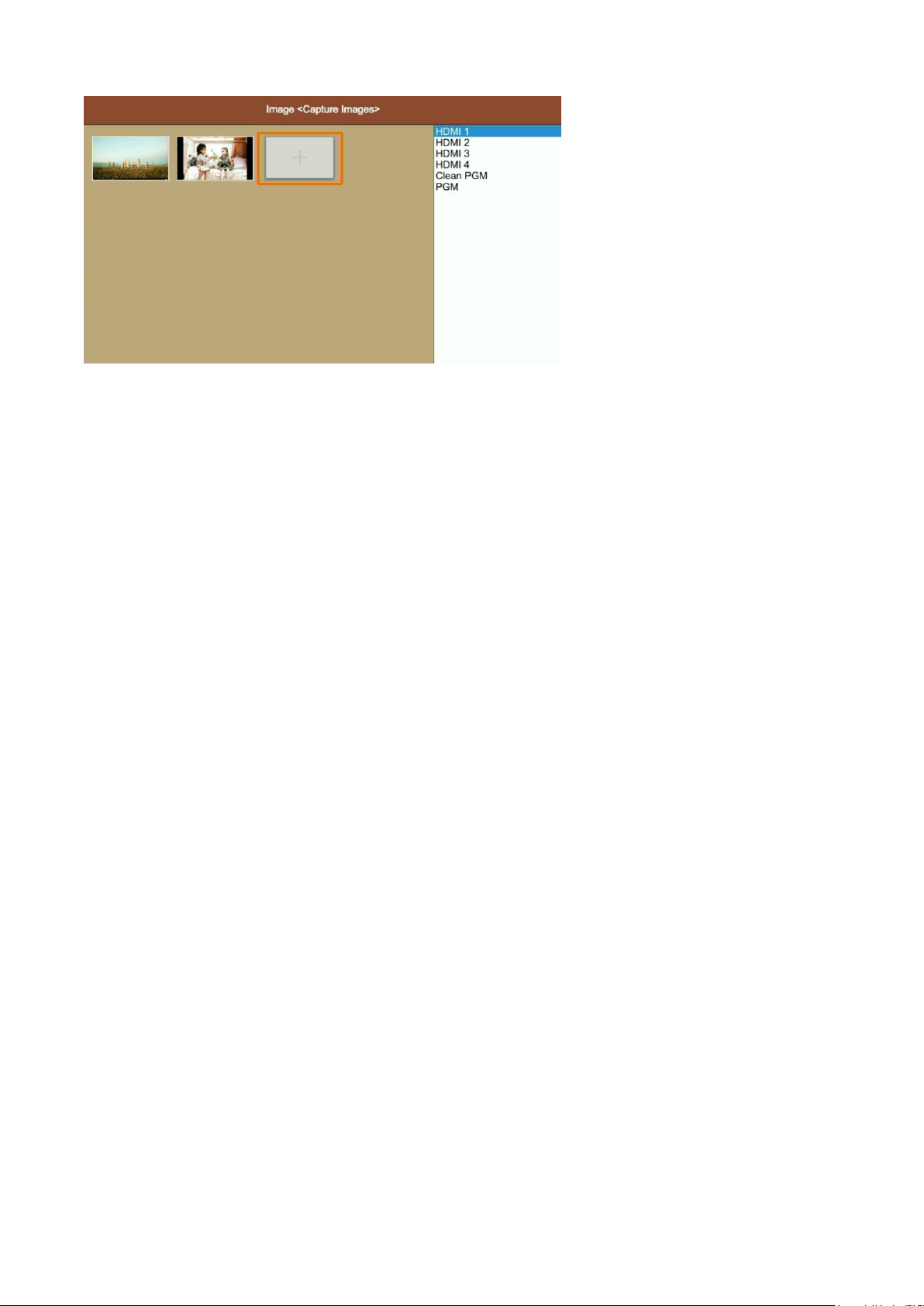
13.3.3. Capture Image
The capture image comes from a screenshot of HDMI 1, HDMI 2, HDMI3, HDMI 4, Clean PGM, PGM. The
captured image will be listed in the media list. Users can press the rotary button to select the captured
image as source for PVW/PGM pattern by selecting the option Select. Users can delete the captured
image from the menu. See below images.
Page 31
27
14. SYSTEM SETTING
14.1. Language
Entering system settings from the menu to switch the system language between English and Chinese.
14.2. Fan Setting
Setting the cooling fan speed to control the temperature and noise of the switcher. There are 3 options,
Auto/ Off / On.
When users select the Auto option, the speed of the fan will be adjusted automatically according to the
switcher’s operating temperature. If the application/environment requires no fan noise, the user can turn
the fan off manually from the menu as well if the switcher’s operating temperature continues to elevate
and reaches the preset value, a pop-up prompt notification will appear and auto turn on the high-speed
fan cooling down the CPU. If the switcher is working in a high temperature environment and the auto fan
setting is unable to meet required cooling temperature, then the user can select the fan setting to ON
option to maintain the high-speed fan setting.
14.3. System Reset
- Reset Preferences: Restore settings to default Settings but remain the part of settings including the Media
library, Time, Network, Language, Fan and User Setting.
- Factory Reset: Restore all settings to default Factory Settings.
14.4. Download
The BG-HDVS42U comes with a free PC control software. Users can connect the switcher with a windows
OS computer via LAN port to have remote control. The software and user manual can be downloaded from
www.bzbgear.com.
14.5. Version
Check the switcher’s Software Version, FPGA Version, MCU Version, PCB Version.
14.6. Time Setting
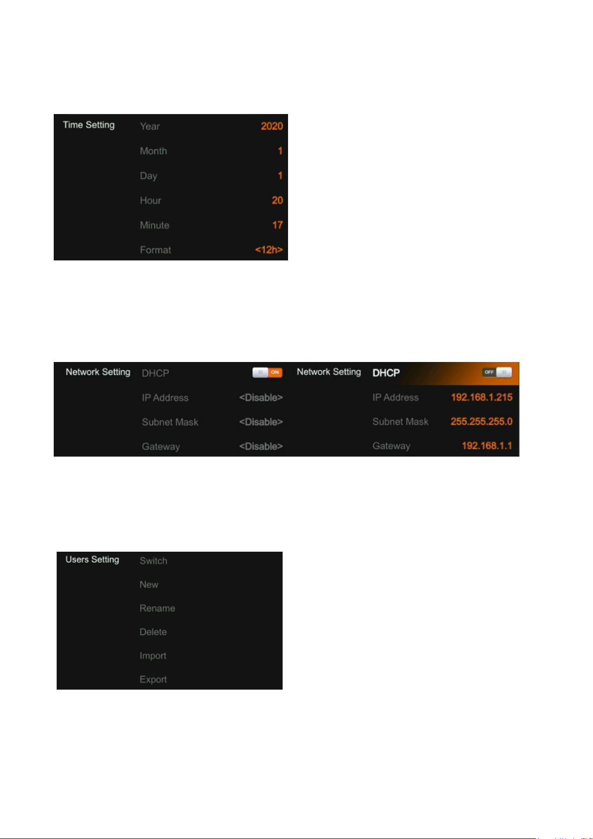
14.6.1. Setting Time Manually
Users can set Year/ Month/ Day/ Hour/ Minute directly through the Menu. The time format can be set to12h
and 12h. The default setting is 12h.
Page 32
28
14.6.2. Time Synchronization
Connect the video switcher to a PC (windows OS) via LAN port and use the control software to search for
the device. The time will automatically synchronize once the video switcher is discovered on the network.
14.7. Network Setting
There is a switch setting for DHCP in the menu. When turning on DHCP, the switcher will obtain an IP
address automatically after connecting the switcher to the network using DHCP.
When turning off DHCP, users can set the IP address, Subnet Mask, Gateway from menu manually. The
default IP address of the switcher is 192.168.1.215.
14.8. User Setting
Users can save all current settings into an account in the switcher. Adding a new user account, renaming
the account, switching between accounts, deleting the account or even user can import or export the
account to a USB flash disk.
14.8.1. New
Adding a new user account and save all current settings to the account. Input the name through a virtual
keyboard from the menu.
Page 33

29
14.8.2. Rename
Rename the current user account name.
14.8.3. Switch
Switch to another saved user account to have the saved settings easily and quickly. Meanwhile, the
Username will be updated in the bottom of the Status/Menu page after switching.
14.8.4. Delete
Delete a saved user account which you will never use again.
14.8.5. Import
Import the current user account and settings to USB flash disk.
14.8.6. Export
Export the user account and settings saved in USB flash disk.
Page 34

30
Warranty
BZBGEAR wants to assure you peace of mind. All BZBGEAR cameras and camera-related products
include our Stress-Free Three-Year Warranty.
For complete warranty information, please visit BZBGEAR.com/warranty.
For questions, please call 1.888.499.9906 or email [email protected].
Mission Statement
BZBGEAR manifests from the competitive nature of the audiovisual industry to innovate while keeping the
customer in mind. AV solutions can cost a pretty penny, and new technology only adds to it. We believe
everyone deserves to see, hear, and feel the advancements made in today’s AV world without having to
break the bank. BZBGEAR is the solution for small to medium-sized applications requiring the latest
professional products in AV.
We live in a DIY era where resources are abundant on the internet. With that in mind, our team offers
system design consultation and expert tech support seven days a week for the products in our BZBGEAR
catalog. You’ll notice comparably lower prices with BZBGEAR solutions, but the quality of the products is
on par with the top brands in the industry. The unparalleled support from our team is our way of showing
we care for every one of our customers. Whether you’re an integrator, home theater enthusiast, or a do-ityourselfer, BZBGEAR offers the solutions to allow you to focus on your project and not your budget.
 Loading...