

Page 1
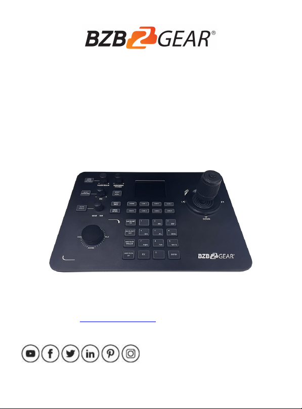
BG-Commander
PTZ Camera Controller
User Manual
CONTACT
FOLLOW US
Page 2

Thank You!
Thank you for purchasing the BG-Commander IP/Serial PTZ joystick controller. This manual will help
you familiarize yourself with the capabilities and functions of this device. Before setting this device up
it is recommended that you read this manual in its entirety to ensure optimal performance. This
product has been designed for years of trouble-free use. To keep this product functioning optimally
please follow these recommended guidelines for care and maintenance.
Precautions
• Never expose the controller to moisture.
• Do not drop the controller.
• Clean only with a soft dry microfiber cloth.
• Connect controller with only PoE or the included power supply.
• Do not disassemble the unit in any way to avoid risk of electrical shock or damage.
There are no user serviceable parts, and this will void your product warranty.
• Only use within the recommended temperature and humidity parameters
1.Product Description
1.1 Overview
The BG-Commander is designed to provide precise control of BZBGEAR’s complete line of
cameras with support for both IP and serial control protocols. It supports VISCA over IP and
ONVIF protocols as well as VISCA, Pelco-D, and Pelco-P via RS-232/422/485. The web
interface makes it easy to quickly add IP cameras.
o Operating temperature range: 14° - 122°F (-10° - 50°C)
o Operating humidity range: 10 – 90%
-01-
Page 3
-02-
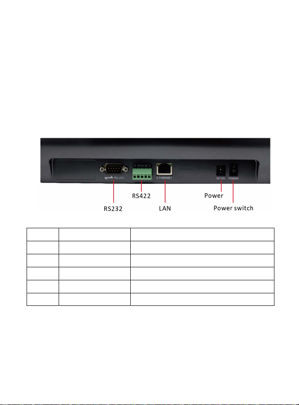
1.2 Product Features
Number
Name
Function
1
Power switch
Power on/off
2
Power
Stand ard 5.5/2.1 power port, DC 1 2V2A±10%
3
LAN
Network Connection
4
RS232
Supports Visca, Pelco-P/D
5
RS422
Supports Visca, Pelco-P/D
• Supports IP and analog control modes
• Supports VISCA over IP, ONVIF, Pelco-P/D, and VISCA protocols
• Variable speeds for all control axes
• Zoom can be controlled by twisting the control handle or the dedicated zoom knob
• Integrated browser interface for quick setup
• Supports PoE
1.3 Interface Description
Page 4
-03-
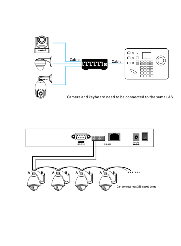
1.4 System connection diagram
(1) Network connection
video
conference
camera
Dome
camera
PTZ
Camera
(2) RS485 connection diagram.
Control output:
The RS485+ of the camera is connected to Ta of the controller, and the RS485- of the camera
is connected to the Tb of the controller.
Page 5
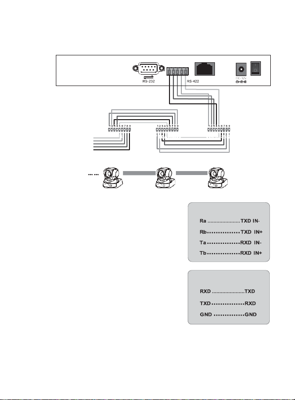
(3) RS 422 connection diagram
Controller
Camera
Controller
Camera
VISCA RS422
VISCA RS422
VISCA RS422
*7 cameras max
When using RS422 bus connection mode, the third
pin (Ra) of the controller is connected to the TXD
IN- of the camera, the fourth pin (Rb) of the
controller is connected to the TXD IN+ of the
camera, the first pin (Ta) of the controller is
connected to the RXD IN- of the camera, and the
second pin (Tb) of the controller is connected to
the RXD IN+
Using RS232 connection mode, the first pin (RXD) of
the controller (10Pin terminal) is connected to the
camera input interface TXD, the second pin (TXD) of
the controller is connected to the camera RXD, and
the third pin of the controller is connected to the
camera GND (you can also use the standard RS232
DB9 interface of the controller to connect the camera.
-04-
Page 6
-05-
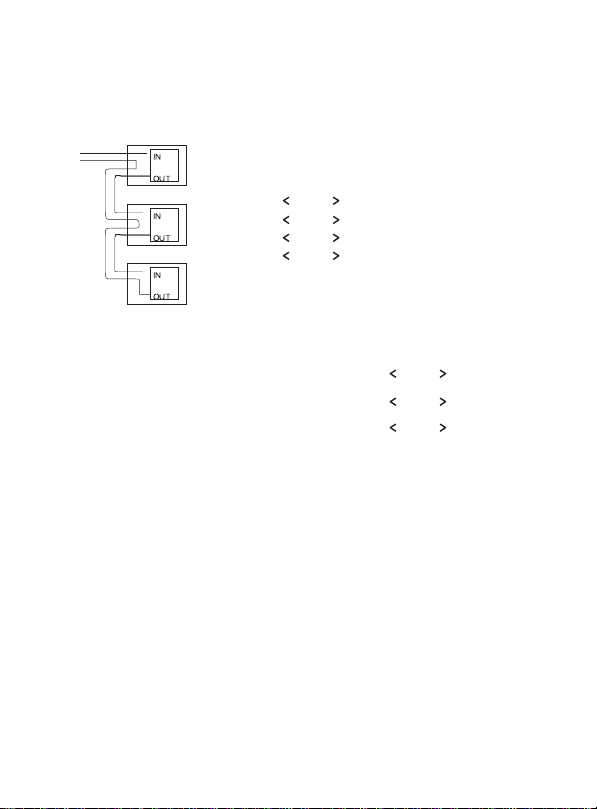
(4) Connection between cameras
Using RS422 bus cascade connection mode, the output of camera 1 is connected to the
input of camera 2, the output of camera 2 is connected to the input of camera 3, and so on.
As below:
VISCA Equipment
CAMERA1 CAMERA2 CAMERA3
TXD OUT+
TXD OUTRXD OUT+
RXD OUT-
RS232 cascade connection CAMERA1 CAMERA2 CAMERA3
The output of camera 1 is connected to the
input of camera 2, the output of camera 2 is
connected to the input of camera 3, and so
on.
.............
.............
.............
.............
RXD IN+
RXD INTXD IN+
TXD IN-
TXD
RXD
GND
... ...
.............
.............
.............
RXD
TXD
GND
... ...
Page 7
2.Buttons Description
2.1 Buttons Description
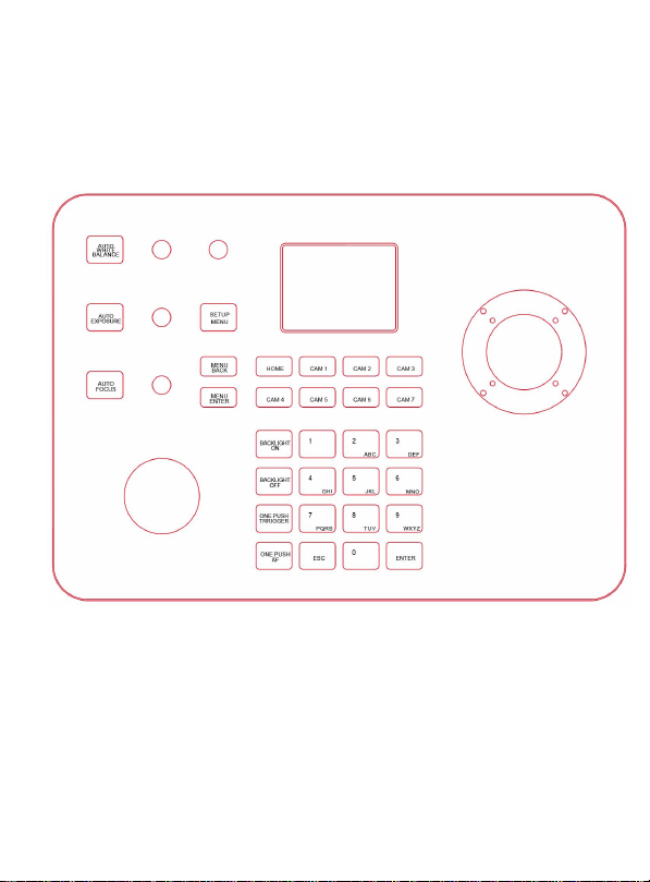
[AUTO EXPOSURE]: Click the button to enter the automatic adjustment screen exposure mode.
[AUTO WHITE BALANCE]: Click the button to select the white balance setting
[AUTO FOCUS]: Click the button to set the focus of the camera on the object
[CAM1 - 7]: Switch devices quickly
[SETUP/MENU]: 1. Press and release to enter the joystick setup menu.
2. Press and hold to activate camera OSD menu.
-06-
Page 8

Controller
setting
Description
1.Add
network
device
Camera
The jo ystick ID of camera can be filled in 1-7; after
adding camera a ll information p ress [ENTER] to save.
Protocol
Optional: VISCA (UPD), SONY VISCA (UDP), VISCA (TCP),
ONVIF, select the corresponding p rotocol of the camera
IP address
Camera IP add ress
Port
Input the camera port nu mber
Username
& Password
Input the camera username and password
2.Add
analog
device
Camera
The joystick ID of ca mera can be filled in 1-7, after
adding camera all information press [ENTER] to save
Protocol
Select the protocol corresponding to the camera
Address
code
Select the ad dress code corresponding to the camera
Baud rate
Select the ba ud rate corresponding to th e camera
3.Device list
Added camera list can be reviewed by moving the joystick up and down.
Press the button on the top of the joystick or press [ENTER] to confirm
4.Network
properties
Network
properties
Switch throu gh Joystick left and right, press [ENTER] to con firm
Dynamic
Dynamic allocation based on switch settings
Static
Manually enter IP address information
5. Device Language:
EN/Chinese
Switch through Joystick left and right, press [ENTER] to confirm
6. Key tone
Switch through Joystick left and right, press [ENTER] to confirm
7. Reset
Double press [ENTER] to reset, press [ESC] to cancel
8. System i nformation
Check the controller software, hardware, Web version,
gateway and subnet mask
[MENU BACK]: While in the camera OSD press this button to go back one level
[MENU ENTER]: While in the camera OSD press to confirm/advance one level
[BACKLIGHT ON]: Press to enable Backlight Control (BLC)
[BACKLIGHT OFF]: Press to disable Backlight Control (BLC)
[ONE PUSH TRIGGER]: Press to trigger white balance
[ONE PUSH AF]: Press to trigger auto focus
-07-
Page 9
-08-
[0-9]: Number key preset (Press and hold to set preset), (short press to recall
preset)
Example:
• Set No. 1 preset: Move the camera to the position
where you want to set preset- press and hold [1]
• Recall No.1 preset: short press [1]
[ESC]: Exit
[ENTER]: Confirm
2.2 Joystick rotations description
• ZOOM SPEED/PT SPEED: Zoom/PTZ speed adjustment
Turn the knob right to increase speed, left to decrease speed. Press the knob to switch the
adjustment type.
• IRIS: Adjust Exposure
Turn the knob to the right to open iris, tu rn left to close ir is.
Pres s [AUTO EXPOSURE] to enable/disable manual iris control.
• RGAIN/BGAIN: Red/Blue gain
Turn the knob right to inc rease gain, left to decrease gain.
Press the knob to switch the gain type.
Pres s [AUTO WHITE BALANCE] to enable/disable manual color correction.
• NEAR/FAR: Turn the knob right to adjust focus toward distant objects, turn the know
left to adjust focus toward near objects.
Pres s [AUTO FOCUS] to enable/d isable manu al focus control.
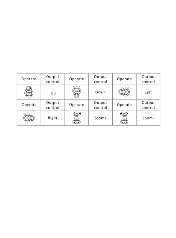
• Joystick Rotation: Rotate joystick handle clockwise to zoom in, counterclockwise to zoom out.
• Zoom Knob: Rotate knob clockwise to zoom in (telephoto), rotate counterclockwise to zoom
out (wide angle).
Page 10
3. Add device
Network Device
Camera
Protocol
IP Add
Port
Device List
Camera : 3
Protocol : ONVIF
IP Add : 192.168.0.245
Port : 80
Protocol : VISCA
Address : 3
Baud rate : 9600
3.1
Add network device
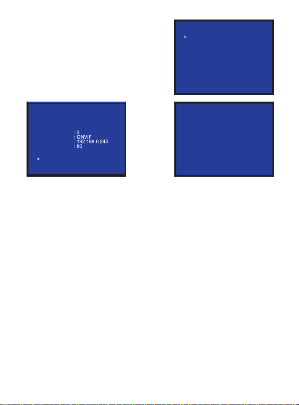
Use the controller to add LAN devices as follows:
(1) Press [SETUP/MENU] to enter the main
menu.
User Name : admin
Password : admin
Keyboard Settings
1. Add N etwork Device
2. Add Analog Device
3. Device List
4. Network Attribute: Static
5. Language: English
6. Button Tone: Off
7. Restore Factory
8. System Info
3/7
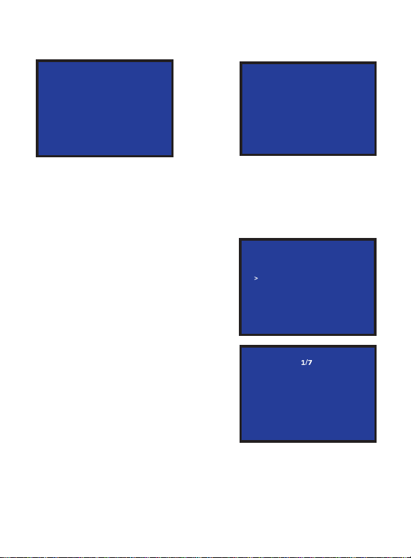
(2) Setup Add Network Device, fill in the
camera, protocol, IP address, port, correct
username and password, and press
[ENTER] to confirm
(3) Enter the device list, use the joystick
up or down to select the device just
added, press the middle button of the
joystick or [ENTER] to control.
-09-
Page 11
3.2 Add analog device
Device List
Keyboard Settings
1.Add Network Device
2.Add Analog Device
3.Device List
4.Network Attribute: Static
5.Language: English
6.Button Tone: Off
7.Restore Factory
8. System Info
Camera : 1
Protocol :
Native IP 192.168.0.185
Camera
Network I/F
Target IP :
Analog interface
Target I/F
baud rate
Address
Active I/F : Analog
:
1
:
ONVIF
192.168.0.181
:
8999
:
PELCO-D
: 9600
: 1
Analog Device
Address :
Baudrate :
PELCO-D
192.168.0.245
9600
(1) Long press the bu tton on top of the joystick han dle to switch the analog mode.
(2) Press [SETUP/MENU] button to enter the setting interface, select to add analog device.
(3) Enter the device adding interface, select the camera with 1-7 digital number, select the
corresponding analog protocol, select the address code corresponding to the camera,
select the baud rate, and press [ENTER] to confirm the addition.
4. Review & Control
(1) Press the [SETUP/MENU] button to enter the
settings interface, move the joystick up and down
to select the device list, press the [ENTER] button
to view the added device.
(2) Review the saved devices by mo ving the
joystick up and down, press the button on top of
the joystick handle or the [ENTER] button to select
the camera to be controlled.
(3) When the screen shows that the connection is
successful, the controller has been connected to
this IP device. At this time, you can begin
controlling the camera.
Camera : ONVIF
Protocol
IP Add : 8999
Port : VISCA
Protocol : 1
Address : 9600
Baudrate :
1
:
192.168.0.181
-10-
Page 12
5. Network Configuration
5.1 Homepage connection and login
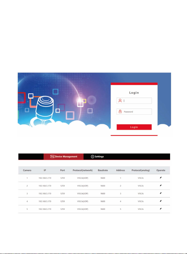
Connect the power cable of the controller and connect the network cable. After keyboard
start-up is complete, the device IP: 192.168.x.xxx will be displayed on the display. Enter this IP
address into the browser to access the configuration page. The initial login is:
username: admin
password: none
(1) Connect the controller and computer in the same LAN, enter the controller IP address in the
browser. The page displays as follows:
(2) default username= admin password= empty (no password)
-11-
Page 13
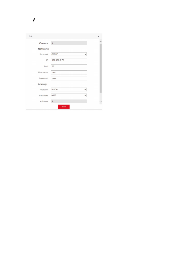
(3) Click button to add and modify device parameters in the local area network, the
page displays as follows:
Input the device number,
corresponding IP address, port
number and username. Click Save.
-12-
Page 14
5.2 Web network settings
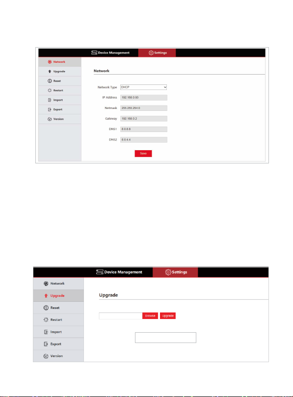
LAN settings can modify the device's IP acquisition method and port parameters, as shown below:
Static address (STATIC): User defined IP address
Dynamic address (DHCP) (default): The controller will automatically request an IP address
from the router, after the request is successful it will be displayed on the display as:
“Local IP: xxx.xxx.xxx.xxx”
5.3 System Upgrade
The upgrade function is used for performing firmware updates. Select the correct upgrade
file from the Browse menu and click up grade. After the upgrade is complete, the device will
automatically restart.
Note: Do not perform any op eration on the device during its upgrade, a nd do not power off or
disconnect the network!
-13-
Page 15
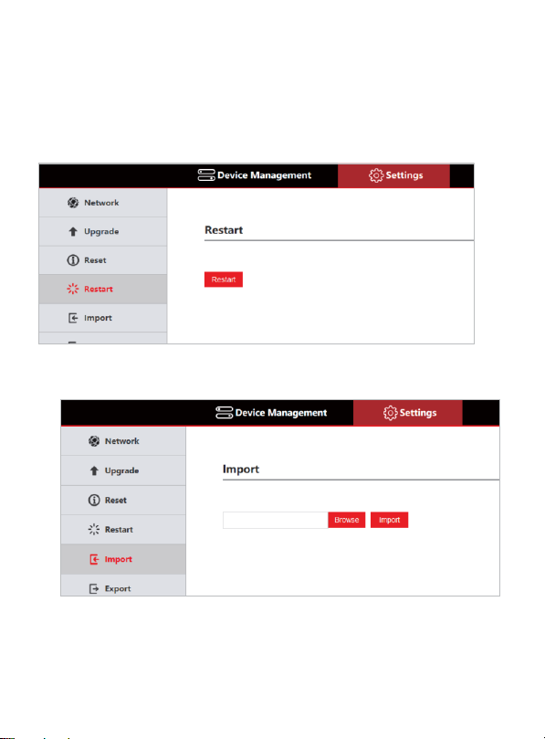
5.4 System reset
Clear all data and perform a factory reset.
5.5 Restart
Perform a reboot of the controller.
5.6 Import configuration
Import a previous configuration.
-14-
Page 16
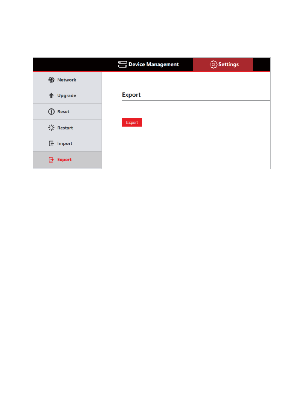
5.7 Export configuration
Export the related information of the current controller added multiple devices, which can be
exported to other controller devices.
-15-
Page 17
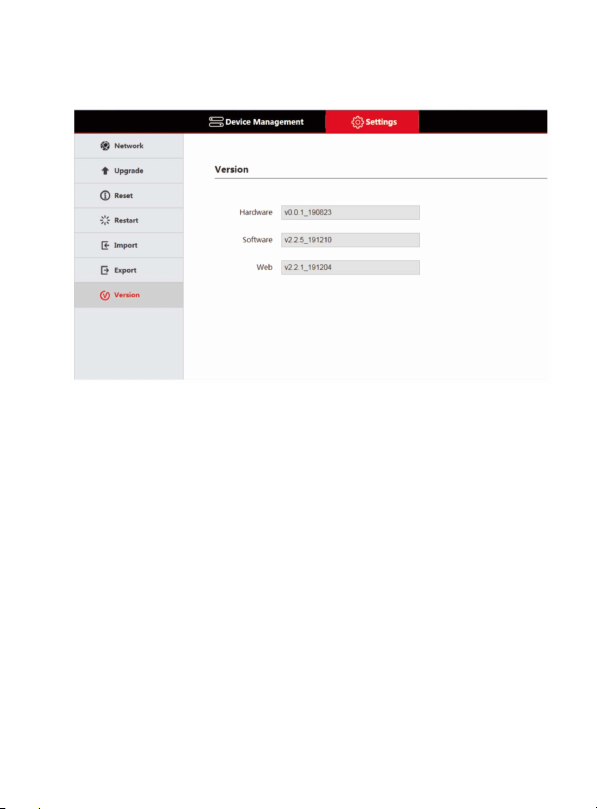
5.8 Version information
Display the software and hardware information of the current controller.
6. Troubleshooting
1. If the screen displays "Connection failed", check IP information is correct for the
camera. Verify controller and camera are on the same subnet.
2. If the screen displays "Username and password are incorrect", please check
whether the added device username and password are correct.
3. If the camera does not respond to the joystick while in VISCA UDP mode enter the
controller setup menu and set option 9: VISCA RESPONSE to DISABLE.
-16-
Page 18
7. Tech Support
Before contacting tech support, we may have answered your question already! Visit our BZBGEAR
support page at bzbgear.com/support for valuable information on our products.
Here you will find our Knowledge Base (bzbgear.com/knowledge-base) consisting of tutorials, quick
start guides, and step-by-step troubleshooting instructions. Also visit our YouTube channel BZB TV at
youtube.com/c/BZBTVchannel for help setting up, connecting, and other how-to videos regarding our
products.
If you still need answers, please call 1.888.499.9906, email [email protected], or chat at
bzbgear.com.
8.Warranty
BZBGEAR Pro AV products and Cameras come with a three-year warranty. An extended two-year
warranty is available for our Cameras upon registration for a total of five years.
For an extended two-year warranty on our Cameras, follow these steps:
1. Register your Camera within 90 days of purchase by visiting bzbgear.com/warranty.
2. Complete the registration form. Provide all necessary proof of purchase details, including
serial number and a copy of your sales receipt.
For complete warranty information, please visit bzbgear.com/warranty or scan the QR code
below.
9.Mission Statement
BZBGEAR manifests from the competitive nature of the audiovisual and live streaming industry to
innovate while keeping the customer in mind. AV solutions can cost a pretty penny, and new
technology only adds to it. We believe everyone deserves to see, hear, and feel the advancements
made in today’s AV world without having to break the bank. BZBGEAR is your answer for applications
requiring the latest pro AV and live streaming solutions.
You’ll notice comparably lower prices with BZBGEAR while the performance and quality are on par
with the top brands in the industry. Our team offers system design consultation and expert tech
support seven days a week for all BZBGEAR products. Our unparalleled support is our way of showing
we care for every one of our customers. Whether you’re an integrator, home theater enthusiast, or a
do-it-yourselfer, BZBGEAR offers solutions allowing you to focus on your project and not your budget.
-17-
Page 19

Page 20

 Loading...