

Page 1
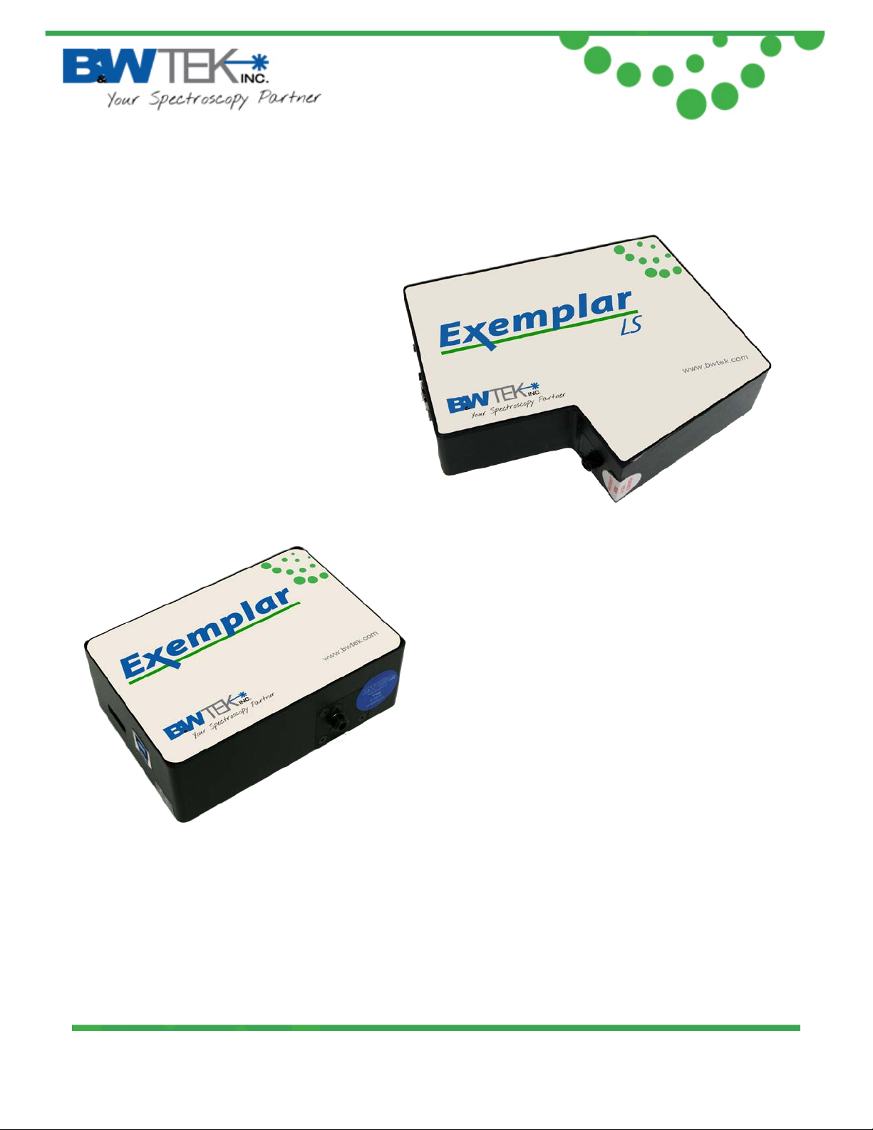
Exemplar®
Smart CCD Spectrometer
User Manual
19 Shea Way, Newark, DE 19713 • Tel: (302) 368-7824 • Fax: (302) 368-7830 • Web: www.bwtek.com
290020230-D (4/20/2015) Copyright 2015 B&W Tek, Inc.
Page 1 of 23
Page 2
®
Exemplar
Table of Contents
1. Introduction ____________________________________________________________________ 3
2. Exemplar Spectral Acquisition Modes ________________________________________________ 3
2.1. Normal Scan Mode ___________________________________________________________________3
2.2. Smart Scan Mode ____________________________________________________________________3
2.3. Burst Scan Mode _____________________________________________________________________4
3. Specifications ___________________________________________________________________ 4
4. Check Contents __________________________________________________________________ 5
5. Installation _____________________________________________________________________ 5
6. Operating Software BWSpec Quick Start Guide ________________________________________ 6
6.1. Getting to know BWSpec graphic user interface ____________________________________________6
6.2. Quick Start __________________________________________________________________________6
7. Auxiliary Port Function ____________________________________________________________ 8
7.1. External Trigger Function ______________________________________________________________8
8. Hardware Setup _________________________________________________________________ 8
8.1. Digital Input Section: _________________________________________________________________9
8.2. Temperature Monitor Section: _________________________________________________________11
8.3. Analog Input Section: ________________________________________________________________12
8.4. Analog Output Section: _______________________________________________________________13
8.5. Digital Output Section: _______________________________________________________________14
8.6. Data Scan Mode Section: _____________________________________________________________15
8.7. Pulse Output, BRC115P PulseOut _________________________________________________ 19
8.8. Programmable Delay T ime ______________________________________________________ 20
Appendix A: Dimensional Drawing - BRC115P-V __________________________________________ 21
Appendix B: Dimensional Drawing - BRC115P-U __________________________________________ 22
Appendix C: Auxilary Port Pin Assignments ______________________________________________ 23
19 Shea Way, Newark, DE 19713 • Tel: (302) 368-7824 • Fax: (302) 368-7830 • Web: www.bwtek.com
290020230-D (4/20/2015) Copyright 2015 B&W Tek, Inc.
Page 2 of 23
Page 3
Processing
Estimated Time Needed
Smoothing
23.5 (ms)
Dark Compensation
7.2 (ms)
Averaging N Time
T = 4.55(ms) x N + 8.13 (ms)
®
Exemplar
1. Introduction
The Exemplar® is the next step in the evolution of miniature CCD spectrometers. It is the first
smart spectrometer featuring on board data processing, USB 3.0 communication, and
temperature compensation. The Exemplar is also optimized for multi-channel operation
featuring ultra-low trigger delay, ultra-low gate jitter, and super speed data transfer. Additionally,
the Exemplar features a 2048 element detector and a built-in 16-bit digitizer with a >2.0 MHz
readout speed.
2. Exemplar Spectral Acquisition Modes
There are three spectral acquisition modes as described below.
2.1. Normal Scan Mode
In this acquisition mode, the spectrometer acquires data which is received by the PC/Software
through the USB. The user can then perform post data manipulation such as averaging,
smoothing, and dark compensation. Continuous spectra acquisition is possible in nor mal scan
mode. At an integration time of 1.0ms the maxi mum frame rate is less than 500 spectra per
second in this mode.
2.2. Smart Scan Mode
Smart Scan allows for data manipulation to take place in the Exemplar’s on-board processor
including averaging, smoothing, and dark compensation, in that or der. The user has the ab ilit y to
send a command with flags for each of the methods. The internal data processing engine can
handle any combination of these methods.
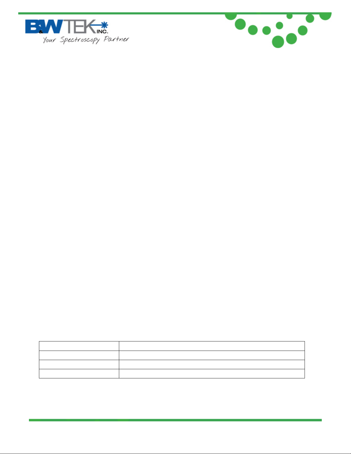
Table 1 details the fram e rate at different combinations of methods at an integrat ion t im e of 1m s.
19 Shea Way, Newark, DE 19713 • Tel: (302) 368-7824 • Fax: (302) 368-7830 • Web: www.bwtek.com
290020230-D (4/20/2015) Copyright 2015 B&W Tek, Inc.
Page 3 of 23
Page 4
®
Exemplar
2.3. Burst Scan Mode
This is the fastest spectral acquisition mode. After a burst mode, spectral acquisition command
is received, and the internal spectral acquisition engine will continuously send the spectra back
to the PC until the preset number of spectra is reached. In this mode the minimum integration
time must be set to 1050us, as the events of signal integration and spectral readout plus
sending of data are processed simultaneously. There is no time gap between the consecutive
integration periods, which enables this spectrometer to be a suitable device for time-of-flight
event capturing.
3. Specifications
See product data sheets for specifications for t he E x em plar model BRC115P-V and B RC 115 P-U
(model LS)
19 Shea Way, Newark, DE 19713 • Tel: (302) 368-7824 • Fax: (302) 368-7830 • Web: www.bwtek.com
290020230-D (4/20/2015) Copyright 2015 B&W Tek, Inc.
Page 4 of 23
Page 5
®
Exemplar
4. Check Contents
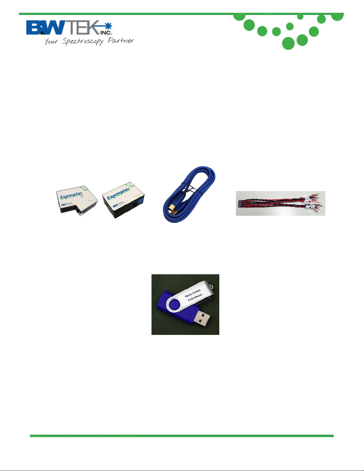
Before installation please check your system contents. They may include:
• Exemplar™ Spectrometer unit
• USB 3.0 Cable
• AUX Port Cable
• BWSpec4TM software on a USB Drive
Exemplar™ Spectrometer USB 3.0 Cable
Aux Port Cable
Software USB Drive
19 Shea Way, Newark, DE 19713 • Tel: (302) 368-7824 • Fax: (302) 368-7830 • Web: www.bwtek.com
290020230-D (4/20/2015) Copyright 2015 B&W Tek, Inc.
Page 5 of 23
Page 6
®
Exemplar
5. Installation
Software / Hardware Installation:
There is a BWSpec installation guide located on your USB drive. Refer to this guide for full
installation instruct ions
6. Operating Software BWSpec Quick Start Guide
6.1. Getting to Know BWSpec Graphic User Interface
The BWSpec operating software has a graphic user interface which consists of a menu bar,
quick access bar, gr aphic area, message bar and control panel.
Reference the BWSpec4TM user manual located on your USB drive for more information on how
the software works.
6.2. Quick Start
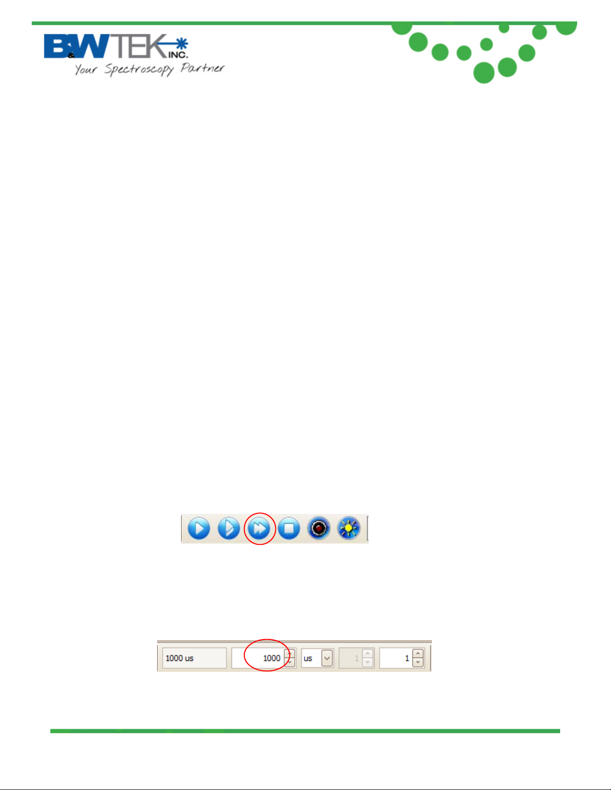
1. Run BWSpec from the shortcut icon that will have been placed on your desktop after
installation.
2. From the toolbar, select “Acquire Continuously”
3. Aim the spectrometer’s SMA port (light input) towards a broadband light source; for
example a tungsten bulb, light bulb, or overhead lights.
4. You should see a spectral response being displayed in the BWSpec4TM software window.
The spectral response will change if the integr ation time is adjusted from the toolbar.
19 Shea Way, Newark, DE 19713 • Tel: (302) 368-7824 • Fax: (302) 368-7830 • Web: www.bwtek.com
290020230-D (4/20/2015) Copyright 2015 B&W Tek, Inc.
Page 6 of 23
Page 7
®
Exemplar
Note: There are different ways in which light can be directed into the spectrometer ’s SMA port
and different light sources which can be used.
For more information on these types of setups, please visit our website: www.bwtek.com.
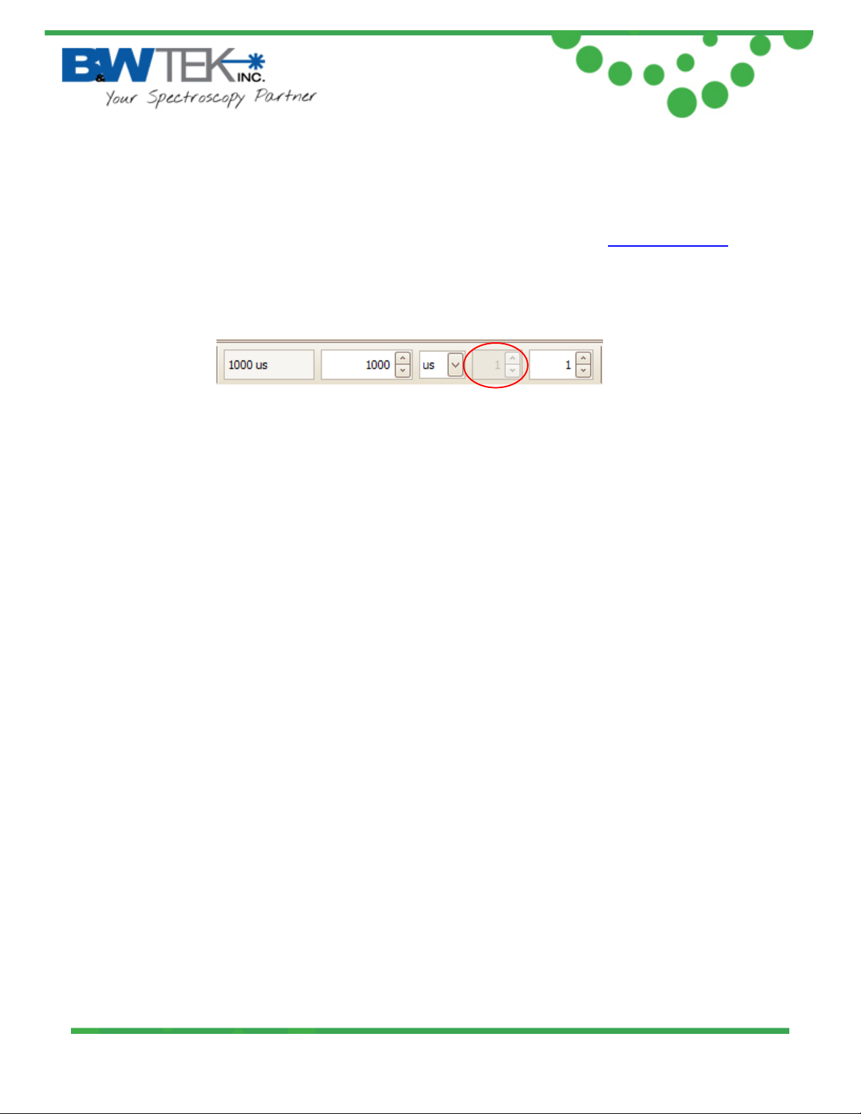
Multiplier Function
When using the Exemplar spectrometer, the “Multiplier” function is not available and will be
greyed out:
19 Shea Way, Newark, DE 19713 • Tel: (302) 368-7824 • Fax: (302) 368-7830 • Web: www.bwtek.com
290020230-D (4/20/2015) Copyright 2015 B&W Tek, Inc.
Page 7 of 23
Page 8
®
Exemplar
7. Auxiliary Port Function
Exemplar is capable of monitoring and controlling both digital and analog signals through the
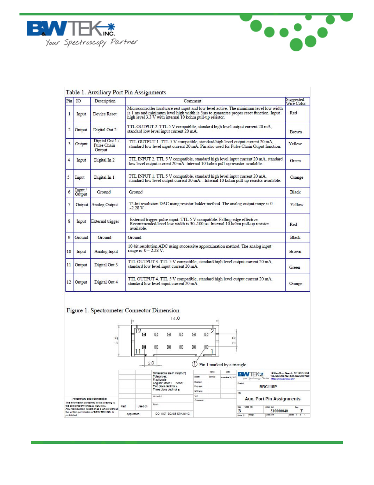
auxiliary port on the side of the spectrometer. See Appendix C for a table containing the
description and function details for each pin of the auxiliary port. These standard functions are
accessible through SDK. Moreover, if the customer wants to create their own input/output
correlations, B&W Tek can configure a customized pin definition.
7.1. External Trigger Function
The Exemplar has a built in external trigger option. External triggering of the spectrometer can
be achieved by using the 12 pin connector located at the rear panel of the spectrometer and its
associated pins. Make sure that the external trigger checkbox under the “Acquire Control” menu
in BWSpec is checked before the spectrometer can be ready to respond to an external trigger.
The typical time delay between arrival of a falling edge and the start of a new integration time is
less than 35ns. Within the specified short delay, the spectrometer will begin a new integration
period and will last for a complete integration cycle (Ex: 1 scan with 10 averages requires only
10 pulse). The supplied trigger signal is required to be a TTL compatible pulse with an optimal
width of 30~100us. The trigger is falling edge effective. The maximum trigger signal voltage
should not exceed +5.5 V DC. To disable the external trigger mode, check off the option in the
checkbox under the “Acquire Control” menu.
Go to Appendix C – Aux Port for pins assignments
8. Hardwar e Setup
The Exemplar allows for advanced hardware control features which can be found by following
the path below.
Menu Bar Setup Hardware Setup
Click on the “BRC115 (Exemplar)” tab
19 Shea Way, Newark, DE 19713 • Tel: (302) 368-7824 • Fax: (302) 368-7830 • Web: www.bwtek.com
290020230-D (4/20/2015) Copyright 2015 B&W Tek, Inc.
Page 8 of 23
Page 9
Exemplar
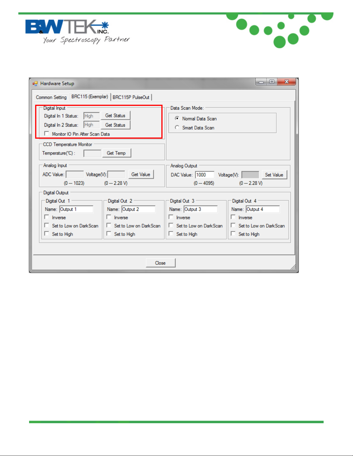
8.1. Digital Input Section:
®
The “Get Status” button will return a ‘High’ or ‘Low’ value depending on the TTL Digital Signal
being applied to the ‘Digital In 1’ and ‘Digital In 2’ pins.
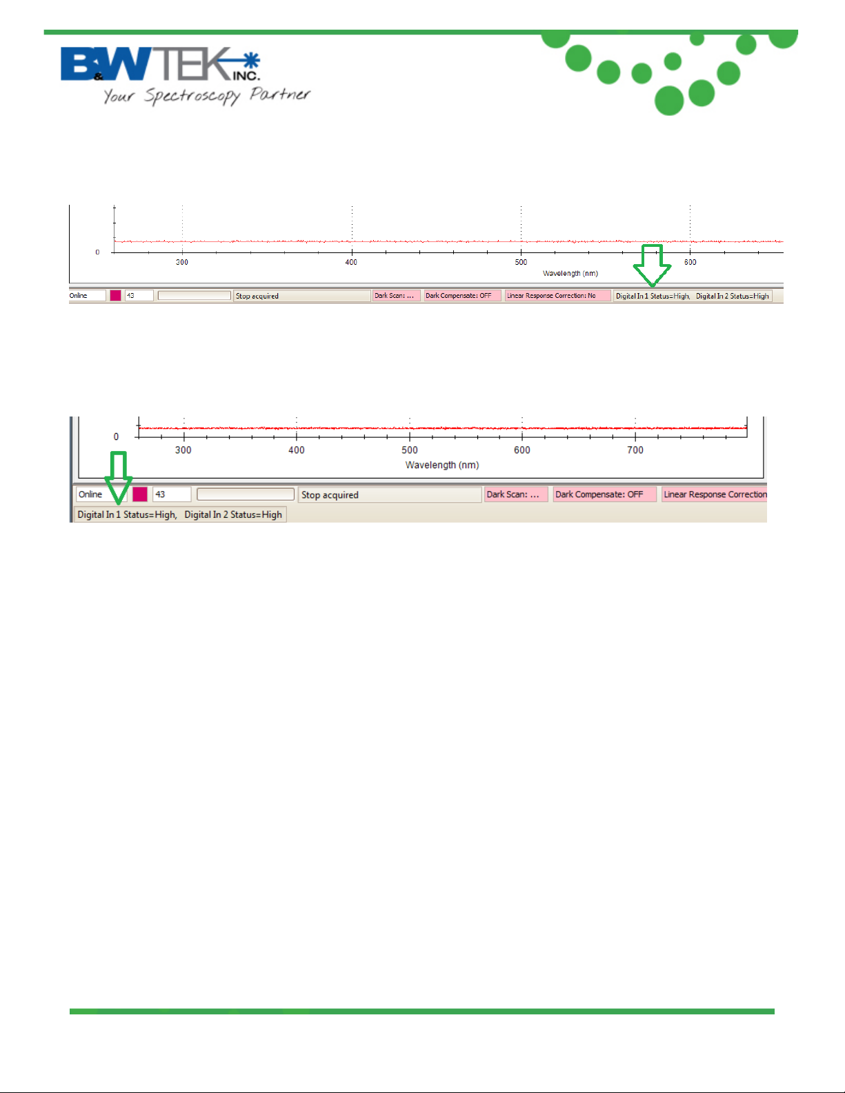
Monito r IO Pin Aft er Scan: when enabled the Status of the ‘Digital In 1’ and ‘Digital In 2’ pins
will be updated after each scan. Th e Digi tal In 1 Status and Digital In 2 Status will be displayed
below the graph in the main BWSpec Window. Statuses will appear after the first acquisition.
Location will vary depending on the size of the main BWSpec window.
19 Shea Way, Newark, DE 19713 • Tel: (302) 368-7824 • Fax: (302) 368-7830 • Web: www.bwtek.com
290020230-D (4/20/2015) Copyright 2015 B&W Tek, Inc.
Page 9 of 23
Page 10
Exemplar
“Full Screen” Window Display
“Reduced”/”Minimized” Window Display
®
19 Shea Way, Newark, DE 19713 • Tel: (302) 368-7824 • Fax: (302) 368-7830 • Web: www.bwtek.com
290020230-D (4/20/2015) Copyright 2015 B&W Tek, Inc.
Page 10 of 23
Page 11
Exemplar
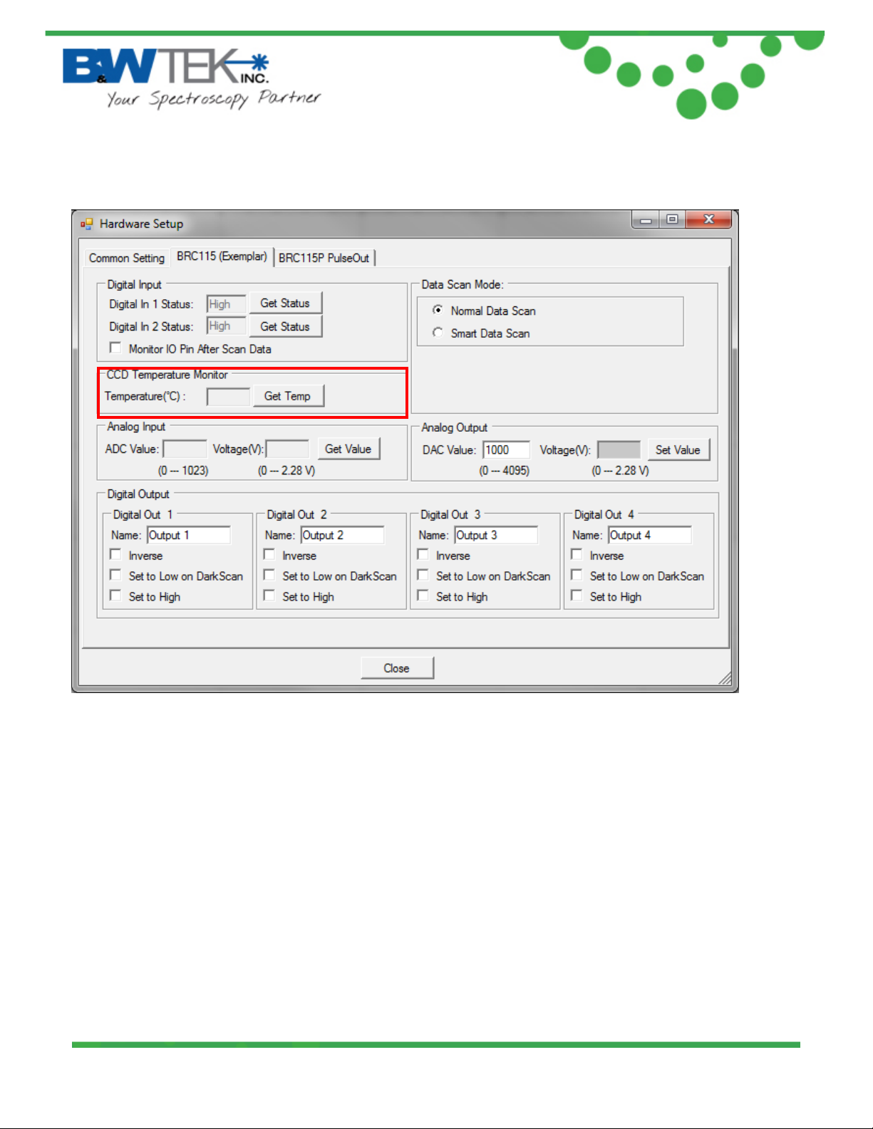
8.2. Temperature Monitor Section:
®
The “Get Temp” button will return the temperature of the PCB, which i s al so the CCD sensor
reference temperature.
19 Shea Way, Newark, DE 19713 • Tel: (302) 368-7824 • Fax: (302) 368-7830 • Web: www.bwtek.com
290020230-D (4/20/2015) Copyright 2015 B&W Tek, Inc.
Page 11 of 23
Page 12
Exemplar
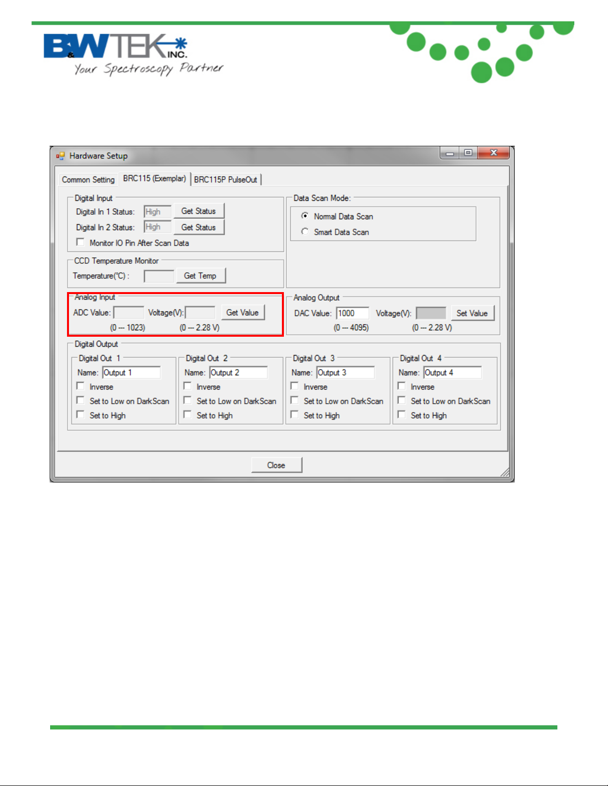
8.3. Analog Input Section:
®
ADC Value: will return the digital value of the analog signal applied to the “Analog Input” pin.
ADC Value = (Voltage / 2.28) * 1024
Voltage (V): will return the analog voltage value of the analog signal applied to the “Analog
Input” pin.
Voltage = (ADC value / 1024) * 2.28
(Reference the “Auxiliary Port Function” section in this user manual)
19 Shea Way, Newark, DE 19713 • Tel: (302) 368-7824 • Fax: (302) 368-7830 • Web: www.bwtek.com
290020230-D (4/20/2015) Copyright 2015 B&W Tek, Inc.
Page 12 of 23
Page 13
Exemplar
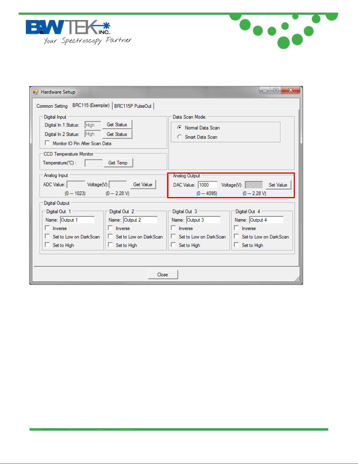
8.4. Analog Output Section:
®
DAC Value: can be set to a 12-bit digital signal range f rom 0 – 4095 when the “Set Value” button
is pressed. This will output a voltage range of 0 – 2.28 volts to the “Analog Output” pin.
Voltage = (DAC value / 4096) * 2.28
(Reference the “Auxiliary Port Function” section in this user manual)
19 Shea Way, Newark, DE 19713 • Tel: (302) 368-7824 • Fax: (302) 368-7830 • Web: www.bwtek.com
290020230-D (4/20/2015) Copyright 2015 B&W Tek, Inc.
Page 13 of 23
Page 14
Exemplar
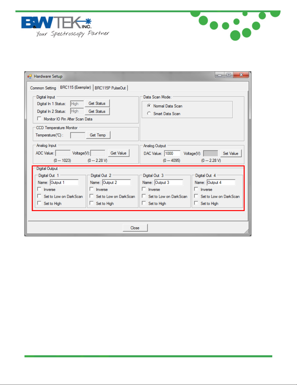
8.5. Digital Output Section:
®
“Digital Out 1” – “Digi tal Out 4” sections relate to the corresponding “Digi tal Out #” pin on the
Auxiliary Port.
(Reference the “Auxiliary Port Function” section in this user manual)
• “Name:” field can be renamed to an application appropriate function, which will be
displayed under the “Acquire Control” section the BWSpec 4 main window.
• Inverse Checkbox: When activated, inverts the output status.
• Set to Low on Dark Scan: This will output the configured signal through the
corresponding digital out pin when a dark scan is taken in BWSpec. (For example, you
could use this to close an external shutter)
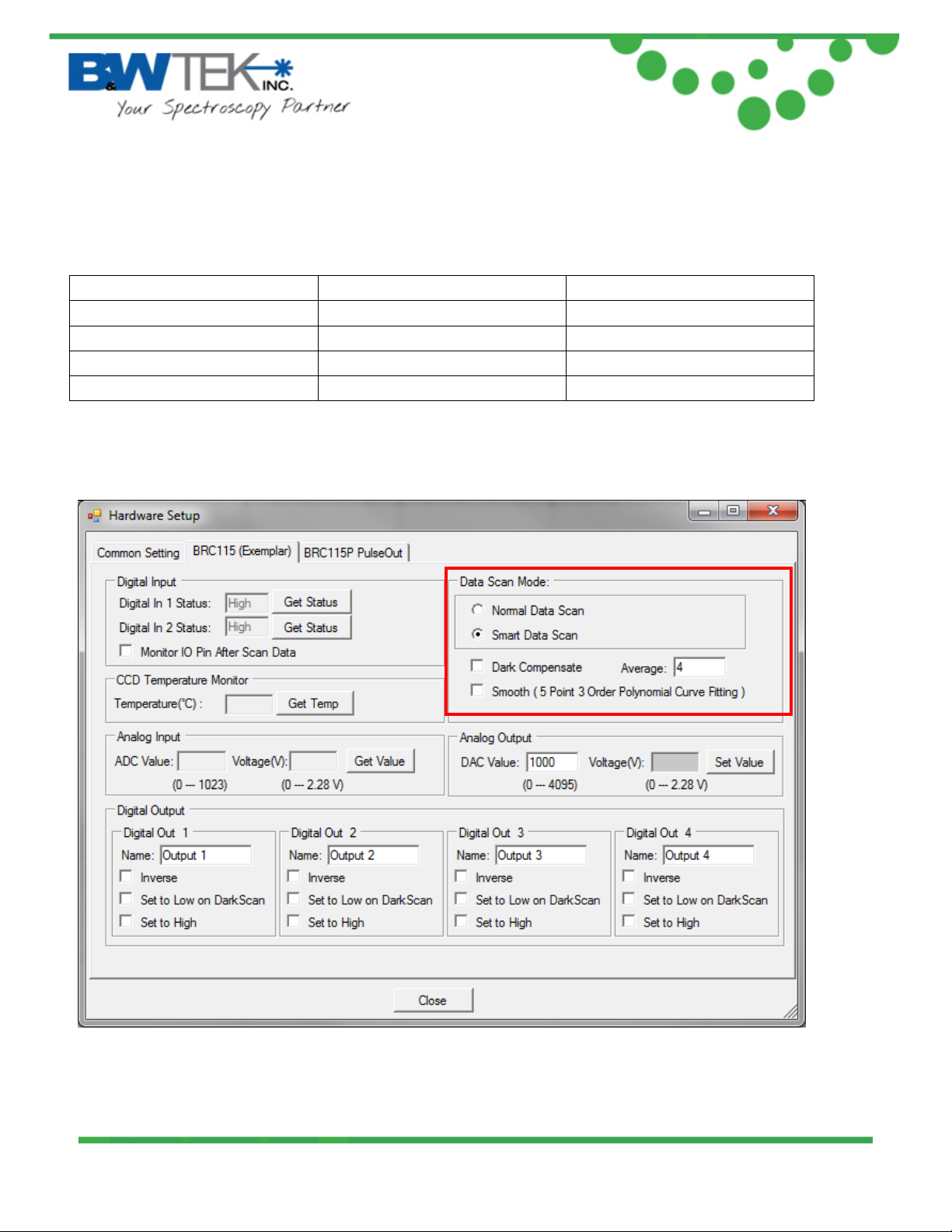
• Set to High: By default the output signals are set to LOW. When checked, the output is
set to HIGH through the corresponding digital out pin. When enabled the checkbox
19 Shea Way, Newark, DE 19713 • Tel: (302) 368-7824 • Fax: (302) 368-7830 • Web: www.bwtek.com
290020230-D (4/20/2015) Copyright 2015 B&W Tek, Inc.
Page 14 of 23
Page 15
Inverse Check Box
Set to High Check Box
Output (0 = LOW, 1 = HIGH)
0 0 0 0 1 1 1 0 1 1 1
0
®
Exemplar
status will also be reflected under the “Acquire Control” section the BWSpec4 main
window.
Reference the following “Truth Table” for output signal configurations.
Truth Table:
8.6. Data Scan Mode Section:
19 Shea Way, Newark, DE 19713 • Tel: (302) 368-7824 • Fax: (302) 368-7830 • Web: www.bwtek.com
290020230-D (4/20/2015) Copyright 2015 B&W Tek, Inc.
Page 15 of 23
Page 16
®
Exemplar
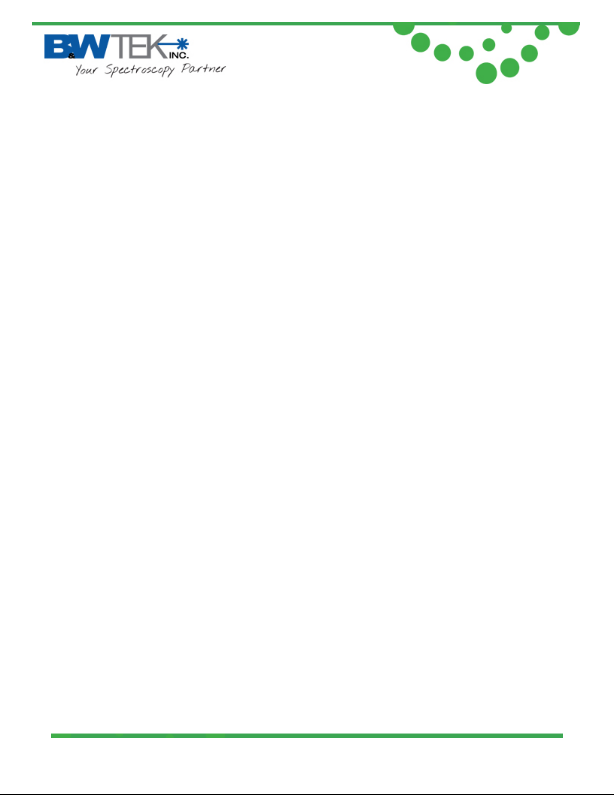
The Exemplar has three data scan modes, Normal Scan, Smart Scan and Burst Scan.
8.6.1. Normal Data Scan
“Normal Data S can”, w hen se lecte d, allows the spectrom eter to ac qu ire and transmit data.
Data manipulation is then accomplished on the software/computer. Averaging, smoothing
and dark compensation can be acqu ired and controlled here, for example.
8.6.2. Smart Data Scan:
“Smart Data Scan” allows for data manipulation to take place inside the spectrometer
allowing for smart spectra acquisition. Smart scan features are:
• Dark Compensate: This will automatically adjust the baseline of the spectrometer so
that the dark current is automatically removed from the collected data.
• Average: X number of scans will be taken at the given integration time and the average
of all of these scans will be displayed in BWSpec. Hardware averages are limited to a
maximum of 255 scans.
• Smooth: Smoothing will be applied to all data outputted to BWSpec.
8.6.3. Burst Data Scan
Burst mode allows for the fastest data acquisition possible in the spectrometer by limiting
overhead processing from data transfer to the computer and saving data. In burst mode,
the spectrometer will continuously acquire and transfer data to the PC without a time gap
between successive spectra.
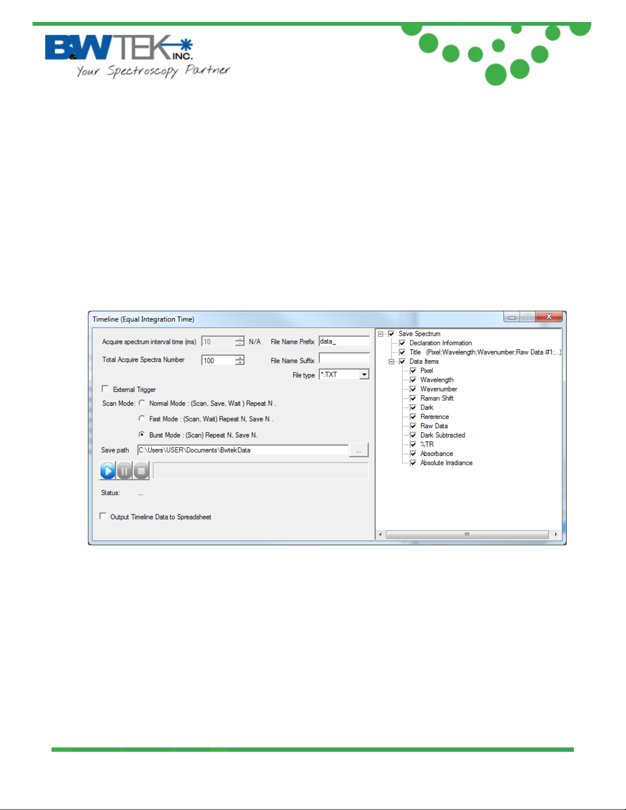
Burst mode is located under the Timeline plugin:
• Enable the Timeline plugin-
Menu Bar --> Plug-in --> Plug-in Manager
Locate the "Timeline Plug-in" and enable the Check box.
Click "OK" to enable.
• Open Timeline from the menu-
Menu Bar --> Tools --> T im eline --> T im eline (Equal Integration Time)
19 Shea Way, Newark, DE 19713 • Tel: (302) 368-7824 • Fax: (302) 368-7830 • Web: www.bwtek.com
290020230-D (4/20/2015) Copyright 2015 B&W Tek, Inc.
Page 16 of 23
Page 17
®
Exemplar
Notes:
• Burst Mode will only work with the set integration time >= 1050us, multiplier = 1 and
averaging = 1 (1050us, or 1.05ms, is the minimum integration time allowed in burst
mode). If the integration time is set to a lower setting, the integration time will be
automatically updated to 1050us in burst data scan.
• The highest number of scans the spectrometer can acquire is 16,000.
• Smart data scan cannot be used in conjunction with burst mode.
• “Time Average” from the main BWSpec window will have no effect when acquiring data.
• “Multiplier” from the main BWSpec window will have no effect when acquiring data.
8.6.3.1. Setup
• Total Acquire Spectra Number: This sets the number of scans to be performed by
the spectrometer.
• File Name Prefix: This sets the prefix for the saved spectra
• File Name Suffix: This sets the suffix for the saved spectra
• File type: This sets the saved file type for the saved spectra.
Options: .txt, .csv, .BWRam, .SPC
• Save path: This sets the location where the data will be saved once complete.
• The right side of the window allows the user to select what specific data is to be
saved.
19 Shea Way, Newark, DE 19713 • Tel: (302) 368-7824 • Fax: (302) 368-7830 • Web: www.bwtek.com
290020230-D (4/20/2015) Copyright 2015 B&W Tek, Inc.
Page 17 of 23
Page 18
®
Exemplar
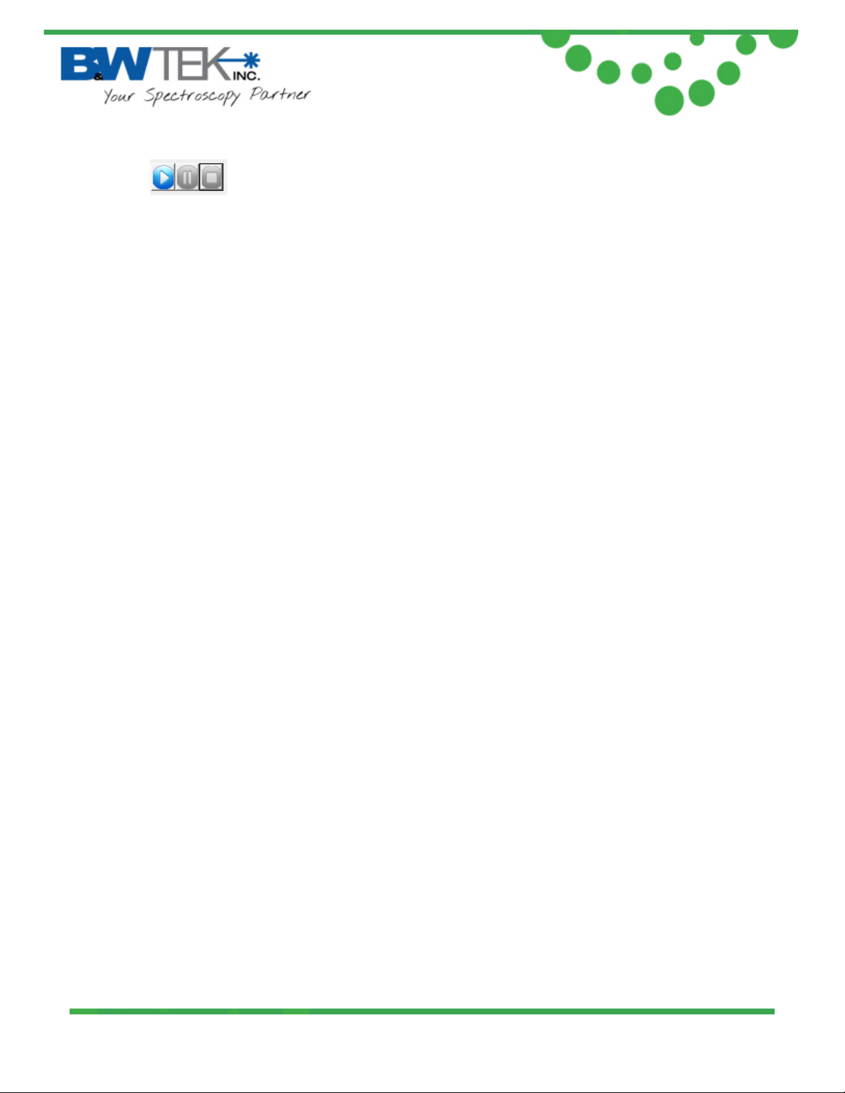
• These control the progress of the burst mode. Press the ‘Play’ button to
begin acquiring.
• Output Timeline Data to Spreadsheet: This outputs the saved data to an Excel
Spreadsheet.
Notes
1. You must have MS Excel installed on your computer for this feature to work.
2. DO NOT click on the excel worksheet while it is being written. This will disrupt the
output process and you will lose the data.
3. For outputting to Excel, you are limited by the maximum number of columns (6) for
the number of scan you can have outputted.
19 Shea Way, Newark, DE 19713 • Tel: (302) 368-7824 • Fax: (302) 368-7830 • Web: www.bwtek.com
290020230-D (4/20/2015) Copyright 2015 B&W Tek, Inc.
Page 18 of 23
Page 19
Exemplar
8.7. Pulse Output, BRC115P PulseOut
®
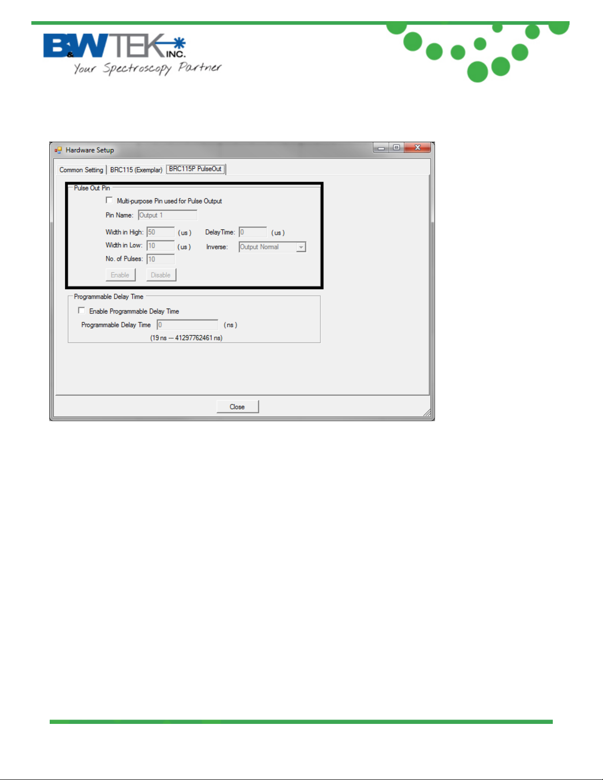
Pulse Chain Output function generates a user configured pulse chain while the spectrometer is
integrating.
• Multi-Purpose Pin Used for Pulse Output: activates this function to be used for the
multi-purpose pin. (See section 7 for pin definitions.)
• Pin Name: User defined name to easily identify function enable/disable under “Acquire
Control” in the spectrometer control panel.
• Width in High: Period of t im e where pulse signal is a T TL high (5V) during 1 pe r iod ( low if
output inverse).
• Width in Low: Period of time w here pulse signal is a TTL low (0V) during 1 period (high if
output inverse).
• No. of Pulses: Determines the number of pulses the spectrometer should send out
during a scan.
• Delay Time: Determines period of time before first pulse is generated.
• Inverse: Allows ability to invert the output signal.
19 Shea Way, Newark, DE 19713 • Tel: (302) 368-7824 • Fax: (302) 368-7830 • Web: www.bwtek.com
290020230-D (4/20/2015) Copyright 2015 B&W Tek, Inc.
Page 19 of 23
Page 20
®
Exemplar
Notes:
• Click “Enable” to send parameters to the spectrometer before taking a measurement.
• “Width in High”, “Width in Low”, and “Number of Pulses” are limited to total integration
time. Set desired integration time before setting parameters for pulse output. Equation is
as follows:
Pulse Time=(Width in High + Width in Low)*No. of Pulses
• Output 1 from digital output (section 8.4) will be disabled while pulse output is activated.
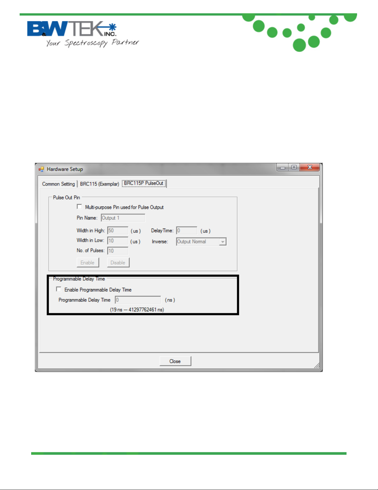
8.8. Programmable Delay Time
“Programamable Delay Time” adds a user defined external trigger delay between when a scan
event is initiated and when the actual scan begins. BRC115P spectrometers can be
programmed to have a external trigger delay betw een 19ns and 41297762461ns (~41 seconds).
19 Shea Way, Newark, DE 19713 • Tel: (302) 368-7824 • Fax: (302) 368-7830 • Web: www.bwtek.com
290020230-D (4/20/2015) Copyright 2015 B&W Tek, Inc.
Page 20 of 23
Page 21
®
Exemplar
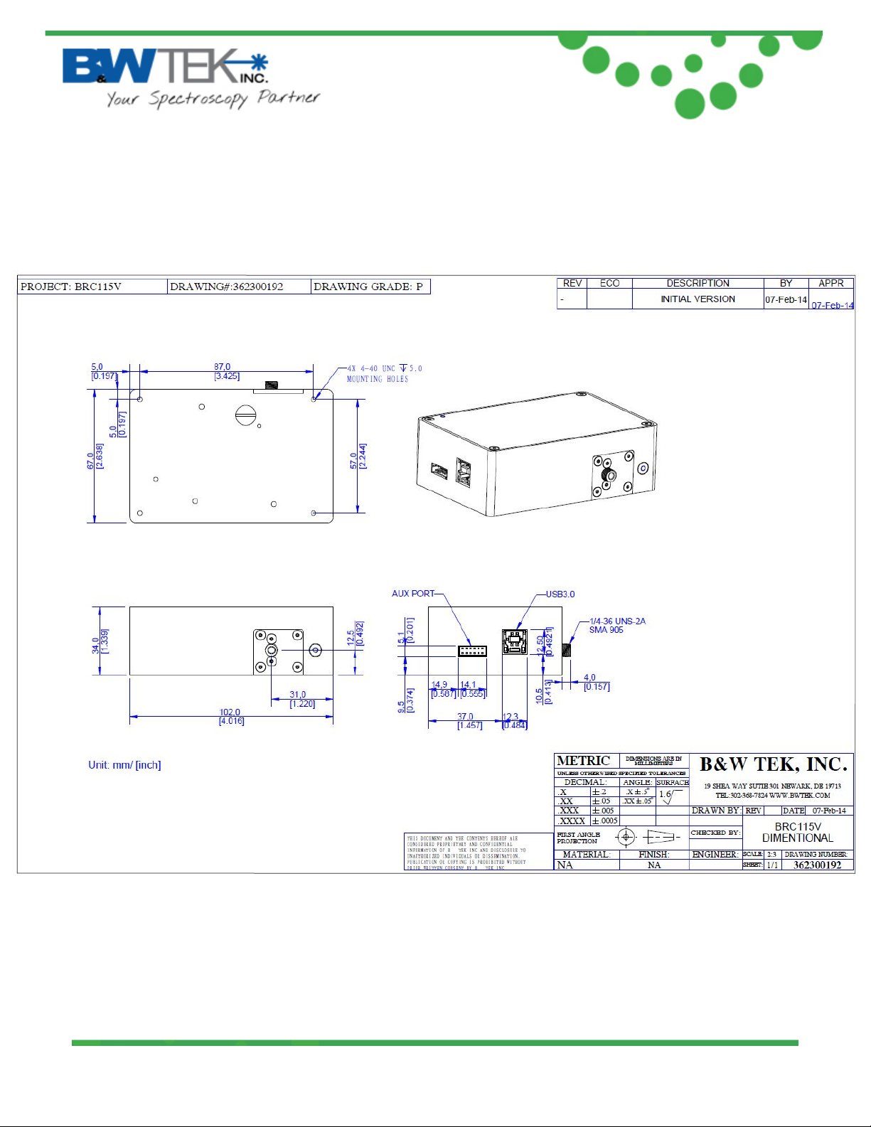
Appendix A: Dimensional Drawing - BRC115P-V
19 Shea Way, Newark, DE 19713 • Tel: (302) 368-7824 • Fax: (302) 368-7830 • Web: www.bwtek.com
290020230-D (4/20/2015) Copyright 2015 B&W Tek, Inc.
Page 21 of 23
Page 22
®
Exemplar
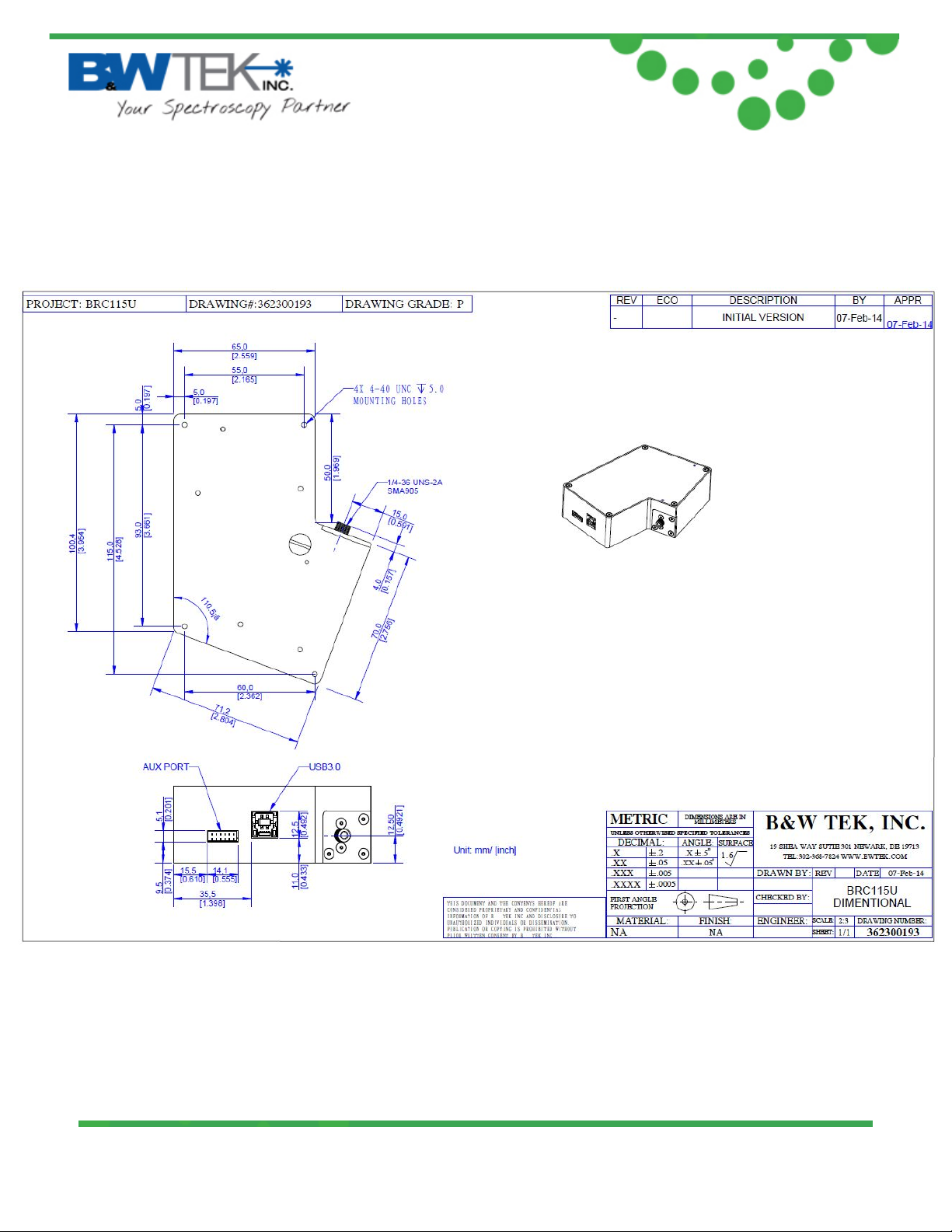
Appendix B: Dimensional Drawing - BRC115P-U
19 Shea Way, Newark, DE 19713 • Tel: (302) 368-7824 • Fax: (302) 368-7830 • Web: www.bwtek.com
290020230-D (4/20/2015) Copyright 2015 B&W Tek, Inc.
Page 22 of 23
Page 23
®
Exemplar
Appendix C: Auxil ary Port Pin Assignments
19 Shea Way, Newark, DE 19713 • Tel: (302) 368-7824 • Fax: (302) 368-7830 • Web: www.bwtek.com
290020230-D (4/20/2015) Copyright 2015 B&W Tek, Inc.
Page 23 of 23
 Loading...