

Page 1

User Manual
Rig Rat III Remote Alarm
Wireless Strobe and/or Siren for Rig Rat III
Page 2

Limited Warranty & Limitation of Liability
BW Technologies LP (BW) warrants this product to be free from defects in material and workmanship under normal use and service for a
period of two years, beginning on the date of shipment to the buyer. This warranty extends only to the sale of new and unused products to
the original buyer. BW’s warranty obligation is limited, at BW’s option, to refund of the purchase price, repair, or replacement of a defective
product that is returned to a BW authorized service center within the warranty period. In no event shall BW’s liability hereunder exceed the
purchase price actually paid by the buyer for the Product.
This warranty does not include:
a) fuses, disposable batteries or the routine replacement of parts due to the normal wear and tear of the product arising from use;
b) any product which in BW’s opinion, has been misused, altered, neglected or damaged by accident or abnormal conditions of
c) any damage or defects attributable to repair of the product by any person other than an authorized dealer, or the installation of
unapproved parts on the product; or
The obligations set forth in this warranty are conditional on:
a) proper storage, installation, calibration, use, maintenance and compliance with the product manual instructions and any other
applicable recommendations of BW;
b) the buyer promptly notifying BW of any defect and, if required, promptly making the product available for correction. No goods shall be
returned to BW until receipt by the buyer of shipping instructions from BW; and
c) the right of BW to require that the buyer provide proof of purchase such as the original invoice, bill of sale or packing slip to establish
that the product is within the warranty period.
THE BUYER AGREES THAT THIS WARRANTY IS THE BUYER’S SOLE AND EXCLUSIVE REMEDY AND IS IN LIEU OF ALL OTHER
WARRANTIES, EXPRESS OR IMPLIED, INCLUDING BUT NOT LIMITED TO ANY IMPLIED WARRANTY OF MERCHANTABILITY OR
FITNESS FOR A PARTICULAR PURPOSE. BW SHALL NOT BE LIABLE FOR ANY SPECIAL, INDIRECT, INCIDENTAL OR
CONSEQUENTIAL DAMAGES OR LOSSES, INCLUDING LOSS OF DATA, WHETHER ARISING FROM BREACH OF WARRANTY OR
BASED ON CONTRACT, TORT OR RELIANCE OR ANY OTHER THEORY.
Since some countries or states do not allow limitation of the term of an implied warranty, or exclusion or limitation of incidental or
consequential damages, the limitations and exclusions of this warranty may not apply to every buyer. If any provision of this warranty is held
invalid or unenforceable by a court of competent jurisdiction, such holding will not affect the validity or enforceability of any other provision.
BW Technologies by Honeywell BW Technologies by Honeywell BW Technologies by Honeywell
Corporate Headquarters America Europe
2840 – 2nd Ave. SE 3279 West Pioneer Parkway 5 Canada Close,
Calgary, AB Arlington, TX Banbury, Oxfordshire
Canada T2A 7X9 USA 76013 United Kingdom OX16 2RT
operation, handling or use;
Page 3

Table of Contents
Title Page
Contacting BW Technologies by Honeywell.........................................................................................v
Introduction............................................................................................................................................1
Getting Started......................................................................................................................................1
Installation.............................................................................................................................................5
Guidelines..............................................................................................................................5
Installation Location...............................................................................................................5
Mounting the Remote Alarm..................................................................................................6
Antenna Location...................................................................................................................6
Antenna Installation............................................................................................................... 7
Wiring.....................................................................................................................................7
Setting the Transceiver and Detector Channels....................................................................8
Operation.............................................................................................................................................11
Activating the Remote Alarm...............................................................................................11
LED Display.........................................................................................................................11
Alarms..................................................................................................................................12
Independent Power.............................................................................................................................12
Trickle Charge Options........................................................................................................12
Battery Life...........................................................................................................................13
Battery Level........................................................................................................................13
Line Power...........................................................................................................................13
Charger Power.....................................................................................................................13
Backup Battery Power.........................................................................................................13
Maintenance........................................................................................................................................13
Replacing a Fuse.................................................................................................................13
Replacing a Transceiver......................................................................................................13
Storage and Transporting....................................................................................................14
Prior to Storage or Transporting..........................................................................................14
System Test........................................................................................................................................15
Troubleshooting ..................................................................................................................................16
Replacement Parts and Accessories..................................................................................................17
Specifications......................................................................................................................................17
i
Page 4

Rig Rat III Remote Alarm
User Manual
ii
Page 5

List of Tables
Table Title Page
1. The Rig Rat III Remtoe Alarm ...............................................................................................1
2. The Rig Rat III Remote Alarm ...............................................................................................2
3. Internal Components .............................................................................................................2
4. Circuit Board..........................................................................................................................3
5. LED Indicator.........................................................................................................................4
6. Switch ....................................................................................................................................4
7. Transceiver and Detector Channel Example.........................................................................9
8. Troubleshooting...................................................................................................................16
9. Replacement Parts and Accessories...................................................................................17
List of Figures
Figure Title Page
1. The Rig Rat III Remote Alarm ...............................................................................................2
2. Internal Components .............................................................................................................2
3. Circuit Board..........................................................................................................................3
4. LED Indicator.........................................................................................................................4
5. Remote Alarm Dimensions....................................................................................................6
6. Mounting Requirements.........................................................................................................6
7. Remote Alarm in Slave Mode................................................................................................8
8. Transceiver............................................................................................................................9
9. Remote Alarm in Master Mode............................................................................................10
10. Alarm Indicators On.............................................................................................................12
11. Alarm Indicators Off.............................................................................................................12
iii
Page 6

Rig Rat III Remote Alarm
User Manual
iv
Page 7

Safety Information – Read First
IMPORTANT
Use the remote alarm only as specified in this manual, otherwise the protection provided by the instrument may be impaired.
Read the Warnings and Cautions on the following pages before using the remote alarm.
e c Note
This instrument contains batteries. Do not mix with the solid waste stream. Spent batteries should be disposed of
by a qualified recycler or hazardous materials handler.
a Cautions
⇒ Install in ordinary locations only.
⇒ Do not use the remote alarm if it or any system components are damaged. Inspect the system on a regular basis
and keep a log.
⇒ If the remote alarm is damaged or something is missing, contact
⇒ When installing cables, ensure they are protected from possible damage. Secure the ca ble(s) in place and fasten any
excess. Do not exceed a 65° bend allowance when installing the cables.
⇒ Ensure all plug-in connectors are clean and fully seated when installing them.
⇒ Confirm the weatherproof ring on the co nnector(s) is fully screwed down.
⇒ Confirm all ports not in use are fully scre wed down and have cover caps installed.
⇒ Ensure the latch on the extern al hinged door is fully engaged and the handle has been turned the full 180 degrees to
complete the weather seal.
⇒ Do not expose the unit to electrical shock and/or severe mechanical shock.
⇒ Use only parts specifically designed for the Rig Rat III Remote Alarm system. Refer to
Accessories.
⇒ Do not allow liquids to condense an d/or use high power sprays on the instrument.
⇒ Do not attach system compon ents that do not meet specified criteria (such as alarms, relays, cabling, etc.).
BW Technologies by Honeywell immediately.
Replacement Parts and
⇒ Electromagnetic interference (EMI) signals may cause incorrect operation of the remote alarm.
⇒ Do not attempt to disassemble, adjust, or service the units unless instructions are provided in the manual for that
procedure and/or that part is listed as a replacement part. Use only BW parts.
⇒ The remote alarm warranty will be void if the unit is disassembled, adjusted, or serviced by non-BW Technologies by
Honeywell personnel.
CAUTION: FOR SAFETY REASONS THIS EQUIPMENT MUST BE OPERATED AND SERVICED BY QUALIFIED
PERSONNEL ONLY. READ AND UNDERSTAND INSTRUCTION MANUAL COMPLETELY BEFORE OPERATING OR
SERVICING.
Contacting BW Technologies by Honeywell
To contact BW Technologies by Honeywell, call: Address correspondence to:
USA: 1-888-749-8878 BW Technologies by Honeywell
Canada: 1-800-663-4164 2840 – 2 Avenue S.E.
Europe: +44 (0) 1295 700300 Calgary, AB T2A 7X9
Other countries: +1-403-248-9226 CANADA
ISO 9001
Email us at: info@bwtnet.com
Visit BW Technologies by Honeywell’s website at:
www.gasmonitors.com
v
Page 8

Page 9

GasPoint
Introduction
a Warning: To ensure your personal safety, read the Safety Information before using the remote alarm.
The Rig Rat III Remote Alarm (“the remote alarm”) is a wireless accessory designed to provide remote alarm indications for up to
four Rig Rat III Detectors. It is equipped with a 160,000 candlepower strobe and/or a 105 dB siren.
The remote alarm is an area safety device. It is your responsibility to respond properly to the remote alarm.
Getting Started
The items listed below are included with the remote alarm. If the remote alarm is damaged or something is missing, contact the
place of purchase immediately.
• 5 dBi antenna
• Mounting flanges
• Slot-regular screwdriver
• Rig Rat III Remote Alarm User Manual
To order replacement parts, refer to Replacement Parts and Accessories.
Note: An antenna and antenna cable are needed to operate the remote alarm. To order the antenna, antenna cable, or any
replacement part, refer to
Replacement Parts and Accessories.
To become familiar with the features and functions of the remote alarm, review the following figures and tables:
• Figure 1 and Table 2 describe the remote alarm’s main external components.
• Figure 2 and Table 3 describe the remote alarm’s main internal components.
• Figure 3 and Table 4 describe the remote alarm’s circuit board components.
• Figure 4 and Table 5 describe the remote alarm’s LED indicator.
• Table 6 describes the remote alarm’s power switch.
Table 1. The Rig Rat III Remote Alarm
Order Number Description
RR3-WRHS
160,000 Candlepower Receiver
Strobe with 112dB Siren Alarm for
Rig Rat III
1
Page 10

Rig Rat III Remote Alarm
User Manual
Table 2. The Rig Rat III Remote Alarm
Item Function
1
2
3
4
5
6
Antenna
Strobe
Mounting flange
LED indicator
Siren
Charger port
Figure 1. The Rig Rat III Remote Alarm
Figure 2. Internal Components
Table 3. Internal Components
Item Function
1
2
Circuit board
Battery
2
Page 11

Rig Rat III Remote Alarm
Getting Started
Table 4. Circuit Board
Item Function
Heat sink
1
LED indicator
2
Transceiver
3
Receiver channel A
4
Sync. source switch
5
Receiver channel B
6
Siren alarm indicators
7
Strobe alarm indicators
8
Power switch
9
Fuse (F2)
10
Fuse (F1)
11
Figure 3. Circuit Board
3
Page 12
Rig Rat III Remote Alarm
User Manual
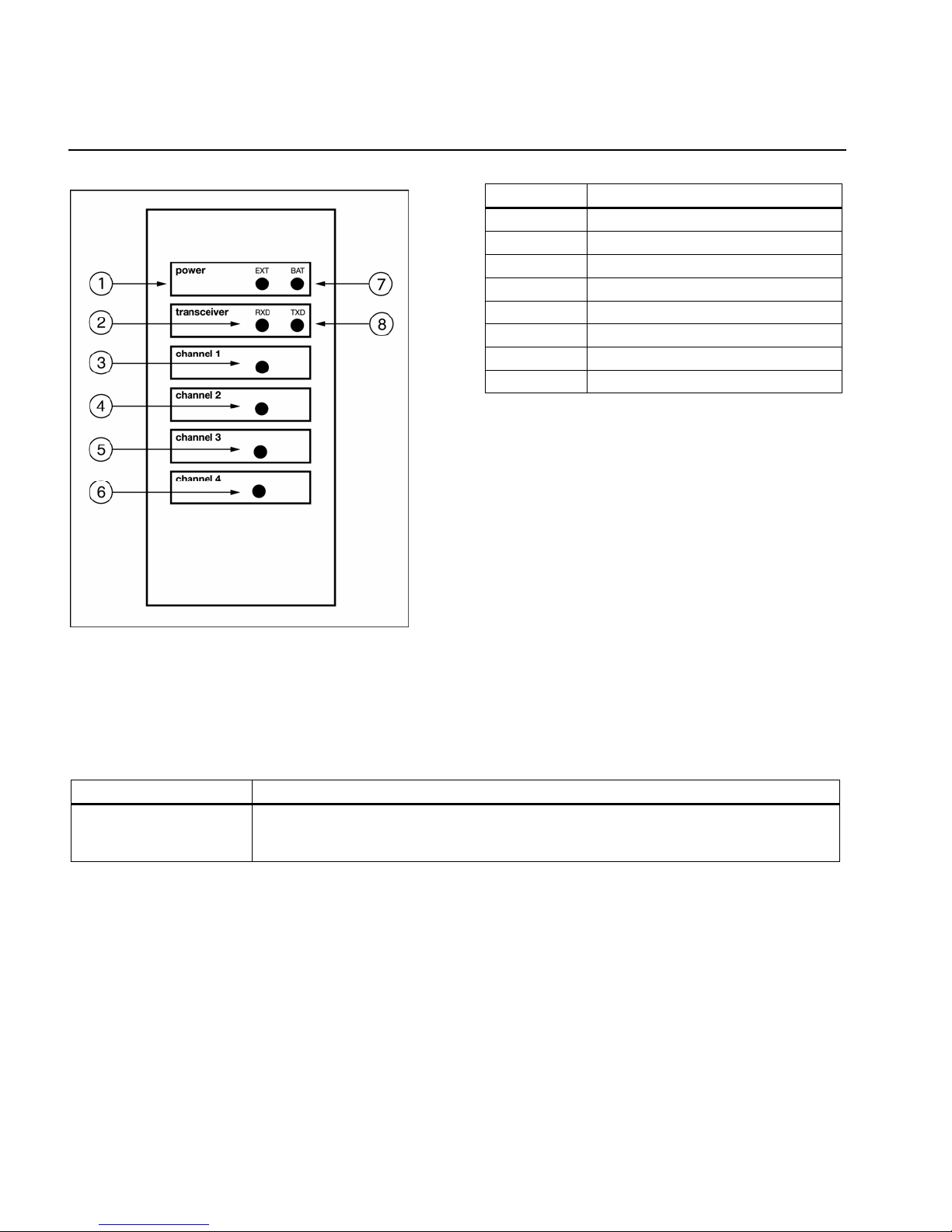
Table 5. LED Indicator
Item Function
1
2
3
4
5
6
7
8
External power LED
Receive mode LED
Designated detector LED
Designated detector LED
Designated detector LED
Designated detector LED
Battery power LED
Transmit mode LED
Figure 4. LED Indicator
Table 6. Switch
Switch Description
POWER
• To activate the remote alarm, toggle the POWER switch to ON.
• To deactivate the remote alarm, toggle the POWER switch to OFF.
4
Page 13

Rig Rat III Remote Alarm
Installation
Installation
Guidelines
a Caution: Qualified personnel should perform the installation according to applicable electrical codes,
regulations, and safety standards.
When installing the remote alarm, adhere to the following guidelines:
• This system is rated for General Purpose Area installation only.
• A circuit breaker is included in the building installation as a disconnect device for the equipment. The circuit breaker is installed
in close proximity to the equipment and is marked as a disconnecting means for the equipment.
• The terminals for all external circuits are only used with equipment that have no live parts that are accessible.
Installation Location
Radio signals transmit well over flat terrain and open water. However, buildings, metal tanks, and other obstructions can interrupt
radio transmissions.
When determining a location for the detector, consider
• the terrain,
• obstructions (such as buildings and metal tanks),
• line-of-sight to the controller antenna (if used with a controller), and
• radio frequency interference (RFI).
When selecting a location to install the remote alarm, do not place it where it can be exposed to electrical shock and/or severe
mechanical shock.
Antenna Installation prior to determining the location for installing the remote alarm.
Read
5
Page 14

Rig Rat III Remote Alarm
User Manual
Mounting the Remote Alarm
Figure 5. Remote Alarm Dimensions
Note: As there are a variety of surfaces where the remote alarm can be mounted, retaining screws are not provided.
Install the remote alarm vertically with the antenna pointing upwards only.
Figure 6. Mounting Requirements
The remote alarm is equipped with pre-drilled mounting flanges for permanent installation. The required minimum/maximum
clearances are as follows:
• Maintain a minimum clearance of 0.38 in. (0.95 cm) below and from each side of the remote alarm.
• Maintain a maximum 65° bend allowance for all cables connected to the remote alarm.
Refer to Figure 5 and Figure 6.
Antenna Location
When determining a location for the antenna, it is important to notice your surroundings. Several factors should be considered when
determining a location for the antenna.
• The terrain,
• clear line-of-sight between the antenna of the controller and the remote alarm,
• clear line-of-sight between the antenna of the detector and the remote alarm, and
• the proximity to any radio frequency interference (RFI).
BW recommends the following when determining a location for the antenna:
• Do not locate the antenna near water.
• Ensure the antenna is as high and clear of surrounding objects as possible.
• The remote alarm’s antenna should be placed as far as possible from other antenna systems to avoid possible RFI.
6
Page 15

Rig Rat III Remote Alarm
Installation
a Warning: Use extreme caution when working near telephone and electrical power lines. Always mount antennas
at least three feet away from power lines.
Note: Atmospheric conditions may cause signal loss.
Antenna Installation
The remote alarm is equipped with a TNC connector for a 5 dBi antenna. Extension cable and higher gain antenna are available
when the antenna needs to be separate from the remote alarm. For transmission distances, refer to
applicable accessory manuals.
Antenna cable lengths must be less than 20 ft./6 m. For greater transmission distances, use a heavier cable such as the LMR 400.
Refer to Replacement Parts and Accessories.
Note: The use of mating connectors to extend cable lengths is not recommended.
Connectors cause signal strength loss
Specifications and any
Wiring
The remote alarm should be powered by a minimum 3 conductor AWG 18 wire with a flexible cord suitable for area use depending
on the local regulatory requirements.
AC power is required to operate the remote alarm. Set the power switch to the applicable voltage.
Note: The remote alarm’s back up batteries trickle charge from the main power.
The battery is for back-up only. The remote alarm should be powered by an AC power source or solar panels.
7
Page 16

Rig Rat III Remote Alarm
User Manual
Setting the Transceiver and Detector Channels
Remote Alarm in Slave Mode
Figure 7. Remote Alarm in Slave Mode
Digitally coded information is received via a 2.4 GHz radio using Frequency Hopping Spread Spectrum (FHS S) technology. Coding
is easily changed on the site to meet changing requirements (e.g., moving alarms, adding detection points, and/or changeover of
equipment).
Complete the following instructions in the order presented to configure the controller, detector, and remote alarm:
1. Configuring the Rig Rat III Controller
a) Deactivate the controller.
b) The controller transceiver receives if the detector channel rotary switch is positioned to channel 0. Confirm the detector
channel is set to 0. Use a slot-regular screwdriver to position the detector channel.
c) The transceiver channel is selected from 00 to 3F (AB combination) and must be identical to the transceiver channel of all
the detectors. Match all detectors transceiver channel codes to the controller’s transceiver channel code.
d) Activate the controller.
8
Page 17

Rig Rat III Remote Alarm
Installation
Table 7. Transceiver and Detector Channel Example
Controller 00 0
Detector 1 00 1
Detector 2 00 2
Detector 3 00 3
Detector 4 00 4
Transceiver
Channel
Detector
Channel
Figure 8. Transceiver
2. Configuring the Rig Rat III Remote Alarm
a) Deactivate the remote alarm.
b) Using a slot-regular screwdriver, position the A and B rotary switches of the receiver channel to the same combination as
the transceiver channel of the controller.
c) Position the Sync Source switch to the OFF position.
d) Activate the remote alarm.
3. Configuring the Rig Rat III Detector
a) Deactivate the detector.
b) Using a slot-regular screwdriver, position the detector’s channel rotary switch to the desired channel. The detector channel
can be selected from 1 to 4. If multiple (maximum of four) detectors are in use, ensure each channel selected is different
from one another.
c) Position the A and B rotary switches of the transceiver channel exactly the same combination as the transceiver channel of
the controller.
d) Activate the detector.
e) Perform a system test for each connected detector. Refer to
System Setup
Detector 1, detector 2, detector 3, and detector 4 are less than 1.8 mi. (3 km) from the remote alarm and controller.
System Test.
The Sync Source switch of the remote alarm must be switched to OFF
9
Page 18

Rig Rat III Remote Alarm
User Manual
Remote Alarm in Master Mode
Figure 9. Remote Alarm in Master Mode
Complete the following instructions in the order presented to configure the controller, detector and remote alarm:
1. Configuring the Rig Rat III Remote Alarm
a) Deactivate the remote alarm.
b) Using a slot-regular screwdriver, position receiver channel A and B rotary switches to any combination ranging from 00 (AB)
to 3F (AB).
c) Position the Sync Source switch to the ON position.
d) Activate the remote alarm.
2. Configuring the Rig Rat III Controller
a) Deactivate the controller.
b) Using a slot-regular screwdriver, position the detector channel rotary switch to F.
c) Position transceiver channel A and B rotary switches to the same combination as the receiver channel of the remote alarm.
d) Activate the controller.
10
Page 19

Rig Rat III Remote Alarm
Operation
3. Configuring the Rig Rat III Detector
a) Deactivate the detector.
b) Using a slot-regular screwdriver, position the detector channel rotary switch to the desired channel. The detector channel
can be selected from 1 to 4. If multiple (maximum of four) detectors are in use, ensure each channel is different from one
another.
c) Position transceiver channel A and B rotary switches to the same combination as the receiver channel of the remote alarm.
d) Perform a system test for each connected detector. Refer to
e) Activate the detector.
System Setup
Detector 1, Detector 2, Detector 3, and Detector 4 are less than 1.8 mi. (3 km) from the remote alarm.
The Sync Source switch of the remote alarm must be positioned to ON.
System Test.
Operation
Activating the Remote Alarm
To activate the remote alarm, open the enclosure and toggle the power switch to ON.
All seven LEDs light green then red. The EXT LED lights green. The RXD LED blinks red and then lights solid green.
LED Display
The remote alarm has seven bi-color LED indicators to display the status of the power source, transceiver, and the detector channel.
Ext: The Ext LED displays the status of the external power source. The external power source can be a solar panel or a DC
charger.
• The Ext LED blinks green when the battery is charging.
• The Ext LED is solid green when the battery is fully charged and trickle charging.
Bat: The Bat LED displays the status of the rechargeable battery.
• The Bat LED is solid red when the battery is fully charged.
• The Bat LED blinks red when the battery is low and requires charging.
• The Bat LED blinks red twice a second when the remote alarm is disabled due to low battery. If an external power source is
connected, the remote alarm remains disabled until the remote alarm is deactivated and then reactivated.
Rxd: The Rxd LED displays the status of the transceiver.
• The Rxd LED blinks red when the transceiver is out of range of the controller or detectors. This occurs when the remote
alarm is in slave mode (Sync Source is OFF).
• The Rxd LED is solid green when the transceiver is in normal operation.
• The Rxd LED blinks orange when the transceiver fails initialization.
11
Page 20

Rig Rat III Remote Alarm
User Manual
Channel 1 to Channel 4: The channel LEDs displays detector status.
The channel LEDs identify which detector is transmitting data or which detector has lost communication with the remote alarm. Loss
of communication with the detector depends on its transmit time interval and loss of transmission time interval. Refer to the Rig Rat
III Detector User Manual.
• The channel LED is solid red when the remote alarm receives a low, high, or fault alarm from the corresponding detector.
• The channel LED is solid orange when the remote alarm loses communication with the corresponding detector.
• The channel LED is unlit when the remote alarm is in standby to receive data from the corresponding detector.
• The channel LED blinks green when the remote alarm receives information from the corresponding detector.
Alarms
If an alarm condition occurs, the strobe and/or siren will not deactivate until the alarm condition no longer exists.
The remote alarm is shipped with all alarm indicators activated.
Setting Alarm Indicators
Siren and strobe indicators can be set for low alarm, high alarm, fault, and RF out.
A low alarm indicates the ambient gas level is above the low alarm setpoint.
A high alarm indicates the ambient gas level is above the high alarm setpoint.
A fault alarm indicates no communication between the detector and alarm because the detector has disconnected from its sensor.
An RF out alarm indicates no communication between the controller and remote alarm.
Figure 10. Alarm
Indicators On
To activate the alarm indicator for a condition, toggle the switch to the ON position. Refer to Figure 10.
To deactivate the alarm indicator for a condition, toggle the switch to the OPEN position. Refer to Figure 11.
Figure 11. Alarm
Indicators Off
Independent Power
The detector and rechargeable option devices use the same low maintenance batteries.
The power options that are provided enable the detector to
• operate from the internal battery, or
• trickle charge the system for maintenance-free operation.
Trickle Charge Options
• Solar power 5, 10, 20, or 30 watt panels
• 24 Vdc direct line power
• Certified line source
12
Page 21

Rig Rat III Remote Alarm
Maintenance
Battery Life
Battery life is also dependant upon the following:
• In a line or solar powered situation, the battery provides the backup in the event of a power interruption.
Battery Level
Refer to LED Display.
Line Power
a Caution: Only qualified personnel should perform power installations. Installations must be performed according
to applicable electrical codes, regulations, and safety standards.
Installation: 24 Vdc direct and AC line power.
The detector and all BW rechargeable option devices can be trickle charged directly using line power (24 Vdc, 115, and 230 Vac).
Charger Power
BW recommends installing a charger: Solar panels or 110/220 Vac or 24 Vdc direct line chargers.
Backup Battery Power
In the event of a main power failure, the remote alarm temporarily runs from the backup battery.
Note: The remote alarm’s backup batteries are trickle charged from the main power.
Backup batteries provide 2-3 hours operating power for a remote alarm.
Maintenance
The remote alarm is designed to provide years of service with regular care and minimal maintenance. At regular intervals, inspect
the instrument and ensure it is operating normally.
System Components: All electronics are sealed in weatherproof enclosures. However, regular maintenance is required for all
system components. Visually inspect and test regularly to ensure optimum performance.
To clean the remote alarm’s exterior, wash it with mild soap and clean water.
Replacing a Fuse
To replace a blown fuse, complete the following steps:
1. Deactivate the remote alarm.
2. Remove the blown fuse with pliers.
3. Install the new fuse.
Replacing a Transceiver
To replace a transceiver, complete the following steps:
1. Deactivate the remote alarm (if applicable).
2. Unplug the cable connecting the transceiver to the circuit board.
3. Unscrew the four screws securing the transceiver to the circuit board.
4. Remove the transceiver by pulling vertically.
13
Page 22

Rig Rat III Remote Alarm
User Manual
5. Insert the new transceiver. Ensure the transceiver’s connectors are aligned with the port.
6. Secure the transceiver to the circuit board with four screws.
7. Attach the cable to the transceiver.
8. Test the system. Refer to
System Test.
Storage and Transporting
BW batteries have a low rate of self discharge. Therefore, the battery powered instruments can be used irregularly or can be stored
for long periods of time.
When storing or transporting battery powered equipment, be aware
• the equipment must be stored in a warm area as freezing the electrolyte damages the battery (as the battery discharges,
the battery freezing point rises),
• the rate of discharge varies with storage temperature,
• higher temperatures result in a faster discharge rate, which reduces the time the equipment can be stored,
• the battery level should not drain below 50% of the fully charged state, and
• the battery will discharge to 50% of its fully charged capacity after one year approximately.
Prior to Storage or Transporting
a Caution: Completely discharged batteries must be charged within 30 days.
Adhere to the following:
• If the battery is completely discharged for a long period of time, cycle charge the unit several times to restore function.
• Ensure the equipment is fully charged before returning to service. Depending upon the conditions, cycle charging may
restore up to 75% of full charge.
• Ensure all instruments are fully charged before storing or transporting.
To prepare equipment for storage or transport, complete the following:
1. Deactivate the required equipment.
2. Create a record of the current connections. This ensures the equipment is reassembled correctly.
3. Disconnect the following from the detector:
• Charger
• Cables
4. Replace the cover cap for the port located on the bottom of the remote alarm.
5. Loosely coil and secure all cables to prevent damage.
14
Page 23

Rig Rat III Remote Alarm
System Test
System Test
A system test is recommended when
• commissioning the remote alarm,
• initially activating the remote alarm,
• moving the remote alarm, or
• modifying the system.
The test ensures the communication path between the controller, remote alarm, and detector(s) is established.
Each connected detector must be tested individually.
Complete the following steps to initiate a system test:
1. Activate the controller and enable all channels (if the controller is part of the system).
2. Activate the remote alarm and wait until the Rxd LED is solid green, indicating normal operation.
3. Activate the detector and wait until the LCD test is complete.
4. Press C XMTR TEST on the detector. The detector’s LCD displays rF tst and counts down from 999 999 to 000 000.
5. Ensure the controller’s LCD is also displaying the countdown. Ensure the remote alarm’s Rxd LED is solid green and the
channel LED of the corresponding detector is flashing green to indicate it is receiving data.
If the detector displays rF Out, the detector is not synchronizing with the controller. The detector may be out of range of the
controller, or the detector’s transceiver channels do not match the controller’s transceiver channels.
If the remote alarm’s Rxd LED blinks red, the remote alarm is not synchronizing with the controller. The remote alarm may be out of
range of the controller or the remote alarm’s transceiver channels do not match the controller’s transceiver channels.
The antenna of the remote alarm and detector must be relocated if they are out of range. Refer to
Antenna Installation.
15
Page 24

Rig Rat III Remote Alarm
User Manual
Troubleshooting
If you encounter a problem, follow the solutions listed in the table below. If you still are unable to correct the problem, contact
BW Technologies by Honeywell.
Table 8. Troubleshooting
Problem Possible Cause Solution
All LEDs are unlit when the remote
alarm is activated.
The battery is depleted and the BAT
LED remains unlit when the external
power source is disconnected and
reconnected.
Channel LED is solid orange.
Blown F2 fuse. Refer to Replace F2 fuse.
Depleted battery. Charge the battery.
Blown F1 fuse. Refer to
The remote alarm’s receiver channel is
different from detector’s transceiver
channel.
Match the receiver channel of the remote
alarm and the transceiver channel of the
detector.
Replace F1 fuse.
RXD LED is continuously blinking red.
RXD LED is continuously blinking
orange.
There is an obstruction between the
detector and the remote alarm.
The remote alarm’s receiver channel is
different from the controller’s transceiver
channel.
There is an obstruction between the
remote alarm and the controller.
The transceiver of the remote alarm is
damaged.
Use the antenna cable to relocate the
antenna of the detector to avoid
obstruction.
Use a high gain antenna.
Match the receiver channel of the remote
alarm and the transceiver channel of the
controller.
Use the antenna cable to relocate the
antenna of the remote alarm to avoid the
obstruction.
Refer to Replace the transceiver.
16
Page 25

Rig Rat III Remote Alarm
Replacement Parts and Accessories
Replacement Parts and Accessories
a Warning
To avoid personal injury or damage to the
remote alarm, use only the specified
replacement parts.
To order parts or accessories listed in the table below,
contact
BW Technologies by Honeywell.
Table 9. Replacement Parts and Accessories
Model No. Description Qty
Additional Replacement Parts and Accessories
RR-RTD-1
RR-FK1
Power Supply Options
SP-U320-S
SP-U330-S
Power Supply Options
Transceiver assembly for Rig
Rat III Remote Alarm
Replacement fuse-500mA for
Rig Rat III Remote Alarm
Stainless steel 20 watt solar
panel
Stainless Steel 30 watt solar
panel
UR-C300 110 Vac single bench charger 1
Power Supply Options
UR-S600
UR-TC10
Weatherproof 110 Vac line
trickle charger
Explosion-proof 110 Vac line
trickle charger
Transmitting Antennas
RR-AN5 Antenna 5 dBi replacement 1
RR-AC50
RR-AC100
LMR 400 antenna cable
assembly (50 ft./ 50 m)
LMR400 antenna cable
assembly (100 ft./ 50 m)
Specifications
Instrument Dimensions: 30.48 x 25.40 x 15.24 cm
(12 x 10 x 6 in.)
Weight:
Enclosure: Fiberglass solid cover type 4x
Operating Temperature: -40°C to +50°C (-40 to +122°F)
Battery backup: -20°C to +50°C (-4°F to +122°F)
Transceiver: -40°C to +80°C (-40°F to +176°F)
Storage Temperature: -20 to +75°C (-40 to +167ºF)
Operating Humidity: 10% to 90% relative humidity
1
(non-condensing)
Certified external power source: Solar panel or DC
8
charger 16V-30 Vdc, minimum 600 mA output current
Transceiver Power Consumption: 150 mA (typical)
1
Transceiver Output Power: 200mW (typical)
Battery: One 12 Ah sealed lead acid battery
1
80 hours in normal operation (no alarm)
70 hours in continuous alarm (siren only)
18 hours in continuous alarm (strobe only)
17 hours in continuous alarm (siren and strobe)
RF Frequency: 2.402 – 2.478 GHz Frequency Hopping
Spread Spectrum (FHSS)
1
1
RF Transmission Distance: 3 km (1.8 miles)
Alarm Conditions: Low alarm, high alarm, fault, and loss of
transmission alarm
Audible Alarm: 112dB siren alarm
1
Visual Alarm: 160,000 candlepower receiver strobe
Altitude: 2000 m
1
Pollution Degree: 2
Installation Category: I
25.00 lb (11.34 kg)
Approved: AC power installations r equire a lim ited circ uit. AC
power should be provided through a fuse that limits the current.
This equipment has been tested and found to comply w i th the limits
for a Class A digital device, pursuant to Part 15 of the FCC Rules and
ICES-003 Canadian EMI requirements. These limits are designed to
provide reasonable protection against harmful interference when the
equipment is operated in a commercial environment. This equipment
generates, uses, and can radiate radio frequency energy and, if not
installed and used in accordance with the instruction manual, may
cause harmful interference to radio communications. Operatio n of
this equipment in a residential area is likely to cause harmful
interference in which case the user will be required to correct the
interference at his own expense.
17
Page 26

Rig Rat III Remote Alarm
User Manual
18
Page 27

 Loading...