

Page 1

1, 2, 3, and 4-Gas Detector
T ec hnical Ref erence Guide
Page 2

Limited Warranty and Limitation Liability
BW Technologies LP (BW) warrants the product to be free from defects in material and workmanship under normal use and service for a period of two years, beginning on the date of
shipment to the buyer. Thi s warranty extends only to t he sale of new and u nused product s to t he original buyer. BW’s warranty obligation is limited, at BW’s option, to re fund of th e purchase
price, repair or replacement of a defective product that is returned to a BW authorized service center within the warranty period. In no event shall BW’s liability hereunder exceed the
purchase price actually paid by the buyer for the Product.
This warranty does not include:
a) fuses, disposable batteries or the routine replacement of parts due to the normal wear and tear of the product arising from use;
b) any product which in BW’s opinion, has been misused, altered, neglected or damaged, by accident or abnormal conditions of operation, handling or use;
c) any damage or defects attributable to repair of the product by any person other than an authorized dealer, or the installation of unapproved parts on the product; or
The obligations set forth in this warranty are conditional on:
a) proper storage, installation, calibration, use, ma intenance and compliance with the product manual instructions and any other applicable recommendations of BW;
b) the buyer promptly notifying BW of any defect and, if required, promptly making the product available for correction. No goods shall be returned to BW until receipt by the buyer of
shipping instructions from BW; and
c) the right of BW to require that the buyer provide proof of purchase such as the original invoice, bill of sale or packing slip to establish that the product is within the warranty period.
THE BUYER AGREES THAT THIS WARRANTY IS THE BUYER’S SOLE AND EXCLUSIVE REMEDY AND IS IN LIEU OF ALL OTHER WARRANTIES, EXPRESS OR IMPLIED, INCLUDING BUT NOT LIMITED TO ANY
IMPLIED WARRANTY OF MERCHANTABILITY OR FITNESS FOR A PARTICULAR PURPOSE. BW SHALL NOT BE LIABLE FOR ANY SPECIAL, INDIRECT, INCIDENTAL, OR BASED ON CONTRACT, TORT OR RELIANCE
OR ANY OTHER THEORY.
Since some countries or states do not allow limitation of the term of an implied warranty, or exclusion or limitation of incidental or consequential damages, the limitations and exclusions of
this warranty may not apply to every buyer. If any provision of this warr anty is held invalid or unenforceable by a court of competent jurisdiction, such holding will not affect the validity or
enforceability of any other provision.
BW Technologies by Honeywell BW Technologies by Honeywell BW Technologies by Honeywell
Corporate Headquarters America Europe
2840 - 2nd Ave. SE 3279 West Pioneer Parkway 5 Canada Close
Calgary, AB Arlington, TX Banbury, Oxfordshire
Canada T2A 7X9 USA 76013 United Kingdom OX16 2RT
Page 3

Table of Contents
Title Page
Limited Warranty and Limitation Liability ........................................................................................................................ 0
Contacting BW Technologies by Honeywell.................................................................................................................... 1
Introduction......................................................................................................................................................................... 1
Gases Monitored ..................................................... .... ... ... ... ... .... ... ................................................................................. 2
Safety Information - Read First.......................................................................................................................................... 2
Sensor Poisons and Contaminants .................................................................................................................................. 6
Getting Started.................................................................................................................................................................... 7
Parts of the GasAlertQuattro ............................................................................................................................................. 8
Screen Elements................................................... ... ....................................... ... ... .............................................................. 9
Activating/Deactivating the Detector .............................................................................................................................. 11
Startup Sequence ............................................................................................................................................................. 11
Battery Test ................................................................................................................................................................... 11
Segment Test ....................................................... ... .... ... ... ....................................... ... ... ............................................... 11
Product Identification and Firmware Revision ............................................................................................................... 11
Startup Message............................................................................................................................................................ 12
Alarm Setpoints ............................................................................................................................................................. 12
Sensor Self Test............................................................................................................................................................ 13
Auto Zero Sensors................... ... ....................................... ... ... .... ...................................... ............................................ 14
Next Calibration Due................ ... ....................................... ... ... ....................................... ... ............................................ 14
Sensors Due for Calibration ..................................................................................................................................... 15
Bump Test Due.............................................................................................................................................................. 15
Sensors Due for Bump Test ..................................................................................................................................... 16
Startup Self-test Summary............................................................................................................................................. 17
i
Page 4

GasAlertQuattro
Technical Reference Guide
Title Page
Installing Fleet Manager II ................................................................................................................................................18
Using Fleet Manager II to Configure the Detector ......................................................................................................... 18
Device Configuration......................................... ... ... ... ....................................... ... .... ........................................................19
Serial Number Field .......................................................................................................................................................20
Firmware Version........... .... ... ... ... ....................................... ... ... ....................................... ............................................... 20
Hardware Version ....... ... ....................................... ... .... ...................................... .... ... .....................................................20
Startup Message......... ... .... ... ... ....................................... ... ... ....................................... ... ............................................... 21
Lockout on Self-Test Error............................................................................................................................................. 21
Safe Mode...................................................................................................................................................................... 21
Confidence/Compliance Beep .......................................................................................................................................21
Latching Alarms .............................................................................................................................................................22
Force Calibration............................................................................................................................................................22
Force Bump ................................................................................................................................................................... 23
Cal IR Lock ..................................................... ... ... ... ....................................... ... .... ........................................................24
Flip Display .................................................................................................................................................................... 24
Stealth............................................................................................................................................................................ 25
Datalog Interval........... ... ....................................... ... .... ... ....................................... ... ... .................................................. 25
IntelliFlash Interval...................................... .... ... ... ....................................... ... ... ............................................................26
Confidence/Compliance Beep Interval...........................................................................................................................26
Language ...........................................................................................................................................................................26
Sensor Configuration ....................................................................................................................................................... 27
Sensor Disabled.............................................................................................................................................................27
Calibration Gas (ppm).............. ......................................................................................................................................28
Calibration Interval...................................... .... ... ... ... .... ... ... ....................................... ... ... ............................................... 29
Bump Interval................. ....................................... ... .... ...................................... .... ... .....................................................29
Low Alarm......................................................................................................................................................................29
High Alarm .....................................................................................................................................................................29
ii
Page 5

GasAlertQuattro
Technical Reference Guide
Title Page
TWA Alarm........ .... ...................................... .... ... ....................................... ... ... ...............................................................29
STEL Alarm.................................................................................................................................................................... 30
Correction Factor (LEL) .................................................................................................................................................30
STEL Interval ................................................................................................................................................................. 30
TWA Period (hours) ........... ...................................... .... ... ....................................... ... ... ..................................................31
TWA Method......................................... ... ... .... ...................................... .... ... ..................................................................31
50% LEL = (%CH4)........................................................................................................................................................31
Auto Zero on Startup......................................................................................................................................................31
LEL by Volume CH4 ......................................................................................................................................................31
10% LEL (of reading) Over-span ...................................................................................................................................32
20.8 Base Reading ........................................................................................................................................................32
Low Alarm Acknowledge................................................................................................................................................32
Alarms................................................................................................................................................................................33
Stopping a Gas Alarm....................................................................................................................................................36
Computed Gas Exposures ...............................................................................................................................................36
Viewing and Clearing Gas Exposures ........................................................................................................................... 37
Gas Alarm Setpoints...................................................................................................................................................... 39
Sample Gas Alarm Setpoints.........................................................................................................................................39
Bump Test....... ... ... .... ...................................... .... ... ....................................... ... ... ...............................................................40
Bump Test Logging............... ... ... ... .... ...................................... .... ... ............................................................................... 40
Performing a Bump Test................................................................................................................................................40
Calibration .........................................................................................................................................................................43
Guidelines......................................................................................................................................................................43
Connecting the Gas Cylinder to the Detector ................................................................................................................ 44
Calibration Procedures ................................................ ... ... ... ... .... ... ............................................................................... 45
Single Gas Calibration........................................ .... ... ... ....................................... ... ... ............................................... 45
Quad Gas Calibration ............................................................................................................................................... 45
iii
Page 6

GasAlertQuattro
Technical Reference Guide
Title Page
Zero Sensor.............................................................................................................................................................. 47
Apply Calibration Gas...............................................................................................................................................47
Days to Next Calibration...........................................................................................................................................49
Calibrating Using an IR Device...................................................................................................................................... 50
IR Link With Fleet Manager II ...................................................................................................................................50
Event Logs.........................................................................................................................................................................52
Datalogs.............................................................................................................................................................................52
Bump and Calibration Results.........................................................................................................................................53
Downloading Datalogs and Event Logs.........................................................................................................................54
Software Requirements .................................................................................................................................................55
Maintenance ...................................................................................................................................................................... 55
Battery Charging and Maintenance Cautions ................................................................. ... .... ... .....................................55
Charging the Rechargeable Battery...............................................................................................................................56
Optimum Battery Operation...................................................................................................................................... 58
Rechargeable Battery Capacity.............................. ... ... ... ....................................... ... ... ............................................ 58
Replacing the Battery Pack............................................................................................................................................ 58
Battery Pack Retaining Screw ..................................................................................................................................58
Replacing the Alkaline Batteries ....................................................................................................................................59
Replacing the Sensors...................................................................................................................................................62
Replacing the Sensor Filter............................................................................................................................................64
Troubleshooting................................................................................................................................................................ 65
Startup Troubleshooting. .... ...................................... .... ... ....................................... ... ... ..................................................70
Calibration Troubleshooting..................................... .... ... ... ....................................... ... ... ...............................................72
Bump Test Troubleshooting............... ... ... ... .... ...................................... .... ... ..................................................................72
Replacement Parts and Accessories .............................................................................................................................. 73
Specifications.................................................................................................................................................................... 75
General Datalog Specifications......................................................................................................................................77
iv
Page 7

List of Figures
Figure Title Page
1. Parts of the GasAlertQuattro................................................................................................................................. 8
2. Connecting the IR Link............................................ ... ... .... ... ... ... .... ..................................................................... 18
3. Device Configuration via IR Link ......................................................................................................................... 19
4. Device Configuration via MicroDock II................................................................................................................. 20
5. Sensor Configuration Tab (CO) via MicroDock II................................................................................................ 27
6. Sensor Configuration Tab (CO) via IR Link......................................................................................................... 27
7. Sensor Configuration Tab (H
8. Bump Test Installation......................................................................................................................................... 41
9. Tightening the Calibration Cap............................................................................................................................ 42
10. Calibration Cap Installation ................................................................................................................................. 44
11. Connecting the Gas Cylinder to the Detector...................................................................................................... 45
12. Attaching the Calibration Cap.............................................................................................................................. 47
13. Enter Password Dialog Box................................................................................................................................. 50
14. Device Selection Popup ...................................................................................................................................... 50
15. Calibrate Device Dialog Box................................................................................................................................ 51
16. Connecting the Charger Adapter...... ....................................... ... ....................................... ... .... ........................... 56
17. Screwdriver ......................................................................................................................................................... 58
18. Removing the Battery Pack.............. ....................................... ... .... ...................................... ............................... 59
19. Ejector Bar Unhooked from Release Clasp......................................................................................................... 60
20. Using the Tab to Pull on the Ejector Bar ............................................................................................................. 60
21. Pulling up on the Ejector Bar............................................................................................................................... 61
22. Inserting the Alkaline Batteries............................................................................................................................ 61
23. Replacing a Sensor or Sensor Filter ................................................................................................................... 63
S) via MicroDock II............................................................................................... 28
2
v
Page 8

Fleet Manager II
Operator’s Manual
24. Replacing the Sensor Filter ................................................................................................................................. 64
25. Inserting the Sensor Filter Correctly....................................................................................................................64
vi
Page 9

List of Tables
Table Title Page
1. Gases Monitored........................................... .... ...................................... .... ... ....................................................... 2
2. International Symbols.............. ... ... ... .... ... .............................................................................................................. 5
3. Sensor Poisons and Contaminants....................................................................................................................... 6
4. Parts of the GasAlertQuattro................................................................................................................................. 8
5. Pushbutton .......................................................................................................................................................... 10
6. Connecting the IR Link............................................ ... ... .... ... ... ... .... ..................................................................... 18
7. Alarms ................................................................................................................................................................. 33
8. Computed Gas Exposures ............ ....... ... ... ... ...................................................................................................... 36
9. Gas Alarm Setpoints ..................................................... .... ... ... ... ....................................... .................................. 39
10. Sample Factory Alarm Setpoints.......... ... ....................................... ... ... ............................................................... 39
11. Bump Test Installation......................................................................................................................................... 41
12. Datalog Frequency.............................................................................................................................................. 52
13. Connecting the Charger Adapter...... ....................................... ... ....................................... ... .... ........................... 57
14. Troubleshooting................................................................................................................................................... 65
15. Startup Troubleshooting...................................................................................................................................... 70
16. Calibration Troubleshooting ................................................................................................................................ 72
17. Replacement Parts and Accessories .................................................................................................................. 73
vii
Page 10

Fleet Manager II
Operator’s Manual
viii
Page 11

GasAlertQuattro
Contacting BW Technologies by Honeywell
To contact BW Technologi es by Ho ne y we ll , ca l l
USA: 1-888-749-8878
Canada: 1-800-663-4164
Europe: +44 (0) 1295 700300
Other countries: +1-403-248-9226
Address correspondence to
BW Technologies by Honeywell
2840 – 2 Avenue S.E.
Calgary, AB T2A 7X9
CANADA
Email: info@gasmonitors.com
Website: www.gasmonitors.com
ISO 9001
Introduction
a Warning
To ensure personal safety, read Safety Information -
Read First and a Cautions before using the detector.
The GasAlertQuattro gas detector (“the detector”) warns of hazardous
gas at levels above user-defined alarm setpoints.
The detector is a personal safety device. It is your responsibility to
respond properly to the alarm.
1
Page 12

GasAlertQuattro
Technical Reference Guide
Gases Monitored
The following table lists the gases that are monitored by the detector.
Table 1. Gases Monitored
Gas Detected Unit of Measure
Hydrogen sulfide (H2S)
Carbon monoxide (CO) parts per million (ppm)
Combustible gases (LEL)
Oxygen (O
CAUTION: FOR SAFETY REASONS, THIS EQUIPMENT MUST BE
OPERATED AND SERVICED BY QUALIFIED PERSONNEL ONLY.
READ AND UNDERSTAND THIS TECHNICAL REFERENCE GUIDE
COMPLETELY BEFORE OPERATING AND SERVICING.
)
2
parts per million (ppm)
a) percent of lower explosive limit
(%LEL)
b) percent by volume methane
0-5.0% v/v
% volume
Safety Information - Read First
Use the detector only as specified in this technical reference guide
and the operator’s manual, otherwise the protection provided by the
detector may be impaired.
International symbols used on the detector and in this technic al
reference guide are define d in Table 2.
Read the a Cautions on the following pages before using the detector.
ec Warning
This instrument contains a lithium polymer bat te ry.
Dispose of lithium cells immediately. Do not
disassemble and do not dispose of in fire. Do not mix
with the solid waste stream. Spent batteries must be
disposed of by a qualified recycler or hazar dous
materials handler.
2
Page 13

a Cautions
• Warning: Substitution of components may impair Intrinsic Safety.
GasAlertQuattro
Safety Information - Read First
• Before using the detector, refer to Sensor Poiso ns and Contaminants
• Caution: For safety reasons, this equipment must be operated and serviced by qualified personnel only. Read and
understand this technical reference guide completely before operating or servicing.
• Do not use the detector if it is damaged. Inspect the detector before using. Look for cracks and/or missing parts.
• If the detector is damaged or parts are missing, contact BW Technologies by Honeywell
• Only use sensor(s) that are specifically designed for the GasAlertQuattro. Refer to Replacement Parts and
Accessories.
• Calibrate the detector before first-time use and then on a regular schedule, depending on use and sensor exposure to
poisons and contaminants. BW Technologies by Honeywell recommends that the sensors be calibrated regularly and
at least once every 180 days (6 months).
• BW recommends to bump test the sensors before each day’s use to confirm their ability to respond to gas by
exposing the detector to a gas concentration that exceeds the alarm setpoints. Manually verify that the audible and
visual alarms activate. Calibrate if the readings are not within the specified limits.
• Protect the combustible sensor from exposure to lead compounds, silicones, and chlorinated hydrocarbons.
Although certain organic vapors (such as leaded gasoline and halogenated hydrocarbons) may temporarily inhibit
sensor performance, in most cases the sensor will recover after calibration.
• BW recommends the combustible sensor be checked with a known concentration of calibration gas after any known
exposure to catalyst contaminants/poisons (sulfur compounds, silicone vapors, halogenated compounds, etc).
• The combustible sensor is factory calibrated to 50% LEL methane. If monitoring a different combustible gas in the
% LEL range, calibrate the sensor using the appropriate gas.
• Warning: High off-scale LEL readings may indicate an explosive concentration.
.
immediately.
3
Page 14

GasAlertQuattro
Technical Reference Guide
• Only the combustible gas detection portion of this instrument has been assessed for performance by CSA
International.
• For use only in potentially explosive atmospheres where oxygen concentrations do not exceed 20.9% (v/v).
• Any rapid upscaling reading followed by a declining or erratic reading may indicate a gas concentration beyond upper
scale limit, which may be hazardous.
• Calibrate only in a safe area that is free of hazardous gas in an atmosphere of 20.9% oxygen.
a Cautions
• Use only BW approved batteries for the GasAlertQuattro detector. Refer to Specifications
• Charge the detector before first-time use. BW recommends the detector be charged after every workday.
• Charge the GasAlertQuattro using BW charger adapters designed for the GasAlertQuattro only. Do not use any other
charging adapter. Failure to adhere to this caution can lead to fire and/or explosion.
• Extended exposure of the GasAlertQuattro to certain concentrations of combustible gases and air may stress a
detector element, which can seriously affect its performance. If an alarm occurs due to high concentrations of
combustible gases, recalibration should be performed, or if needed, the sensor replaced.
• Do not test the combustible sensor’s response with a butane cigarette lighter; doing so will damage the sensor.
• Do not expose the detector to electrical shock or severe continuous mechanical shock.
• Deactivating the detector by removing the battery pack may cause improper operation and harm the detector.
• Do not immerse the detector in liquids.
• Do not attempt to disassemble, adjust, or service the detector unless instructions for that procedure are provided in
this technical reference guide and/or that p art is listed as a replacement p art. Use only BW Technologies by Honeywell
Replacement Parts and Accessories
.
.
4
Page 15
GasAlertQuattro
Safety Information - Read First
a Cautions
• Warning: The lithium battery (QT-BAT-R01) may present a risk of fire or chemical burn hazard if misused. Do not
disassemble, heat above 212°F (100°C), or incinerate.
• Warning: Do not use any other lithium batteries with the GasAlertQuattro detector. Use of any other cell can cause fire
and/or explosion. To order and replace the QT-BAT-R01 battery, refer to Replacement Parts and Accessories.
• Warning: Lithium polymer cells exposed to heat at 266°F (130°C) for 10 minutes can cause fire and/or explosion.
• Dispose of used lithium cells immediately. Do not disassemble and do not dispose of in fire. Do not mix with the solid
waste stream. Spent batteries must be disposed of by a qualified recycler or hazardous materials handler.
• Keep lithium cells away from children.
• Calibration cylinders that are used with a demand flow regulator must meet the following maximum inlet pressure
specifications:
• Disposable cylinders 0-1000 psig/70 bar
• Refillable cylinders 0-3000 psig/270 bar
• If using the detector near it s upper o r lower oper ating te mperature, BW recommends zeroi ng or acti vating the detector
in that environment.
Table 2. International Symbols
Symbol Meaning Symbol Meaning
International Electrotechnical Commission
n
Approved to both U.S. and Canadian Standards by CSA International
IECEx
Scheme for Certification to Standards for
Electrical Equipment for Explosive Atmospheres
g
X
European Explosives Protection Conforms to Inmetro
Conforms to European Union Directives
ATEX
Conforms to European ATEX Directives
5
Page 16

GasAlertQuattro
Technical Reference Guide
Sensor Poisons and Contaminants
Several cleaners, solvents, and lubricants can contaminate and cause
permanent damage to sensors. Before using cleaners, solvents, and
lubricants in close proximity to the detector sensors, read the following
caution and refer to Table 3.
a Caution
Use only the following BW Technologies by Honeywell
recommended products and pr ocedures:
• Use water-based cleaners.
• Use non-alcohol based cleaners.
• Clean the exterior of the detector with a soft,
damp cloth.
• Do not use soaps, polishes, or solvents.
The following table lists common products to avoid using around
sensors.
Table 3. Sensor Poisons and Contaminants
Cleaners and
Lubricants
Brake cleaners Silicone cleaners
Lubricants Silicone based
Rust inhibitors Hand/body and
Window and glass
cleaners
Dishsoaps Mold releasing
Citrus based cleaners Polishes
Alcohol based
cleaners
Hand sanitizers
Anionic detergents
Methanol
(fuels and antifreezes)
Silicones Aerosols
Bug repellents
and protectants
adhesives, sealants, and gels
medicinal creams
that contain silicone
Tissues containing
silicone
agents
and sprays
Lubricants
Rust inhibitors
Window and
glass cleaners
6
Page 17

GasAlertQuattro
Getting Started
Getting Started
The list below provides the standard ite ms included with the detector.
If the detector is damaged or parts are missing, contact the place of
purchase immediately.
• Sensors: H
(depending upon sensors ordered with detector)
Detectors that are configured for 1, 2, or 3 gases may contain a
dummy sensor in one of the four sensor locations.
• Calibration cap
• Calibration hose (3 ft./1 m) w/ quick connect
• Charging adapter or 3 alkaline batteries (dependent on type of battery pack)
• Screwdriver
• Operator’s manual
• Supplementary booklet including a quick reference card
• Technical reference guide on CD-ROM
For a list of GasAlertQuattro accessories, refer to Replacement Parts
and Accessories.
Fleet Manager II Options
Fleet Manager II software can be downloaded without cost from BW
Technologies by Honeywell’s website www.gasmonitors.com
Fleet Manager II CD-ROM is shipped with the MicroDock II base station.
S, CO, O2, and combustible LEL
2
Note
.
The detector is shipped with the sensors and a rechargeable or alkaline
battery pack. To replace sensors and maintain the battery pack, refer
to the following:
Replacing the Sensors
•
• Charging the Rechargeable Battery
• Replacing the Battery Pack
• Replacing the Alkaline Batteries
To order parts, refer to Replacement Parts and Accessories.
To become oriented with the features and functi ons of the det ector, refer
to the following figures and tables:
• Figure 1.
• Screen Elements
• Table 5.
and Table 4. describes the detector’s components.
describes the LCD icons and screen elements.
describes the detector’s pushbutton.
7
Page 18
GasAlertQuattro
Technical Reference Guide
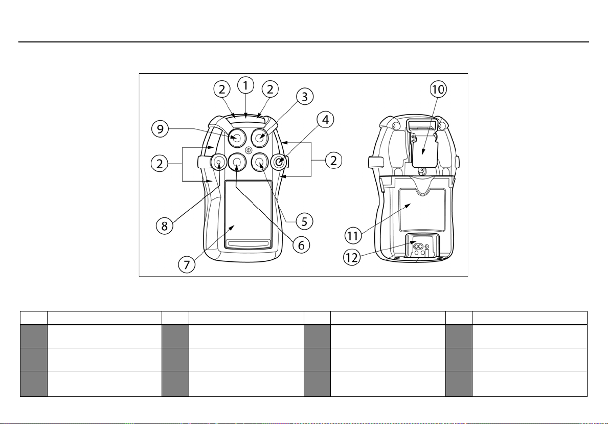
Parts of the GasAlertQuattro
Figure 1. Parts of the GasAlertQuattro
Table 4. Parts of the GasAlertQuattro
Item Description Item Description Item Description Item Description
1 IntelliFlash (green LED) 4 Pushbutton 7
Visual alarm indicator (red
2
LED)
Hydrogen sulfide (H
3
sensor
S)
2
5 Combustible (LEL) sensor 8 Audio alarm 11 Bat tery pack
Carbon monoxide (CO)
6
sensor
8
Liquid crystal display
(LCD)
Oxygen (O
9
10 Alligator clip
)
2
Charging connector and
12
IR interface
Page 19
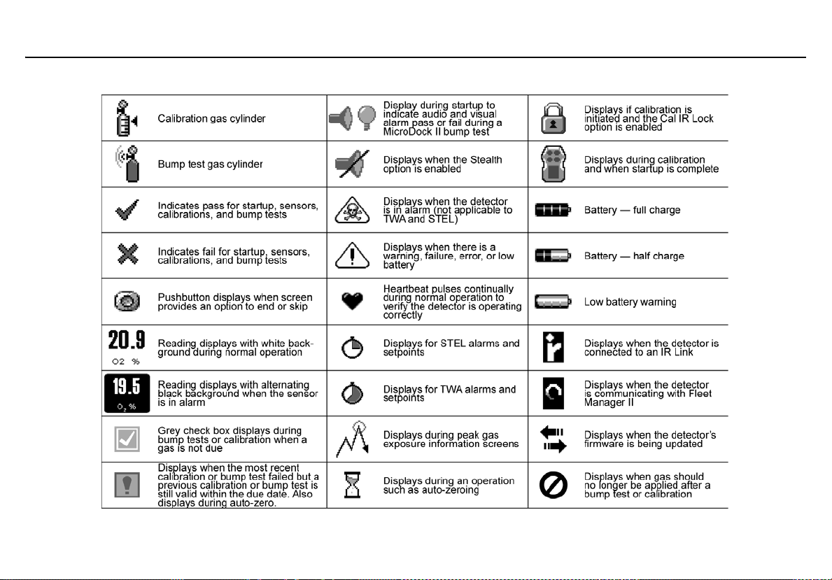
Screen Elements
GasAlertQuattro
Screen Elements
9
Page 20

GasAlertQuattro
Technical Reference Guide
Table 5. Pushbutton
Pushbutton Description
• To activate the detector, press and hold C in a safe area that is free of hazardous gas and in an atmosphere of 20.9% oxygen.
• To deactivate the detector, press and hold C during the powering off countdown. Release C when OFF
displays.
• To view the date/time, current battery power, calibration due date, bump test due date, TWA, STEL, and
peak readings, press C twice rapidly. To clear the TWA, STEL, and peak readings, press and hold C
when the LCD displays Hold C to reset peaks, TWA, STEL.
• To initiate calibration, press and hold C while the detector performs the OFF countdown. Continue holding
C
C while the LCD briefly deactivates and then reactivates to begin the calibration countdown. Release C
when Calibration started displays.
• To activate the backlight, press C and release.
• To acknowledge latching alarms, press C.
• To acknowledge a low alarm and temporarily disable the audible alarm, press C. The Low Alarm
Acknowledge option must be enabled in Fleet Manager II.
10
• To acknowledge any of the “due today” messages (calibration and bump test), press C. If the force calibration option is enabled, a calibration cannot be bypassed. If the force bump option is enabled, a bump test
cannot be enabled.
Page 21
GasAlertQuattro
Activating/Deactivating the Detector
Activating/Deactivating the Detector
a Caution
Only activate the detector in a safe area that is free of
hazardous gas in an atmosphere of 20.9% oxygen.
Activate: Press and hold C.
Deactivate: Press and hold C during the powering off countdown.
Release C when OFF displays.
Startup Sequence
If an error screen displays during the startup sequence, refer to Startup
Troubleshooting.
When the detector is activated, it performs several tests during th e
startup sequence. Confirm the following tests occur.
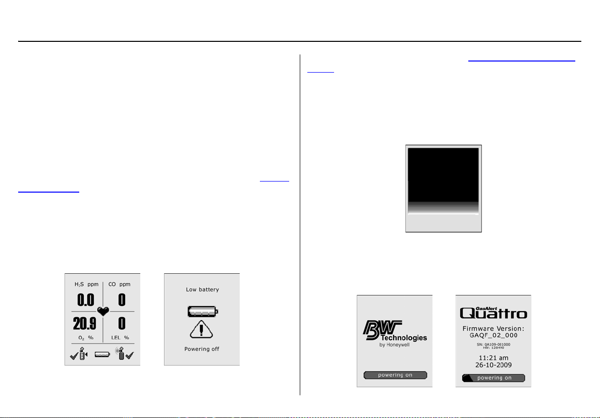
Battery Test
If battery power is critically low upon startup, th e detector displays the
following screens and then deactivates.
Recharge the battery for 6 hours. Refer to Charging the Rechargeable
Battery.
Segment Test
1. The segment test verifies that the visual, audio, and
vibrate functions are operating correctly. The detector
alarms, vibrates, and displays the following screen.
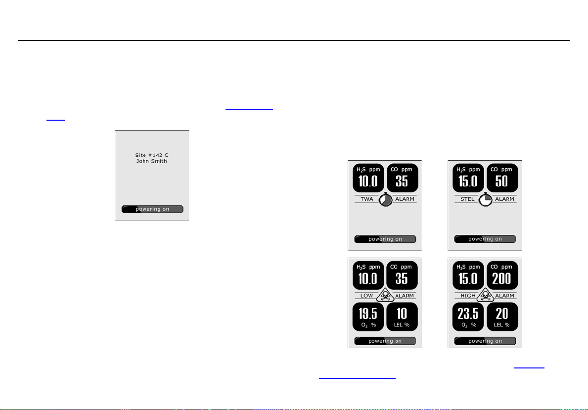
Product Identification and Firmware Revi si on
2. The following two screens displ ay showing the BW and product
identification, and the firmware revision.
11
Page 22
GasAlertQuattro
Technical Reference Guide
Startup Message
3. If data is entered in the Startup Message field in Fleet Manager II, a startup message (50 characters maximum) displays
on the LCD. If a startup message has not been entered, it is
bypassed during the startup sequence. Re fer to Startup Mes-
sage in User Options.
Note
To make a line break to force text to the next line, as in the
example above, press the
| (pipe or vertical bar) key.
Alarm Setpoints
4. The alarm setpoints defined in Fleet Manager II display on the
detector in the following order:
• TWA (time-weighted average) CO and H
• STEL (short-term exposure limit) CO and H
• Low
•High
S only
2
2
S only
12
Note: Alarm setpoints may vary by region. Refer to Sample
Gas Alarm Setpoints.
Page 23
GasAlertQuattro
Startup Sequence
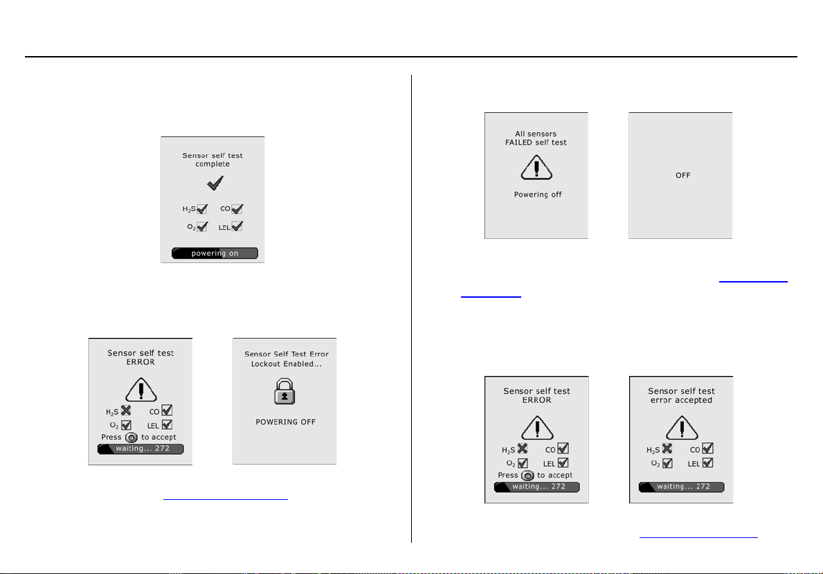
Sensor Self Test
The detector tests the sensors during startup. If all sensors pass, the
following screen displays.
Lockout Enabled
If Lockout on Self-test Error is enabled and a sens or fails the
startup sensor self-test, the following screens display.
OFF then displays and the detector deactivates. For all sensor and selftest error screens, refer to Startup Troubleshooting
.
If all sensors fail the startup sensor self-test, the following
screens display.
The detector then automatically deactivates.
For all sensor and self-test error screens, refer to Startup Trou-
bleshooting.
Lockout Disabled
If Lockout on Self Test Error is disabled and a sensor fails
the self-test, the following screens display.
BW Technologies by Honeywell recommends that the sensor
be replaced immediately. Refer to Replacing the Sensors
.
13
Page 24
GasAlertQuattro
Technical Reference Guide
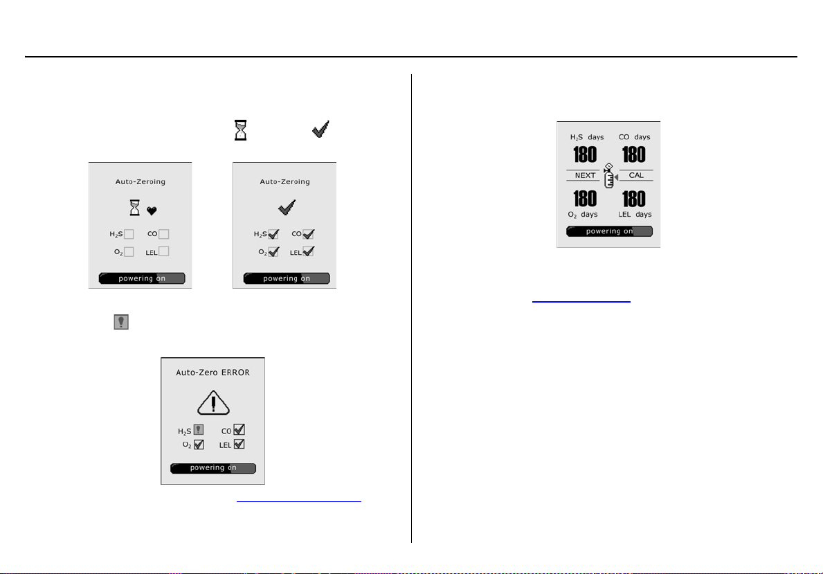
Auto Zero Sensors
5. The detector zeros the sensors.
When auto-zeroing is complete, changes to .
If a sensor fails the auto-zero test, the Auto-zero error screen
displays. indicates which sensor failed and that a previous
auto-zero result for that sensor will be used to zero the sensor.
Next Calibration Due
6. The next calibration due date for each sensor displays.
Note
N/A displays when the calibration interval has been defined as
0 days. Refer to Calibration Interval
a Warning
BW Technol ogies by Honeywell recommends that the
sensors be calibrated regularly and at least once every
180 days (6 months).
.
For sensor error causes, refer to Startup Troubleshooting
14
.
Page 25
GasAlertQuattro
Startup Sequence
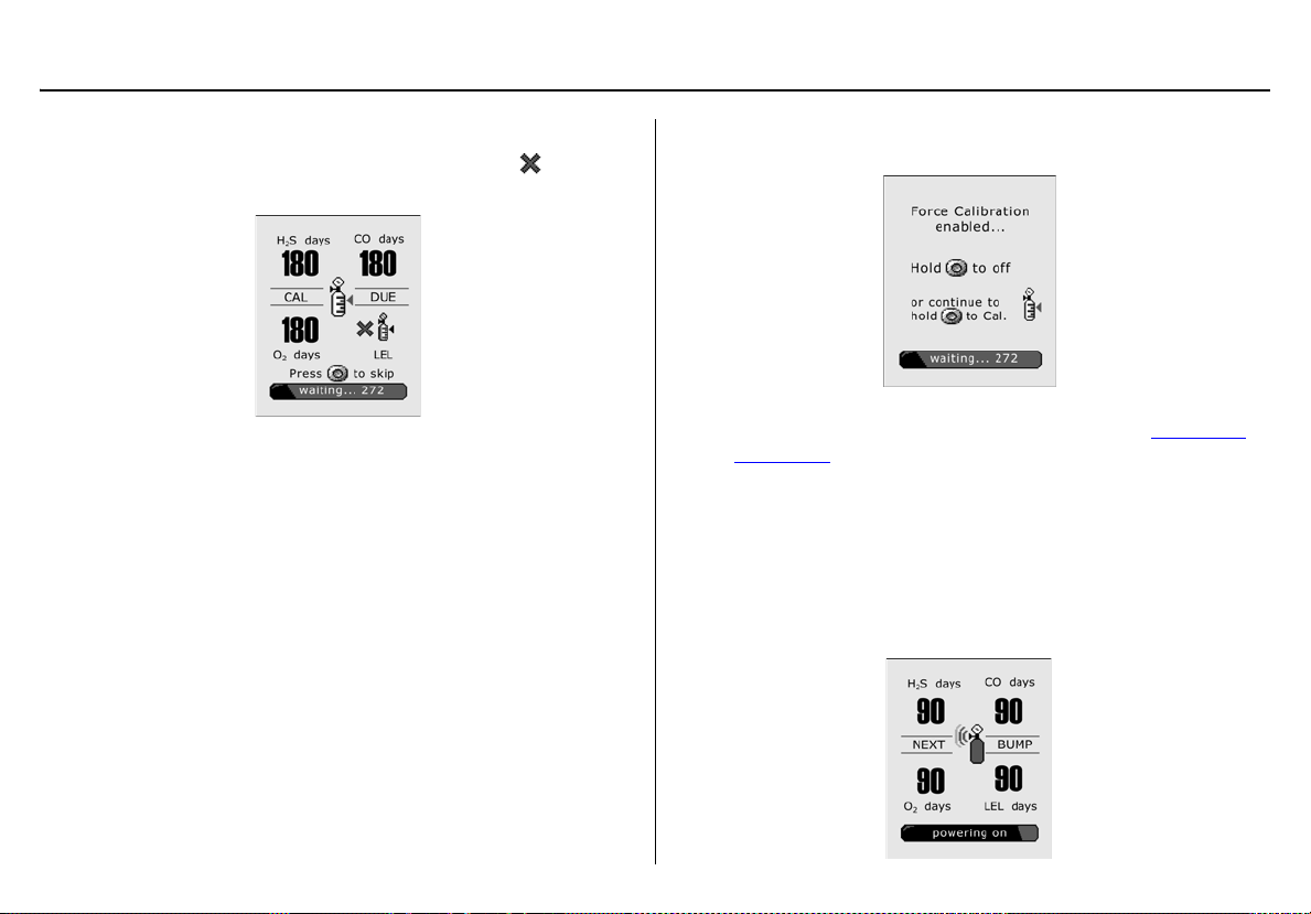
Sensors Due for Calibration
If calibration is due, the following screen displays. flashes
for each sensor that is due for calibration.
Press C to acknowledge that calibration is due. If Force Cali-
bration is disabled, the detector enters normal operation.
If the Force Calibration option is enabled, the following
screen displays.
The sensor(s) must be calibrated to enter normal operation.
Press and hold C to enter calibration and refer to Calibration
Procedures, or press C and release to deactivate the detector.
Note
BW Technologies by Honeywell recommends that the sensors
be calibrated at least once every 180 days (6 months).
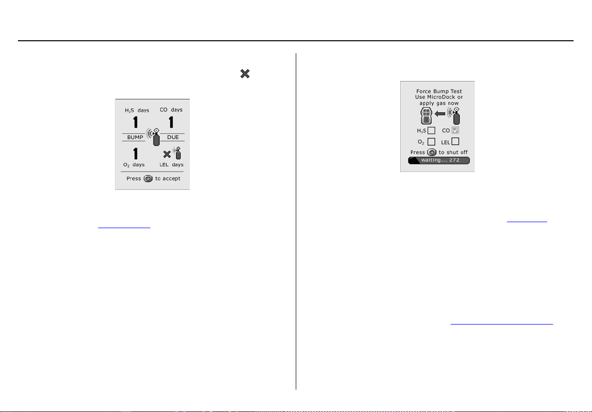
Bump Test Due
7. The next bump test due date for each sensor displays.
15
Page 26
GasAlertQuattro
Technical Reference Guide
Sensors Due for Bump Test
If a bump test is due, the following sc reen displays. flashes
for each sensor that is due for a bump test.
Note
N/A displays when the bump test interval has been defined as
0 days. Refer to Bump Interval
BW recommends to bump test the sensors before each
day’s use to confirm their ability to respond to gas by
exposing the sensors to a gas concentration that
exceeds the alarm setpoints.
Press C to acknowledge that a bump test is due. If Force
Bump is disabled, the detector enters normal operation.
.
a Caution
Force Bump Test Enabled: If the Force Bump option is
enabled, the following screen displays.
The sensor(s) must pass the bump test to enter normal operation.
Apply gas manually or via the MicroDock II station, or press
C to exit and deactivate the detector. Refer to Bump Test
Note
BW Technologies by Honeywell recommends to bump test the
sensors before each day’s use to confirm their ability to
respond to gas by exposing the sensors to a gas concentration
that exceeds the alarm setpoints. Manually verify that the audible and visual alarms activate. Calibrate if the readings are not
within the specified limits.
If error screens display, refer to Bump Test Troubleshooting
.
.
16
Page 27
GasAlertQuattro
Startup Sequence
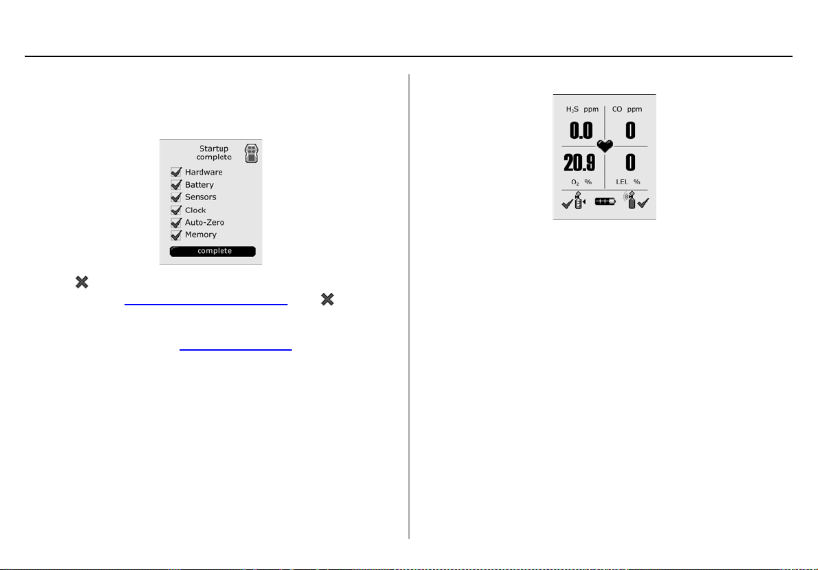
Startup Self-test Summary
8. The detector performs several diagnostic tests during startup
to ensure it is operating correctly. A checkmark displays for
each test that has passed successfully.
If displays for Hardware, Battery, Sensors, Clock, or Memory contact BW Technologies by Honeywell
Auto-Zero, the detector uses the pervious zero readings. The
detector can be zeroed in a safe area free of hazardous gas.
Refer to steps #1-9 in Quad Gas Calibration
. If an displays
.
The detector enters normal operation.
The detector automatically begins
• recording the peak gas exposure,
• calculating the short-term exposure level (STEL), and
• calculating the time-wei ghted average (TWA) exposures.
17
Page 28

GasAlertQuattro
Technical Reference Guide
Installing Fleet Manager II
Fleet Manager II is required to configure the detector. To install Fleet
Manager II, refer to the Fleet Manager II CD-ROM that includes the
• installation wizard, and
• Fleet Manager II Operator’s Manual (located under Help).
In Fleet Manager II there are two sections to add data, enable/disable
features, and to define settings for the sensors and the detect or:
•
Device Configuration
• Sensor Configuration
Using Fleet Manager II to Configure the Detector
When Fleet Manager II is installed, refer to Table 6., Figure 2., and the
following procedures:
Table 6. Connecting the IR Link
Item Description
1 Detector
2 IR and charger interface
3 IR Link
4 USB cable
Note
The detector can also be configured with the MicroDock II.
Refer to the Fleet Manager II Operator’s Manual.
18
Figure 2. Connecting the IR Link
Page 29

GasAlertQuattro
Device Configuration
1. Activate the detector and wait for t he startup sequence to
complete.
2. Connect the USB cable to the USB port on the computer.
Note
Plug the USB into the same USB port where the USB drivers
were installed.
3. Connect the USB cable to the IR Link.
4. Insert the IR Link into the IR interface on the back of the
detector.
5. From the PC, open Fleet Manager II.
6. Click Administration.
7. From the Administration toolbar, click Login / Logout to
access the Enter Password dialog box. Enter Admin and click
OK (password is case sensitive).
8. From the Devices toolbar, click Configure Device via
IR Link.
9. The Device Selection popup displays. Select GasAlertQuat-
tro and click OK.
10. From the con figuration window, click Retrieve from Device at
the bottom of the window. The fields automatically populate
with the detector's current configuration settings.
11. Refer to the following sections in this manual for descriptions
about how to enter data, enable/disable, and define settings.
12. When all setti ngs are defined, click Save to Device at the bot-
tom of the window. The detector is now updated with the new
settings.
Device Configuration
The Device Configuration section displays data about the detector,
allows for a startup message to be entered, and defi nes and enables/di sables settings for the detector.
Figure 3. Device Configuration via IR Link
19
Page 30

GasAlertQuattro
Technical Reference Guide
Figure 4. Device Configuration via MicroDock II
Refer to the following options to define settings for the detector.
Note
When options are enabled/disabled, the checkbox displays with a
red frame until the new settings are saved to the detector. Click
Save to Device and then click Retrieve from Device to remove
the red frames.
Serial Number Field
This field displays the serial number (e.g. QA109-001000) of the
detector.
Note
The Serial Number, Firmware Version, and Hardware Version
fields are read-only fields. Settings for these fields are factory
defined.
Firmware Version
This field displays the current firmware version that displays on the
detector LCD during the startup sequence. If new firmware is uploaded
to
the detector, the Firmware Version field automatically updates.
Hardware Version
This field displays the current hardware version of the detector.
20
Page 31

GasAlertQuattro
Device Configuration
Startup Message
Enter text to display on the detector LCD during startup (50 characters
maximum). Enter information such as employee name, plant, area,
emergency number(s), etc.
Note
To make a line break to force text to the next line, as in the
example above, press the
| (pipe or vertical bar) key.
Lockout on Self-Test Error
If Lockout on Self-T est Error i s enabled a nd a fa ilure oc curs during the
self-test, the following screen displays and the detector deactivates.
To enter normal operation, the sensor must be operating correctly.
Refer to Troubleshooting
The detector is shipped with Lockout on Self-Test Error disabled.
and Replacing the Sensors.
Safe Mode
If enabled, SAFE displays continuously on the LCD unless an alarm
condition occurs.
If an alarm occurs, the LCD displays the alarm condition and the
real-time readings for each sensor.
Confidence/Compliance Beep
If enabled, the Confidence/Compliance Beep provides conti nuous audible confirmation that the detector is operat ing correctly. Frequency of the
beep is defined with the Confidence/Compliance Beep Interval
(every 1-120 seconds).
Note
Confidence/Compliance Beep automatically disables during a
low battery alarm, self-test fail, calibration fail, bump test fail,
and when an alarm event occurs.
option
21
Page 32

GasAlertQuattro
Technical Reference Guide
The detector is shipped with the Confidence/Compliance Beep option
disabled.
Latching Alarms
If enabled, during an alarm condition the Latching Alarms option
causes the low and high gas alarms (audible, visual, and vibrator) to
persist until the alarm is acknowledged and the gas concentration is
below the low alarm setpoint. The LCD displays the peak concentration
until the alarm no longer exists. Local regulations in your region may
require the Latching Alarms option be enabled.
The detector is shipped with the Latching Alarms option disabled.
Force Calibration
Calibration is performed to adjust the sensitivity levels of the sensors to
ensure accurate responses to gas.
If enabled and a sensor(s) is past due for calibration, the following
screen displays during the startup self-tests.
The sensor(s) must be calibrated to continue and enter normal
operation. Press and hold C, and refer to Calibration Procedures
Or
Press and release C to deactivate the detector.
A value must be entered in the Cal Interval (days) field in the Sensor
Configuration section before enabling Force Calibration.
a Caution
If 0 (zero) is entered in the Cal Interval (days) field, the
Force Calibration option is automatically disabled.
.
22
The detector is shipped with the Force Calibration option disabled.
Page 33

GasAlertQuattro
Device Configuration
Force Bump
A bump test should be performed regularly to ensure the sensor(s)
are responding correctly to gas. If enabled Force Bump and the sensor(s) is past due, a bump test should be performed and the overdue
sensor(s) must enter into alarm. If the Force Bump option is enabled,
the following screen displays during the startup sequen ce.
If enabled, the detector continues to prompt until a bump test is performed and the sensor passes. Apply gas to initiate a bump test.
Or
Press and hold C to deactivate the detector.
A value must be entered in the Bump Interval (days) filed in the Sensor
Configuration section before enabling Force Bump.
a Caution
If 0 is entered in the Bump Interval (days) field, the Force
Bump option is automatically disabled.
Note
BW recommends to bump test the sensors before each day’s use
to confirm their ability to respond to gas by exposing t he detector to
a gas concentration that exceeds the alarm setpoints. Verify that
the audible and visual alarms activat e. Calibrate if the readi ngs are
not within the specified limits .
For complete instructions to perform a bump test, refer to Bump Test
The detector is shipped with the Force Bump option disabled.
.
23
Page 34

GasAlertQuattro
Technical Reference Guide
Cal IR Lock
If enabled, the sensor(s) can only be calibrated using an IR device
(IR Link or the MicroDock II station).
If the Cal IR Lock option is enabled and calibration is due, the following
screen displays.
Note
If the Cal IR Lock option is enabled and a manual calibration
is attempted, the sensor(s) will auto zero but they will not be
calibrated.
Depending upon the IR device used to calibrate, refer to one of the
following:
• Calibrating Using an IR Device
• MicroDock II Base Station User Manual
The detector is shipped with the Cal IR Lock option disabled.
, or
Flip Display
The detector can display screens at 0° (upright) or 180° (upside down),
depending upon how the detector is worn by the worker. If the Flip
Display option is enabled, the LCD is viewed at 180° (up s ide down).
Disabled (0°) Enabled (180°)
The detector is shipped with the Flip Display option disabl ed (upright).
24
Page 35

GasAlertQuattro
Device Configuration
Stealth
When the Stealth option is enabled, the following features are disabled:
• backlight,
• audible alarms,
• visual alarms,
• IntelliFlash, and
• confidence/compliance beep
Only the vibrator and the LCD readings activate during an alarm condition.
When Stealth is enabled, displays every 3 seconds between each
sequence of three heartbeats.
If an alarm occurs, ceases to display until the gas concentrations
are below the low alarm setpoint.
The detector is shipped with the Stealth option disabled.
Datalog Interval
The Datalog Interval (seconds) field defines how often the detector
records a datalog (every 1-120 seconds). Enter the desired value.
The total number of 8-hour days dat alogs th at can be re corded is assuming 90% of the day has no gas concentrations.
Datalog Interval
5 seconds up to 15 days
15 seconds up to 45 days
60 seconds up to 180 days
When the memory is full, the detector replaces the oldest datalogs with
the most recent datalogs.
The detector is shipped with the default setting of 5 seconds.
Total Number of Days
Datalogs Can Be Recorded
25
Page 36

GasAlertQuattro
Technical Reference Guide
IntelliFlash Interval
The IntelliFlash Interval (seconds) field defines how oft en (every 1-120
seconds) the IntelliFlash occurs. Enter the desired value.
The detector is shipped with the default setting of 1 second for the
IntelliFlash Interval option.
Confidence/Compliance Beep Interval
The Confidence/Compliance Beep Interval field defi nes how often (ev ery
1-120 seconds) the confidence/compliance beep occurs. Enter the
desired value.
The detector is shipped with confidence/compliance beep disabl ed.
Language
The Language field provides a drop down menu that includes the
following language options:
• English
• Français (French)
• Deutsch (German)
• Español (Spanish)
• Português (Portuguese)
From the drop down menu, select the required language. When the
settings are saved to the detector, the LCD displays all screens in the
selected language.
The detector is shipped with English displaying as the default language.
26
Page 37

Sensor Configuration
The Sensor Configuration tab defines settings for each individual
sensor. A separate sensor tab is provided for each sensor. Figure 6.
shows the available option settings for the CO sensor.
Note
Depending upon the sensor, the options may vary.
Figure 5. Sensor Configuration Tab (CO) via MicroDock II
GasAlertQuattro
Sensor Configuration
Figure 6. Sensor Configuration Tab (CO) via IR Link
Sensor Disabled
a Warning
Use extreme caution when disabling a sensor. The
disabled sensor cannot detect and alarm against the
applicable gas.
The detector is shipped with all sensors enabled.
27
Page 38

GasAlertQuattro
Technical Reference Guide
To disable a sensor, complete the following:
1. Click Retrieve from Device to populate the fields wit h
the current detector settings.
2. Click the tab of the sensor to be disabled.
3. Click the Sensor Disabled checkbox.
Figure 7. Sensor Configuration Tab (H2S) via MicroDock II
4. Click Save to Device loc a ted at the bottom of the window.
Note
When options are enabled/disabled, the checkbox displays
with a red frame until the new settings are saved to the
detector. Click Save to Device and then click Retrieve from
Device to remove the red frames.
5. The LCD automatically updates. In the following example,
the CO gas type and sensor readings no longer display.
Calibration Gas (ppm)
a Warning
The gas concentration value entered in Fleet Manager II
must match the gas concentration value on the gas
cylinder.
1. Select the applicable sensor tab.
2. Enter the gas concentration value in the Calibration Gas
(ppm) field for H
3. Enter the gas concentration value in the Calibration Gas (%)
field for O
The gas concentration value for the O
calibrated with a % value other than 20.9% or 20.8%. The O
calibration gas concentration must be between 10% to 19%.
and LEL.
2
S and CO.
2
Note
sensor must be
2
2
28
Page 39

GasAlertQuattro
Sensor Configuration
Calibration Interval
Define how often a sensor should be calibrated in the Calibration Interval (days) field. A different calibration interval can be defined for each
sensor.
1. Enter the value (0-365 days) for each sensor.
2. Enter 0 to disable the calibration interval option. Entering 0
automatically deactivates the Force Calibration option. The
detector is shipped with the factory default setting of 180 days.
a Caution
BW recommends that the sensors be calibrated at least
once every 180 days (6 months).
Bump Interval
Define how often a bump test should be performed for each sensor in the
Bump Interval (days) field. A different bump interval can be defined for
each sensor.
1. Enter the value (1-365 days) for each sensor.
2. Enter 0 to disable the bump interval option. Entering 0 automatically deactivates the Force Bump user option.
The detector is shipped with the Bump Inter v al def ault setti ng
of 0 days.
Note
BW recommends to bump test the sensors before each day’s use
to confirm their ability to respond to gas by ex posing the detector t o
a gas concentration that exceeds the alarm setpoints. Verify that
the audible and visual alarms activate. Cali brate if the readi ngs are
not within the specified limits.
Low Alarm
Define the low alarm setpoints for each sensor. Refer to Sample Gas
Alarm Setpoints for factory defined alarm setpoints.
High Alarm
Define the high alarm setpoints for each sensor. Refer to Sample Gas
Alarm Setpoints for factory defined alarm setpoints.
TWA Alarm
The time-weighted average (TW A) is a safe ty measure used to calculate
accumulated averages of gases. Using the US Oc cupational Safety and
Health Administration (OSHA) method or the American Conference of
Governmental Hygienists (ACGIH) method, an average is calculated to
ensure the detector alarms when the TW A has accumulated.
OSHA: The US OSHA method is defined as a moving average that
accumulates over an 8-hour average. If the worker is in the field longer,
the oldest accumulated values (first hour) are replaced by the newest
values (ninth hour). This continues for the duration of the work shift
until the detector is deactivated.
ACGIH: The ACGIH method is defined as the infinite (total) accumul ated
average, whether it is 2 hours or 8 hours.
1. Refer to Sample Gas Alarm Setpoints
alarm setpoints.
2. Enter the TW A alarm setpoint for the H
TWA Alarm (ppm) field (not applicable to O
sors).
for sample factory
S and CO sensor in the
2
and LEL sen-
2
29
Page 40

GasAlertQuattro
Technical Reference Guide
3. Enter a value (4-16 hours) in the TWA Period (hours) field to
define the duration of the moving average. For more information, refer to TWA Period (hours)
.
STEL Alarm
The short-term exposure limit (STEL) is the maximum permissible
gas concentration a worker can be safely exposed to for short periods
of time (5-15 minutes maximum).
Note
Standard factory alarm setpoints may vary by region. Refer
to Sample Gas Alarm Setpoints
1. Refer to the applicable re gulatory requirements in your
area for defining STEL alarm setpoints.
2. Enter the STEL setpoint for the H
STEL Alarm (ppm) field (not applicable to O
sors).
3. Enter a value (5-15 minutes) in the STEL Interval (minutes)
field to define the short-term exposure limit. For more information refer to STEL Interval
for US OSHA factory settings.
S and CO sensors in the
2
and LEL sen-
2
.
Correction Factor (LEL)
The Correction Factor option defines compensation factors for hydrocarbons other than methane. The correction factor is onl y applicable to
LEL and can only be applied if the LEL sensor has been calibrated with
methane.
The correction factor that is entered in Fleet Manager II displays during
the startup self-tests.
STEL Interval
The STEL Interval option provides protection for workers from over
exposure to high concentrations of gas, and is based on user-defined
5-15 minute intervals. When the maximum STEL is reached, the de tector
alarms to notify the worker.
a Caution
Follow all safety procedure s as defined by your
employer.
30
Enter the interval (5-15 minutes) in the STEL Interval (minutes) field.
The detector is shipped with a default setting of 15 minutes.
Page 41

GasAlertQuattro
Sensor Configuration
TWA Period (hours)
The TWA Period (hours) option calculates a time-weighted moving
average of accumulated gases over a period of 4-16 hours, to ensure
the detector alarms when the defined maximum average is accumulated.
Example: The TWA Period option is set to 8 hours. Therefore, the
moving average accumulates over a 8-hour average. If the worker is in
the field longer, the oldest accumulated values (first hour) are replaced
by the newest values (ninth hour). This continues for the duration of the
work shift until the detector is deactivate d.
Note
Regulations may vary depending upon region. Adhere to the
regulations defined for your area.
Enter the period (4-16 hours) in the TWA Period (hours) field. The
detector is shipped with a default setting of 8 hours.
TWA Method
The TW A Method def ines the TWA calculating method. Select either the
US Occupational Safety and Health Administration (OSHA) or the American Conference of Governmental Industrial Hygienists (ACGIH) TWA
TWA calculating method. The detector is shipped with the default
method as US OSHA.
• US OSHA Method: 8 hour moving average
• ACGIH Method: Infinite accumulated average to 8 hours
50% LEL = (%CH4)
A percentage value can be entered in the 50% LEL = (%CH4) field
to display the LEL reading in %vol. assuming a methane environment.
The LEL By Volume CH4 option must be enabled to apply the value.
Enter the equivalent methane concentration for 50% LEL as follows:
• North America = 2.5%
• Europe = 2.2%
This option is only applicable to the LEL sensor.
The detector is shipped with a default setting of 2.5% v/v methane
50% LEL.
Note
If 50% LEL = (%CH4) is enabled, LEL alarm setpoints still
defined in % LEL.
Auto Zero on Startup
When enabled, the sensors automatically zero during the startup
sequence. The Auto Zero on Startup option is available for the CO,
S, LEL,
H
2
and O
sensors (each sensor is enabled individually).
2
The detector is shipped with the Auto Zero on Startup option enabled
for all sensors.
LEL by Volume CH4
If enabled, the detector displays the LEL value as %vol. assuming a
methane environment.
31
Page 42

GasAlertQuattro
Technical Reference Guide
If LEL by Volume CH4 is enabled, a percentage value must be
entered in the 50% LEL = (%CH4) field. Refer to 50% LEL = (%CH4)
(applicable to LEL sensor only).
The detector is shipped with the LEL by Volume CH4 option disabled.
10% LEL (of reading) Over-span
If enabled, the detector automatically over-sp ans the LEL sensor by
10% of the span concentration. Enable 10% LEL (of reading) Over-
Span to ensure the detector is in compliance with CAN/CSA C22.2 No.
152.
The detector is shipped with the 10% LEL (of reading) Over-Span
option disabled.
20.8 Base Reading
If the 20.8 Base Reading option is enabled, the detector assumes
20.8 % O
the O
The detector is shipped with the 20.8 Base Reading option disabled.
as ambient air (factory default is 20.9% O2). Applicable to
2
sensor only.
2
Low Alarm Acknowledge
If the Low Alarm Acknowledge option is enabled, the audible alarm
can be disabled during a low alarm condition. The LED and visual alarm
indicators remain active until the alarm condit ion changes or the det ector
deactivates. Press C to acknowledge the low alarm and deactivate the
audible alarm. If the alarm escalates to a high, TWA, or STEL alarm, the
audible alarm reactivates.
Note
The Low Alarm Acknowledge option is not applicable to O
The detector is shipped with the Low Alarm Acknowledge disabled for
all sensors.
.
2
32
Page 43

GasAlertQuattro
Alarms
Alarms
Table 7. describes the detector alarms and corresponding screens.
During an alarm condition, the detector activates the backlight, audible/visual/vibrator alarms (only vibrator when Stealth is enabled) and displays
the current ambient gas reading. If more than one type or level of alarm exis ts simultaneously, a multi-gas alarm results.
To change the factory-defined alarm setpoints, refer to Low Alarm
Alarm Screen Alarm Screen
Low Alarm
, High Alarm, TWA Alarm, and STEL Alarm in Device Configuration.
Table 7. Alarms
TWA Alarm
• Slow siren (upward tone)
•Slow flash
• Black box around gas flashes
• Vibrator alarm activates
High Alarm
• Fast siren (downward tone)
• Fast flash
• Black box around gas flashes
• Vibrator alarm activates
• Fast siren (downward tone)
• Fast flash
• Black box around gas flashes
• Vibrator alarm activates
STEL Alarm
• Fast siren (downward tone)
• Fast flash
• Black box around gas flashes
• Vibrator alarm activates
33
Page 44

GasAlertQuattro
Technical Reference Guide
Alarm Screen Alarm Screen
Multi-Gas Alarm
• Alternating low and high alarm siren
and flash
• Black box around gas flashes
Table 7. Alarms
Over Limit (OL) Alarm
• Fast siren (downward tone)
•Fast flash
• Type of alarm alternates
• Vibrator alarm activates
Low Battery Alarm
• Sequence of 10 rapid sirens and alternating flashes with 7 seconds of silence in
between (continues for 15 minutes)
• flashes and the vibrator activates
• After 15 minutes, of the low battery alarm
sequence, the detector enters critical battery alarm. Refer to Critical Battery
Alarm.
34
• Black box around gas flashes
• Vibrator alarm activates
Note: LCD may also display an underlimit reading (-OL)
Critical Battery Alarm
• Fifteen minutes after the low battery alarm
activates, a sequence of 10 rapid sirens and
alternating flashes with 1 second of silence
in between (sequence reactivates seven
times)
• Vibrator alarm pulses
• Low Battery Powering Off displays and the
detector deactivates
Page 45

Heartbeat
GasAlertQuattro
Alarms
Table 7. Alarms
Alarm Screen Alarm Screen
Normal Deactivation
• pulses every second to verify
detector is operating correctly.
IntelliFlash
• One flash (green LED) every 1-120 seconds (flash frequency is defined with the
IntelliFlash Interval
Note: IntelliFlash automatically deactivates during a low batt ery a lar m,
calibration fail, bump test fail, selftest fail, and an alarm condition.
Confidence/Compliance Beep
• One beep every 1-120 seconds (beep
frequency is defined with Confidence/
Compliance Beep Interval option)
Note: (Confidence/compliance beep
automatically deactivates during a
low battery alarm, calibration fail,
bump test fail, self-test fail, and an
alarm condition.
option)
• Sequence of alternating beeps and flashes
• Vibrator alarm activates
• Countdown initiates
• OFF displays
Sensor Failure Alarm
• displays
Note: If
Low Alarm Acknowledge
abled during a low alarm condition. The visual , audi ble, an d vibr ate alar ms
remain active until the alarm condition changes or the detector deactivates.
Press
C
to acknowledge and deactivate the audible alarm. If the alarm esca-
lates to a high, TWA, or STEL alarm, the audible alarm reactivates.
If enabled, during an alarm condition
gas alarms (audible, visual, and vibrator) to persist until the alarm is acknowledged by pressing
The peak concentrations display continually until the alarm condition no longer
exists. Local regulations may require
C
and the gas concentration is below the low alarm setpoint.
is enabled, the audible alarm can be dis-
Latching Alarms
Latching Alarms
causes the low and high
be enabled.
35
Page 46

GasAlertQuattro
Technical Reference Guide
Stopping a Gas Alarm
The low and high alarms stop when the ambient gas concentration
returns to the acceptable range.
Note
If alarms are set to latch, press C to reset the alarms.
The TWA and STEL alarms can be stopped either by
• deactivating and then reactivating
the detector, or
• clearing the TWA/STEL/peak exposure readings. Refer to
Viewing and Clearing Gas Exposures
a Warning
Follow all safety procedures as define d by your
employer. Confirm with your supervisor before clearing
TWA and STEL alarms.
.
Computed Gas Exposures
a Warning
To prevent possible personal injury , do not deactivate
the detector during a work shift. TWA, STEL, and peak
readings reset when the detector is deactivated.
Table 8. Computed Gas Exposures
Gas Exposure Description
Time-weighted average (TWA)
based on accumulated exposure to
toxic gases averaged over a workday according to US OSHA or
TWA
(H
S and CO only)
2
STEL
(H
S and CO only)
2
* Peak
ACGIH TWA method. Refer to TWA
Method and TWA Period (hours).
Default: US OSHA 8 hour moving
average.
User-defined TWA Period: 4-16
hour moving average.
Short-term exposure limit (STEL)
to gas based on a 5-15 minute
user-defined period.
Peak concentration encountered
during a work shift.
36
* For oxygen, it is the highest or the lowest concentration
encountered.
Page 47

GasAlertQuattro
Computed Gas Exposures
Viewing and Clearing Gas Exposures
To view the TWA, STEL, and peak readings, press C twice rapidly.
1. The LCD first displays the
• current time and date,
• battery capacity, and
• the due dates for the next calibration.
2. Next, the due date for the next bump test displays.
3. Next, the TWA, and STEL gas exposures display.
4. Next, the peak gas exposures screen displays.
5. Last, the Hold C button to reset peaks screen displays.
37
Page 48

GasAlertQuattro
Technical Reference Guide
Press and release C to return to normal operation or press and
hold C to resent peak readings.
a Warning
Follow all safety procedures as define d by your
employer. Deactivating the detector clears all readings.
Confirm with your supervisor before clearing TWA and
STEL alarms.
6. If C is held to reset the peak readings, the following screen
displays.
Continue holding C until the following screen displays.
Cancel Resetting Peak Readings: If C is pressed and released or C is not pressed when the Hold C button to reset peaks screen displays, the following screen displays.
38
Page 49

GasAlertQuattro
Computed Gas Exposures
Gas Alarm Setpoints
Gas alarms are activated when detected gas concentrations are above
or below the user-defined setpoints. The gas alarms are described in
.
Table 9.
T able 9. Gas Alarm Setpoints
Alarm Condition
Toxics and combustibles: Ambient
Low
High
TWA
STEL
Multi-gas
Over Limit (OL)
gas level above low alarm setpoint.
Oxygen: Ambient gas level may be
set above or below 20.9% (or 20.8%).
Toxics and combustibles: Ambient
gas level above high alarm setpoint.
Oxygen: Ambient gas level may be
set above or below 20.9% (or 20.8%).
Toxics only: Accumulated value
above the TWA alarm setpoint.
Toxics only: Accumulated value
above the STEL alarm setpoint.
Two or more gas alarm conditions
simultaneously.
OL or -OL displays when readings
are above or below the sensor detection range, respectively. Refer to
Specifications
for detection ranges.
Sample Gas Alarm Setpoints
Table 10. lists alarm setpoints as de fi ned by the US Occu pational Safety
and Health Association (OSHA).
Note
Standard factory alarm setpoints may vary by region.
Ta ble 10. Sample Factory Alarm Setpoints
Gas TWA STEL Low High
H2S 10 ppm 15 ppm 10 ppm 15 ppm
CO 35 ppm 50 ppm 35 ppm 200 ppm
O2 N/A N/A 19.5% vol. 23.5% vol.
LEL N/A N/A 10% LEL 20% LEL
Note
To disable an alarm, set the alarm setpoint to 0 (zero) in Fleet
Manager II.
To change the factory-defined alarm setpoints, refer to the fo llowing
options in Sensor Configuration
•
Low Alarm
• High Alarm
• TWA Alarm
• STEL Alarm
.
39
Page 50

GasAlertQuattro
Technical Reference Guide
Bump Test
A bump test is the process of applying a small amount of test gas to
force the detector into alarm. A bump test should be performed regu larl y
to confirm the sensors are responding correctly to gas, and that the
audible, visual, and vibrator alarms activate during an al arm condition.
Calibrate if the readings are not within specified limits.
Bump Test Logging
If gas is manually applied to the sensors, it will be recorded as a peak
event in the event logs. A bump test will be recorded in the event lo g as
a bump if
•a Bump Interval
startup to apply gas, it will be recorded as a bump test
Or
• the MicroDock II performs the bump test.
To view event logs, import the event logs into Fleet Manager II. Refer to
the Fleet Manager II Operator’s Manual.
has been defined, when prompted during
Performing a Bump Test
a Caution
BW recommends to bump test the sensors before each day’s use
to confirm their ability to respond to gas by exposing the sensors
to a gas concentration that exceeds the alarm setpoints.
40
Page 51

To perform a manual bump test, refer to Table 11., Figure 8., Figure 9.,
and the following steps 1-6. Follow this procedure when Force Bump is
enabled and a bump test is required during startup.
Table 11. Bump Test Installation
Item Description
1 Gas cylinder and regulator
2 Calibration hose
3 Knob
4 Calibration cap
GasAlertQuattro
Bump Test
Figure 8. Bump Te st Installation
41
Page 52

GasAlertQuattro
Technical Reference Guide
1. Connect the calibration hose to the 0.5l/min regulator on
the gas cylinder.
Note
Only use the calibration cap for bump tests and calibrations.
2. Connect the calibration hose to the intake inlet on the
calibration cap. Arrows on the calibration cap indicate
the direction of gas flow.
3. Attach the calibration cap and tighten the knob.
Figure 9. Tightening the Calibration Cap
Note
Ensure the knob is securely fastened before applying gas. Do
not overtighten the calibration cap. Ensure strong air currents
are kept away from the exhaust side of the calibration cap, as
this can affect the bump test accuracy.
4. Apply gas. Verify the visual, audible, and vibrator alarms
activate.
5. Close the regulator and remove the calibration cap from the
detector. The detect or will temporarily remain in alarm until
the gas clears from the sensors.
6. Disconnect the calibration hose from the cap and regulator.
42
Page 53

GasAlertQuattro
Calibration
Calibration
Calibration is performed to adjust the sensitivity levels of sensors to
ensure accurate responses to gas.
Guidelines
Recommended calibration quad gas mixture:
Note
Ensure balance is nitrogen (N
CO: 100 ppm
H
S: 25 ppm
2
LEL: 50% LEL or 2.5% by vol. methane
O
: clean air, 18%
2
• To ensure accurate calibration, use a premium-grade calibration
gas. Gases approved by the National Institute of Standards and
Technology (NIST) ensure the accuracy of the calibration.
• Do not use a gas cylinder past its expiration date.
• Calibrate a new sensor before use. Install the sensor, activate
the detector, and allow the sensor to stabilize before starting
calibration or a bump test.
Used sensor: 60 seconds / new sensor: 5 minutes
• Calibrate the sensors at least once every 180 days, depending
upon use and sensor exposure to poisons and contaminants.
• Calibrate only in a safe area that is free of hazardous gas in an
atmosphere of 20.9% oxygen.
• If performing a single gas calibration, calibrate the O
)
2
sensor first.
2
•The H
S, CO, LEL, and O2 sensors can be automatically zeroed
2
each time the detector is activated if the Auto-Zero on Startup
option is enabled (sensors are enabled individually). Activate the
detector in a normal (20.9% or 20.8% O
) atmosphere.
2
• If a certified calibration is required, contact BW Technologies by
Honeywell.
• Manual calibration is perfo rmed using a 0.5 l/min regulator.
To calibrate using the MicroDock II station, use a demand
flow regulator and refer to the MicroDock II User Manual.
• The maximum hose length for calibration is 3 ft. (1 m).
• Do not attach the calibration cap until instructed to apply gas.
a Warning
Calibration cylinders that are used with a demand flow
regulator must meet the following maximum inlet
pressure specifications:
• Disposable cylinders 0-1000 psig/70 bar
• Refillable cylinders 0-3000 psig/207 bar
BW recommends using premium grade calibration gases
and cylinders that are certified to National Standards to
ensure accurate calibration.
43
Page 54

GasAlertQuattro
Technical Reference Guide
Connecting the Gas Cylinder to the Detector
Refer to Figure 10., Figure 11 ., and the following procedures to connect
the gas cylinder to the detector for calibration. Read steps 1-6 before
starting calibration.
1. Verify the calibration gas being used matches the span
concentration value(s) that are set for the detector.
2. Attach a 0.5 l/ min regulator to the ga s cylinder . To calibrate with
the MicroDock II station, use a demand flow regul ator and refer
to the MicroDock II User Manual.
3. Connect the calibration hose to the intake valve on the calibration cap and tighten the knob. Arrows on the calibration cap
indicate the direction of gas flow.
Do not attach the calibration cap until inst ructed to apply gas.
Note
Ensure the knob is securely fastened before applying gas. Do
not overtighten the calibration cap. Ensure strong air currents
are kept away from the exhaust side of the calibration cap, as
this can affect the calibration accuracy.
Figure 10. Calibration Cap Installation
44
Page 55

GasAlertQuattro
Calibration
4. Connect the calibration hose to the regulator on the gas cylinder.
5. Refer to Calibration Procedures
6. When calibration is complete, disconnect the hose from the
calibration cap and the regulator.
to begin calibration.
Calibration Procedures
The calibration procedure is written as the procedure is intended. I f an
error or alarm screen displays, refer to Calibration Troubleshooting
.
Single Gas Calibration
a Caution
If performing a single gas calibration, calibrate the
oxygen sensor first.
Quad Gas Calibration
The following steps are written for manual calibrati on using a standard
quad gas cylinder. For automated calibration, refer to the MicroDock II
User Manual.
Calibration can only be aborted after the sensors have been zeroed. If
C is pressed to abort, CALIBRATION cancelled displays.
a Caution
Calibrate only in a safe area that is free of hazardous gas
in an atmosphere of 20.9% oxygen.
If performing single gas calibration, calibrate O
To calibrate the sensor(s), complete the following:
1. Activate the detector.
2. In Fleet Manager II, verify the calibration gas being used
matches the span concentration value(s) that are defined for
the detector.
first.
2
Figure 11. Connecting the Gas Cylinder to the Detector
45
Page 56

GasAlertQuattro
Technical Reference Guide
3. Press and hold C as the detector performs the Powering Off
countdown.
Important!
Continue holding C until the Calibration started screen
displays, otherwise the detector will deactivate.
4. Continue holding C when OFF displays.
5. The detector then performs the calibration countdown. Continue holding C when the Starting Calibration screen displays.
6. If Cal IR Lock is enabled, an IR device (IR Link or MicroDock II
station) must be used to continue calibration. The following
screen displays.
Connect to an IR device and refer to one of the following:
Calibrating Using an IR Device
•
• MicroDock II User Manual
46
Page 57

GasAlertQuattro
Calibration
7. Release C when Calibration Started displays.
Zero Sensor
Note
Do not apply calibration gas until Apply Gas displays,
otherwise the zero function will fail.
8. The detector enters the zero func tion. zeroing displa ys wh il e
the detector zeroes all the sensors.
Apply Calibration Gas
9. When the following scree n displ ays, attach the calibration cap.
Refer to Figure 12.
box will have a greyed-out checkmark.
If zeroing sensors, press C to abort calibration to return to normal operation.
If a sensor is not due yet for calibration, its
a Caution
A sensor that fails zero cannot be calibrated. If a sensor
fails, refer to Calibration Troubleshooting
.
Figure 12. Attaching the Calibration Cap
47
Page 58

GasAlertQuattro
Technical Reference Guide
Attach the calibration cap to the detector (Figure 12.). Turn the
calibration cap knob firmly to ensure a tight seal to the detector.
Note
Ensure the knob is securely fastened before applying gas. Do
not overtighten the calibration cap. Ensure strong air currents
are kept away from the exhaust side of the calibration cap, as
this can affect the calibration accuracy.
10. Open the va lve on th e regu lator a nd ap ply gas at a f l ow rate of
250-500 ml/min.
11. The detector initi al ly tests for gas. When a sufficient amount of
gas is identified, displays beside each gas that is detected.
12. The detector then begins calibrating the sensors.
The following activities occur during the span:
• calibrating displays at the bottom of the screen.
• Gas values adjust during the span.
• Target gas values that are defined in Fleet Manager II
display above or below the adjusting gas value.
13. When the fol lowing screen d isplays, cl ose the val ve on the ga s
cylinder and remove the calibration cap from the detector. A
checkmark displays beside each sensor that has calibrated
successfully.
48
Page 59

GasAlertQuattro
Calibration
14. When calibration is complete, the following screen displays.
Note
If a sensor fails calibration or an error screen displays, refer to
Calibration Troubleshooting
.
Days to Next Calibration
Note
If a sensor fails calibration, the next calibration due date for
that sensor will not reset. Refer to Calibration Troubleshooting
15. All successfully calibrated sensors automatically reset to the
number of days defined in the Cal Interval field in Fleet Man-
ager II.
The detector now enters normal operation.
.
49
Page 60

GasAlertQuattro
Technical Reference Guide
Calibrating Using an IR Device
If the Cal IR Lock option is enabled, the sensors must be calibrated
using one of the following IR devices:
IR Link With Fleet Manager II
•
• MicroDock II Station (refer to the MicroDock II User Manual)
IR Link With Fleet Manager II
To calibrate using the IR Link with Fleet Manager II, complete the
following:
1. From the PC, open Fleet Manager II.
5. From the Devices toolbar, click . The Device
Selection popup displays.
2. Click .
3. From the Administration toolbar, click to access the
Enter Password dialog box.
Figure 13. Enter Password Dialog Box
4. Enter Admin and click OK (p assword is case sensitive).
50
Figure 14. Device Selection Popup
6. Select GasAlertQuattro.
7. Activate the detector and wait for the startup self-tests to
complete.
Calibration can be performed during the startup sequence if
• Calibration overdue displays,
• Calibration IR lock enabled displays,
• or when the detector in normal operation.
8. From Fleet Manager II, click located at the bottom of
the window.
Page 61

GasAlertQuattro
Calibration
The Calibrate Device dialog box displays.
Figure 15. Calibrate Device Dialog Box
9. Enter the span gas concentration values. The values entered
in the Calibrate Device popup must match the span concentration values on the gas cylinder, otherwise calibration will fail.
10. Click inside the checkbox for each sensor that will be
calibrated, and then click . The following screen
displays.
11. Return to Zero Sensor
continue calibration.
step #8 in the Calibration Procedures to
51
Page 62

GasAlertQuattro
Technical Reference Guide
Event Logs
The detector records the 30 most recent gas alarm events. Informati on
that is recorded from an event is as follows:
• Peak alarm levels during an alarm
• Start time and date of alarm
• Type of exposure, level, and duration of alarm
• Records and stores the last thirty events (excluding bump tests)
• Records and stores the last 10 bump test events for each sensor
• Records and logs when low alarms are acknowledged
When 30 event logs have been recorded, the next event log overwrites
the oldest event log.
Datalogs
The detector records datalog samples that can be compiled to create a
report using Fleet Manager II. From Fleet Manager II, define how often
the detector records a datalog sample (1-120 seconds) in the Datalog
Interval (seconds) field.
The total number of 8-hour days dat alogs th at can be re corded is assuming 90% of the day has no gas concentrations.
Table 12. Datalog Frequency
Datalog Interval
5 seconds 15 days
15 seconds 45 days
60 seconds 180 days
When the memory is full, the detector replaces the oldest datalogs
with the most recent datalogs.
The following information is recorded in a datalog:
•Alarms
• Date and time
• Sensor readings and sensor status
• Serial number
• Detector status
• TWA and STEL readings
• Times the detector was activated and deactivated
Total Number of 8-Hour Days
Datalogs Can Be Recorded
52
Page 63

GasAlertQuattro
Bump and Calibration Results
• Battery status
• Configuration changes
• Low and high alarm setpoints (all sensors)
• STEL and TWA alarm setpoints (H
• STEL and TWA interval settings (H
• Fleet Manager II options that are defined for the detector and
configuration changes
• Low alarm acknowledges
• Cal due and bump due disregarded via button press
• Calibration and bump test interval settings
• Calibration data: zero, span, time, date, and pass/fail events
• Bump test (time, date, and pass/fail events)
• Battery status
• Log type
• Temperature
• Datalog interval
• Language
• Sensor options
S and CO only)
2
S and CO only)
2
Bump and Calibration Results
The detector records the MicroDock II bump test and calibration results.
The results can then be imported into Fleet Mana ger II to create det ail ed
reports.
Note
To record calibration and bump test results, the detector must
be calibrated and bump tested using the MicroDock II station.
The following information is recorded in the calibration and bump test
results:
• Date/time bump test s and calibrations are performed
• Serial number
• Test performed
•Test results
• Detector status
• Detector configuration updates during bump test/calibration
• Type of detector
• MicroDock II serial number
• Last calibration performed
• Next calibration due date
53
Page 64

GasAlertQuattro
Technical Reference Guide
• Last bump test performed
• Next bump test due date
• Datalog interval
• STEL period
• Audible and visual indicator status
• Sensor type and sensor st atus
• Alarm stat us
• Sensor status
• MicroDock II inlet(s) used
Downloading Datalogs and Event Logs
The datalog and event log files can only be downloaded to a PC
using the IR Link or the MicroDock II base station. Refer to one
of the following:
• Fleet Manager II Operator’s Manual
• MicroDock II User Manual
When downloading event logs and dat alogs from the detect or with the IR
Link, the following screens displays. An icon displays between the battery icon and bump test icon.
54
Page 65

GasAlertQuattro
Maintenance
Software Requirements
• Windows XP or Windows Vista operating system (required)
• Fleet Manager II (required)
• Microsoft Excel (optional)
Reports are generated using Fleet Manager II where filters can
be defined, or data can be exported to Microsoft Excel for custom
reports.
For more information, refer to the Fleet Manager II Operator’s Manual.
Maintenance
To maintain the detector in good operating condition, perform the
following basic maintenance as required.
• Calibrate, bump test, and inspect the detector at regular
intervals.
• Maintain an operations log of all maintenance, bump tests,
calibrations, and alarm events.
• Clean the exterior with a soft damp cloth. Do not use solvents,
soaps, or polishes. Refer to Sensor Poisons and Contaminants
Battery Charging and Maintenance Cautions
a Warning
To avoid personal in jury and/or pro perty damage, adhe re
to the following:
• Charge the battery immediately when the detector emits
a low battery alarm. Refer to Charging the Rechargeable Bat-
tery.
• Use only BW recommended alkaline batteries. Refer to
Specifications
• Charge the battery in a safe area that is free of hazardous gas
in temperatures ranging from of 32°F to 104°F (0°C to 40°C).
.
.
55
Page 66

GasAlertQuattro
Technical Reference Guide
• Charge the battery using BW charger adapters designed for
the GasAlertQuattro only. Do not use any other charger adapters. Failure to adhere to this caution can lead to
fire and/or explosion.
• The charging adapter is voltage specific to your region. Use
of the charging adapter outside your region will damage the
charger and the detector.
• Warning: The GasAlertQuattro uses a lithium battery
(QT-BAT-R01) that may present a risk of fire or chemical
burn hazard if misused. Do not disassemble, heat above
212° (100°C), or incinerate.
• Warning: Lithium polymer cells exposed to heat at 266°F
(130°C) for 10 minutes can cause fire and/or explosion.
• If replacing the battery, use only approved lithium polymer
cells that are available through BW Technologies by
Honeywell. Use of any other cell can cause fire and/or
explosion. To order and replace the QT-BAT-R01 lithium
battery pack, refer to Replacement Parts and Accessories
ec Dispose of used lithium cells immediately. Do not
•
disassemble and do not dispose of in fire. Do not mix with
the solid waste stream. Spent batteries must be disposed
of by a qualified recycler or hazardous materials handler.
• Keep lithium cells away from children.
.
Charging the Rechargeable Battery
56
Figure 16. Connecting the Charger Adapter
Page 67

GasAlertQuattro
Maintenance
Table 13. Connecting the Charger Adapter
Item Description
1 Detector
2 IR and charger interface
3 Charger adapter
4 Charger cable
a Warning
The battery must be charged in a safe area that is
free of hazardous gas in temperatures of 32°F to 104°F
(0°C to 40°C).
To charge the battery, refer to Figure 16.
procedures:
1. Press and hold C to deactivate the detector.
The time required to charge will increase if the detector is activated.
2. Plug the charger into a AC outlet.
, Table 13. and the following
Note
a Caution
The charging adapter is voltage specific to your region.
Use of the charging adapter outside your region will
damage the charger and the detector.
3. Attach the charg ing adapter to the charger interface.
4. The lithium battery may require 6 hours to reach full capacity.
While charging, the LCD displays the battery icon.
When the battery is fully charged, the following screen
displays.
5. If a problem occurs, refer to Troubleshooting
Note
The detector may be warm during charging. This is normal. To
preserve the life of the battery, deactivate the detector when
not in use.
.
57
Page 68

GasAlertQuattro
Technical Reference Guide
Optimum Battery Operation
To ensure maximum use of the battery, perform the following:
• To obtain full operating capacity, allow the battery to fully charge
and discharge three times.
• To achieve the maximum number of charges, ensure the bat tery
is charged between 32°F and 104°F (0°C and 40°C). Do not
charge the battery in temperatures above 113°F (45°C).
Rechargeable Battery Capacity
A rechargeable battery’s runtime decreases approximately 20% over a
two-year period of typical use.
Replacing the Battery Pack
Battery Pack Retaining Screw
The retaining screw provided with the detector must be used to l ock the
battery pack on all European add IECEx scheme detectors, and on all
Canadian and US Zone certified detectors.
The screwdriver included with the detector has a double-ended driver.
Loosen the brass nut to switch between a Phillips head and a hex head.
Figure 17. Screwdriver
58
Page 69

GasAlertQuattro
Maintenance
A hex tool is required to tighten and loosen the retaining screw. Tighten
the screw 1-2 turns using 3-4 in-lbs of torque. Do not overtighten the
screw.
Figure 18. Removing the Battery Pack
1. Press and hold C to deactivate the de tector.
2. If using the retaining screw, loosen it 1-2 turns. Push the battery release latch toward the top of the detector to release the
battery pack.
3. From the top of the battery pack, lift the battery pack upward
to remove.
4. Insert the new battery pack. Insert the bottom of the
battery pack first at a 30° angle, then lower the top into place.
Press until the release tab engages.
If using the retaining screw, tighten it 1-2 turns using 3-4 in-lbs of
torque.
Replacing the Alkaline Batteries
a Warning
To avoid personal injury and/or damage to the detector,
use only BW recommended alkaline batteries. Refer to
Specifications
Change the alkaline batteries only in safe area that is
free of hazardous gas.
To replace the alkaline batteries, refer to Figure 19.
21., and Figure 22., and steps 1-6.
1. Press and hold C to deactivate the detector.
2. If using the retaining screw, loosen it 1-2 turns. Push the battery release latch toward the top of the detector
to release the battery pack.
.
, Figure 20., Figure
59
Page 70

GasAlertQuattro
Technical Reference Guide
3. Remove the alkaline battery pack. Refer to Replacing the Bat-
tery Pack.
4. Unhook the ejector bar from the release clasp. Move the ejector bar towards the top of the battery pack unti l it is aligned horizontally over the batteries.
Figure 19. Ejector Bar Unhooked from Release Clasp
5. Using the tab, pull on the ejector bar.
Figure 20. Using the Tab to Pull on the Ejector Bar
60
Page 71

GasAlertQuattro
Maintenance
6. To the left of the tab, pull up on the ejector bar.
Figure 21. Pulling up on the Ejector Bar
7. Remove the spent batteries.
8. Reset the ejecto r bar to its original flat position. Ensure the
ejector bar engages the release clasp.
9. Insert the new batteries . Position the po sitive end of the bat tery
at a 30° angle and insert into the battery pack before pushing
the negative end down into place. Refer to Figure 22.
Figure 22. Inserting the Alkaline Batteries
10. Replace the battery pack by inserting the bottom first, then
lower the top into place. Ensure the tab is tucked in before
replacing the battery pack.
11. Press until the release tab clicks. If required, tighten the retaining screw using 3-4 in. lbs torque.
61
Page 72

GasAlertQuattro
Technical Reference Guide
Replacing the Sensors
a Warning
To avoid personal injury and/or property damage, use
only sensors that are specifically designed for the
detector. Refer to Replacement Parts and Accessories
a Caution
Each sensor has a high degree of resistance to common
vapors and gases. To clear a sensor, move the detector
to a clean environment and wait 10 to 30 minutes.
To prevent accidental poisoning of sensors, refer to
Table 3.
To replace a sensor or sensor filter, refer to the following steps 1-10
and Figure 23.
Detectors that are configured for 1, 2, or 3 gases, may contain
a dummy sensor in one of the four sensor locations.
Sensor Poisons and Contaminants.
.
Note
.
1. Press and hold C to deactivate the de tector.
2. Press the release latch and remove the battery pack.
3. Remove the six machine screws from the rear shell.
4. Remove the front shell.
5. Remove the spent sensor(s). Use caution when removing the
sensor(s) to ensure no damage occurs to the LCD.
6. Insert the new sensor(s).
7. Reassemble the detector. Press the front and rear shells
together firmly to ensure a proper seal. Ensure the front and
rear shells have a tight, uniform 1/16 in. (1 mm) seal on all
sides of the detector.
8. Replace the six machine screws using 3-4 in. lbs of torque. Do
not overtighten the screws.
9. Replace the battery pack.
10. New sensors should be calibrated prior to use. Calibrate the
new sensor(s) immediately. Refer to Calibration
Note
When a new sensor has been inserted, the detector may enter
alarm when the detector is activated.
.
62
Page 73

GasAlertQuattro
Maintenance
Figure 23. Replacing a Sensor or Sensor Filter
63
Page 74

GasAlertQuattro
Technical Reference Guide
Replacing the Sensor Filter
To replace the sensor filter, refer to Figure 24., Figure 25. and the
following steps 1-9.
Figure 24. Replacing the Sensor Filter
1. Press and hold C to deactivate the detector.
2. Press the release latch and remove the battery pack. Refer to
Replacing the Battery Pack
.
3. Remove the six machine screws from the rear shell.
4. Remove the front shell.
5. Remove the sensor filter.
6. Refer to Figure 25.
filter is laying flat and that the holes are correctly aligned over
the filter posts.
before inserting the new filter. Ensure the
Figure 25. Inserting the Sensor Filter Correctly
7. Replace the front shell. Press the front and rear shell s together
firmly to ensure a proper seal. Ensure the front and rear shells
have a tight, uniform 1/16 in. (1 mm) seal on all sides of the
detector.
8. Replace the six machine screws using 3-4 in. lbs torque. Do
not overtighten the screws.
9. Replace the battery pack.
64
Page 75

GasAlertQuattro
Troubleshooting
Troubleshooting
If a problem occurs, refer to the solutions provided in Table 14.. Also refer to Startup Troubleshooting, Calibration Troubleshooting, and Bump Test
Troubleshooting. If the problem persists, contact BW Technologies by Honeywell.
Table 14. Troubleshooting
Problem Possible Cause Solution
Startup
Replace alkaline batteries. Refer to Replacing the Alkaline
Batteries.
Depleted battery.
The detector does not activate.
Damaged detector. Contact BW Technologies by Honeywell.
Automatic deactivation due to critical low
battery.
Detector automatically deactivates.
Lockout on Self-T e st Error is enabled and a
sensor(s) has failed the startup self-test.
Charge the rechargeable battery pack. Refer to Charging
the Rechargeable Battery.
Replace alkaline batteries. Refer to Replacing the Alkaline
Batteries.
Charge the rechargeable battery pack. Refer to Charging
the Rechargeable Battery.
Refer to Lockout on Self-Test Error and Replacing the Sensors.
Sensor(s) requires calibration. Refer to Calibration Procedures.
65
Page 76

GasAlertQuattro
Technical Reference Guide
Problem Possible Cause Solution
Table 14. Troubleshooting
The detector enters alarm immediately when activated.
The activation startup self-test fails.
Sensor needs to stabilize.
Low battery or critical low battery alarm.
Hazardous environment.
A new sensor has been inserted Calibrate the sensor.
General fault. Contact BW Technologies by Honeywell
Sensor error.
Used sensor: Wait 60 second s
New sensor: Wait 5 minutes
Replace alkaline batteries. Refer to Replacing the Alkaline
Batteries.
Charge the rechargeable battery pack. Refer to Charging
the Rechargeable Battery.
Leave the area immediately. Deactivate and reactivate the
detector in a safe area that is free of hazardous gas, in an
atmosphere of 20.9% oxygen.
Refer to Start up Troubleshooting. If required, refer to
Replacing the Sensors.
.
66
Page 77

Problem Possible Cause Solution
Detector Operation
GasAlertQuattro
Troubleshooting
Table 14. Troubleshooting
Detector does not display normal
gas reading after startup sequence.
Detector does not respond to pushbutton.
Detector does not accurately measure gas.
Sensors not stabilized.
Sensor(s) requires calibration. Refer to Calibration Procedures
Target gas is present.
Battery is in critical low battery state or is
completely depleted.
Detector is performing operations that do
not require user input.
Sensor(s) requires calibration. Refer to Calibration Procedures
Detector is colder/hotter than ga s tem p er a -
ture.
Sensor filter is blocked. Refer to Replacing the Sensor Filter
Used sensor: Wait 60 second s
New sensor: Wait 5 minutes
.
Detector is operating properly. Use caution in suspect
areas.
Replace alkaline batteries. Refer to Replacing the Alkaline
Batteries.
Charge the rechargeable battery pack. Refer to Charging
the Rechargeable Battery.
Pushbutton operation restores automatically when the
operation ends.
.
Allow the detector to attain ambient temperature before
use.
.
67
Page 78

GasAlertQuattro
Technical Reference Guide
Problem Possible Cause Solution
Table 14. Troubleshooting
Detector does not enter alarm.
Detector intermittently enters alarm
without reason.
Features and options are not operating as expected.
Alarm setpoint(s) are set incorrectly.
Alarm setpoint(s) set to zero.
Detector is in calibration mode. Complete the calibration procedure.
Ambient gas levels are near alarm setpoint
or the sensor is exposed to a puff of the
target gas.
Alarm setpoints are set incorrectly.
Sensor(s) requires calibration. Refer to Calibration Procedures
Missing or faulty sensor(s). Refer to Replacing the Sensors
Changes in Fleet Manager II. Verify that the settings in Fleet Manager II are correct.
Refer to Sample Gas Alarm Setpoint s
points in Fleet Manager II.
Refer to Sample Gas Alarm Setpoint s
points in Fleet Manager II.
Detector is operating normally. Use caution in suspect
areas. Check peak gas exposure reading.
Refer to Sample Gas Alarm Setpoint s
points in Fleet Manager II.
. Define the alarm set-
. Define the alarm set-
. Define the alarm set-
.
.
68
Page 79

Problem Possible Cause Solution
Charging
Battery has been charging for 6
hours. Charging indicator on LCD
shows the battery is still charging.
GasAlertQuattro
Troubleshooting
Table 14. Troubleshooting
Battery is trickle charging. Battery is fully charged and is ready for operation.
Battery indicator does not display
when charging.
Battery is depleted below normal levels
Charge the battery for 8 hours. If the battery indicator does
not light after charging, contact BW Technologies by Hon-
eywell.
69
Page 80

GasAlertQuattro
Technical Reference Guide
Startup Troublesh ooting
Table 15. Startup Troubleshooting
Error Screen Problem Solution Error Screen Problem Solution
Auto-zero Error
Sensor(s) failed to
auto-zero
Self-test Failed
Sensor(s) fails the
self-test during
startup.
All Sensors Fail
If the Lockout on
Self-test Error
option is enabled and
all sensors fail, the
detector automatically deactivates.
Calibrate the sensor.
Press C to accept
the failed sensor(s). The
Sensor self test error
accepted
Replace the sensor when
startup is complete. Refer to
Replacing the Sensors
screen displays.
.
A failure of all sensors
can be caused by poisoning (alcohol and silicon). Allow sensors to
recover for 1 hour. If
sensors fail startup
again, refer to Replac-
ing the Sensors.
Last Calibration
Failed
Displays when the last
calibration failed. If the
Force Calibration
option is enabled, the
sensors must be calibrated.
Force Calibration
If the Force Calibra-
tion
option is enabled,
the sensors must be
calibrated to enter
normal operation.
Calibration
Overdue
Displays when calibration is past due. If the
Force Calibration
option is enabled, the
sensor(s) must be calibrated to enter normal
operation.
Press C and calibrate the
sensor(s) immediately. Refer
to Calibration Procedures
If Cal IR Lock is enabled, an
IR device (IR Link or
MicroDock II) must be used to
calibrate.
Press and hold C to calibrate
the sensors, or press C and
release to deactivate the
detector. Refer to Calibration
Procedures.
If Cal IR Lock is enabled, an
IR device (IR Link or
MicroDock II) must be used to
calibrate.
Press C to continue and calibrate the sensor(s) immediately. Refer to Calibration
Procedures.
If Cal IR Lock is enabled, an
IR device (IR Link or
MicroDock II) must be used to
calibrate.
.
70
Page 81

GasAlertQuattro
Troubleshooting
Table 15. Startup Troubleshooting
Error Screen Problem Solution Error Screen Problem Solution
Last Bump Test
Failed
If the last bump test
failed and the Force
Bump Test option is
enabled, a bump test
must be performed.
Force Bump Test
If the Force Bump
Test option is
enabled, the sensors
must be bump tested
to enter normal operation.
Use the MicroDock II
station to perform a
bump test, otherwise
press C to deactivate
the detector. If you do
not have a MicroDock II,
change the bump interval in Fleet Manager II to
Refer to Bump Test
Apply gas immediately
or use the MicroDock II
station, otherwise press
C to deactivate the
detector.
Refer to Bump Test
.
.
Bump Test Overdue
Screen displays when
sensors are overdue
for a bump test and
the Force Bump test
option is disabled.
a Caution
BW Technologies by Honeywell recommends to bump
test the sensors before each day’s use to confirm their
ability to respond to gas by exposing the detector to a
gas concentration that exceeds the alarm setpoints.
Apply gas directly or use
the MicroDock II, otherwise
press C to enter normal
operation with the bump
test overdue.
Refer to Bump Test
.
71
Page 82

GasAlertQuattro
Technical Reference Guide
Calibration Troubleshooting
Table 16. Calibration Troubleshooting
Error Screen Problem Solution Error Screen Problem Solution
Detector deactivates while trying
to calibrate
Detector does not
enter calibration.
Displays OFF and
then deactivates.
Activate the detector. When
in normal operation, initiate
calibration. Press and continue holding C (through a
series of screens) until
Calibration started
displays.
Cal IR Lock
Enabled
IR lock enabled
screen displays.
An IR device must be used to
calibrate (IR LInk or
MicroDock II station). For
manual calibration, refer to
Calibrating Using an IR
Device. For automated
calibration, refer to the
MicroDock II User Manual.
Self-test Fail
If a sensor(s) fails
auto zero, an error
message displays
Replace the sensor or con-
BW Technologies by
tact
Honeywell. Refer to
Replacing the Sensors
showing which sensor(s) failed.
Bump Test Troubleshooting
For bump test troubleshooting recommendations, refer to Table 15.
72
Calibration Error
Insufficient amount
.
of gas detected.
Verify the span gas values on
the cylinder match the span
gas values set for the detector.
Ensure gas is applied at a flow
rate of 250-500 ml/min.
Ensure cylinder is not empty
or past expiry. Replace immediately if required. Replace the
regulator if required.
Page 83

GasAlertQuattro
Replacement Parts and Accessories
Replacement Parts and Accessories
a Warning
To avoid personal injury or damage to the detector, use
only the specified replacement parts.
To order parts or accessories listed in the following table, contact BW
Technologies by Honeywell.
T able 17. Replacement Parts and Accessories
Model No. Descrip tio n Qty
Sensors
SR-W04-75C Combustible (LEL) sensor 1
SR-X10-C1
Oxygen (O
SR-M04-SC Carbon monoxide (CO) sensor 1
SR-H04-SC
Hydrogen sulfide (H
Sensor Filters
QT-SS Sensor filters (kit of 2) 1
QT-SS-K1 Sensor filters (kit of 10) 1
Regulators
REG-DF-1 Demand flow regulator 1
REG-0.5 0.5 l/min regulator 1
) sensor
2
S) sensor
2
1
1
Model No. Description Qty
Gas Cylinders and Kits
CG-Q58-4
CG-Q34-4
CG-T34
G0042-H25
CG2-M-200103
CG-BUMP1
CK-Q34-4
CK-Q58-4
Quad gas cylinder: CH
S-25 ppm, CO-100 ppm, bal. N2 (58 l)
H
2
Quad gas cylinder: CH
S-25 ppm, CO-100 ppm, bal. N2 (34 l)
H
2
Dual gas cylinder: 50% LEL (CH
-20.9%, bal. N2 (34 l)
O
2
Single gas cylinder: H
(58 l)
Single gas cylinder: CO 200 ppm, bal N
(103 l)
Bump alarm gas aerosol (CH
10%, H
Quad calibration kit with regulator, quad
gas cylinder (CG-Q34-4), hose, and carrying case
Quad calibration kit with regulator, quad
gas cylinder (CG-Q58-4), hose, and carrying case
S-40 ppm, CO-200 ppm)
2
-2.5%, O2-18.0%,
4
-2.5%, O2-18.0%,
4
-2.5%)
4
S 25 ppm, bal. N2
2
-2.5%, O2-
4
2
QT-TC-1 Calibration cap 1
Battery Packs
QT-BAT-R01 Rechargeable lithium battery pack 1
QT-BAT-A01 Alkaline battery pack (batteries included) 1
1
1
1
1
1
1
1
1
73
Page 84

GasAlertQuattro
Technical Reference Guide
Model No. Descrip tio n Qty
Chargers and Power Options
GA-PA-1-MC5 GasAlertQuattro multi-unit power adapter 1
QT-C01-MC5 GasAlertQuattro multi-unit cradle charger 1
GA-VPA-1 Vehicle power adapter 1
GA-PA-1 Replacement power adapter 1
IR Devices
GA-USB1-IR GasAlertQuattro IR connectivity kit 1
DOCK2-2-1
C1N-00-N
MicroDock II station (w/ charging cable)
DOCK2-01C1N-00-N
Accessories
GA-BQT Concussion proof boot 1
GA -HQT Carrying holster 1
QT-AF-K1 Auxiliary Filter w/ LCD protector (w/ 1 filter) 1
QT-SS-AF-K1 Replacement auxiliary filters (kit of 5 filters) 1
QT-VMB-1 Vehicle mount attachment 1
XT-AG-1 Alligator clip (stainless steel) 1
GA-NS-1 Neck strap w/ safety release 1
GasAlertQuattro docking module and 1
GasAlertQuattro docking module w/ charg-
ing cable
Model No. Description Qty
GA-LY-1 Short strap 6 in. (15.2 cm) 1
GA-ES-1 Extension strap 4 ft. (1.2 m) 1
GA-ARM-1 Arm band 1
GA-CH-2 Chest harness 1
SPAK-CC1
Replacement Parts
QT-SCREW-K1Replacement screw kit (40 screws and
*Add one of the following applicable suffixes to the end of the order
number to ensure power adapter is correct for region.
1
(-UK) for United Kingdom
(-EU) for Europe
(-AU) for Australia/China
Hard sided carrying case for GasAlertQuattro and/or motorized Sampling Pump
screwdriver)
1
1
74
Page 85

GasAlertQuattro
Specifications
Specifications
Instrument dimensions: 13 x 8.1 x 4.7 cm (5.1 x 3.2 x 1.9 in.)
Weight:
316 g / 11.15 oz. (with rechargeable battery pack)
338 g / 11.92 oz. (with alkaline battery pack)
Operating temperature: -20°C to +50°C (-4°F to +122°F)
Storage temperature: -40°C to +60°C (-40°F to +140°F)
Operating humidity: 10% to 100% relative humidity (non-condensing)
Dust and moisture ingress: IP66/67 (with screw engaged)
Alarm setpoints: May vary by region and are user-defined
Detection range:
H
S: 0 – 200 ppm (0.1 ppm increments from 0.0 to 39.9ppm / 1 ppm
2
increments about 40 ppm)
CO: 0 – 1000 ppm (1 ppm increments)
O
: 0 – 30.0% vol. (0.1% vol. increments)
2
LEL (combustible): 0 – 100% LEL (1% LEL increments) or
0 – 5.0% v/v methane
Sensor type:
H
S, CO, O2: Single plug-in electrochemical cell
2
Combustibles (LEL): Plug-in catalytic bead
O
measuring principle: Capillary controlled concentration sensor
2
Bump test specified limits: BW recommends using a gas cylinder that
will ensure the combustible sensor has an accuracy of -0 to +20% of
actual reading (reference CAN/CSA C22.2 No. 152).
Alarm conditions: TWA alarm, STEL alarm, low alarm, high alarm,
multi-gas alarm, over limit (OL) alarm, low battery alarm, critical low battery alarm, IntelliFlash, confidence/compl iance beep, sensor self-test
failure alarm
Audible alarm: 95 dB+ at 30 cm (12 in.) variable pulsed beeper
Visual alarm: Red light-emitting diodes (LEDs)
IntelliFlash: Green light-emitting diode. Flash frequency is user-defined
with the IntelliFlash interval option
Confidence/compliance beep: Audible beep from variable pulsed
beeper. Beep frequency is dependent upon frequency defined for confidence/compliance beep interval option
Display: Alphanumeric liquid crystal display (LCD) with flip display
(0° or 180°) capability (user-defined in Fleet Manager II)
Backlight: Activates upon startup an d deactivate s when self-t est is complete. Activates when the pushbutton is pressed and deactivates afte r 10
seconds. Activates during an alarm condition and remains lit until alarm
ceases
Internal vibrator: Vibrates during activation, deactivat ion, and all alarms
Self-test: Initiated during activation, self-test runs continuously on the
battery and electrochemical sensors (H
S and CO) while detector is
2
operational
Calibration: Zero and automatic span
User options: Startup message, lockout on sensor error, safe mode,
IntelliFlash, confidence/compliance beep, latchi ng alarms, force calibration, force bump, calibration IR lock, flip display, stealth mode, datalog
interval, IntelliFlash interval, confidence/compliance beep interval, language selection.
75
Page 86

GasAlertQuattro
Technical Reference Guide
Sensor options: Sensor enable/disable, calibration gas values, calibration interval, bump test interval, alarm setpoints (low/high/TWA/STEL),
STEL interval, TWA period, TWA method, auto zero during startup
enable/disable, LEL correction factor, 10% (of reading) over-span, low
alarm acknowledge, O
vol methane measurement
Year of manufacture: The detector’s year of manufact ure is determined
from the serial number. The second and third number after the first two
letters determines the year of manufacture.
Example: QA109
Approved lithium battery for GasAlert Quattro product: Lithium-ion
polymer (QT-BAT-R01) as per standards UL913, EN60079-11,
EN60079-0, C22.2 No. 157
Rechargeable battery (QT-BAT-R01) Temperature Code
Lithium Polymer -20°C ≤ Ta ≤ +50°C T4
Lithium battery operating time: One rechargeable lithium polymer
battery at 20°C provides the following operating runtimes:
20 hours at 20°C (68°F)
18 hours at -20°C (-4°F)
Approved alkaline battery pack for GasAlertQuattro (QT-BAT-A01):
as per standards UL913, EN60079-11, EN60079-0, C22.2 No. 157
Duracell MN 1500 -20°C ≤ Ta ≤ +50°C T4 (129.9°C)
Energizer E91 VP 20°C ≤ Ta ≤ +50°C T3C (135.3°C)
AA alkaline battery operating time: 14 hours at 20°C (68°F)
Battery charger: charging adapter
First-time charge: 6 hours
measurement, LEL gas measurement, and %
2
-001000 = 2009 year of manufacture
76
Normal charge: 6 hours
Warranty: 2 years including sensors
Approvals:
Approved by CSA to both U.S. and Canadian Standards
CAN/CSA C22.2 No. 157 and C22.2 152
ANS/UL – 913 and ANSI/ISA – S12.13 Part 1
CSA Class 1, Division 1, Group A, B, C, D
ATEX CE 0539 g II 1 G Ga Ex ia IIC T4 for Zone 0 Group IIC
KEMA 09 ATEX 0137
EN60079-0, EN60079-11, EN60079-26
IECEx Ga Ex ia IIC T4 IECEx CSA 09.0006
IEC 60079-0, IEC 60079-11, IEC 60079-26
This equipment has been tested and found to comply with the limits
for a Class B digital device, pursuant to Part 15 of the FCC Rules and
ICES-003 Canadian EMI requirements. These limits are designed to
provide reasonable protection against harmful interference in a resi dential installation. This equipment gen erates, uses and can radiate radio
frequency energy and, if not installed and used in accordance with the
instructions, may cause harmful interference to radio communications.
However, there is no guarantee that interference will not occur in a
particular installation. If this equipment does cause harmful interference
to radio or television reception, which can be determin ed by turning the
equipment off and on, the user is encouraged to try to correct the
interference by one of more of the following measures:
• Reorient or relocate the receiving antenna.
• Increase the separation between the equipment and receiver.
Page 87

GasAlertQuattro
Specifications
• Connect the equipment into an outle t on a circuit di fferent from that
to which the receiver is connected.
• Consult the dealer or an experie nced radio/TV technician for help.
General Datalog Specifications
Storage: 360 hours at 15-second intervals
Memory type: Wraparound memory ensures most recent dat a is always
saved
Sample rate: One reading every 1-120 seconds
Data recorded: All sensor readings, all alarm conditions, calibrations,
event flags, battery status, sensor status, confidence/compliance beep
activation, IntelliFlash activation, and detect or status that includes the
time and date for each reading and unit serial number
Operation: Requires no user intervention (automatic)
Compatible with: Desktop PC computer or laptop
Operating system: Windows XP or Window Vista
Download via: IR device (IR Link adapter or MicroDock II base station)
Support:
Fleet Manager II: Reports are genera ted using the dete ctor dat alogs and
the Fleet Manager II application. Filters can be defined using Fleet Manager II, or data can be exported to Microsoft Excel for custom reports.
Software requirements:
• Windows XP or Windows Vista
• Fleet Manager II
• Microsoft Excel (optional)
77
Page 88

GasAlertQuattro
Technical Reference Guide
78
Page 89

iERP: 127908
D6458/0 [English]
© BW Technologies 2009. All rights reserved.
 Loading...