

BW Technologies GasAlertQuattro Operating Manual

User Manual
1, 2, 3, and 4 Gas Detector

Limited Warranty and Limitation Liability
BW Technologies LP (BW) warrants the product to be free from defects in material and workmanship under normal use and service for a period of two
years, beginning on the date of shipment to the buyer. This warranty extends only to the sale of new and unused products to the original buyer. BW’s
warranty obligation is limited, at BW’s option, to refund of the purchase price, repair or replacement of a defective product that is returned to a BW
authorized service center within the warranty period. In no event shall BW’s liability hereunder exceed the purchase price actually paid by the buyer for the
Product.
This warranty does not include:
a) fuses, disposable batteries or the routine replacement of parts due to the normal wear and tear of the product arising from use;
b) any product which in BW’s opinion, has been misused, altered, neglected or damaged, by accident or abnormal conditions of operation, handling or use;
c) any damage or defects attributable to repair of the product by any person other than an authorized dealer, or the installation of unapproved parts on the
product; or
The obligations set forth in this warranty are conditional on:
a) proper storage, installation, calibration, use, maintenance and compliance with the product manual instructions and any other applicable recommendations of
BW
;
b) the buyer promptly notifying BW of any defect and, if required, promptly making the product available for correction. No goods shall be returned to BW un
receipt by
c) the right of BW to require that the buyer provide proof of purchase such as the original invoice, bill of sale or packing slip to establish that the pr
the war
THE BUYER AGREES THAT THIS WARRANTY IS THE BUYER’S SOLE AND EXCLUSIVE REMEDY AND IS IN LIEU OF ALL OTHER WARRANTIES, EXPRESS OR IMPLIED,
INCLUDING BUT NOT LIMITED TO ANY IMPLIED WARRANTY OF MERCHANTABILITY OR FITNESS FOR A PART ICULA R PURPOSE. BW SHALL NOT BE LIABLE FOR ANY
SPECIAL, INDIRECT, INCIDENTAL, OR BASED ON CONTRACT, TORT OR RELIANCE OR ANY OTHER THEORY.
the buyer of shipping instructions from BW; and
oduct is within
ranty period.
til
Since some countries or states do not allow limitation of the term of an implied warranty, or exclusion or limitation of incidental or consequential damages,
the limitations and exclusions of this warranty may not apply to every buyer. If any provision of this warranty is held invalid or unenforceable by a court of
competent jurisdiction, such holding will not affect the validity or enforceability of any other provision.

Table of Contents
Page
Contact BW Technologies by Honeywell ......................................................................................................................... 1
Introduction ......................................................................................................................................................................... 1
Gases Monitored ............................................................................................................................................................. 2
Safety Information - Read First.......................................................................................................................................... 2
Sensor Poisons and Contaminants ................................................................................................................................ 10
Getting Started .................................................................................................................................................................. 11
Parts of the GasAlertQuattro ........................................................................................................................................... 12
Screen Elements ............................................................................................................................................................... 13
Activating/Deactivating the Detector .............................................................................................................................. 15
Startup Sequence ............................................................................................................................................................. 15
Battery Test ................................................................................................................................................................... 15
Segment Test ................................................................................................................................................................ 15
Product Identification and Firmware Revision ............................................................................................................... 15
Startup Message............................................................................................................................................................ 16
Alarm Setpoints ............................................................................................................................................................. 16
Sensor Self Test ............................................................................................................................................................ 17
Auto Zero Sensors ......................................................................................................................................................... 18
Next Calibration Due...................................................................................................................................................... 18
Sensors Due for Calibration ..................................................................................................................................... 19
Bump Test Due.............................................................................................................................................................. 19
Sensors Due for Bump Test ..................................................................................................................................... 20
Startup Self-test Summary............................................................................................................................................. 21
Installing Fleet Manager II ................................................................................................................................................ 22
i

GasAlertQuattro
User Manual
Title Page
Using Fleet Manager II to Configure the Detector ......................................................................................................... 22
Device Configuration ........................................................................................................................................................ 23
Serial Number Field ....................................................................................................................................................... 24
Firmware Version ........................................................................................................................................................... 24
Hardware Version .......................................................................................................................................................... 24
Startup Message ............................................................................................................................................................ 25
Lockout on Self-Test Error ............................................................................................................................................. 25
Safe Mode...................................................................................................................................................................... 25
Confidence/Compliance Beep ....................................................................................................................................... 25
Latching Alarms ............................................................................................................................................................. 26
Force Calibration............................................................................................................................................................ 26
Force Bump ................................................................................................................................................................... 27
Cal IR Lock .................................................................................................................................................................... 28
Flip Display .................................................................................................................................................................... 28
Stealth............................................................................................................................................................................ 29
Datalog Interval .............................................................................................................................................................. 29
IntelliFlash Interval ......................................................................................................................................................... 30
Confidence/Compliance Beep Interval........................................................................................................................... 30
Language ........................................................................................................................................................................... 30
Sensor Configuration ....................................................................................................................................................... 31
Sensor Disabled............................................................................................................................................................. 31
Calibration Gas (ppm) .................................................................................................................................................... 32
Calibration Interval ......................................................................................................................................................... 33
Bump Interval................................................................................................................................................................. 33
Low Alarm ...................................................................................................................................................................... 33
High Alarm ..................................................................................................................................................................... 33
TWA Alarm..................................................................................................................................................................... 33
ii

GasAlertQuattro
User Manual
Title Page
STEL Alarm.................................................................................................................................................................... 34
Correction Factor (LEL) ................................................................................................................................................. 34
STEL Interval ................................................................................................................................................................. 34
TWA Period (hours) ....................................................................................................................................................... 35
TWA Method .................................................................................................................................................................. 35
50% LEL = (%CH4)........................................................................................................................................................ 35
Auto Zero on Startup...................................................................................................................................................... 35
LEL by Volume CH4 ...................................................................................................................................................... 35
10% LEL (of reading) Over-span ................................................................................................................................... 36
20.8 Base Reading ........................................................................................................................................................ 36
Low Alarm Acknowledge................................................................................................................................................ 36
Alarms ................................................................................................................................................................................ 37
Stopping a Gas Alarm .................................................................................................................................................... 41
Computed Gas Exposures ............................................................................................................................................... 41
Viewing and Clearing Gas Exposures ........................................................................................................................... 42
Gas Alarm Setpoints ...................................................................................................................................................... 44
Sample Gas Alarm Setpoints ......................................................................................................................................... 44
Bump Test.......................................................................................................................................................................... 45
Bump Test Logging ........................................................................................................................................................ 45
Performing a Bump Test ................................................................................................................................................ 45
Calibration ......................................................................................................................................................................... 48
Guidelines ...................................................................................................................................................................... 48
Connecting the Gas Cylinder to the Detector ................................................................................................................ 49
Calibration Procedures .................................................................................................................................................. 50
Single Gas Calibration .............................................................................................................................................. 50
Quad Gas Calibration ............................................................................................................................................... 50
Zero Sensor .............................................................................................................................................................. 52
iii

GasAlertQuattro
User Manual
Title Page
Apply Calibration Gas ............................................................................................................................................... 52
Days to Next Calibration ........................................................................................................................................... 54
Calibrating Using an IR Device ...................................................................................................................................... 55
IR Link With Fleet Manager II ................................................................................................................................... 55
Event Logs......................................................................................................................................................................... 57
Datalogs ............................................................................................................................................................................. 57
Bump and Calibration Results......................................................................................................................................... 58
Downloading Datalogs and Event Logs ......................................................................................................................... 59
Software Requirements ................................................................................................................................................. 60
Maintenance ...................................................................................................................................................................... 60
Battery Charging and Maintenance Cautions ................................................................................................................ 60
Charging the Rechargeable Battery............................................................................................................................... 61
Optimum Battery Operation ...................................................................................................................................... 63
Rechargeable Battery Capacity ................................................................................................................................ 63
Replacing the Battery Pack............................................................................................................................................ 63
Battery Pack Retaining Screw .................................................................................................................................. 63
Replacing the Alkaline Batteries .................................................................................................................................... 64
Replacing the Sensors ................................................................................................................................................... 67
Replacing the Sensor Filter............................................................................................................................................ 69
Troubleshooting................................................................................................................................................................ 70
Startup Troubleshooting................................................................................................................................................. 75
Calibration Troubleshooting ........................................................................................................................................... 77
Bump Test Troubleshooting ........................................................................................................................................... 77
Replacement Parts and Accessories .............................................................................................................................. 78
Specifications.................................................................................................................................................................... 80
General Datalog Specifications...................................................................................................................................... 82
iv

List of Figures
Figure Title Page
1. Parts of the GasAlertQuattro ............................................................................................................................... 12
2. Connecting the IR Link ........................................................................................................................................ 22
3. Device Configuration via IR Link ......................................................................................................................... 23
4. Device Configuration via MicroDock II................................................................................................................. 24
5. Sensor Configuration Tab (CO) via MicroDock II ................................................................................................ 31
6. Sensor Configuration Tab (CO) via IR Link ......................................................................................................... 31
7. Sensor Configuration Tab (H
8. Bump Test Installation ......................................................................................................................................... 46
9. Tightening the Calibration Cap ............................................................................................................................ 47
10. Calibration Cap Installation ................................................................................................................................. 49
11. Connecting the Gas Cylinder to the Detector ...................................................................................................... 50
12. Attaching the Calibration Cap.............................................................................................................................. 52
13. Enter Password Dialog Box................................................................................................................................. 55
14. Device Selection Popup ...................................................................................................................................... 55
15. Calibrate Device Dialog Box................................................................................................................................ 56
16. Connecting the Charger Adapter......................................................................................................................... 61
17. Screwdriver ......................................................................................................................................................... 63
18. Removing the Battery Pack ................................................................................................................................. 64
19. Ejector Bar Unhooked from Release Clasp......................................................................................................... 65
20. Using the Tab to Pull on the Ejector Bar ............................................................................................................. 65
21. Pulling up on the Ejector Bar ............................................................................................................................... 66
22. Inserting the Alkaline Batteries ............................................................................................................................ 66
23. Replacing a Sensor or Sensor Filter ................................................................................................................... 68
S) via MicroDock II ............................................................................................... 32
2
v

GasAlertQuattro
User Manual
24. Replacing the Sensor Filter ................................................................................................................................. 69
25. Inserting the Sensor Filter Correctly .................................................................................................................... 69
vi

List of Tables
Table Title Page
1. Gases Monitored ................................................................................................................................................... 2
2. International Symbols ............................................................................................................................................ 9
3. Sensor Poisons and Contaminants ..................................................................................................................... 10
4. Parts of the GasAlertQuattro ............................................................................................................................... 12
5. Button .................................................................................................................................................................. 14
6. Connecting the IR Link ........................................................................................................................................ 22
7. Alarms ................................................................................................................................................................. 37
8. Computed Gas Exposures .................................................................................................................................. 41
9. Gas Alarm Setpoints ........................................................................................................................................... 44
10. Sample Factory Alarm Setpoints ......................................................................................................................... 44
11. Bump Test Installation ......................................................................................................................................... 46
12. Datalog Frequency .............................................................................................................................................. 57
13. Connecting the Charger Adapter......................................................................................................................... 62
14. Troubleshooting................................................................................................................................................... 70
15. Startup Troubleshooting ...................................................................................................................................... 75
16. Calibration Troubleshooting ................................................................................................................................ 77
17. Replacement Parts and Accessories .................................................................................................................. 78
vii

GasAlertQuattro
User Manual
viii

GasAlertQuattro
Contact BW Technologies by Honeywell
USA & Canada: 1-888-749-8878
Europe: 00800-333-222-44
Other countries: 1-403-248-9226
Address correspondence to
BW Technologies by Honeywell
Suite 110 4411-6 Street S.E.
Calgary, Alberta
CANADA, T2G 4E8
Email: Bwa.customerservice@honeywell.com
Website: www.honeywellanalytics.com
ISO 9001
Introduction
a Warning
To ensure personal safety, read Safety Information -
Read First and a Cautions before using the detector.
The GasAlertQuattro gas detector (“the detector”) warns of hazardous
gas at levels above user-defined alarm setpoints.
The detector is a personal safety device. It is your responsibility to
respond properly to the alarm.
1
GasAlertQuattro
User Manual
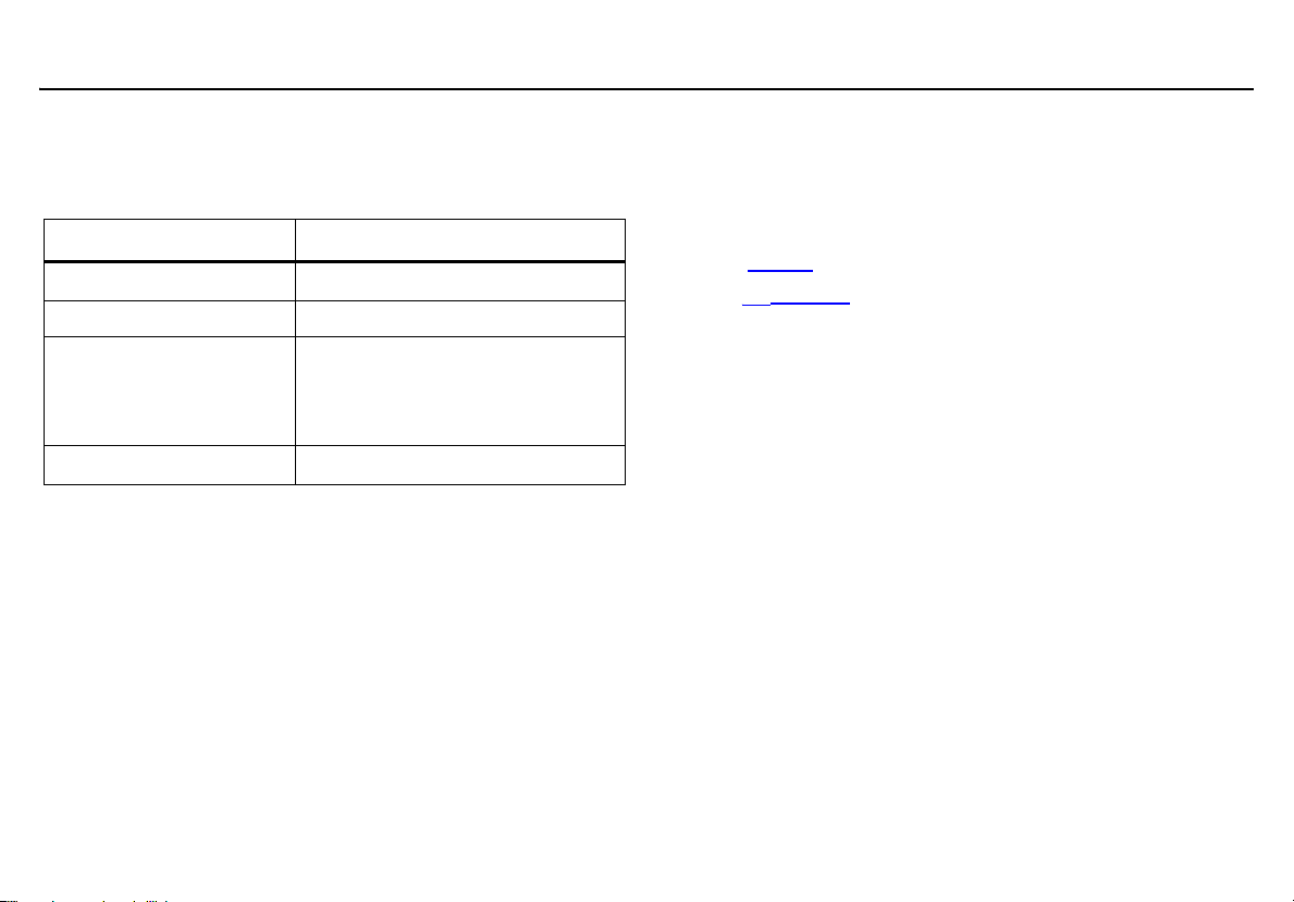
Gases Monitored
The following table lists the gases that are monitored by the detector.
Table 1. Gases Monitored
Gas Detected Unit of Measure
Hydrogen sulfide (H2S)
Carbon monoxide (CO) parts per million (ppm)
Combustible gases (LEL)
Oxygen (O
CAUTION: FOR SAFETY REASONS, THIS EQUIPMENT MUST BE
OPERATED AND SERVICED BY QUALIFIED PERSONNEL ONLY.
READ AND UNDERSTAND THIS USER MANUAL COMPLETELY
BEFORE OPERATING AND SERVICING.
)
2
parts per million (ppm)
a) percent of lower explosive limit
(%LEL)
b) percent by volume methane
0-5.0% v/v
% volume
Safety Information - Read First
Use the detector only as specified in this user manual and the quick reference guide, otherwise the protection provided by the detector may be
impaired.
International symbols used on the detector and in this user manual are
defined in Table 2.
Read the a Cautions on the following pages before using the detector.
ec Warning
This instrument contains a lithium polymer battery.
Dispose of lithium cells immediately. Do not
disassemble and do not dispose of in fire. Do not mix
with the solid waste stream. Spent batteries must be
disposed of by a qualified recycler or hazardous
materials handler.
2

a Cautions
• Warning: Substitution of components may impair Intrinsic Safety.
GasAlertQuattro
Safety Information - Read First
• Before using the detector, refer to Sensor Poisons and Contaminants
• Caution: For safety reasons, this equipment must be operated and serviced by qualified personnel only. Read and
understand this user manual completely before operating or servicing.
• Do not use the detector if it is damaged. Inspect the detector before using. Look for cracks and/or missing parts.
• If the detector is damaged or parts are missing, contact BW Technologies by Honeywell
• Only use sensor(s) that are specifically designed for the GasAlertQuattro. Refer to Replacement Parts and
Accessories.
• Calibrate the detector before first-time use and then on a regular schedule, depending on use and sensor exposure to
poisons and contaminants. BW Technologies by Honeywell recommends that the sensors be calibrated regularly and
at least once every 180 days (6 months).
• BW recommends to bump test the sensors before each day’s use to confirm their ability to respond to gas by
exposing the detector to a gas concentration that exceeds the alarm setpoints. Manually verify that the audible and
visual alarms activate. Calibrate if the readings are not within the specified limits.
• Protect the combustible sensor from exposure to lead compounds, silicones, and chlorinated hydrocarbons.
Although certain organic vapors (such as leaded gasoline and halogenated hydrocarbons) may temporarily inhibit
sensor performance, in most cases the sensor will recover after calibration.
• BW recommends the combustible sensor be checked with a known concentration of calibration gas after any known
exposure to catalyst contaminants/poisons (sulfur compounds, silicone vapors, halogenated compounds, etc).
• The combustible sensor is factory calibrated to 50% LEL methane. If monitoring a different combustible gas in the
% LEL range, calibrate the sensor using the appropriate gas.
• Warning: High off-scale LEL readings may indicate an explosive concentration.
.
immediately.
3

GasAlertQuattro
User Manual
• Only the combustible gas detection portion of this instrument has been assessed for performance by CSA
International.
• For use only in potentially explosive atmospheres where oxygen concentrations do not exceed 20.9% (v/v).
• Any rapid upscaling reading followed by a declining or erratic reading may indicate a gas concentration beyond upper
scale limit, which may be hazardous.
• Calibrate only in a safe area that is free of hazardous gas in an atmosphere of 20.9% oxygen.
a Cautions
• Use only BW approved batteries for the GasAlertQuattro detector. Refer to Specifications
• Charge the detector before first-time use. BW recommends the detector be charged after every workday.
• Charge the GasAlertQuattro using BW charger adapters designed for the GasAlertQuattro only. Do not use any other
charging adapter. Failure to adhere to this caution can lead to fire and/or explosion.
• Extended exposure of the GasAlertQuattro to certain concentrations of combustible gases and air may stress a
detector element, which can seriously affect its performance. If an alarm occurs due to high concentrations of
combustible gases, recalibration should be performed, or if needed, the sensor replaced.
• Do not test the combustible sensor’s response with a butane cigarette lighter; doing so will damage the sensor.
• Do not expose the detector to electrical shock or severe continuous mechanical shock.
• Deactivating the detector by removing the battery pack may cause improper operation and harm the detector.
• Do not immerse the detector in liquids.
• Do not attempt to disassemble, adjust, or service the detector unless instructions for that procedure are provided in
this user manual and/or that part is listed as a replacement part. Use only BW Technologies by Honeywell
Replacement Parts and Accessories
.
.
4

GasAlertQuattro
Safety Information - Read First
a Cautions
• Warning: The lithium battery (QT-BAT-R01) may present a risk of fire or chemical burn hazard if misused. Do not
disassemble, heat above 212°F (100°C), or incinerate.
• Warning: Do not use any other lithium batteries with the GasAlertQuattro detector. Use of any other cell can cause fire
and/or explosion. To order and replace the QT-BAT-R01 battery, refer to Replacement Parts and Accessories.
• Warning: Lithium polymer cells exposed to heat at 266°F (130°C) for 10 minutes can cause fire and/or explosion.
• Dispose of used lithium cells immediately. Do not disassemble and do not dispose of in fire. Do not mix with the solid
waste stream. Spent batteries must be disposed of by a qualified recycler or hazardous materials handler.
• Keep lithium cells away from children.
• Calibration cylinders that are used with a demand flow regulator must meet the following maximum inlet pressure
specifications:
• Disposable cylinders 0-1000 psig/70 bar
• Refillable cylinders 0-3000 psig/270 bar
• If using the detector near its upper or lower operating temperature, BW recommends zeroing or activating the detector
in that environment.
5

a Mises en garde
• Avertissement : Le remplacement d'un composant de l'appareil peut altérer sa sécurité intrinsèque.
• Avant toute utilisation du détecteur, reportez-vous à la section Sensor Poisons and Contaminants.
• Avertissement : Pour des raisons de sécurité, ce matériel doit être utilisé et entretenu exclusivement par du
personnel qualifié. Lisez attentivement le présent guide technique avant d’utiliser l’appareil ou d'en assurer
l'entretien, et assurez-vous d'en avoir bien compris les instructions.
• Ne pas utiliser le détecteur s'il est endommagé. Inspecter le détecteur avant de l'utiliser. Vérifier l'absence de fissures
et/ou s'assurer qu'aucune pièce ne manque.
• Si le détecteur est endommagée ou si des pièces sont manquantes, prenez contact avec BW Technologies by
Honeywell immédiatement.
• Utilisez uniquement des capteurs qui sont spécialement conçus pour le détecteur GasAlertQuattro. Reportez-vous à
la section Replacement Parts and Accessories.
• Étalonnez le détecteur avant sa première utilisation, puis de manière régulière, en fonction de l'utilisation et de
l'exposition du capteur aux poisons et autres contaminants. BW Technologies by Honeywell recommande
d'étalonner les capteurs régulièrement et au moins une fois tous les 180 jours (6 mois).
• Avant chaque utilisation quotidienne, BW recommande d'effectuer un test fonctionnel des capteurs afin de vérifier
qu'ils réagissent bien aux gaz présents, en exposant le détecteur à une concentration de gaz supérieure aux seuils
d'alarme. Vérifiez manuellement que les alarmes sonore et visuelle sont activées. Étalonnez l'appareil si les mesures
sont en dehors des limites spécifiées.
• Protégez le capteur de gaz combustibles contre toute exposition aux composés de plomb, aux silicones et aux
hydrocarbures chlorés. Bien que certaines vapeurs organiques (telles que l'essence au plomb ou les hydrocarbures
halogénés) puissent neutraliser provisoirement les performances du capteur, dans la plupart des cas, le capteur
retrouvera son fonctionnement normal après étalonnage.
• BW recommande de contrôler le capteur de gaz combustibles à l’aide d’une concentration de gaz d’étalonnage
connue après toute exposition à des poisons/contaminants catalytiques (composés de soufre, vapeurs de silicium,
produits halogénés, etc.).
• Le capteur de gaz combustibles est étalonné en usine au méthane, à une concentration de 50 % de la LIE. Si la
surveillance porte sur un autre gaz combustible dans la plage % LIE, étalonnez le capteur en utilisant le gaz
approprié.
6

GasAlertQuattro
Safety Information - Read First
• Avertissement : Des valeurs LIE hors échelle élevées peuvent indiquer la présence d'une concentration explosive.
• Seul l'élément de détection de gaz combustibles de cet appareil a fait l'objet d'une évaluation des performances
homologuée par CSA International.
• À utiliser exclusivement dans des atmosphères potentiellement explosives dans lesquelles la concentration
d'oxygène ne dépasse pas 20,9 % (v/v).
• Une lecture qui augmente rapidement, puis qui baisse, ou une lecture fantaisiste peuvent être représentatives d'une
concentration de gaz excédant la limite d’échelle supérieure et risquant donc d’être dangereuse.
• Veillez à effectuer l'étalonnage en zone sûre, exempte de gaz dangereux, dans une atmosphère contenant 20,9 %
d'oxygène.
• Utilisez uniquement des batteries approuvées par BW pour le détecteur GasAlertQuattro. Reportez-vous à la section
Specifications.
• Chargez le détecteur avant sa première utilisation. BW recommande de recharger le détecteur après chaque journée
d'utilisation.
• Chargez le détecteur GasAlertQuattro à l'aide d'adaptateurs pour chargeur de BW conçus uniquement pour le
détecteur GasAlertQuattro. N'utilisez aucun autre adaptateur de charge. Le non-respect de cette consigne peut
provoquer un incendie et/ou une explosion.
• L’exposition prolongée du détecteur GasAlertQuattro à certaines concentrations de gaz combustibles et d’air peut
fortement solliciter un élément du détecteur et nuire gravement à ses performances. En cas d’apparition d’une
alarme suite à de fortes concentrations de gaz combustibles, il faut effectuer un réétalonnage ou au besoin
remplacer le capteur.
• Ne testez pas la réactivité du capteur de gaz combustibles avec un briquet au butane ; vous endommageriez le
capteur.
7

GasAlertQuattro
User Manual
• N'exposez pas le détecteur à des chocs électriques ou à de forts chocs mécaniques répétés.
• Toute désactivation du détecteur par le retrait de la batterie risque de l'endommager et de provoquer un
fonctionnement inapproprié.
• N'immergez pas le détecteur dans des liquides.
• N'essayez pas de démonter, d'ajuster ou de réparer le détecteur, sauf si des instructions pour cette procédure sont
fournies dans le présent guide technique de référence et/ou si la pièce concernée est répertoriée comme pièce de
rechange. Utilisez uniquement ce que BW Technologies by Honeywell fournit en tant que Replacement Parts and
Accessories
• Avertissement : La batterie au lithium (QT-BAT-R01) peut présenter un risque d'incendie ou de brûlure chimique en
cas d'utilisation inappropriée. Veillez à ne jamais l'incinérer, la démonter ou l'exposer à une température supérieure
à 100 °C.
• Avertissement : Veillez à ne jamais utiliser d'autres batteries au lithium avec le détecteur GasAlertQuattro. Toute
autre batterie pourrait provoquer un incendie et/ou une explosion. Pour commander et réinstaller la batterie QT-BATR01, reportez-vous à la section Replacement Parts and Accessories.
• Avertissement : Les piles au lithium polymère exposées à une température supérieure à 130 °C (266 °F) pendant plus
de 10 minutes peuvent provoquer un incendie et/ou une explosion.
• Mettez immédiatement au rebut les piles au lithium usagées. Veillez à ne jamais les démonter ou les jeter au feu. Ne
les mélangez pas avec d'autres déchets solides. Les batteries usagées doivent être éliminées par un centre de
recyclage agréé ou un centre de traitement des matières dangereuses.
• Gardez les piles au lithium hors de portée des enfants.
• Toutes les bouteilles d'étalonnage utilisées avec des régulateurs de débit à la demande doivent répondre aux
spécifications de pression d'entrée maximale suivantes :
• Bouteilles jetables de 0 à 1 000 psig/70 bars
• Bouteilles rechargeables de 0 à 3 000 psig/270 bars
• Si vous utilisez le détecteur près de sa température de fonctionnement supérieure ou inférieure, BW recommande de
mettre le détecteur à zéro ou de l'activer dans cet environnement.
8
Safety Information - Read First
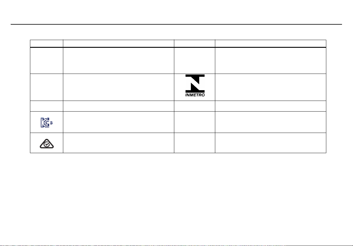
Table 2. International Symbols
Symbol Meaning Symbol Meaning
International Electrotechnical Commission
n
g
Approved to both U.S. and Canadian Standards by CSA International
European Explosives Protection
IECEx
Scheme for Certification to Standards for
Electrical Equipment for Explosive Atmo-
spheres
Natural Institute of Metrology, Quality, and
Technology. Conforms to Brazilian
INMETRO Certification.
GasAlertQuattro
X
Conforms to European Union Directives
Korean Testing Laboratory
Australian Regulatory Compliance Mark
ATEX
EAC EX
Conforms to European ATEX Directives
Customs Union Russian Certification
9

GasAlertQuattro
User Manual
Sensor Poisons and Contaminants
Several cleaners, solvents, and lubricants can contaminate and cause
permanent damage to sensors. Before using cleaners, solvents, and
lubricants in close proximity to the detector sensors, read the following
caution and refer to Table 3.
a Caution
Use only the following BW Technologies by Honeywell
recommended products and procedures:
• Use water-based cleaners.
• Use non-alcohol based cleaners.
• Clean the exterior of the detector with a soft,
damp cloth.
• Do not use soaps, polishes, or solvents.
The following table lists common products to avoid using around
sensors.
Table 3. Sensor Poisons and Contaminants
Cleaners and
Lubricants
Brake cleaners Silicone cleaners
Lubricants Silicone based
Rust inhibitors Hand/body and
Window and glass
cleaners
Dishsoaps Mold releasing
Citrus based cleaners Polishes
Alcohol based
cleaners
Hand sanitizers
Anionic detergents
Methanol
(fuels and antifreezes)
Silicones Aerosols
Bug repellents
and protectants
adhesives, sealants, and gels
medicinal creams
that contain silicone
Tissues containing
silicone
agents
and sprays
Lubricants
Rust inhibitors
Window and
glass cleaners
10

GasAlertQuattro
User Manual
Getting Started
The list below provides the standard items included with the detector.
If the detector is damaged or parts are missing, contact the place of
purchase immediately.
• Sensors: H
(depending upon sensors ordered with detector)
Detectors that are configured for 1, 2, or 3 gases may contain a
dummy sensor in one of the four sensor locations.
• Calibration cap
• Calibration hose (3 ft./1 m) w/ quick connect
• Charging adapter or 3 alkaline batteries (dependent on type of battery pack)
• Screwdriver
• Quick Reference Guide
• Supplementary booklet including a quick reference card
• Technical reference guide on CD-ROM
For a list of GasAlertQuattro accessories, refer to Replacement Parts
and Accessories.
Fleet Manager II Options
Fleet Manager II software can be downloaded without cost from BW
Technologies by Honeywell’s website www.gasmonitors.com
Fleet Manager II CD-ROM is shipped with the MicroDock II base station.
S, CO, O2, and combustible LEL
2
Note
.
The detector is shipped with the sensors and a rechargeable or alkaline
battery pack. To replace sensors and maintain the battery pack, refer
to the following:
•
Replacing the Sensors
• Charging the Rechargeable Battery
• Replacing the Battery Pack
• Replacing the Alkaline Batteries
To order parts, refer to Replacement Parts and Accessories.
To become oriented with the features and functions of the detector, refer
to the following figures and tables:
• Figure 1.
• Screen Elements
• Table 5.
and Table 4. describes the detector’s components.
describes the LCD icons and screen elements.
describes the detector’s pushbutton.
11
GasAlertQuattro
Parts of the GasAlertQuattro
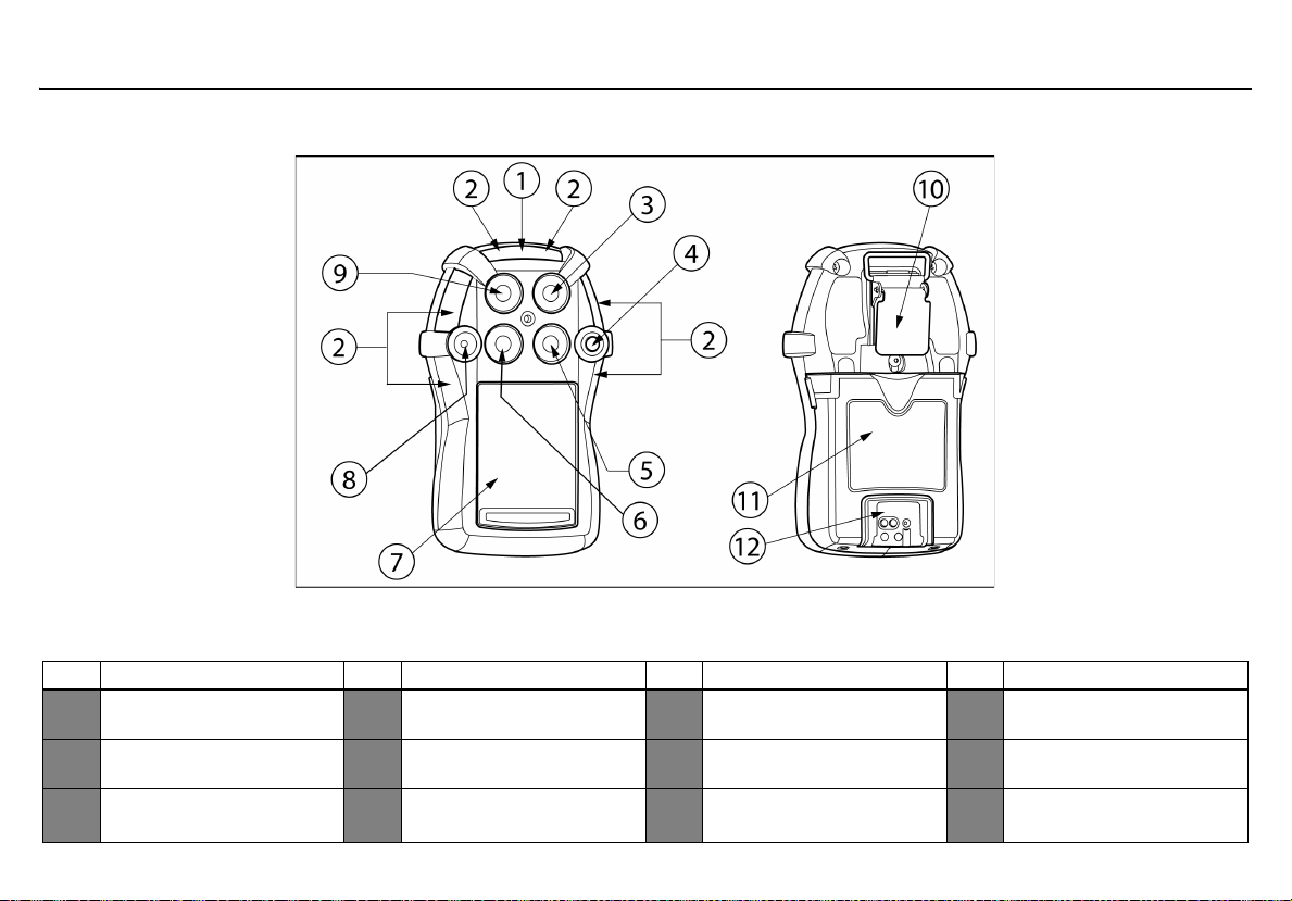
Parts of the GasAlertQuattro
Figure 1. Parts of the GasAlertQuattro
Table 4. Parts of the GasAlertQuattro
Item Description Item Description Item Description Item Description
1 IntelliFlash (green LED) 4 Button 7
Visual alarm indicator (red
2
LED)
Hydrogen sulfide (H
3
sensor
S)
2
5 Combustible (LEL) sensor 8Audio alarm 11 Batter y pack
Carbon monoxide (CO)
6
sensor
Liquid crystal display
(LCD)
Oxygen (O
9
10 Alligator clip
)
2
Charging connector and
12
IR interface
12
GasAlertQuattro
User Manual
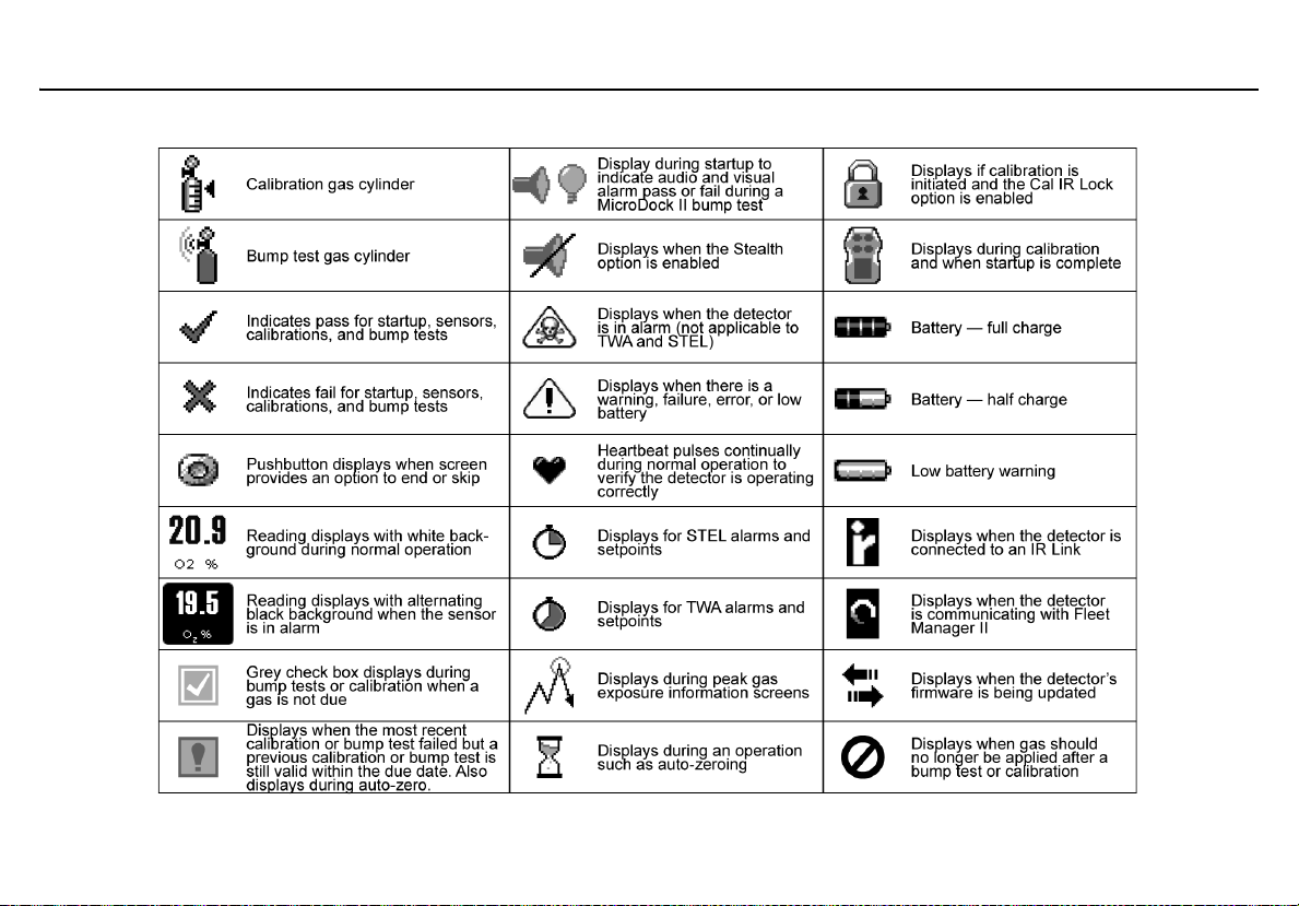
Screen Elements
13

GasAlertQuattro
User Manual
Button Description
C
Table 5. Button
• To activate the detector, press and hold C in a safe area that is free of hazardous gas and in an atmo-
sphere of 20.9% oxygen.
• To deactivate the detector, press and hold C during the powering off countdown. Release C when OFF
displays.
• To view the date/time, current battery power, calibration due date, bump test due date, TWA, STEL, and
peak readings, press C twice rapidly. To clear the TWA, STEL, and peak readings, press and hold C
when the LCD displays Hold C to reset peaks, TWA, STEL.
• To initiate calibration, press and hold C while the detector performs the OFF countdown. Continue holding
C while the LCD briefly deactivates and then reactivates to begin the calibration countdown. Release C
when Calibration started displays.
• To activate the backlight, press C and release.
• To acknowledge latching alarms, press C.
• To acknowledge a low alarm and temporarily disable the audible alarm, press C. The Low Alarm
Acknowledge option must be enabled in Fleet Manager II.
14
• To acknowledge any of the “due today” messages (calibration and bump test), press C. If the force calibration option is enabled, a calibration cannot be bypassed. If the force bump option is enabled, a bump test
cannot be enabled.
GasAlertQuattro
Activating/Deactivating the Detector
Activating/Deactivating the Detector
a Caution
Only activate the detector in a safe area that is free of
hazardous gas in an atmosphere of 20.9% oxygen.
Activate: Press and hold C.
Deactivate: Press and hold C during the powering off countdown.
Release C when OFF displays.
Startup Sequence
If an error screen displays during the startup sequence, refer to Startup
Troubleshooting.
When the detector is activated, it performs several tests during the
startup sequence. Confirm the following tests occur.
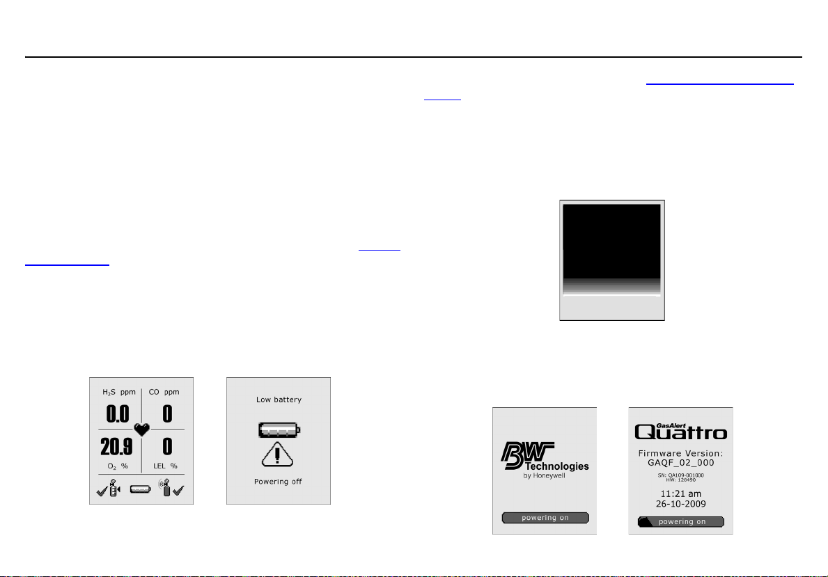
Battery Test
If battery power is critically low upon startup, the detector displays the
following screens and then deactivates.
Recharge the battery for 6 hours. Refer to Charging the Rechargeable
Battery.
Segment Test
1. The segment test verifies that the visual, audio, and
vibrate functions are operating correctly. The detector
alarms, vibrates, and displays the following screen.
Product Identification and Firmware Revision
2. The following two screens display showing the BW and product
identification, and the firmware revision.
15
GasAlertQuattro
User Manual
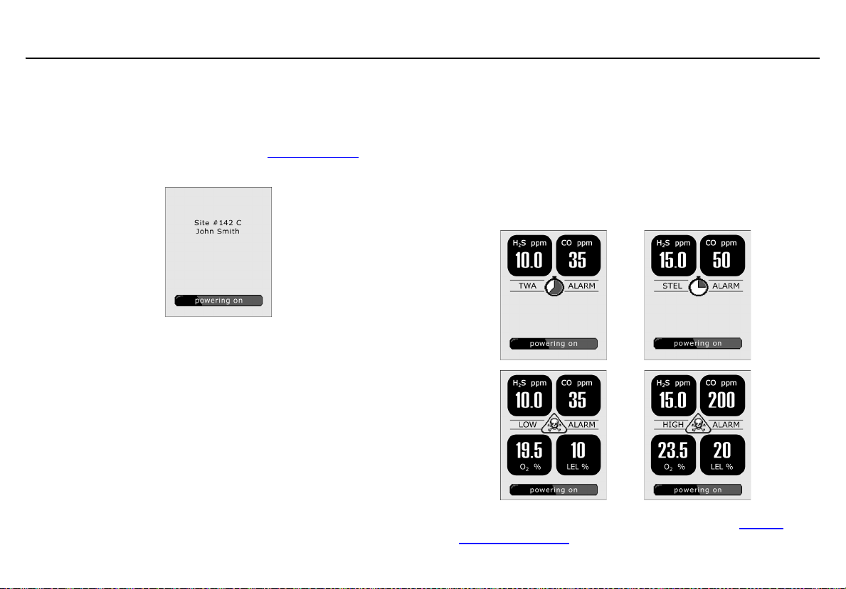
Startup Message
3. If data is entered in the Startup Message field in Fleet Manager
II, a startup message (50 characters maximum) displays on the
LCD. If a startup message has not been entered, it is bypassed
during the startup sequence. Refer to Startup Message
Options.
Note
To make a line break to force text to the next line, as in the
example above, press the
| (pipe or vertical bar) key.
in User
Alarm Setpoints
4. The alarm setpoints defined in Fleet Manager II display on the
detector in the following order:
• TWA (time-weighted average) CO and H
• STEL (short-term exposure limit) CO and H
• Low
•High
S only
2
2
S only
16
Note: Alarm setpoints may vary by region. Refer to Sample
Gas Alarm Setpoints.
GasAlertQuattro
Startup Sequence
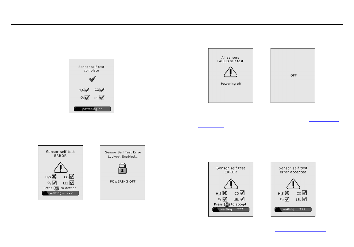
Sensor Self Test
The detector tests the sensors during startup. If all sensors pass, the
following screen displays.
Lockout Enabled
If Lockout on Self-test Error is enabled and a sensor fails the
startup sensor self-test, the following screens display.
OFF then displays and the detector deactivates. For all sensor and selftest error screens, refer to Startup Troubleshooting
.
If all sensors fail the startup sensor self-test, the following
screens display.
The detector then automatically deactivates.
For all sensor and self-test error screens, refer to Startup Trou-
bleshooting.
Lockout Disabled
If Lockout on Self Test Error is disabled and a sensor fails
the self-test, the following screens display.
BW Technologies by Honeywell recommends that the sensor
be replaced immediately. Refer to Replacing the Sensors
.
17
GasAlertQuattro
User Manual
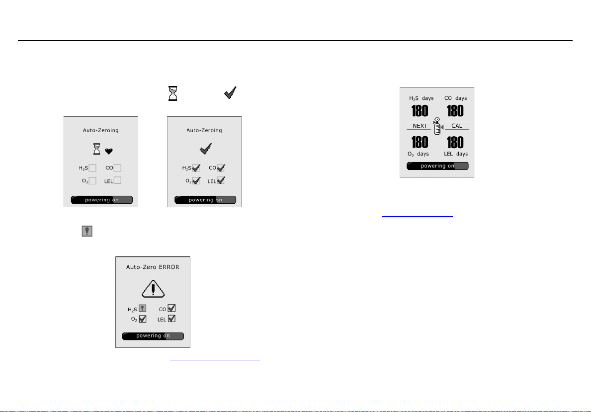
Auto Zero Sensors
5. The detector zeros the sensors.
When auto-zeroing is complete, changes to .
If a sensor fails the auto-zero test, the Auto-zero error screen
displays. indicates which sensor failed and that a previous
auto-zero result for that sensor will be used to zero the sensor.
Next Calibration Due
6. The next calibration due date for each sensor displays.
Note
N/A displays when the calibration interval has been defined as
0 days. Refer to Calibration Interval
a Warning
BW Technologies by Honeywell recommends that the
sensors be calibrated regularly and at least once every
180 days (6 months).
.
For sensor error causes, refer to Startup Troubleshooting
18
.
 Loading...