

BW Technologies GasAlertMicro 5, GasAlertMicro 5 PID, GasAlertMicro 5 IR Instruction Manual
1, 2, 3, 4, and 5-Gas Detector
User Manual

Limited Warranty and Limitation Liability
BW Technologies LP (BW) warrants the product to be free from defects in material and workmanship under normal use and service for a period of two years, beginning on the date of
shipment to the buyer. Thi s warranty extends only to t he sale of new and u nused product s to t he original buyer. BW’s warranty obligation is limited, at BW’s option, to refu nd of the pur chase
price, repair or replacement of a defective product that is returned to a BW authorized service center within the warranty period. In no event shall BW’s liability hereunder exceed the
purchase price actually paid by the buyer for the Product.
This warranty does not include:
a) fuses, disposable batteries or the routine replacement of parts due to the normal wear and tear of the product arising from use;
b) any product which in BW’s opinion, has been misused, altered, neglected or damaged, by accident or abnormal conditions of operation, handling or use;
c) any damage or defects attributable to repair of the product by any person other than an authorized dealer, or the installation of unapproved parts on the product; or
The obligations set forth in this warranty are conditional on:
a) proper storage, installation, calibration, use, ma intenance and compliance with the product manual instructions and any other applicable recommendations of BW;
b) the buyer promptly notifying BW of any defect and, if required, promptly making the product available for correction. No goods shall be returned to BW until receipt by the buyer of
shipping instructions from BW; and
c) the right of BW to require that the buyer provide proof of purchase such as the original invoice, bill of sale or packing slip to establish that the product is within the warranty period.
THE BUYER AGREES THAT THIS WARRANTY IS THE BUYER’S SOLE AND EXCLUSIVE REMEDY AND IS IN LIEU OF ALL OTHER WARRANTIES, EXPRESS OR IMPLIED, INCLUDING BUT NOT LIMITED TO ANY
IMPLIED WARRANTY OF MERCHANTABILITY OR FITNESS FOR A PARTICULAR PURPOSE. BW SHALL NOT BE LIABLE FOR ANY SPECIAL, INDIRECT, INCIDENTAL, OR BASED ON CONTRACT, TORT OR RELIANCE
OR ANY OTHER THEORY.
Since some countries or states do not allow limitation of the term of an implied warranty, or exclusion or limitation of incidental or consequential damages, the limitations and exclusions of
this warranty may not apply to every buyer. If any provision of this warr anty is held invalid or unenforceable by a court of competent jurisdiction, such holding will not affect the validity or
enforceability of any other provision.
BW Technologies by Honeywell BW Technologies by Honeywell BW Technologies by Honeywell
Corporate Headquarters America Europe
2840 - 2nd Ave. SE 3279 West Pioneer Parkway 5 Canada Close
Calgary, AB Arlington, TX Banbury, Oxfordshire
Canada T2A 7X9 USA 76013 United Kingdom OX16 2RT

Table of Contents
Title Page
Limited Warranty and Limitation Liability ........................................................................................................................ 0
Contacting BW Technologies by Honeywell.................................................................................................................... 1
Introduction......................................................................................................................................................................... 1
Gases Monitored ..................................................... .... ... ... ... ... .... ... ................................................................................. 2
Safety Information - Read First.......................................................................................................................................... 2
aCautions .......................................................................................................................................................................... 3
Sensor Poisons and Contaminants .................................................................................................................................. 6
Getting Started.................................................................................................................................................................... 8
Parts of the GasAlertMicro 5/PID/IR.................................................................................................................................. 9
Screen Elements................................................... ... ....................................... ... ... ............................................................ 10
Pushbuttons...................................................................................................................................................................... 11
Activating the Detector..................................................................................................................................................... 12
Self-Tests....................................................................................................................................................................... 12
Battery Test .............................................................................................................................................................. 12
Datalogging (Optional).............................................................................................................................................. 13
Pump Test ................................................................................................................................................................ 15
Due-Lock Enabled.................................................................................................................................................... 16
Force Calibration Enabled........................................................................................................................................ 17
Bump Daily Enabled................................................................................................................................................. 17
Self-Test Pass ................................................... ... ....................................... ... ... ............................................................ 19
Self Test Fail.................................................................................................................................................................. 19
Battery Test ................................................................................................................................................................... 19
Datalogger Operation (Optional).................................................................................................................................... 19
i

GasAlertMicro 5/PID/IR
User Manual
Title Page
Deactivating the Detector.................................................................................................................................................20
User Options Menu ........................................................................................................................................................... 20
Exit User Options Menu................................................................................................................................................. 21
Options Menu.... .... ... ... ....................................... ... ... ....................................... ... .... ........................................................21
Backlight ................................................................................................................................................................... 22
Confidence Beep ......................................................................................................................................................22
Due-Lock .................................................................................................................................................................. 22
Latched Alarms.........................................................................................................................................................22
Passcode Protect...................................................................................................................................................... 23
Safe Display..............................................................................................................................................................23
Sensor Configuration .....................................................................................................................................................24
Sensor Enable/Disable .............................................................................................................................................25
Span Gas Value........ ....................................... ... .... ...................................... .... ... .....................................................26
STEL Period .............................................................................................................................................................26
TWA Method.............................................................................................................................................................27
Resolution................................................................................................................................................................. 27
%Vol CO
%Vol CH
(CO2 Sensors Only)..................................... ....................................... ... ... ............................................... 28
2
(LEL Sensors Only)..................................................................................................................................28
4
Correction Factor (CF)..............................................................................................................................................28
Automatic Oxygen (O
) Calibration..................................... ....................................... ... .... ........................................30
2
Logger Option ................................................................................................................................................................ 30
Clock Option ..................................................................................................................................................................31
Language Selection ........... ... ....................................... ... ... ....................................... ... ... ...............................................32
Tech Mode..................................................................................................................................................................... 32
Sensors.....................................................................................................................................................................33
Initialize..................................................................................................................................................................... 34
Force Calibration ......................................................................................................................................................35
ii

GasAlertMicro 5/PID/IR
User Manual
Title Page
Bump Daily ................................................... ... ... .... ...................................... .... ... .....................................................35
Stealth Mode............................................................................................................................................................. 36
Sleep Mode......... ... ....................................... ... ... ....................................... ... .... ........................................................36
Alarms................................................................................................................................................................................37
Gas Exposures Computed.............................................................................................................................................40
Viewing Gas Exposures.................................................................................................................................................40
Clearing Gas Exposures................................................................................................................................................41
Gas Alarm Setpoints...................................................................................................................................................... 41
Viewing the Alarm Setpoints..........................................................................................................................................41
Resetting Gas Alarm Setpoints......................................................................................................................................42
Stopping a Gas Alarm....................................................................................................................................................43
Sensor Alarm ................................................................................................................................................................. 43
Pump Alarm ............. ....................................... ... ... ....................................... ... ... ............................................................43
Low Battery Alarm.......................................................................................................................................................... 44
Automatic Deactivation Alarm........................................................................................................................................ 44
Calibration and Setting Alarm Setpoints ........................................................................................................................ 44
Guidelines......................................................................................................................................................................44
Diagnostics Testing.................................. ... ....................................... ... .... ... ..................................................................45
Applying Gas to the Sensors ................................................... .... ... ... ... .... ... ... ...............................................................46
Single Gas Calibration Cap ......................................................................................................................................46
Calibration Procedure ........... ... ... ... ....................................... ... .... ...................................... ............................................ 47
Start Calibration........................................................................................................................................................ 48
Auto Zero and Oxygen (O
Zero CO
(GasAlertMicro 5 IR only) .........................................................................................................................48
2
) Sensor Calibration ..... ... ....................................... ... ... ....................................... ... ... .....48
2
Passcode Protect Activated......................................................................................................................................49
Auto Span................................................................................................................................................................. 50
Successful Span.......................................................................................................................................................52
iii

GasAlertMicro 5/PID/IR
User Manual
Title Page
Setting the Calibration Due Date ..............................................................................................................................52
Alarm Setpoints ............................................ ... ... .... ... ....................................... ... ... ..................................................54
Setting the Remaining Alarm Setpoints....................................................................................................................56
Finish Calibration......................................................................................................................................................56
Verification................................................................................................................................................................56
Unsuccessful Span................................................................................................................................................... 57
Attaching the Accessories...............................................................................................................................................59
Installing the Pump Module............................................................................................................................................59
Replacing the Pump Filter..............................................................................................................................................60
Replacing the Pump Nozzle...........................................................................................................................................61
Attaching the Auxiliary Filter ..........................................................................................................................................61
Attaching the Sample Probe ..........................................................................................................................................63
Datalogger .........................................................................................................................................................................64
MMC/SD Card Compatibility............................................................................................................................................. 64
Inserting the MMC/SD Card...........................................................................................................................................64
MMC/SD Card Troubleshooting.......................................................................................................................................65
Restoring Datalog Files..................................................................................................................................................66
Reformatting the MMC/SD Card....................................................................................................................................67
Import Datalogs to Fleet Manager II .......................................... .... ... ....................................... ... ..................................... 68
Minimum PC Requirements...........................................................................................................................................68
Importing from MicroDock II to Fleet Manager II............................................................................................................68
Import to Fleet Manager II Using a Card Reader...........................................................................................................68
View Datalog Files in Spreadsheets................................................................................................................................ 69
Example of a Datalog Spreadsheet..........................................................................................................................70
Maintenance ...................................................................................................................................................................... 73
Battery Cautions ............................................... ... ... .... ...................................... .... ... ..................................................... 73
Charging the Battery...................................................................................................................................................... 73
iv

GasAlertMicro 5/PID/IR
User Manual
Title Page
Replacing the Alkaline Batteries ....................................................................................................................................74
Replacing the Lithium Battery Pack...............................................................................................................................75
Replacing a Sensor or Sensor Filter..............................................................................................................................75
Photoionization Detector (PID) ............................................. ... .... ... ... ... .... .....................................................................77
Clean or Replace the Lamp.................................... ... ... ... ... .... ... ... ....................................... ... ..................................77
Replace the Lamp.. ....................................... ... ... ....................................... ... .... ........................................................78
Replace the Electrode Stack ........................................ ... ... .... ...................................... .... ... .....................................78
Troubleshooting................................................................................................................................................................ 79
Replacement Parts and Accessories .............................................................................................................................. 85
Specifications.................................................................................................................................................................... 87
General Specifications for Datalogger Units.................................................................................................................. 90
GasAlertMicro 5/PID/IR Downloadable Datalogger .......................................................................................................90
PID Correction Factor (CF) Library..................................................................................................................................91
v

GasAlertMicro 5/PID/IR
User Manual
Title Page
vi

List of Figures
Figure Title Page
1. Parts of the GasAlertMicro 5/PID/IR...................................................................................................................... 9
2. Screen Elements................................................................................................................................................. 10
3. Applying Gas to the Sensors............................................................................................................................... 46
4. Single Gas Calibration Cap................................................................................................................................. 47
5. Removing the Single Gas Calibration Cap.......................................................................................................... 47
6. Installing the Pump Module................................................................................................................................. 59
7. Replacing the Pump Filter................................................................................................................................... 60
8. Replacing the Pump Nozzle................................................................................................................................ 61
9. Attaching the Auxiliary Filter............................................................................................................................... 61
10. Attaching the Filter Cord..................................................................................................................................... 62
11. Attaching the Sample Probe................................................................................................................................ 63
12. Inserting/Removing the MMC/SD Card............................................................................................................... 65
13. Replacing the Alkaline Batteries.......................................................................................................................... 74
14. Replacing the Lithium Battery Pack ............................................... ... ... ............................................................... 75
15. Replacing a Sensor or Sensor Filter ................................................................................................................... 76
16. Parts of the PID................................................................................................................................................... 77
vii

GasAlertMicro 5/PID/IR
User Manual
viii

List of Tables
Table Title Page
1. Gases Monitored........................................... .... ...................................... .... ... ....................................................... 2
2. Sensor Poisons and Contaminants....................................................................................................................... 6
3. International Symbols.............. ... ... ... .... ... .............................................................................................................. 7
4. Parts of the GasAlertMicro 5/PID/IR...................................................................................................................... 9
5. Screen Elements................................................................................................................................................. 10
6. Pushbutton .......................................................................................................................................................... 11
7. Alarms ................................................................................................................................................................. 37
8. Computed Gas Exposures ............ ....... ... ... ... ...................................................................................................... 40
9. Gas Alarm Setpoints ..................................................... .... ... ... ... ....................................... .................................. 41
10. OSHA Sample Factory Alarm Setpoints.............................................................................................................. 42
11. Applying Gas to the Sensors............................................................................................................................... 46
12. Single Gas Calibration Cap................................................................................................................................. 47
13. Time Required to Span ....................................................................................................................................... 51
14. Installing the Pump Module................................................................................................................................. 59
15. Datalog Spreadsheet Example............................................................................................................................ 70
16. Datalog Status Codes ......................................................................................................................................... 71
17. Datalog Gas and Correction Factor Sensor Codes............................................................................................. 72
18. Replacing the Alkaline Batteries.......................................................................................................................... 74
19. Replacing a Sensor or Sensor Filter .................................................................................................................. 76
20. Parts of the PID sensor ....................................................................................................................................... 77
21. Troubleshooting................................................................................................................................................... 79
22. Replacement Parts and Accessories .................................................................................................................. 85
23. PID Corrections Factor (CF) Library.................................................................................................................... 91
ix

GasAlertMicro 5/PID/IR
User Manual
x

GasAlertMicro 5/PID/IR
Contacting BW Technologies by Honeywell
To con tact BW Technologies by Honeywell, call
USA: 1-888-749-8878
Canada: 1-800-663-4164
Europe: +44 (0) 1295 700300
Other countries: +1-403-248-9226
Address correspondence to
BW Technologies by Honeywell
2840 – 2 Avenue S.E.
Calgary, AB T2A 7X9
CANADA
Email: info@gasmonitors.com
Website: www.gasmonitors.com
ISO 9001
Introduction
a Warning
To ensure personal safety, read the Safety Information -
Read First and Cautions before using the detector.
The GasAlertMicro 5, GasAlertMicro 5 PID, and GasAlertMicro 5 IR
gas detectors (“the detector”) warn of hazardous gas at levels above
user-defined alarm setpoints.
The detector is a personal safety device. It is your responsibility to
respond properly to the alarm.
Note
Unless reference is made to a specific detecto r model, the
GasAlertMicro 5, GasAlertMicro 5 PID, and GasAlertMicro 5 IR
detectors are referred to as GasAlertMicro 5/PID/IR.
Refer to Gases Monitored
prior to operating the detector.
1

GasAlertMicro 5/PID/IR
User Manual
Gases Monitored
The following table lists the gases that are monitored by the detector.
Table 1. Gases Monitored
Gas Detected Unit of Measure
Oxygen (O2)
Combustible gases (LEL)
Carbon monoxide (CO) parts per million (ppm)
Hydrogen sulfide (H
Phosphine (PH
Sulfur oxide (SO
Chlorine (Cl
)
2
Ammonia (NH
Nitrogen dioxide (NO
S)
2
)
3
)
2
)
3
)
2
Hydrogen cyanide (HCN) parts per million (ppm)
Chlorine dioxide (ClO
Ozone (O
)
3
)
2
Volatile orga nic compounds
(VOC)
Carbon dioxide (CO
) parts per million or %vol CO
2
% volume
a) percent of lower explosive
limit (%LEL)
b) percent by volume
methane 0-5.0% v/v
parts per million (ppm)
parts per million (ppm)
parts per million (ppm)
parts per million (ppm)
parts per million (ppm)
parts per million (ppm)
parts per million (ppm)
parts per million (ppm)
parts per million (ppm)
CAUTION: FOR SAFETY REASONS, THIS EQUIPMENT MUST BE
OPERATED AND SERVICED BY QUALIFIED PERSONNEL ONLY.
READ AND UNDERSTAND THIS USER MANUAL COMPLETELY
BEFORE OPERATING AND SERVICING.
Safety Information - Read First
Use the detector only as specified in this user manual, otherwise the
protection provided by the detector may be impaired.
International symbols used on the detector and in this user manual are
defined in Table 3.
.
Read the Cautions on the following pages before using the dete ctor.
ec Warning
This instrument contains batteries. Do not mix with the
solid waste stream. Spent batteries must be disposed of
by a qualified recycler or hazardous materials handler.
Dispose of lithium cells immediately. Do not
disassemble and do not dispose of in fire. Do not mix
with the solid waste stream. Spent batteries must be
disposed of by a qualified recycler or hazar dous
materials handler.
2
2

GasAlertMicro 5/PID/IR
a
Cautions
aCautions
• Warning: Substitution of components may impair Intrinsic Safety.
• Caution: For safety reasons, this equipment must be operated and serviced by qualified person nel only. Read and understand
this user manual completely before operating or servicing.
• Do not use the detector if it is damaged. Inspect the detector before using. Look for cracks and/or missing parts.
• If the detector is damaged or parts are missing, contact BW Technologies by Honeywell
• Use only sensor(s) that are specifically designed for the GasAlertMicro 5/PID/IR detectors. Refer to Replacement Parts and
Accessories.
• Calibrate the detector before first-time use and then on a regular schedule, depending on use and sensor exposure to poisons
and contaminants. Sensors must be calibrated regularly and at least once every 180 days (6 months).
• BW recommends to bump test the sensors, before each day’s use, to confirm their ability to respond to gas by exposing the
detector to a gas concentration that exceeds the alarm setpoints. Manually verify that the audible and visual alarms are ac tivated.
Calibrate if the readings are not within the specified limits.
• BW recommends the combustible sensor be checked with a known concentration of calibration gas af ter any known exposure to
catalyst contaminants/poisons (sulfur compounds, silicon vapors, halogenated compounds, etc).
• The combustible sensor is factory calibrated to 50 % LEL methane. If monitoring a different combustible gas in the % LEL range,
calibrate the sensor using the appropriate gas.
• Warning: High off-scale LEL readings may indicate an explosive concentration.
• Only the combustible gas detection portion of this instrument has been assessed for performance by CSA International.
• Protect the combustible sensor from exposure to lead compounds, silicones, and chlorinated hydrocarbons. Although certain
organic vapors (such as leaded gasoli ne and halogenated hydrocarbons) may temporari ly inhibit sensor performance, in most
cases, the sensor will recover after calibration.
• Before using common products around sensors, refer to Sensor Poisons and Contaminants
immediately.
.
3

GasAlertMicro 5/PID/IR
User Manual
aCautions
• Any rapid up-scaling reading followed by a declining or erratic reading may indicate a gas concentration beyond upper scale
limit, which may be hazardous.
• Calibrate only in a safe area that is free of hazardous gas, in an atmosphere of 20.9% oxygen.
• Use only BW approved batteries for the GasAlertMicro 5/PID/IR detectors. Refer to Replacement Parts and Accessories
• Charge the detector before first-time use. BW recommends the detector be charged after every workday.
• Charge the battery pack immediately when a low battery alarm occ urs.
• Read and adhere to the battery cautions provided in Battery Cautions
• Charge the GasAlertMicro 5/PID/IR batteries using the recommended charging adapter only. Do not use any other charging
adapter. Failure to adhere to this caution can lead to fire and/or explosion.
• Read and adhere to all instructions in the charger user manual. Failure to do so can result in fire, electrical shock, personal
injury, and/or property damage.
• Extended exposure of the GasAlertMicro 5/PID/IR detectors to certain concentrations of combustible gases and air may stress a
detector element, which can seriously affect its performance. If an alarm occurs due to high concentration of combus tible gases ,
recalibration should be performed, or if needed, the sensor replaced.
• Protect the PID sensor from exposure to silicone vapors.
• When calibrating O
to ensure accurate calibration. For more information, refer to Single Gas Calibration Cap
• Replace the CO
• The optional pump (M5-PUMP) is certified for use with the GasAlertMicro 5/PID/IR detectors only.
• Do not immerse the detector in liquids.
and ClO2 sensors that are located in the Toxic 2 sensor position, a single gas calibration cap must be used
3
sensor only in a safe area that is free of hazardous gas.
2
.
.
4
.

GasAlertMicro 5/PID/IR
a
aCautions
• Do not test the combustible sensor’s response with a butane cigarette lighter; doing so will damage the sensor.
• Do not expose the detector to electrical shock or severe continuous mechanical shock.
• Do not attempt to disassemble, adjust, or service the detector unless instructions for that procedure are provided in the user
manual and/or that part is listed as a replacement part. Use only BW Technologies by Honeywell Replacement Parts and
Accessories.
• The detector warranty is void if customer, personnel, or third parties damage the detector during repair attempts. Repair
attempts made by non-BW Technologies by Honeywell repair/service personnel voids this warranty.
Lithium Battery Packs
• Warning: The lithium battery (M5-BAT08) may present a risk of fire or chemical burn hazard if misused. Do not disassemble,
heat above 212°F (100°C), or incinerate.
• Do not use any other lithium batteries with the GasAlertMicro 5/PID/IR detectors. Use of any other cell can cause fire and/or
explosion. To order and replace the M5-BAT08 battery, refer to Replacement Parts and Accessories.
• Warning: Lithium polymer cells exposed to heat at 266°F (130°C) for 10 minutes can cause fire and/or explosion.
• Dispose of used lithium cells immediately. Do not disassemble and do not dispose of in fire. Do not mix with the solid waste
stream. Spent batteries must be disposed of by a qualified recycler or hazardous materials handler.
• Keep lithium cells away from children.
Cautions
5

GasAlertMicro 5/PID/IR
User Manual
Sensor Poisons and Contaminants
Several cleaners, solvents, and lubricants can contaminate and cause
permanent damage to sensors. Before using cleaners, solvents, and
lubricants in close proximity to the detector sensors, read and adhere
to the following caution and table.
a Caution
Use only the following BW Technologies by Honeywell
recommended products and pr ocedures:
• Use water based cleaners.
• Use non-alcohol based cleaners.
• Clean the exterior with a soft, damp cloth.
• Do not use soaps, polishes, or solvents.
The following table lists common products to avoid using around
sensors.
Table 2. Sensor Poisons and Contaminants
Cleaners and
Lubricants
Brake cleaners Silicone cleaners
Lubricants Silicone based
Rust inhibitors Hand/body and
Window and glass
cleaners
Dishsoaps Mold releasing
Citrus based cleaners Polishes
Alcohol based
cleaners
Hand sanitizers
Anionic detergents
Methanol
(fuels and antifreezes)
Silicones Aerosols
Bug repellents
and protectants
adhesives, sealants, and gels
medicinal creams
that contain silicone
Tissues containing
silicone
agents
and sprays
Lubricants
Rust inhibitors
Window and
glass cleaners
6

Table 3. International Symbols
Symbol Description
GasAlertMicro 5/PID/IR
Sensor Poisons and Contaminants
n
g
X
ATEX
IECEx
Approved to both U.S. and Canadian Standards by CSA International
European Explosives Protection
Conforms to European Union Directives
Conforms to European ATEX Directives
International Electrotechnical Commission Scheme for Certification to Standards for Electrical Equipment for
Explosive Atmospheres
7

GasAlertMicro 5/PID/IR
User Manual
Getting Started
The list below provides the standard ite ms included with the detector.
If the detector is damaged or parts are missing, contact the place of
purchase immediately.
• Batteries: Three replaceable alkaline cells with battery pack, or
one rechargeable lithium battery pack
• Sensors: O
PID, or CO
• Calibration cap and hose
• Single gas calibration cap
• Screwdriver
• Quick reference guide
• Quick reference card
• User manual and training on CD-ROM
• Fleet Manager II (if applicable)
To order parts, refer to Replacement Parts and Accessories
, combustible (LEL), toxic, H2S/CO (TwinTox sensor),
2
2
.
The detector is shipped with the sensors, and battery packs installed.
To replace sensors, the pump, or the battery pack, refer to Replacement
Parts and Accessories.
To become oriented with the features and functions of the detector, refer
to the following figures and tables:
• Figure 1.
• Figure 2.
• Table 6.
and Table 4. describe the detector’s components.
and Table 5. describe the detector’s screen elements.
describes the detector’s pushbutton.
8
GasAlertMicro 5/PID/IR
Parts of the GasAlertMicro 5/PID/IR
Parts of the GasAlertMicro 5/PID/IR
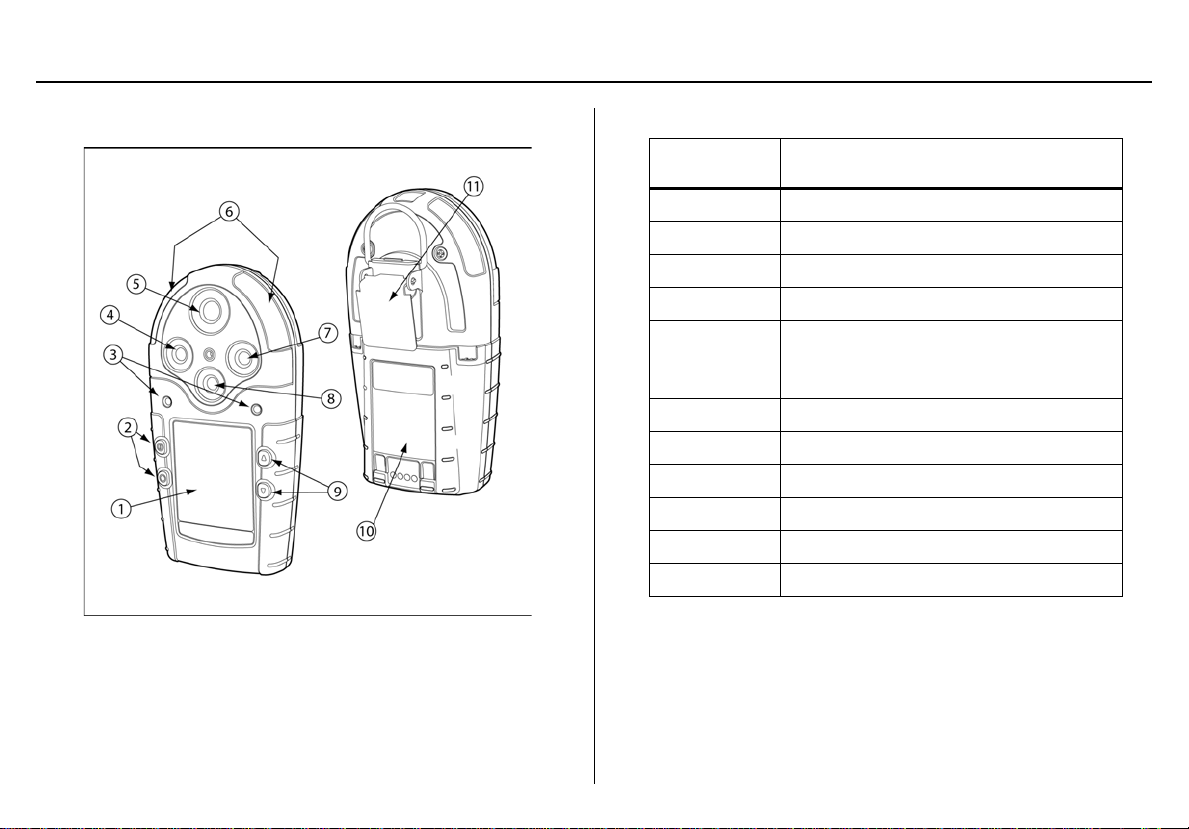
Figure 1. Parts of the GasAlertMicro 5/PID/IR
Table 4. Parts of the GasAlert Micro 5/PID/IR
Item Description
1 Liquid crystal display (LCD)
2 Pushbuttons
3 Audible alarms
4 Toxic 2 sensor
Toxic 1/PID sensor (Micro 5 PID)
5
6 Visual alarm indicators (LEDs)
7 LEL sensor
8 Oxygen sensor
9 Pushbuttons
10 Battery pack
11 Alligator clip
or
Toxic 1/IR (CO
) sensor (Micro 5 IR)
2
9
GasAlertMicro 5/PID/IR
User Manual
Screen Elements
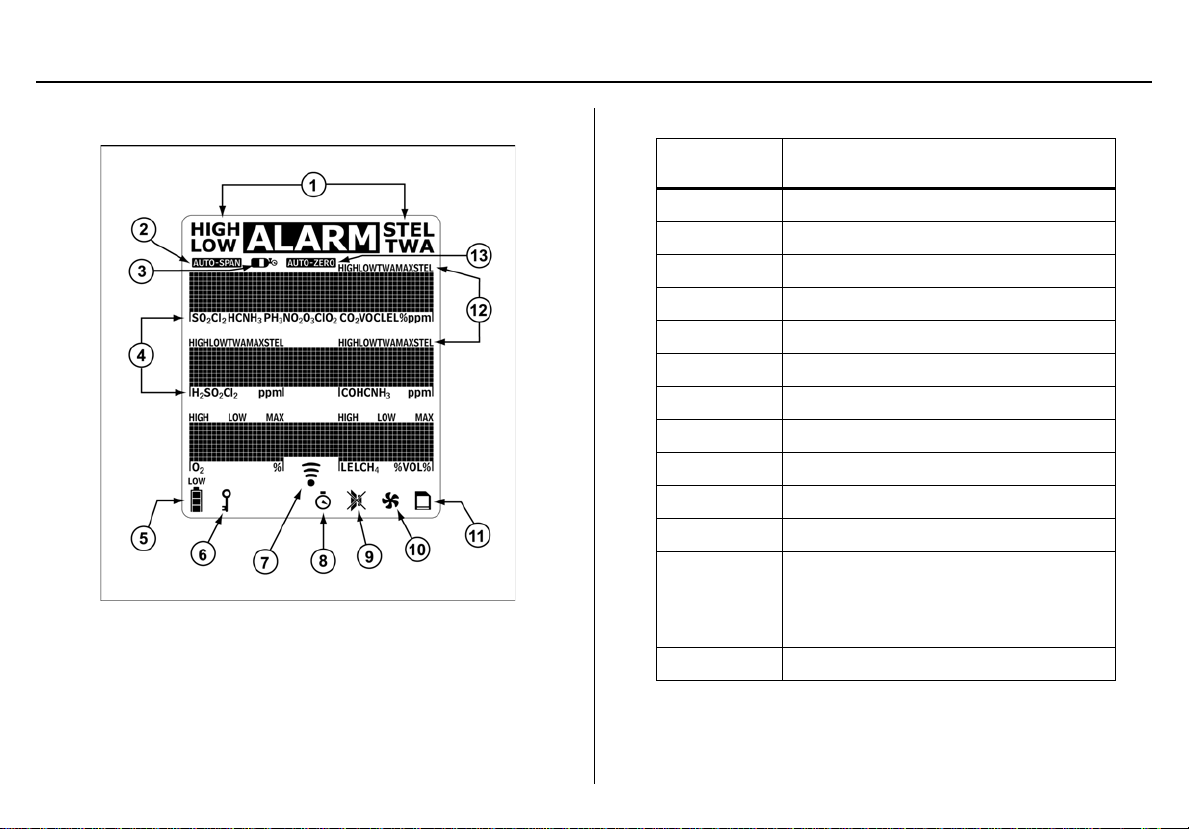
Figure 2. Screen Elements
Note
If enabled, the backlight automatically activates for 8 seconds
when there is an alarm condition and whenever there is
insufficient light to view the LCD. Any pushbutton reactivates
the backlight in low light conditions.
Table 5. Screen Elements
Item Description
1 Alarm condition
2 Automatically span sensor
3 Gas cylinder
4Gas type
5 Battery life indicator
6 Passcode lock
7 Data transmission
8Clock
9 Stealth mode
10 Pump indicator (optional)
11 MMC indicator (optional )
Alarm condition (low, high, TWA,
12
13 Automatically zero sensor
STEL, or multi alarm) or view TWA,
STEL and peak (MAX) gas exposures
10

Pushbuttons
Table 6. Pushbutton
Pushbutton Description
• To activate the detector press A.
A
• To deactivate the detector, press and hold A until the countdown is complete.
• To increment the displayed value or scroll up, press G.
• To enter the user options menu, press and hold G and H simultaneously until the countdown is complete.
GasAlertMicro 5/PID/IR
Pushbuttons
G
H
C
• To clear the TWA, STEL, and peak (MAX) gas exposure readings, press and hold C and G simultaneously
until the countdown is complete.
• To view the date and time, alarm setpoints (TWA, STEL, low, high) of all sensors, and the LEL/PID correction factor
(if applicable) press G.
• To decrement the displayed value or scroll down, press H.
• To initiate calibration and to define alarm setpoints, press and hold C and H simultaneously until the countdown
is complete.
• To view the TWA, STEL, and peak (MAX) gas exposure readings, press C.
• To acknowledge latched alarms, press C.
11
GasAlertMicro 5/PID/IR
User Manual
Activating the Detector
If using the pump module, attach it and the pump accessories prior to
activating the detector.
For illustrations and procedures, refer to the following:
• Installing the Pump Module
• Attaching the Sample Probe
• Replacing the Pump Filter
• Replacing the Pump Nozzle
• Attaching the Auxiliary Filter
Only activate the detector in a safe atmosphere that is free of
hazardous gas in an atmosphere of 20.9% oxygen.
To activate the de tecto r, press A.
Self-Tests
When the detector is activated, it performs several self-tests. Conf irm
the following tests occur.
If an error message displays during the self-test, refer to
Troubleshooting
.
.
Note
Note
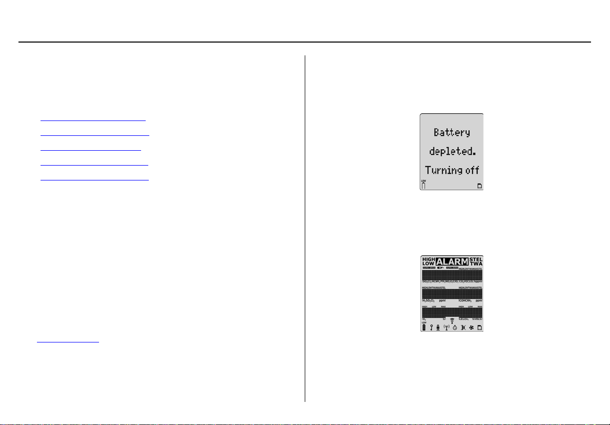
Battery Test
The detector performs a battery test during startup. I f the battery has
insufficient power to operate, the following screen di splays before
deactivating.
Replace the batteries and reactivate the detector.
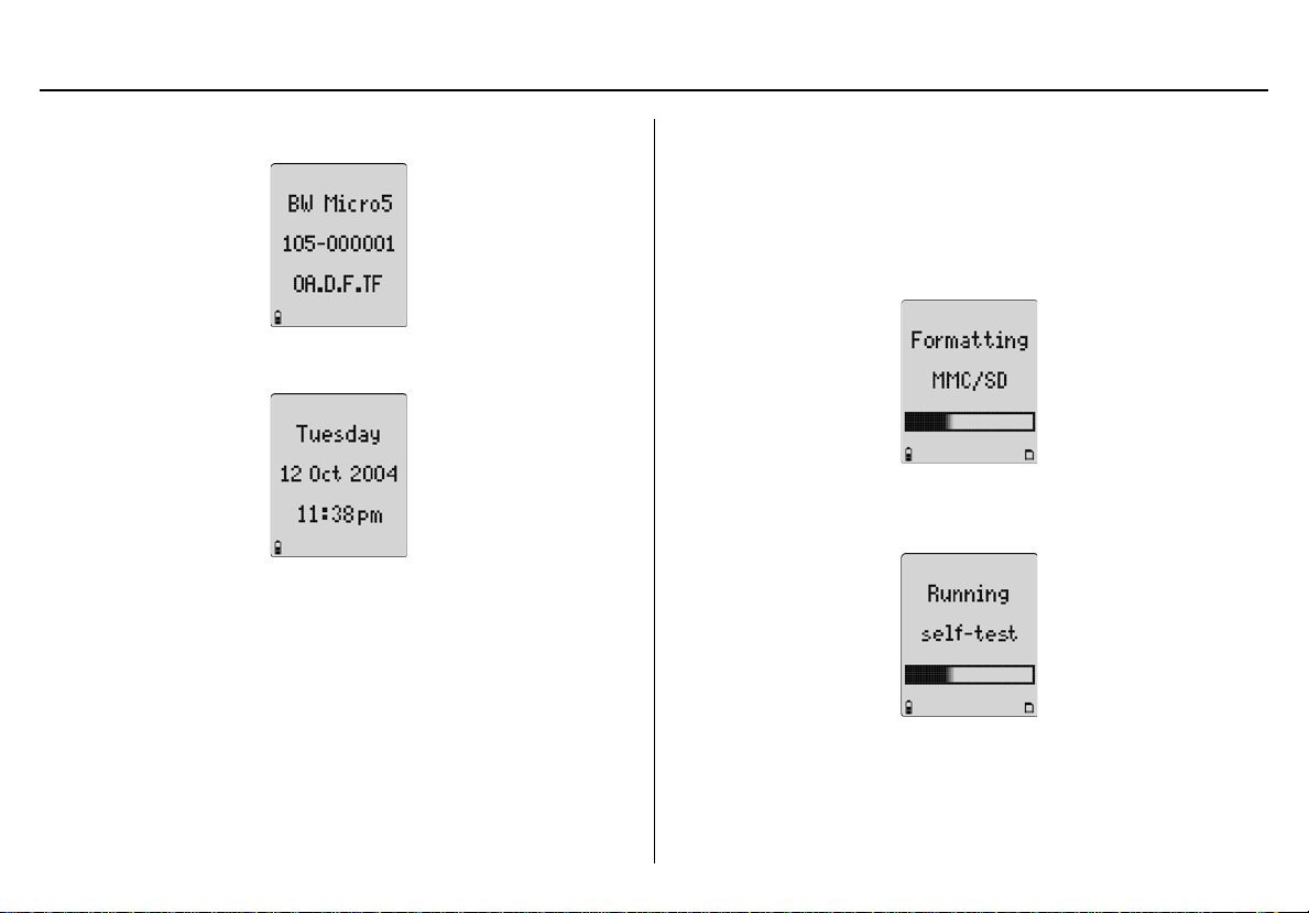
1. All of the LCD elements display simultaneously as the detector beeps, flashes, vibrates, and briefly activates the backlight.
12
GasAlertMicro 5/PID/IR
Activating the Detector
2. The version and serial number of the detector displays.
3. The date and time displays.
Datalogging (Optional)
4. If the detect or is a datalogging unit, it determines if
• a MultiMediaCard (MMC) or Secure Digital (SD) card is
inserted,
• the detector can communicate with the card,
• the detector supports the size of the card, and
• the card requires formatting.
Note
If there is a problem with the MMC/SD card, Datalogger
disabled displays. The detector then automatical ly continues
with the self-test.
If the card requires formatting, the following screen
displays as the card is automatically formatted.
5. The detector then runs a self-test to verify the sensors and
power supply are operating correctly.
13
GasAlertMicro 5/PID/IR
User Manual
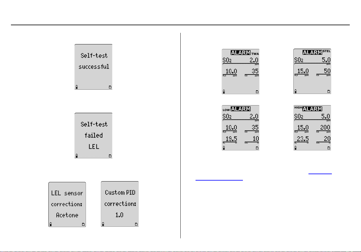
Self-test Successful: If successful, the following screen displays.
Self-test Unsuccessful: If a sensor fails the self-test, a warning
displays indicating which sensor(s) has failed.
6. If correction factors are set in the user options, the LEL or PID
(custom) correction factors display.
7. The TWA, STEL, low, and high alarm setpoints then
display in the following order (left to right).
TWA STEL
Low High
Note
The alarm setpoints may vary by region. Refer to Resetting
Gas Alarm Setpoints.
14
GasAlertMicro 5/PID/IR
Activating the Detector
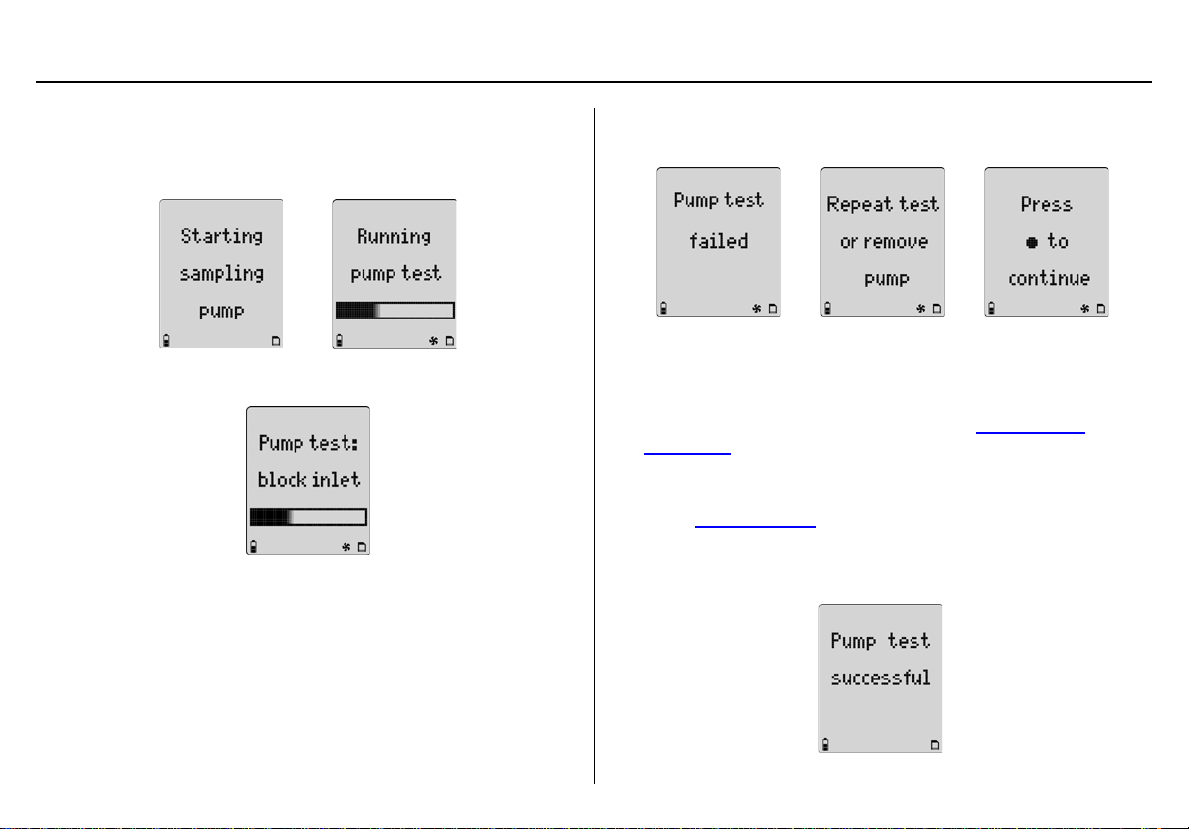
Pump Test
8. If the pump module is attached to the detector, the following
screens display.
When the following screen displays, block the pump inlet.
If the pump inlet is not blocked within 10 seconds or the pump
test fails, the following screens display.
If C is not pressed or the pump is not removed within
25 seconds, the detector performs the pump test again.
Note
The pump may require a new filter. Refer to Replacing the
Pump Filter.
If the pump alarm persists, remove the battery pack to deactivate the detector and then refer to the “Pump Operation” section of Troubleshooting
If the pump test is successful, the following screen
displays and the self-test continues.
.
15
GasAlertMicro 5/PID/IR
User Manual
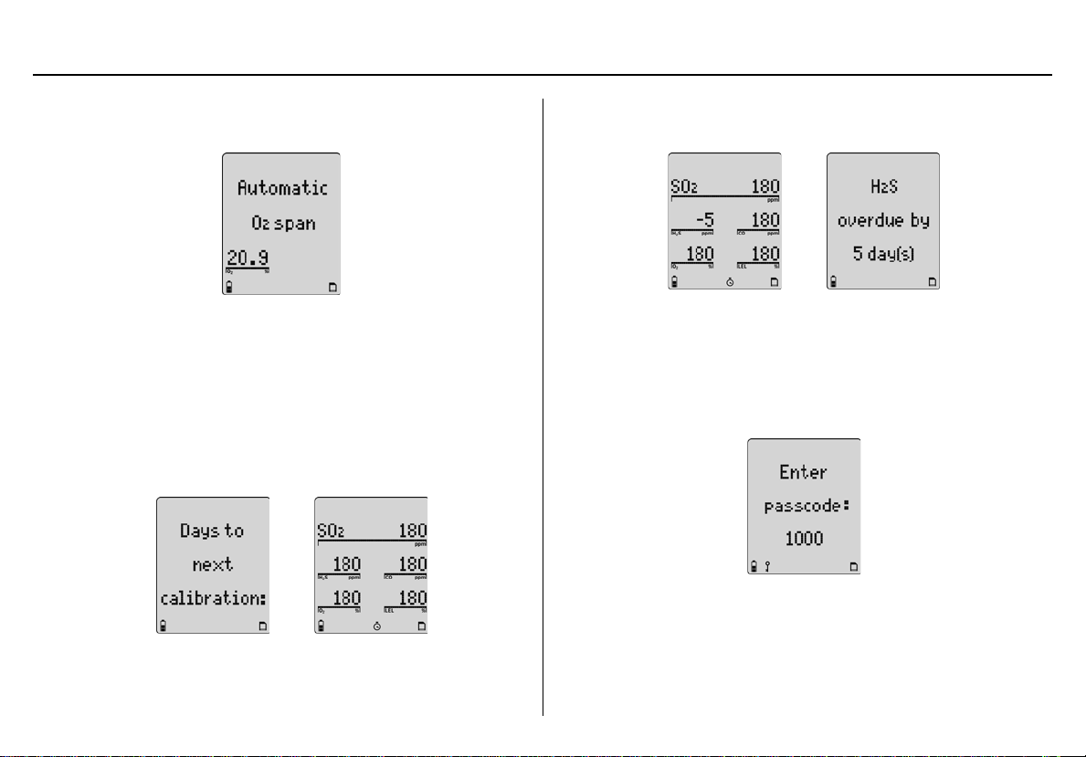
9. Unless disa ble d in user op ti ons, the ox ygen (O2) sensor is calibrated automatically.
If the calibration is successful, the detector beeps twice.
Note
If the automatic O
Automatic O
10. The number of days remaini ng before calibration is due displays for all sensors.
calibration feature has been disabled,
2
span disabled displays.
2
If any sensor is over due for calibration, the LCD displays the
name of the sensor and the number of days past due.
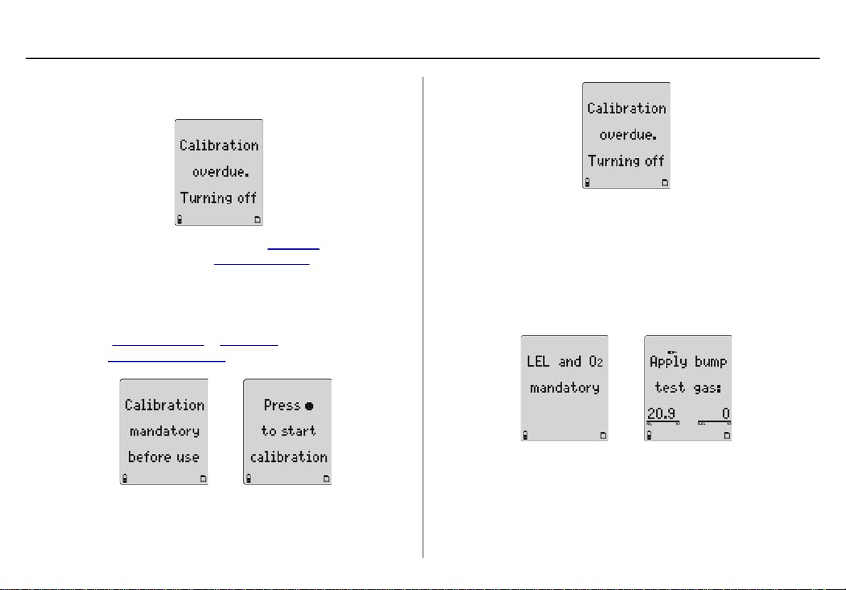
Due-Lock Enabled
The Due-lock option ensures that a passcode must be entered when
calibration is past due, otherwise the detector automatically deactivates.
11. If Due-Lock is enabled in the user options, the following
screen displays.
Enter the correct passcode and press C to confirm.
16
Note
If any sensor is overdue, Y displays continually until calibra tion
is performed.
If no passcode is entered, or it is entered inc orrect ly, the following screen displays.
To enable/disable this option, refer to Due-Lock
options menu. Also refer to Passcode Protect
in the user
.
Force Calibration Enabled
12. If Force cal (force calibration) is enabled in tech mode, calibra-
tion is mandatory before the detector enters normal operation.
Refer to Force Calibration
refer to Calibration Procedure
in Tech Mode to enable/disable, and
to calibrate.
GasAlertMicro 5/PID/IR
Activating the Detector
Bump Daily Enabled
a Caution
BW recommends that a bump test to all sensors be
performed every 24 hours prior to the beginning of the
work shift.
13. If Bmp Daily (bump daily) is enabled in tech mode, the follow-
ing screens display.
If C is not pressed to start calibration , the f ollowin g scre en d isplays and the detector deactivates.
If a bump test of the LEL and O
detector will deactivate.
Apply the LEL gas and then apply the O
percentage than the default 20.9%, such as 18 % O
sensor is not performed, the
2
(a higher or lower
2
).
2
17
GasAlertMicro 5/PID/IR
User Manual
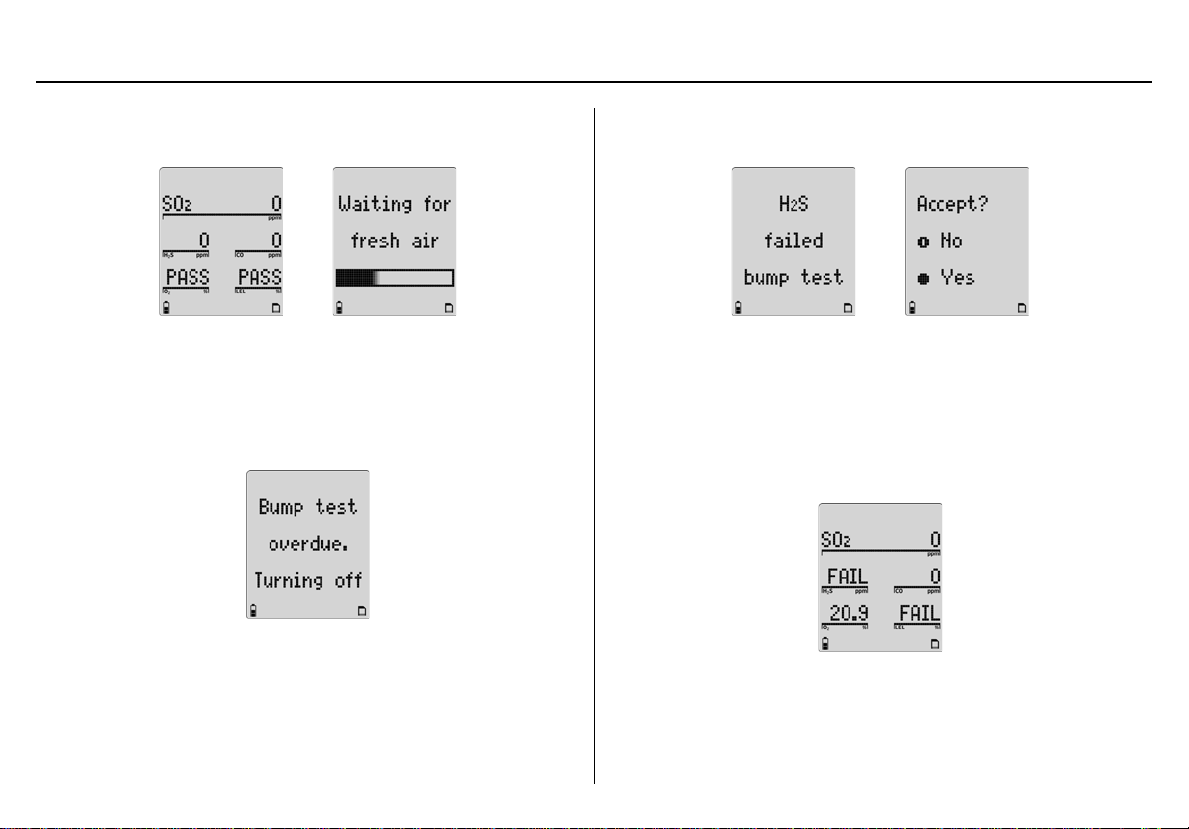
Successful Bump Tes t: If the bump test passes, the following screens
display.
The detector waits for the sensor(s) to clear (30 seconds) and then
enters normal operation.
Unsuccessful Bump Tes t: If the bump test is unsucce ssful or the bump
test is not performed, the following screen displays and the detector
deactivates.
If additional sensors require a bump test but are not mandatory, the
following screens display.
Press C Yes to accept and proceed to normal operation.
Or
If A No is pressed, or no buttons are pressed, the sensor(s) that is
past due displays as FAIL when the detector enters normal operation.
In the following screen example, only the SO
operational.
The self-test is now complete.
, CO, and O2 sensors are
2
18
 Loading...