

Page 1
BARKER & WILLIAMSON
6025 TECHNOLOGY DR
W MELBOURNE, FL 32904
321-676-8354
www.bwantennas.com
U.S. PATENT #4423423
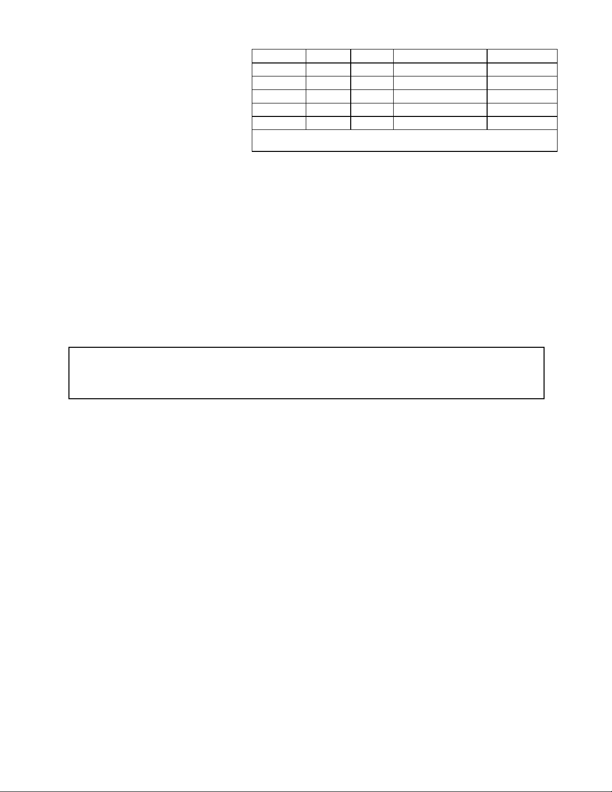
BROADBAND FREQ AGILE HF FOLDED DIPOLE ANTENNA
LEDOMLEDOMHTGNEL1:2<RWS1:3<RWS
N02-SDWB02-DWB tF02M01-02,zhM03-41M6,zhM45-03
N54-SDWB54-DWB tF54M01-04,zhM03-7M6,zhM45-03
N56-SDWB56-DWB tF56M01-57,zhM03-4M6,zhM45-03
N09-SDWB09-DWB tF09M01-061,zhM03-8.1M6,zhM45-03
N081-SDWB081-DWB tF081M01-061,zhM03-8.1M6,zhM45-03
esusannetnaDWB.srotcennocNdnaeriwleetssselniatsesusannetnaSDWB
.srotcennoc)FHU(932-OSdnaeriwdlewreppoc
The Barker & Williamson Broadband Folded Dipole Antenna is designed for continuous frequency operation over its specified range.
The antenna comes fully assembled and pretuned so no measuring or cutting is required. It is all weather rated at 1 KW PEP SSB/CW
ICAS (Intermittent Commercial and Amateur Service), and permits use of the full capabilities of today’s continuous coverage
transceivers. Its single feedline operation for all bands provides excellent performance for military, emergency management,
commercial, and amateur installations. Instant tuning with no moving parts allows continuous ALE operation. Installation will determine
the type of propagation, with skywave/groundwave combination, or just skywave for NVIS use. 1KW PEP Output power CCS (Continuous
Commercial Service) requires the HFT-1 balun and LD-9 matching unit.
Features include a high impact plastic housing for the balun and matching network. Feedline impedance is 50 ohms. Copperweld antennas
come equipped with an SO-239 (female) coax cable connector. Stainless steel antennas are equipped with an N female connector. The
antenna may be installed as a flat-top, inverted Vee or a sloper. For the best mid/long range omni-directional radiation, installation as a
shallow inverted Vee is suggested. Our FDMK mounting kit is available for inverted Vee, or other three pole installations. NVIS is performed
as a flat-top low to the ground. We offer complete rapid deployment kits for NVIS, with fiberglass poles and carrying bags. These antennas
are able to self-support the center in a two pole installation, except the 180 foot antenna which requires a three pole installation. Note that
a three pole installation will provide better wind and ice capability, as well as a longer life.
WARNING: Do not install where antenna conductors could come in contact with your utility wires. Do not install
over or under utility wires, as wire breakage could cause contact to occur. People and pets must not come in contact
with antenna conductors during transmit operation. Refer to FCC rules on determining a safe zone around the antenna.
Balun and balancing network may become hot during high power operation.
Planning: Determining How and Where to Install
Remember that any radio station is only as good as its antenna. Take the proper time and care to plan it out. A successful installation
requires attention to antenna height, surrounding objects, feedline choice, location and orientation.
(1) NVIS propagation is performed as a flat-top with height varying from ground level to approximately 12 feet. This height is
dependent on the ground (soil) conditions. It may be possible to lay the antenna on the ground in desert/low water table environments.
The B&W NVIS pole kits allow multiple heights. In NVIS installations a counterpoise will sometimes enhance performance. If you are
not getting enough distance from your NVIS setup, try raising the center of the antenna a few feet to make a very shallow inverted Vee.
(Appropriate NVIS daytime frequencies are approx 5-12 Mhz, nighttime are 2-4 Mhz.)
(2) Conventional propagation minimum clear height is recommended at 25 feet for operation down to approx 3.5 Mhz (ends 12
feet for inverted Vee or sloper), and 40 feet for 1.8 Mhz (ends 20 feet for inverted Vee or sloper). Less height does not disqualify operation,
but may require a tuner on the lowest frequencies. Also, propagation may be reduced with inadequate height on the lower frequencies.
(3) This is a non-grounded antenna, so surrounding "grounded objects" try to absorb your radiated wave on low frequencies.
This may result in poor SWR, and/or poor signal reports. "Grounded objects" include metal towers/poles, roofs, gutters, trees, and the
ground itself. When supporting from metal towers/poles, step off (or up) from the metal with a wood or PVC support arm 3 to 5 feet. Avoid
crossing over roofs when possible. When using trees for supports, try to stay clear of the branches.
(4) When installing in an attic or close to a roof, remember that gutters, power line, and conduit/pipe runs become antennas that
may cause coupling problems at certain frequencies. Attempt to stay perpendicular to such objects. Always keep the balun and balancing
network hanging in the air with proper support such as an FDMK, away from wood and insulation to avoid fire hazard.
(5) Use the proper feedline. Examples are RG-8 (thick), RG-213, 9913. Over 50% of installation problems are coax/connector
problems. Check your feedline (including new ones) with a dummy load placed at the antenna end of the coax. Transmit into the dummy
load and check for 1:1 SWR on all bands. Do not substitute an analyzer for this step. Thin coax such as RG-8X may be used up to 20 watts.
(1)
8/12
Page 2

(6) The location will usually be determined by trade-offs of height, available supports, and interfering objects. Sometimes,
multiple trials may be necessary to judge which installation is best. Unfortunately, HF is difficult to predict. Usually, adequate height
is favored over other parameters.
(7) Remember that the highest amount of energy is radiated at a right angle to the antenna wire, the minimum off the ends (when
the antenna is parallel to the ground). Consider this when selecting map orientation for your antenna. By using an inverted Vee, you may
change the angle of radiation, and therefor affect the distance of transmission at different frequencies. Put simply, the steeper (more vertical
than horizontal) an inverted Vee is made, the more it will favor DX, and tend to skip over local stations at low frequencies. We recommend
roughly 30 degrees angle down on a leg from horizontal for best general, overall results.
INSTALLATION INSTRUCTIONS
(1) Determine your supports, paying attention to best possible height , antenna configuration, and alignment. Trees, sides of a building,
utility poles, etc. make good supports. Do not install parallel to power lines if it can be avoided.
(2) Unpack the antenna. Lay it on the ground, the two rolls seperated and the components laying in the middle. DO NOT UNCOIL UNTIL
YOU ARE READY.
(3) Cut enough polyester rope ( 3/16" diameter ) and prepare ends as shown in Figure # 1.
(4) Uncoil one half of the antenna. Avoid twisting, kinking or springing by keeping the antenna taut during uncoiling. Let the shipping
tube rotate in your hands - do not pull the wire off the ends as it will kink.
(5) Install the rope as shown in Figure # 1. If you keep the top arm of the rope 1" - 3" shorter than the bottom arm , the antenna will hang
in a proper vertical position instead of rotating flat.
(6) Repeat steps # 4 and # 5 to the other side of the antenna.
(7) Attach your coax cable and raise the antenna up in the air. Again avoid twisting, kinking or springing.
(8) Run the coax to the station. Run the coax down to the ground, and then perpendicular to the antenna for as far as possible. If this
is not done properly, you will transmit onto the shield of the coax, causing high SWR and transmitter power cutback. Only use a sufficient
length of coax to reach the station
(9) Your antenna is ready for operation. It is broadband and pretuned at the factory for an average SWR of 1.4:1 to 2.0:1 in HF depending
upon the frequency used and surrounding objects, ground conditions, etc. You may find that in extremely bad locations the use of an
antenna tuner will be helpful. SWR of 2:1 to 3:1 should be expected on 6 meters without a tuner.
(2)
Page 3

This installation is not suitable
for the 180 foot antenna.
This installation is not suitable
for the 180 foot antenna.
(3)
Page 4

WIND AND ICE SURVIVAL
WIND 100 MPH
150 MPH WITH 3 POLE SYSTEM
ICE 40 LBS
80 LBS WITH 3 POLE SYSTEM
Barker & Williamson guarantees each product to be free from defects in material and
workmanship for 90 days from date of purchase. The warranty applies to the original
purchaser only, and we will repair or replace the product at our discretion. Under no
circumstances will Barker & Williamson be liable for any damages or consequential
damages arising from use or misuse of our products. Warranty is voided if product
is subject to misuse, neglect, accident, improperly installed or used in violation of the
instructions furnished by us. We reserve the right to make changes in design at any
time without obligation to update previously manufactured models. This warranty is
given in lieu of any other warranty, expressed or implied.
WARRANTY STATEMENT
(4)
 Loading...