

Page 1
B&W Trailer Hitches
1216 Hawaii Road / PO Box 186
Humboldt, KS 66748
P:620.473.3664
F:620.869.9031
See Limited Lifetime Warranty at
bwtrailerhitches.com/warranty
NOTE: We recommend reading instructions before beginning the installation.
RAM OEM Mount System Slider Hitch Installation Instructions
20,000 LBS. TRAILER WEIGHT
5,000 LBS. TRAILER TONGUE WEIGHT
Call or Email us for Installation Support
hitches@turnoverball.com www.bwtrailerhitches.com
1
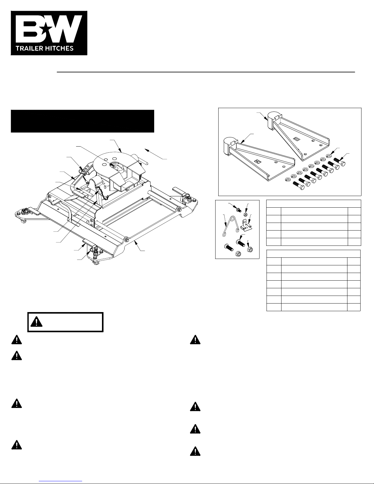
Model 3670
2
3
COUPLER JAWS
COUPLER CAM
HANDLE SAFETY PIN
COUPLER
CAM HANDLE
SADDLE HANDLE
COUPLER
TRUCK CAB
4
7
SADDLE
LOCKING PINS
PIVOT ARM
LATCH HANDLE
LATCH PIN
BASE ASSEMBLY
REQUIRED TOOLS
Installation of the Companion hitch requires a large torque wrench capable of
measuring 80 ft−lbs, a 3/4" socket, a 7/16", and 9/16" socket or wrench, a 7/32" allen
wrench, a pair of needle−nose pliers and a hammer.
Failure to comply with the safety information in these
WARNING
Read all installation and operating instructions along with all labels
before using this product.
Adding components to the chassis of any vehicle can be
hazardous. There is potential for damage to vehicle, injury from
tool usage and many other hazards. This installation must be
completed by someone who is aware of the hazards involved. This
person must be knowledgeable of proper safety procedures for a
vehicle installation of this nature, and for usage of the equipment
required to perform the installation.
Without proper knowledge, towing can be a dangerous activity.
Understand all the risks involved with towing before proceeding.
For information on towing safety, see
guide to Understanding Trailer and Towing Safety"
National Association of Trailer Manufacturers, www.NATM.com.
and your trailer manufacturer’s owner’s manual.
Do not exceed tow or tongue rating of coupler, tow or tongue
rating of hitch, or tow or weight ratings of truck or trailer. See
vehicle and trailer manufacturer information for ratings. Exceeding
these ratings may cause damage to towing components or loss of
attachment between the trailer and truck.
instructions could result in serious injury or death.
Additional caution must be used when towing a wedge car trailer.
Towing stability greatly depends on keeping the center of gravity
as low as possible. Load heavy cars over the axles. Never tow
with a single car on the front of the trailer. When towing a wedge
car trailer, never exceed speeds that are reasonable for the
roadway conditions (e.g. turns, going around a curve, etc.). Failure
to account for proper trailer center of gravity and speeds that are
reasonable for the roadway conditions may cause damage to the
truck, trailer, towing components, and loss of attachment between
the truck and trailer.
Do not modify this product in any manner. Doing so could alter its
"The Trailer Handbook: A
from the
integrity and lead to a loss of attachment between the trailer and
the tow vehicle.
Regularly check that all bolted connections are at the correct
torque specification. A visual inspection should be performed
before each time you tow.
Components of the hitch are heavy and cumbersome to handle.
Use proper lifting techniques when moving and handling parts.
8
65
9
10
BASE BOLT BAG (RVB3670)
ITEM DESCRIPTION QTY
1
Pivot Arm A
2
Pivot Arm B
3
1/2" Split Lock Washers
4
1/2" X 2" Cap Screw
COUPLER BOLT BAG (RCV3006)
ITEM DESCRIPTION QTY
5
Wire Torsion Spring
6
Mounting Clip
7
1/4" X 1/2" Cap Screw
8
1/4" Finish Nut
9
3/8" Button Head Cap Screw
10
3/8" Lock Nut
1
1
8
8
1
1
1
1
2
2
PAGE 1 of 5
Page 2
PREPARING TO INSTALL
Remove any debris and/or obstructions from the truck
bed, this includes any plastic caps which may be over
the attachment points. It may also be necessary to
remove the plastic grommets from around the mounting
points in order to fully seat the base down to the truck.
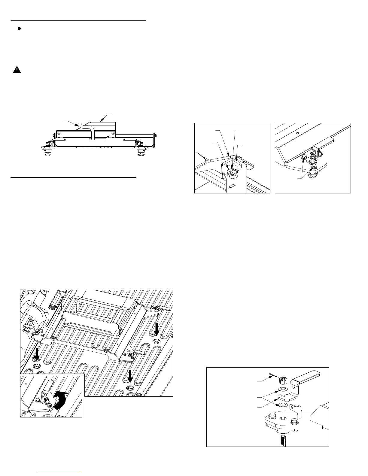
WARNING: Whenever the slider base is being
moved, the slider handle must be in the locked
position, and the carriage must be unable to slide,
see Figure A1. Failure to ensure that the handle is in
the locked position can lead to property damage, or
serious injury.
SLIDER HANDLE
IN LOCKED POSITION
Figure A1: View of driver side of Slider Base.
SLIDER CARRIAGE
2.
Each leg of the Companion base has an adjustable pilot
assembly which is attached to the foot with two 1/2" cap
screws, as shown in Figure B4. To adjust the pilot
assemblies that do not fit into the attachment points,
loosen both the 1/2" cap screws so the pilot assembly
can move freely, see Figure B4. Set the base over the
attachment points and adjust the pilot assemblies until
the pilot keys pass through the slot in the attachment
points and the pilot shoulders rest flat against the top of
the attachment points. When all the pilot assemblies
are aligned and inside the attachment points, push the
base towards the cab and use a tape measure to verify
that the base is approximately square with the truck
bed. Tighten any loose cap screws to 80 ft−lbs.
BASE
FOOT
PILOT
KEY
PILOT
SHOULDER
PILOT
ASSEMBLY
INSTALL SLIDER BASE
WARNING:
adjusted to fit the tow vehicle. Failure to properly
adjust the cams and handles may result in property
damage and/or personal injury.
1.
The Companion base will mount to four attachment
points in the truck bed. Remove any debris and/or
obstructions from the truck bed, this includes any
plastic caps which may be over the attachment points.
Remove the latch pins from each side of the base and
rotate the handles out, see Figure B1. Place the base
over the attachment points and carefully lower it until
the latch cams pass through the floor and the base
rests flat against the top of the attachment points.
The latch cams and handles must be
1/2" CAP
SCREW
Figure B3: View under base foot
3.
Prepare to adjust latch tension. Once the base is
Figure B4: View of base foot
in place, remove the cotter pins from each of the four
castle nuts. Engage the cams with each attachment
point by turning the latch handles back to their locked
position, see Figure B2. If a handle will not turn easily,
loosen the castle nut until the cam will freely turn and
engage the attachment point.
4.
Adjust the tension in the latch handle, for parts list
and visual guide refer to Figures B5 and B6.
With the handles in the latched position, tighten the
castle nut until snug to increase the tension on the
latch. Rotate the latch handle open and closed.
Tighten the castle nut slightly and rotate the handle
open and closed again. Repeat this process until you
feel the cam engage the attachment point while
closing the handle. The handle is set at the proper
tension when there is friction between the cam and
attachment point but the handle can still be closed by
hand without bumping, tapping, or otherwise forcing
the handle closed.
COTTER PIN
Figure B1:
View of unlatched base.
Figure B2: View of closed latch handle.
IMPORTANT: The attachment points may differ from
truck to truck. If the pilots fit into the trucks
attachment points you may skip Step 2 and continue
with Step 3. If the Companion base does not fit into
the attachment points proceed to Step 2.
FLAT WASHER
LATCH HANDLE
Figure B5: List of latch parts.
Adjustment instructions continued on next page.
PAGE 2 of 5
Page 3

COTTER PIN
LOOSEN
TIGHTEN
Figure B6: View of base leg.
WARNING:
Setting latch handle tension so that
excessive force is required to close the latch handles
may result in property damage and/or personal injury.
5.
With the base firmly held down and each latch handle
closed, replace the latch pins removed in Step 1.
NOTICE: Verify latch tension each time the
Companion base is placed in a truck, and periodically
before towing.
WARNING: Check the clearance between the truck
cab and the trailer in both the towing position and the
maneuvering position. Compare the measurement
taken from the center of the Slider Coupler to the cab,
to the measurement taken from the center of the king
pin to the farthest forward corner point of the trailer.
These measurements will allow you to see how much
clearance you will have between the cab and the
trailer while towing and turning.
CENTER OF
COUPLER
TO CAB
KINGPIN TO EDGE OF TRAILER
WARNING: Check the clearance between the bed
side and the underside of the front of the trailer and to
allow adequate clearance for the pitch and roll of the
trailer while towing.
WARNING: Parts of the trailer may strike the tailgate
when sliding the companion rearward. Check the
clearance between the tailgate and trailer components
such as the trailer tongue or pin box. Failure to check
clearance may cause property damage.
INSTALL LEVELING KIT
INSTALL PIVOT ARMS
1.
Mount the pivot arms using one of the six different
locations illustrated in Figure C1. These six locations
allow flexibility in coupler height and distance from the
cab. Choose a location so that your trailer will be as
level as possible and have adequate turning clearance
while in the towing position (with the slider in the
forward position). See warnings after step 2.
BED FLOOR TO TOP OF
COUPLER
HIGHEST
POSITION
(19")
MIDDLE
POSITION
(18")
LOWEST
POSITION
(17")
KINGPIN 2"
IN FRONT OF AXLE
POSITION CLOSEST TO CAB
KINGPIN OVER AXLE
POSITION FARTHEST FROM
CAB (ARMS REVERSED)
PIVOT ARM
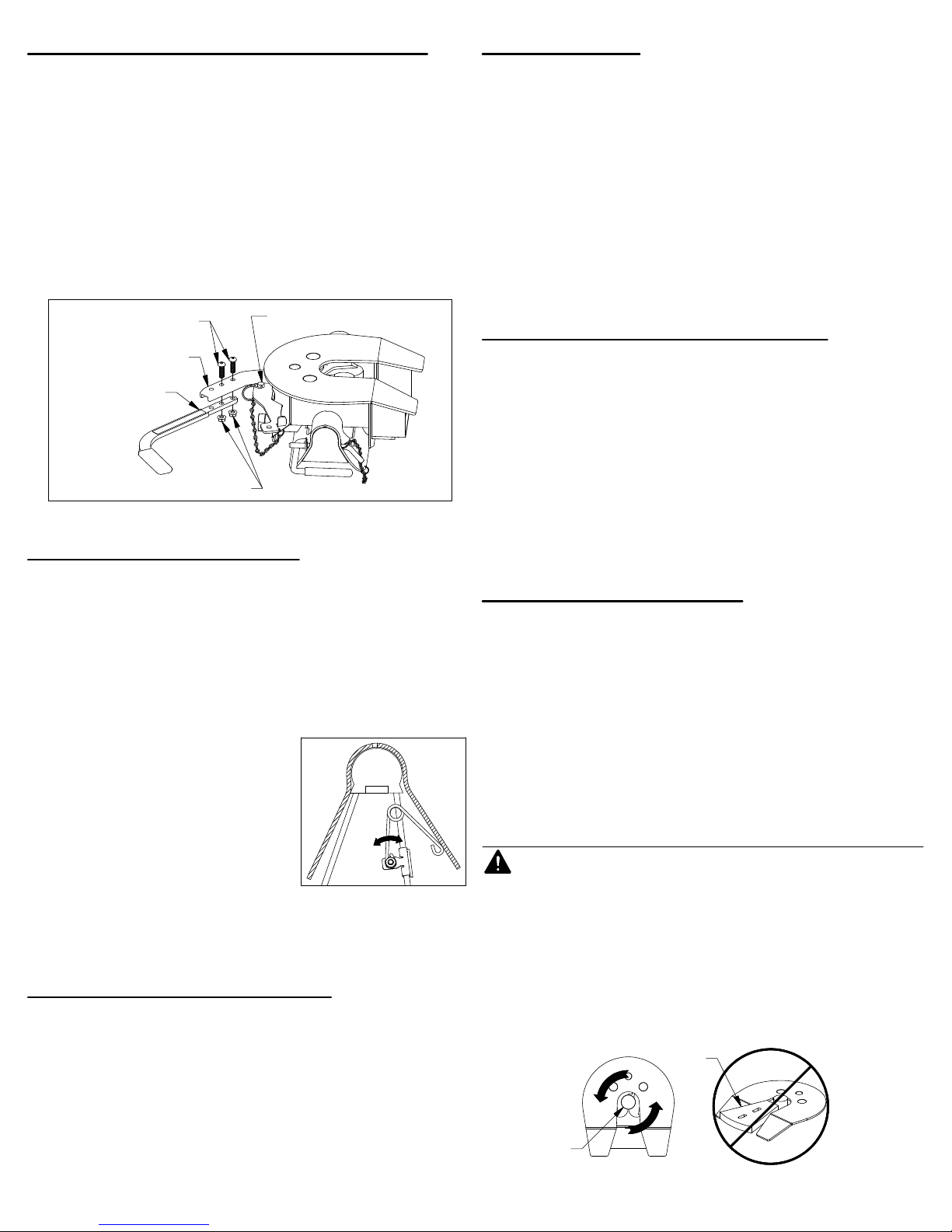
1.
Locate the 1/4" cap screw and nut, along with the wire
tension spring and mounting clip. Pass the 1/4" cap
screw through the mounting clip and the wire spring,
as shown in Figure D1. Thread the 1/4" lock nut onto
the 1/4" cap screw. Tighten the lock nut just enough
that the spring will stay in place but will still be able to
rotate around the bolt if needed, see Figure D2.
1/4" LOCK NUT
WIRE
SPRING
MOUNTING
CLIP
Figure D1:
Leveling kit parts.
2.
Locate the flange which will be closest to the truck cab
Figure D2:
Assembled leveling kit.
on the driver side pivot arm, see Figure D3. The clip
should be placed so that when the spring’s coil is in
line with the edge of the arm there will be 1/2" of
clearance between the bottom of the rubber bumper
and the top of the spring, see Figure D4. Drive the
clip securely onto the flange with a hammer.
DRIVER SIDE PIVOT ARM
CAB
1/2"
Figure C1: Cut away view of slider carriage arm positions.
2.
With the flat side of the pivot arm flat against the bolt
plate in the slider base, install four 1/2" x 2" bolts and
four 1/2" split lock washers for each arm. Torque each
bolt to 80 ft−lbs.
Figure D3: Base view.
Figure D4: Driver side pivot arm.
PAGE 3 of 5
Page 4
INSTALL COUPLER HANDLE
1.
Locate the two 3/8" x 1−1/4" button head cap screws
and the two 3/8" flanged lock nuts provided in a bolt
bag. Pull out the coupler arm and pin it with the
safety locking pin near the base of the arm as shown
in Figure E1.
CAUTION:
creates a pinch point. Use caution when installing the
handle to avoid injury.
Using the button cap screws and the lock nuts, attach
the coupler handle to the arm and tighten, see Figure
E1. Pull out the coupler cam handle safety pin.
3/8" BUTTON HEAD
Pulling the arm out away from the coupler
COUPLER CAM
CAP SCREWS
HANDLE SAFETY PIN
PULL TEST
Have the truck stationary with the emergency brake on,
the trailer wheels blocked and landing gear still resting
firm on the ground supporting the weight of the trailer.
Make sure no one is between the truck and trailer, return
to the cab of the truck. Release the emergency brake and
apply the trailer brakes. Try to pull the trailer forward with
the truck. If the trailer is properly hooked up, the wheel
blocks and trailer brakes should not allow the truck to
move forward. If trailer is not hitched correctly, the trailer
will separate from the truck. However, with the landing
gear resting firmly on the ground, it will support the trailer
and not allow it to drop or fall on the truck sides.
UNATTACHING TRAILER
COUPLER ARM
COUPLER
HANDLE
3/8" LOCKING FLANGE NUTS
Figure E1: View looking down at side of coupler head.
INSTALL COUPLER
1.
Lubricate the polyurethane bushings on top of pivot
arms with high grade lithium grease (available at your
local hardware/automotive store). Place the coupler
over the pivot arms. (The saddle handles should be
parallel with the Slider Base in the latched position.)
Place the saddle lock pins through the saddle, then
insert the hair pins through the holes in the end of the
saddle lock pins to secure the coupler to the pivot arms.
2.
Adjust the resting angle of
your coupler plate by rotating
the spring on the driver side
pivot arm. Pulling the top of
the spring away from the cab
will increase the angle of the
coupler plate. Set the angle of
the coupler so that head will
tilt away from the cab when
Figure F1: Cutaway view of
driver side pivot arm and saddle.
coupling, see Figure F1. Tighten
the 1/4" nut once the spring’s orientation is set.
ATTACHING TRAILER
Remove the coupler cam handle safety pin and rotate
the cam handle to the open position. Adjust the height
of the 5th wheel trailer so that the king pin plate is
slightly lower than the top of the coupler. Back the
truck towards the trailer, centering the trailers king pin
in the Coupler, until the king pin has engaged the
jaws. Ensure that the Coupler cam handle has
completely closed before inserting the cam handle
safety pin through the cam handle and the coupler.
Hook up brake and lighting connections before towing.
Lower landing gear and block the trailer wheels. Raise
the trailer until the tongue weight is removed from the
truck. Then, unpin the Coupler handle and rotate to the
open position to unlatch the jaws. If the jaws do not open,
readjusting the landing gear may relieve pressure and
allow them to open. Use the safety pin to lock the handle
in the open position and when you are sure that the
landing gear will support the trailer, move the truck
forward to release the jaws from the kingpin. The jaws
will always open when the pressure of the trailer is taken
off the Coupler as the truck pulls away.
UNINSTALL HITCH
To uninstall the Companion hitch, remove the saddle lock
pins, grab the saddle handles and lift to remove the
coupler from the pivot arms. To remove the Companion
base, remove the latch pins from each base leg and turn
the handles. Carefully lift and position the base out of the
attachment points.
NOTICE: Base latch handle tension and all bolted
connections should be checked regularly. The latches
must have the proper resistance when rotating, and bolts
must have proper torque. Always perform a visual
inspection before towing.
WARNING: Do not use the Companion 5th wheel
hitch with any device that changes the location of the
king pin pivot point. The king pin on your trailer must
rotate in the jaws of the Companion Coupler, see
Figure G3. Preventing the king pin from rotating
within the jaws of the Companion Coupler with a
wedge, see Figure G4, or any other device, such as a
Reese Sidewinder or Reese Revolution , could
result in property damage, serious injury or death.
KING PIN
PIVOT POINT
Top view of coupler head.
®
Reese is a registered trademark of Cequent Performance Products.
FIGURE G3:
®®
WEDGE
FIGURE G4:
Coupler Head with
locking wedge.
PAGE 4 of 5
Page 5
SLIDER OPERATION
WARNING: Use extreme caution when moving the
truck and trailer in the maneuvering position. Never
exceed 5 mph (roughly walking speed) when in the
maneuvering position, doing so may result in
property damage, serious injury or death.
CAUTION
: Use of the slider mechanism should only
be attempted while on smooth flat terrain.
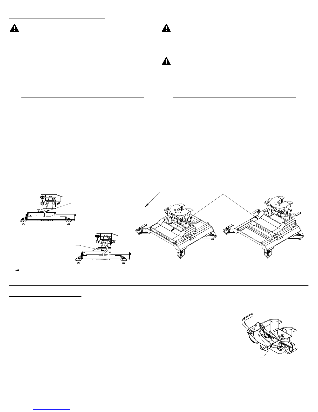
Moving from towing position to maneuvering
position. (Figure H3 to H4)
1.
While the trailer is coupled, set the trailer brakes
and/or chock the trailer wheels.
Pull the handle toward the rear of the truck to move it
2.
to the unlocked position
, shown in Figure H2.
Pull the truck forward slowly until the handle falls and
3.
is in the locked position
, shown in Figure H1.
Release the trailer brakes, un−chock the trailer and
4.
maneuver the trailer as needed.
WARNING: The maneuvering position is only
intended for parking maneuvers and not for towing.
Using the slider in any other capacity could result
serious injury or death.
WARNING
: Never hold on to the handle or force it in
any direction while the truck is moving. Failure to
stand clear of the handle when the slider is in
operation could result in serious injury.
Moving from the maneuvering position to the
towing position. (Figure H4 to H3)
5.
Once the trailer is satisfactorily positioned, set the
trailer brakes and/or chock the trailer wheels.
Pull the handle toward the rear of the truck to move it
6.
to the unlocked position
, shown in Figure H2.
Move the truck slowly in reverse until the handle falls
7.
and is in the locked position
, shown in Figure H1.
Release the trailer brakes and un−chock the trailer.
8.
SLIDER LOCKING HANDLE
Figure H1: Side view of Slider Base.
LOCKED HANDLE POSITION
SLIDER LOCKING HANDLE
TRUCK CAB
Figure H2: Side view of Slider Base.
UN−LOCKED HANDLE POSITION
HELPFUL TIPS:
Approximately 15%−25% of the trailer weight should
be on the hitch.
The height of the king pin box and pivot arms should
be adjusted so that the trailer is approximately level
for towing.
Allow adequate clearance between the bed side and
the underside of the front of the trailer for pitch and
roll of the trailer.
Lubricate top surface of coupler with multi−purpose
automotive type chassis grease or use a nylon lube
plate to provide a lubricated surface.
Copyright 2018, B&W Custom Truck Beds, Inc. ALL RIGHTS RESERVED
TRUCK CAB
Figure H3: View of Slider Base with
the Carriage in a forward position.
TOWING POSITION
SLIDER CARRIAGE
Figure H4: View of Slider Base with
the Carriage in a back position.
MANEUVERING POSITION
Grease jaws with multi−purpose automotive type
chassis grease.
Grease the saddle through
the grease zerk approximately
every six months with
multi−purpose grease. This
allows the coupler to pivot
freely, see Figure J1.
GREASE ZERK
Figure J1: Underside view of Coupler Head
RVK3670 (pn 3670−101) 07 26 2018
PAGE 5 of 5
 Loading...