

Page 1
<THESE INSTRUCTIONS MUST BE GIVEN TO THE END USER>
B&W Trailer Hitches
1216 Hawaii Rd / PO Box 186
Humboldt, KS 66748
P:800.248.6564
F:620.869.9031
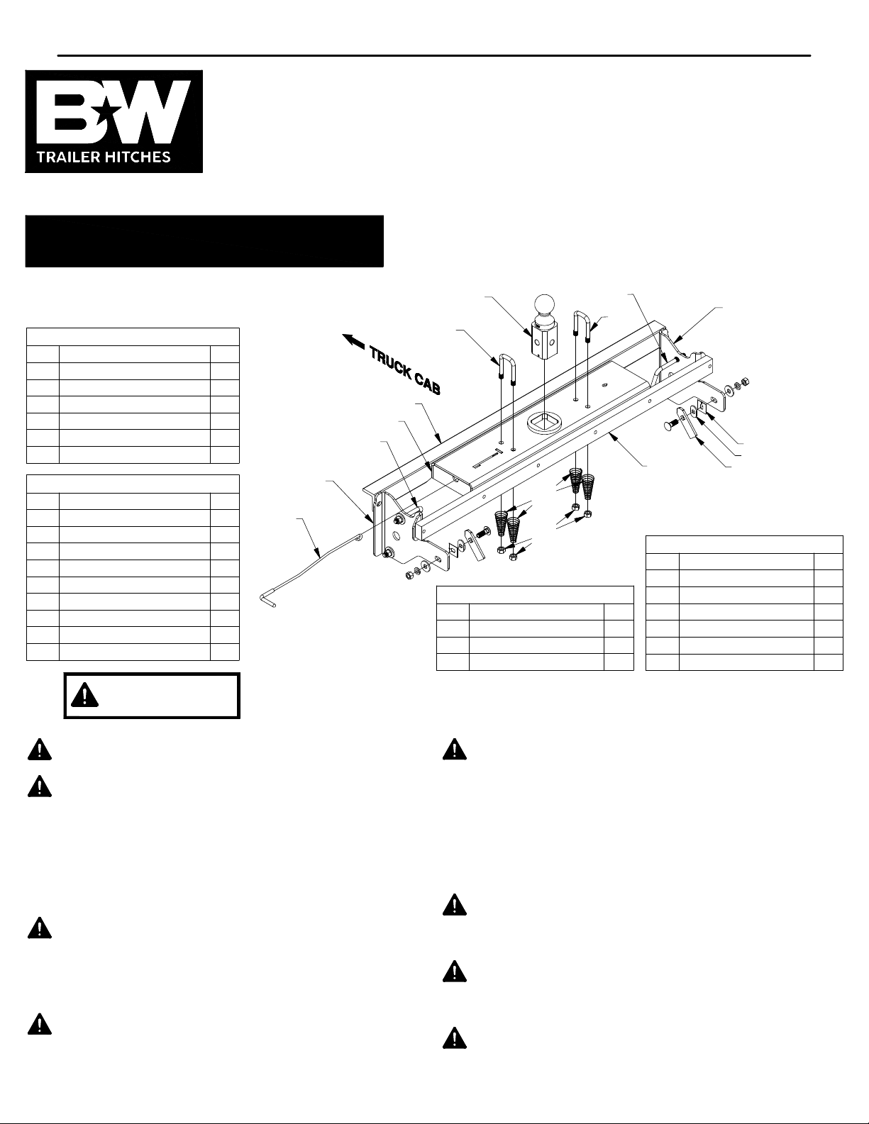
Turnoverball Gooseneck Hitch Installation Instructions
®
See Limited Lifetime Warranty at
bwtrailerhitches.com/warranty
Call or Email us for
Installation Support
hitches@turnoverball.com
bwtrailerhitches.com
MODEL 1019
2019 CHEVROLET & GMC 1500 Short Bed Trucks
12
5
3
Safety Chain Kit Bolt Bag
ITEM
12
1/2" U−Bolt
13
Conical Springs
14
1/2" Lock Nut
1
1
1
5/16" X 3/4" Carriage Bolt
5/16" X 3/4" Cap Screw
5/16" Lock Nut
Excludes 2019 Chevy LD & GMC Limited 1500 Trucks.
(call B&W for details concerning other bed sizes.)
Mounting Kit Box (GNRM1019)
ITEM
1
2
3
4
5
Fish Wire
ITEM
6
7
8
1/2" X 1−1/2" Carriage Bolt
1/2" X 1−1/2 Cap Screw
1/2" Finish Nut
1/2" Lock Washer
1/2" Flat Washer
O−Ring
DESCRIPTION QTY
Driver Side Plate
Passenger Side Plate
Rear Cross Member
Front Cross Member
1/2" X 5−1/2" X 4−1/4" U−Bolt
Mounting Kit Bolt Bag
DESCRIPTION QTY
1/2" Retainer
1/2" Frame Bushing
1/2" Locking Strap
12
12
18
14
1
1
1
1
2
2
1
2
2
2
2
1
11
10
12
4
9
5
13
14
Center Box (GNRC919)
ITEM DESCRIPTION QTY
9
Center Section
10
2−5/16" Ball
11
Latch Pin Handle
2
6
7
8
DESCRIPTION QTY
2
4
4
1
1
1
Failure to comply with the safety information in these
WARNING
Read all installation and operating instructions along with all labels
before using this product.
Adding components such as a Turnoverball hitch to the chassis of
any vehicle can be hazardous. There is potential for unexpected
combustion of fuel, electric shock, burns, shifting or falling of
unstable vehicle, damage to vehicle, injury from tool usage and
many other hazards. This installation must be completed by
someone who is aware of the hazards involved. This person must
be knowledgeable of proper safety procedures for a vehicle
modification of this nature, and for usage of the equipment
required to perform the installation.
Without proper knowledge, towing can be a dangerous activity.
Understand all the risks involved with towing before proceeding.
For information on towing safety, see
Guide to Understanding Trailer and Towing Safety"
National Association of Trailer Manufacturers, www.NATM.com
and your trailer manufacturer’s owner’s manual.
Do not exceed tow or tongue rating of coupler, tow or tongue
rating of hitch, or tow or weight ratings of truck or trailer. See
vehicle and trailer manufacturer information for ratings. Exceeding
these ratings may cause damage to towing components or loss of
attachment between the trailer and truck.
instructions could result in serious injury or death.
"The Trailer Handbook: A
from the
Additional caution must be used when towing a wedge car trailer.
Towing stability greatly depends on keeping the center of gravity
as low as possible. Load heavy cars over the axles. Never tow
with a single car on the front of the trailer. When towing a wedge
car trailer, never exceed speeds that are reasonable for the
roadway conditions (e.g. turns, going around a curve, etc.). Failure
to account for proper trailer center of gravity and speeds that are
reasonable for the roadway conditions may cause damage to the
truck, trailer, towing components, and loss of attachment between
the truck and trailer.
This product was designed to fit vehicles in their original, "as
manufactured" condition. Compatibility with vehicles having
replacement parts, or other modifications is not guaranteed.
Inspect vehicle for modifications before installation of this product.
The Turnoverball hitch comes equipped with a 2−5/16" ball.
Trailers towed with the ball provided must have a 2−5/16" coupler.
Towing with a larger coupler could cause loss of attachment
between the trailer and the tow vehicle.
Do not modify this product in any manner. Doing so could alter its
integrity and lead to a loss of attachment between the trailer and
the tow vehicle.
PAGE 1 of 7
Page 2
PREPARE TO INSTALL
NOTE: Remove all parts from the packaging and
familiarize yourself with all the parts and tools
required. Use the parts list on the front page to verify
that all parts and hardware are present.
Installation of the Turnoverball hitch requires several
common tools and a few specialized tools. Below is a
listing of equipment used during a typical installation.
TOOLS REQUIRED
Impact wrench or ratchet with 3/4",
10mm, & 13mm sockets.
1/2" & 3/4" Box end wrenches
Marking tool ( pencil or permanent marker)
4" hole saw Flashlight
Drill with 1/2" bit Eye protection
Ear protection
Pry Bar
Tape measure
Lifting Device Pilot hole Bit
Screw driver with T15 and T25 bits.
1.
Determine cab clearance. The Turnoverball hitch is
designed so that the ball can be inverted and stored
below the surface of the truck bed while not in use.
The ball location is determined by this design feature
and the truck geometry. Measure the trailers to be
towed with this hitch to be sure that the location of the
2−5/16" ball listed in Step 11 will provide ample turning
clearance between the nose of the trailers and the cab
of the truck.
Cab clearance on short bed trucks is very limited
when towing certain trailers. Failure to ensure that
there will be adequate clearance, may result in
significant property damage, or serious injury.
2.
Position the vehicle.
Installation of the hitch requires
the installer to be under the truck bed in the area of
the rear axle. Lifting the vehicle makes this area more
accessible to the installer, and improves the
installation process.
WARNING: Lift vehicle using only equipment
designed for lifting and positioning vehicles for
service. Failure to do so may result in property
damage, serious injury, or death.
Remove the spare tire.
3.
Following the vehicle
manufacturer’s instructions, remove the spare tire.
4.
Remove the spare tire heat shield.
bolts attaching the spare tire heat shield to the frame
of the truck with a 13mm socket or wrench. Set the
heat shield aside for later re−installation.
5.
Prepare a lifting device (optional).
of the device is to safely hold the hitch in position
during part of the installation.
See Figure A1 for an example.
A simple mechanical
lifting device is available
for purchase from B&W.
Torque wrench
Remove the six
The purpose
Figure A1.
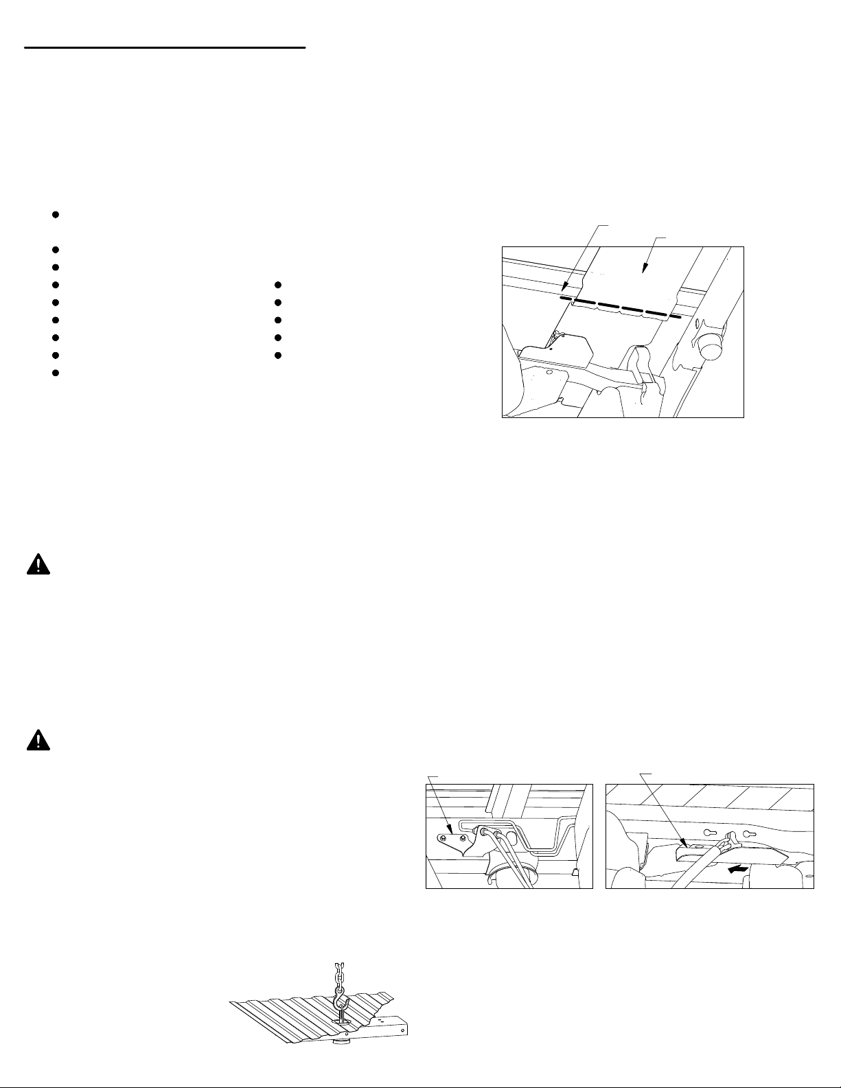
6.
Remove and discard the heat shield above the
rear axle.
A section of the exhaust heat shield will
need to be removed. Locate the bed cross member
that is directly over the axle, see Figure A2. The
section of heat shield in front of this cross member
will have to be removed. Cut along the cross member
with tin snips or another suitable tool. Make sure that
none of the heat shield is protruding past the front of
the cross member. Remove the T25 Torx screws
holding the front of the heat shield to the truck.
Discard the forward section of the heat shield when it
has been removed.
Figure A2: View looking up at bottom of bed above axle.
7.
Lower the exhaust (Optional).
CROSS MEMBER
C
U
T
L
I
N
E
HEAT SHIELD
To ease in the
installation of the center section, un−attach the rear
most tail pipe hangers from the frame and allow the
exhaust to hang freely. Re−attach the exhaust
brackets after installation is complete.
Un−attach brake and wiring brackets.
8.
Two brackets
are attached to the frame in locations that will interfere
with the installation. Using a 10mm socket or wrench
un−attach these brackets and allow to hang during
installation. These brackets will be re−attached when the
installation is complete. The first bracket holds two
brake lines on the inside of the driver side frame just
behind the rear axle, see Figure A3. The second
bracket holds wiring and is attached to a rectangular
frame cross member in front of and above the
differential. Loosen the connection and slide the bracket
to the driver side and unhook from frame. Allow to hang,
see Figure A4.
BRAKE LINE BRACKET (FIRST)
Figure A3.
9.
Disconnect wiring harness.
WIRING BRACKET (SECOND)
Figure A4.
Locate the wiring
harness running along the top of the passenger side
frame rail above the rear axle. Detach the plastic
connector closest to the shock bracket from the
frame. Pull the wiring down off the top of the frame,
towards the inside, to make space for the forward
cross member to sit on top of the frame. This wiring
will be left loose during and after the installation.
PAGE 2 of 7
Page 3
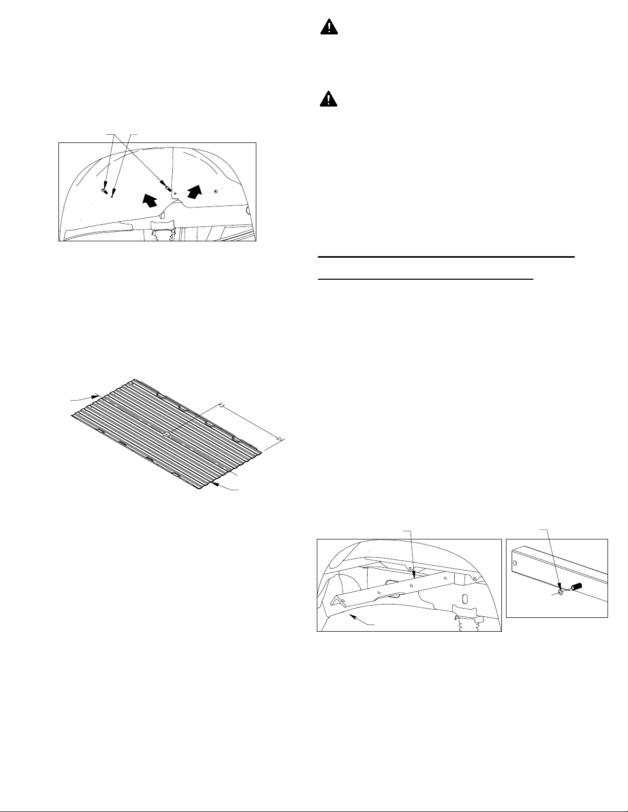
10.
Un−attach the wheel well liners.
Check for the
presence of flexible wheel well liners in the truck
wheel wells. If present, two T15 Torx screws will need
to be removed so that the liners can be folded up and
allow the cross members and side plates to be
installed, see Figure A5. Remove the screw retainer
from forward most hole using a screw driver. It will be
replaced after the hitch is installed.
T−15 SCREWS
SCREW RETAINER LOCATION
Turnoverball hitch components are heavy and
may be cumbersome to handle. Failure to use
proper lifting techniques and caution when
handling these items could result in serious
injury.
Most trucks have fuel lines, brake lines, electrical
wires or other vehicle systems located along the
frame rails or in the general area where B&W
Turnoverball hitches install. Carefully examine the
locations of these systems before installation.
Make certain that these are not damaged during
positioning hitch components, drilling holes, or
tightening fasteners. Damage to these systems
may result in property damage, serious injury, or
death.
Figure A5: View looking into driver side wheel well.
11.
Mark the 4" hole location. Using a tape measure
hooked over the rear edge of the bed (at tailgate end),
measure the location for the hole as shown in Figure
A6. Next, locate the center of the bed by measuring
the distance between the wheel wells and dividing by
two. The center of the hole will be at the intersection
of the center of the bed and the first distance
measured.
CENTER OF
TRUCK BED
FIGURE A6
4" HOLE LOCATION
SHORT BED (BED LESS THAN 8’ LONG) − 44 1/8"
4
"
H
O
L
E
L
O
REAR OF
TRUCK BED
IMPORTANT: The hitch is designed to install only at
the described location. Failure to place the 4" hole
precisely may result in added difficulty during
installation or property damage.
IMPORTANT: If the bed is equipped with a plastic bed
liner, the hole may be cut through both the liner and
the bed. However, the center of truck bed may be
more difficult to locate, and the mark may be harder to
hit if the liner slides or moves. Failure to cut the hole in
the correct location may adversely affect the install
and may result in property damage.
INSTALL CROSS MEMBERS
AND CENTER SECTION
1.
Install front cross member.
side wheel well, orient the front cross member (angle
iron) so that the heel of the angle is up and the flange
with the holes is towards the back of the truck, see
Figure B1. Pass the cross member between the bed
and the frame until it rests on the passenger side
frame. Roll the cross member so that the flange with
the holes is vertical. Install a 1/2" X 1−1/2"cap screw
into the second hole from the driver side of the cross
C
A
T
I
O
N
member with the threads towards the back of the
truck. Install the rubber O−Ring onto this bolt to keep
it in place during installation, See Figure B2. Push
the passenger side of cross member forward until it
hits the shock bracket. Push the driver side of the
cross member forward to make extra room for the
center section to be installed.
HEEL OF THE ANGLE
FRONT OF TRUCK
Figure B1: View looking into wheel well.
Starting in the driver
O−RING
Figure B2.
IMPORTANT:
If your truck has a spray−in bed liner
you will need to take this into account when you are
measuring, and add the thickness of the applied liner
that has been sprayed over the end of the bed.
12.
Cut the 4" diameter hole.
Cut the hole in the marked
location using a 4" hole saw or by marking out the 4" hole
and using a saber saw equipped with a metal cutting
blade. Remove any burrs created while cutting hole.
Continued on next page...
PAGE 3 of 7
Page 4

2.
Install center section. Starting behind the differential
under the truck, hold the center section so that the top
of the center section is facing towards the back of the
truck and the latch pin handle is on the driver side,
see Figure B3. Position the center section over the
differential and axle and move it towards the driver
side between the frame and the axle. Move the
center towards the driver side far enough that the
passenger side of the center can be lifted up past the
exhaust, see Figure B4. Roll and lift the center up
towards the passenger side of the truck so that the top
of the center is towards the bed and the passenger
side of the center is over the exhaust. Lift the driver
side of the center up and forward so that it is
positioned over the fuel tank.
4.
Attach the center to the cross members.
center section so that the raised portion on the top of
the center is through the 4" hole drilled in the bed
earlier. Secure with a lifting device if available. Slide
the front cross member back against the center
section so that the bolt installed previously in the front
cross member goes into the center section slot directly
across from it. Line up the rest of the holes and attach
the two members with 1/2" x 1−1/2" long cap screws,
flat washers, lock washers, and nuts. Insert four 1/2" x
1−1/2" bolts, with flat and lock washers installed,
through the rear leg of the center section into the
threaded holes of the rear cross member, see Figure
B5. Leave these bolted connections loose, engaging
only 3−4 threads, for the time being
.
Lift the
Figure B3: View looking up over axle.
CAUTION:
Plastic components located on top of the
Figure B4: View looking up over axle.
fuel tank can be easily damaged during the installation
of the hitch components. Care must be taken when
positioning the front crossmember and center section.
3.
Install rear cross member. Starting in the driver side
wheel well, orient the cross member so that the bar is
vertical, and the threaded holes are closer to the top
of the bar. Pass the cross member between the bed
and the frame until it rests on the passenger side
frame, see Figure B5. Center the cross members
between the bed flanges on either side of the truck.
Push the cross member back against the bed cross
member to make room for the center section.
BED FLANGE
Figure B5: View looking under the truck bed.
INSTALL SIDE PLATES
1.
Position the U−bolts. Each side plate will utilize a
U−bolt for attachment to the frame. On the driver side,
the U−bolt will need to be passed under the brake lines
on the side of the frame, see Figure C1. On the
passenger side the U−bolt will need to be positioned
under the wiring that runs over the top of the frame,
see Figure C2. Move the U−bolts so that they hang
roughly 8 inches in front of the axle center line.
U−BOLT
BRAKE LINES
WIRING HARNESS
U−BOLT
Figure B5: View looking into driver side wheel well.
View looking at driver side of frame
Figure C1:
View looking at passenger side of frame
Figure C2:
Continued on next page...
PAGE 4 of 7
Page 5

2.
Install frame studs. Locate the oval hole on the
outside of the frame directly over the center line of the
axle. To begin, place a 1/2" x 1−1/2" carriage bolt
through a locking strap. Next, thread a fish wire onto
the end of the carriage bolt. From the inside of the
frame pass the fish wire though the oval hole located
earlier. While holding the fish wire on the outside of
the frame push the locking strap and carriage bolt into
the frame, see Figure C3. Continue pulling on the fish
wire until the threaded portion of the bolt is sticking out
of the frame. Turn the carriage bolt until the square
shoulder engages the square hole of strap. Before
removing the fish wire, thread the oval frame spacer
on the carriage bolt and into the oval slot. Remove
the fish wire and thread a bolt retainer on the carriage
bolt to hold the bolt in place. Repeat this step on other
side of the truck.
SECURE HITCH
1.
Square the hitch. Start by hand tightening each of
the bolts attaching the center section to the cross
members. Next, with a tape measure, check the
distance between the Turnoverball hitch and the
nearest bed cross member. The distance between the
hitch and the cross member should be consistent on
the driver side and the passenger side of the hitch,
see Figure D1.
BED CROSS MEMBER
REAR CROSS MEMBER
Figure D1: View looking at driver side plate.
Figure C3: View looking at driver side frame.
3.
Install the side plates.
Pass the side plates over the
U−bolts and stud placed in the frame. Secure each
side plate with flat washers, lock washers, and nuts,
see Figure C4. Attach the front flange of the side
plate to the front angle cross member by placing a
1/2" X 1−1/2" bolt though the front cross member, then
secure to the side plate with a lock washer and nut.
Next, attach the side plate to the rear bar by placing a
1/2" X 1−1/2" bolt with a lock washer through the side
plate flange and threading it into the rear cross
member, see Figure C5. Leave these bolted
connections loose for the time being.
IMPORTANT:
The hitch must be square in the truck.
If the center section is not parallel with the axle,
certain accessories to the Turnoverball hitch will not
be square with the truck.
2.
Tighten the center section bolts. Tighten each of
the eight bolts attaching the center section to the
cross members. Torque each bolt to 110 ft. lbs.
Tighten the side plate bolts.
3.
With the hitch squared
and firmly against the frame, tighten each of the
bolted connections in the side plates until snug in this
order: 1st, tighten the hardware attaching the side
plates to the cross members. 2nd, tighten the nuts
attaching the side plates to the frame studs installed
inside the frame. 3rd, tighten the U−bolt nuts to the
frame. Once all the hardware is snug, torque the
bolts in the side plate ears 110 ft. lbs. Tighten the
side plate frame stud connection to 110 ft. lbs.
Tighten both side plate U−bolts alternating between
the top and bottom threads so that the U−bolt is
secured evenly. Torque nuts on U−bolts to 40 ft. lbs.
Figure C4: View looking is driver side wheel well.
Figure C5.
PAGE 5 of 7
Page 6

INSTALL LATCH PIN RELEASE
INSTALL SAFETY CHAIN U−BOLTS
HANDLE
IMPORTANT: The latch pin will not function properly
if handle is not installed correctly.
1.
Cut access hole though liners. If truck is equipped
with wheel well liners, an access hole needs to be cut
in the liner. Draw a line on the liners, between the two
holes of the screws that were removed. Drill a pilot
hole on the line 8−3/4" forward of the rear hole. Make
sure this pilot hole lines up with the latch pin
mechanism on the center. Use a hole saw or other
method to cut a 1" to 1.5" diameter hole in this
location.
2.
Install handle. Install the latch pin release handle by
inserting it , from the outside of the truck, through the
slot in the end of the center section on the driver side
of the truck. Align the handle eyelet with the square
hole in the latch pin so the handle is in line with the
latch as shown in Figure E1.
3.
Secure Handle. Secure the handle to the pin with the
5/16" X 3/4" carriage bolt and 5/16" locking flange,
see Figure E2. Note: The included 5/16" cap screw
can replace the carriage bolt if wrench access on the
"cab side" of the handle is limited. Tighten the nut until
it is secure. When tightening the handle, position it so
that it will not rub on the center, the side plate, the bed
flange, or the liner. Retract and release the handle
slowly to make sure it will not hang up on any
obstacles that may prevent the latch pin from fully
engaging the socket. Do not over−tighten and deform
the handle eyelet.
1.
Drill the holes. To install the safety chain brackets, it
is necessary to drill four 1/2" holes through the truck
bed floor. Drill the holes so that they match up with the
two sets of holes on each side of the center. This may
be done by drilling the 1/2" holes from the bottom
using the center as a guide, or by drilling a smaller
pilot hole from the bottom and drilling the 1/2" holes
from the top side of the bed.
2.
Install the U−bolts. From the top side of the truck
bed, drop a U−bolt in each set of holes.
3.
Add Springs.
Place a conical spring over each leg of
the U−bolts and secure with a 1/2" lock nut. see
Figure F1. Tighten the lock nut until the nut is flush
with the end of the U−bolt.
Figure F1: View looking up at center.
Figure E1.
TAB
LATCH
PIN
DRIVER SIDE
IN−LINE
Figure E2.
PAGE 6 of 7
Page 7

PREPARE FOR TOWING
1.
Replace truck components. Replace the wire
bracket, brake line bracket, and spare tire heat shield
which were removed in the PREPARE TO INSTALL
section. If the exhaust was lowered re−attach the tail
pipe hangers. If wheel well liners were present,
re−install the T−15 Torx screws and screw retainer that
were removed earlier.
2.
Replace spare tire If the spare tire was removed
prior to installing the hitch, replace it at this time.
3.
Retract the pin. Pull the handle out all the way until it
stops then slide it toward the cab. The handle should
stay in this position. The latch should only be put in
this open position when inverting the 2−5/16" ball or
installing a B&W towing accessory.
The handle operates in a very tight space within the
wheel well of the truck. Use caution when operating
the handle so that your hands and fingers do not
get injured on the sharp edges of the truck, or by
getting pinched against the frame due to the force
of the spring loaded latch pin.
Operating the tow vehicle while the latch is in the
open position may allow the handle to come into
contact with the rear tire. This may damage the tire
or the handle and could lead to serious injury or
death.
OPERATION & MAINTENANCE
Always be sure that latch pin is fully engaged in the
socket before towing.
Inspect hardware connections before towing to be
sure that they are secure.
Measure and determine turning clearance with cab
before towing unfamiliar trailers. Additional products
for increasing turning clearance are available from
B&W.
When inverting the ball, inspect the ball’s relationship
with the truck’s differential and drive line to ensure
proper clearance. DO NOT INVERT THE BALL
WHEN HAULING HEAVY LOADS ON 2 WHEEL
DRIVE TRUCKS. A plug for the socket is available
from B&W so that the ball may be removed and the
socket may be covered when hauling heavy loads.
Periodically grease the corners on the square shank of
the 2−5/16" ball.
4.
Lubricate 2−5/16" ball.
to the corners on the square shank of the 2−5/16" ball.
5.
Engage pin.
handle retracts and engages the 2−5/16" ball.
When installed properly the latch pin will pass
through the 2−5/16" ball and fully engage through
both walls of the hitch receiver. Failure of the pin to
engage the ball and hitch properly could result in a
loss of attachment between the trailer and the tow
vehicle.
Move handle toward rear of truck until the
Apply a light coating of grease
Copyright 2019, B&W Custom Truck Beds, Inc. ALL RIGHTS RESERVED
1019 (pn1019−1−1021) 03 13 2019
PAGE 7 of 7
 Loading...