

This ISO Kit is available from BUXCOMM.com
www.BUXCOMM.com
http://www.buxcomm.com/catalog/
Building & OperatinG the RASCALSound Card Interface
Copyright 1998-2009 This kit is available at: www.BUCKSCOM.com
PC
Running
WINPSK,
etc.
Buck Rogers, K4ABT@PacketRadio.com
WHITE PLUG = LINE OUT
GREEN PLUG=LINE IN
WHITE cable with
molded ferrite
RF suppressor.
BUXisokit
Interface
BucK4ABT
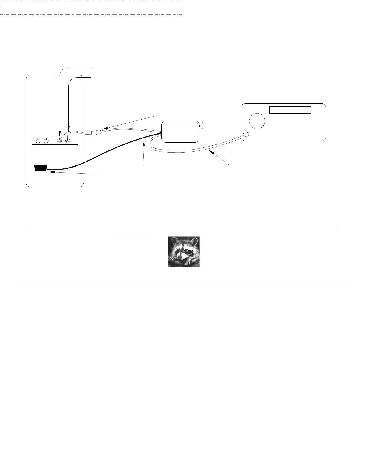
Most transceivers use the
accessory input/output jack
for PSK31, SSTV, etc. Radios
without accy I/O will use the
MIC and Ext Spkr I/O.
BucK4ABT
HF, VHF, or UHF
TRANSCEIVER
Sound Card
Transmit, Receive, & PTT
BLACK cable with
Serial Port
BucK4ABT
Some PCees are
configured different.
This illustration
is only an example.
The diagram above is only an EXAMPLE! Some PCees may have slightly different sound card I/O configuration.
female DB9 molded
connector. Attach
to PC serial comport
for automatic PTT
(TxData for RASCAL
"RY" series).
from RASCAL to
transceiver.
RASCAL ™
( RASCAL ™ = “Radio And Sound Card Audio Link” )
When we receive the RASCAL ™ ISO-KIT, we examine the parts and open the diagram. Look over the schematic and
view the pictorial of the PC board. Get an idea how the parts are arranged on the PC board (PCB). We learn the
interface that everyone has been touting as large and difficult, is not at all complicated. In fact, with our RASCAL™, it is
an easy, and straight-forward assembly that can easily be completed in a couple of hours. Soon you are on the air
operating PSK31, SSTV, MFSK, RTTY, Packet and many other fun-filled digital modes.
Don’t get in a hurry, take a few minutes to look over the drawings, illustrations, and pictorials, and become familiar with
who's on first... and 'what's on third'! I recommend using a small tip (pre-tinned preferred), pencil type soldering iron (3540 watt). If available, use a controlled heat solder station. When building the wired and tested RASCAL™, I use the
Weller WLC-100 variable heat (controlled) solder station with an ST-1 tip. Keep the tip clean, I use a small damp sponge
to clean my soldering iron tip.
THE CAVEATS!!! :
Without beating a subject to bits... and bytes, I want to drive home a simple, but important point; If you are new to
soldering, there are some rules to follow. First and foremost, DO NOT overheat wires that are shielded! When
soldering shielded wires, the center conductor may have a thin layer of insulation that can melt quickly and allow a short
to occur between the center conductor and the shield. When this happens, there will be little or no output (or input), or the
shielded cable will simply not perform the function for which it was intended. NO TECH SUPPORT FOR KITS.
Too much heat can be as damaging as not enough heat. As soon as the solder flows in the wire to wire or wire to trace,
remove the soldering iron. Be sure to use a good rosin-core solder. DO NOT use acid core solder or cleaner. As an
added assist, I use a ''LUXO'' lighted Magnifier to view the small components, and solder traces.... as something
happened to my eye-sight when I passed 65 years of age.

This ISO Kit is available from BUXCOMM.com
www.BUXCOMM.com
http://www.buxcomm.com/catalog/
AVOIDING RF FEEDBACK (SQUEALS):
While building PSK31, and SSTV, interfaces between PC sound card LINE IN, and LINE OUT, to various HF and VHF
transceivers, I've learned many valuable lessons. Some of these I'm committing to print to help you resolve problems
before they arise.
The first problem I encountered was when I had my computer too far away from my transceiver. I built the interface, and
had long leads (well over 4 feet) from the computer LINE IN, LINE OUT, and serial comport (PTT control) to the interface
printed circuit board. Then I had another 7 or 8 feet of cable from the interface printed circuit board (PCB) to the
transceiver input/output (I/O).
This is where most RF problems occur. Cables that are too long allow ingress of stray RF. In turn, it can reach the
microphone, or accessory I/O jack. This stray RF can combine with the sound card audio signal and the resulting
component becomes a “base rectified” RF feedback. When the base-rectified component reaches the transceiver audio
circuits, it creates a “squeal” in the transmitted (on air) signal.
This is why I designed the RASCAL™, using hi-quality modem type, isol ation transformers. In addition, you’ll notice in all
our RASCAL interfaces and RASCAL ISO kits, that we provide LINE IN and LINE OUT cables that have a large
ferrite core molded into the cables. These ferrite cores serve as RF chokes to prevent RF ingress into the sound card
input and output lines. You’ll find that most computers have all the sound card jacks, and serial comport connections
within a few inches of each other at the rear panel of most PCees.
Using the same strategy for the RASCAL to transceiver input/output jacks, we maintain these leads as short as
possible, or about 5 feet in length. Another RF problem can occur when the interface is placed too close to the PC
monitor (screen). Avoid close proximity between your transceiver and the PC monitor.
DC BLOCKING CAPACITORS:
In a few RASCAL BUX CommCo kits, we include a small, electrolytic or tantalytic coupling capacitor (Kits R-20, R-3, R-YX etc).
This is sometimes a 'polarized' capacitor
capacitor is between 2 uf, and 10 microfarad (uf). The voltage rating is 25 to 50 volts. The purpose of this capacitor is to
provide audio coupling and DC isolation in the microphone input. Some transceivers may supply a low bias voltage to
excite 'electret' or amplified microphones. BE SURE to install it with the 'PLUS (+) lead towards the microphone
input or the transceiver audio input. The remaining lead connects toward the (RED) isolation (PSK31 Tx audio out)
transformer lead. If the coupling capacitor has no polarity markings, then no specific pin direction or installation scheme
is necessary.
UNDERSTANDING LED and DIODE MARKINGS AND INSTALLATION:
To help you fully understand and identify the markings on the diode(s) used in the ISO-KITS, I've drawn a symbol and
picture help the user relate the symbol definition to a pictorial of a diode.
(NOTE a plus + marking near the positive lead). The value of this compact sized
SYMBOL
PICTORIAL

This ISO Kit is available from BUXCOMM.com
www.BUXCOMM.com
http://www.buxcomm.com/catalog/
The RASCAL ™ ISOlation Transformers:
All RASCAL™, and ISO kits contain isolation transformers. Look at the color of the covering around the transformer
winding. A ''RED'' tape/cover indicates a 1:1 turns ratio winding or in the case of the RASCAL™, a 600 to 600 ohms
(BUXFMR6K6) isolation transformer. In most RASCAL™, applications, a ''RED'' transformer is used in the transmit
(sound card OUT), to accessory jack, Patch In, and microphone inputs.
In many cases, the same type (color) transformer will be used in the accessory, Patch OUT, and Data Out ports. If your
RASCAL™, gets its audio from the external speaker jack (usually marked “Ext Spkr”), one of the isolation transformers
may have a 'BLUE' covering. This is a 1000 ohm to 8 ohm (BUXFMR1K8) isolation transformer. The 8 ohm side will be
wired towards the external (8 ohm) speaker jack of your transceiver, while the 1000 ohm side (marked ''P'') is wired to the
sound card, tip and sleeve (the “ring” is not used) shielded, “LINE IN,” (usually a 3.5 mm plug/jack). Please notice in the
diagram(s) that the computer sound card is isolated from the transceiver. This is our main purpose for using the "isolation
transformers." Most of my diagrams reflect the correct measures for maintaining the isolation characteristic of the
interface.
To further define... the ground/shields on the transceiver side of the isolation transformers and Opto-coupler may be
considered the PC (Digital Ground) ground, while the shield/grounds on the PC side of the 'isolation' transformers and
opto-coupler are considered (transceiver/earth grounds) the radio ground.
The transformers used in the RASCAL (BUX CommCo interfaces) will have a ''P'' printed on one side of the ''RED''
and 'BLUE' transformer winding cover(s). This ''P'' indicates the 'Primary' winding, or the first layer placed onto the
bobbin, or core. Some diagrams will note the position of the transformer in the circuit, relative to this “P” winding indicator.
NOTE; On most all isolation transformers, there are three leads on each side. The center lead from each side of the
transformer is the ''Center-Tap'' and is not used unless I specify otherwise. This center-tap may be cut off, or simply
folded back onto the winding, and taped out of the way. Insure that it does not touch any other component or any metallic
surface.
In some interface part kits, there may be a small electrolytic capacitor(s) rated at 2.2 to 10 uF. One such kit is the Yaesu
FT-847 (RASCAL™, model R-3). Another one is the RASCAL model R-20 kit that is used with many hand-held
transceivers. Notice the small print on the capacitor, and note the lead identified with a plus (+) sign. Remember that
this is the lead that goes toward the radio Data I/O connector (yep, I had to use my handy magnifier to see it, but it's
there). In these RASCAL kits, the long lead is the plus (+) lead. In other kits, the polarity doesn't matter.
In the diagrams that we provide for your RASCAL interface, we identify the I/O (accessory, Mic, Data In/Out, Patch
I/O...etc), port connector in pictorial form. This should help you identify of the connector pin-outs. I draw these diagrams
so the connector illustration depicts the solder side view
against your transceiver/radio manual. I AM NOT RESPONSIBLE FOR MISTAKES, ERRORS, OR OMMISSIONS!
of the pins. Again, a ''caveat'' PLEASE; Verify the connections
There's always that one final little 'knat-bite' that is the ''got'cha'' for many new HAMs who've never had the chance to
work with integrated circuits. I've drawn an IC (shown above) similar to the 4N33 or 4N37 that are used in many of my
RASCAL™, PSK31 interfaces. NOTE, that pin 1 is identified by a small, almost obscure circle just above the pin one (1)
location. IF the dot is not on the IC, then use the small notch to help you identify pin one (1). Hold the opto-isolator (IC)
so you are looking into the notch. Pin one (1) is the pin on the right side, nearest you. I hope my illustration will clarify pin
identification of the 4N33 and 4N37 opto-coupler/opto-isolator.
This ISO Kit is available from BUXCOMM.com
www.BUXCOMM.com
http://www.buxcomm.com/catalog/
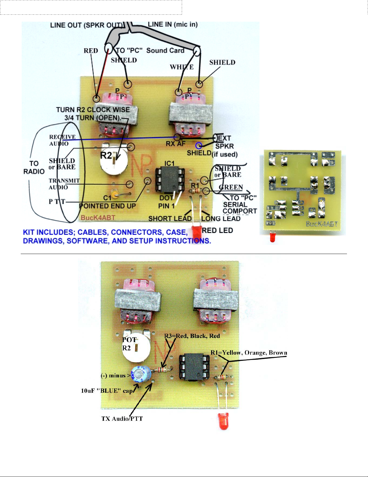
The PCB layout above, is for RASCAL kits that connect to accessory, or microphone jack.
RASCAL kits; R-3, R-20, R-HTX252, and those RASCAL kits with 2k resistor and 10 uF, blue electrolytic cap.
This PC Board is available from BUXCOMM.com at .99 cents each.
This ISO Kit is available from BUXCOMM.com
www.BUXCOMM.com
http://www.buxcomm.com/catalog/
PRINTED CIRCUIT BOARD ASSEMBLY PAGE !
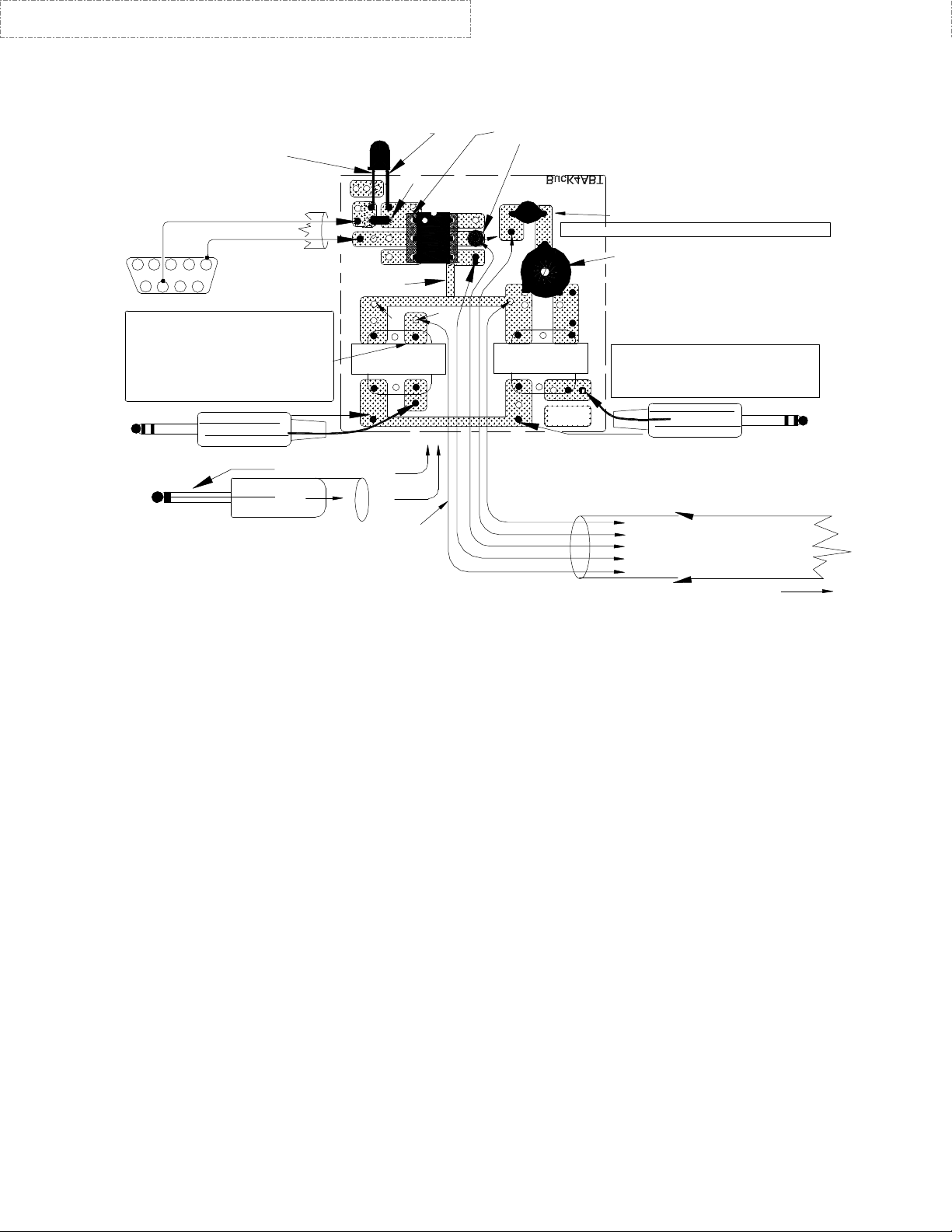
Dot or notch nearest edge of PC board, denotes pin 1 of
optoisolator = IC1 (4N33 or 4N37).
R3 is only used in RASCAL 3 and RASCAL 20
kits. R3 may be 2000 to 2700 ohms.
of R3 connects to junction of C1 and
transmit audio lead.
C1= 0.33 to 1 uf capacitor
R2
(POT)
Transmit Audio level control.
**
On some PC boards, this trace
may be missing. Add jumper/trace
using 1/4" bare wire.
Green Plug and White Plug are
joined together with a molded
ferrite RF suppressor near the
_
Soundcard end.
TIP, use RED wire
SHIELD
To Accessory Jack or MIC plug.
WHITE PLUG
Bare Wire
Transmit Audio
PTT +
PTT Receive Audio
(SHIELD/Radio Ground)
(Shield or PTT Ground)
(unless Ext Spkr is used)
"RING" not used!
WHITE PLUG
To Sound Card LINE OUT
6
5
4
NC
C1
(RASCAL MODELS R-3 and R-20, C1 = 10 uF)
T1
RED
P
N/C
Some PCees may not have sound card
input & output labeled as LINE IN & LINE OUT.
*
In this case, use MIC IN and SPKR OUT.
Free end
2
1
6
DE9 female to PC comport.
*** NOTE: When External Speaker is
used for receive audio, T2 has "BLUE"
winding covering. BLUE = 1K to 8 ohms.
When low-level, or accessory jack audio
is used, T2 has "RED" winding covering.
"RED" = 600 to 600 ohms.
GREEN PLUG
To Sound Card LINE IN
"RING" not used!
To EXT. SPKR.
Receive Audio
3.5mm External Speaker plug is used when T2 has
BLUE covering. When MIC is used for Tx AF & PTT.
T1 and T2 center-tap (center leads) not used!
SEE THE DETAILED SCHEMATIC INCLUDED WITH THIS PICTORIAL.
TOP VIEW (COMPONENT SIDE) OF PRINTED CIRCUIT BOARD. SOLDER TRACES "shown" ARE ON BOTTOM OF PC BOARD.
NOTES:
LED "Flat Side"
"Short Lead"
R1
1
2
3
NC
**
"B"
T2
***
P
TO "B"
TO "A"
"A"
GREEN wireRTS =
BARE wire
5
3 4
7
(Pin 4 = DTR)
9
8
TIP, use WHITE wire
GREEN PLUG
Red LED
"Long Lead"
SHIELD
"SLEEVE"
"TIP"
• PTT minus (-) may be same as “bare-wire” connection.
• *Reference to R3 applies only to RASCAL models R-3 and R-20. Usually a 1200 or 2200
ohm resistor. This value may vary.
• Use Sound Card software controls for Receive and Transmit “fine” settings. An on-board
transmit level control is included in the RASCAL for coarse Tx Level setup..
• For easier soldering of 13 pin DIN connectors, cut away any unused pins.
• Sound Card Plugs, LINE IN
(or, Mic IN) = GREEN, and LINE OUT (or, Spkr Out) = WHITE.
• Pin 1 is identified by a small dot on top of IC or left of notch (top view).
• “P” = Indicates “Primary” winding of transformer.
• When testing the LED Tx Indicator set up WINPSK for the correct PC serial comport.
Activate (Press) the PTT button in WINPSK for about 10 seconds, and observe the LED on
the the RASCAL. Be sure the LED is installed with the SHORT lead is toward pin 1 of the IC.
• NOTE, that some problems have been found in the Windows ME and 2000 upgrades which
sometime hold the comport RTS line “high.” This can result in the PTT being activated when
the DE9 is connected to the PC serial comport. Using “FIXCOM.EXE” may be of help to
resolve this problem. FIXCOM.EXE can be found on the internet, as a free download.

This ISO Kit is available from BUXCOMM.com
www.BUXCOMM.com
http://www.buxcomm.com/catalog/
TECH SETUP & SUPPORT:
The RASCAL™, will not work if the software and computer are not properly configured. Most problems encountered are usually due to
PC and software setup. You should always read your software documentation. The WINPSK manual is also on the disk you received
with your RASCAL™,. Be absolutely sure that you have your software set up properly before connecting the RASCAL™,. If the
software and computer are not set up and configured properly, the RASCAL will not see the correct input, output and PTT control
signal(s). It is of the utmost importance that you read the documentation that comes with your software! See the Users Manual (PDF)
file on the WINPSK disk that was sent with your RASCAL. I did not write the software and therefore, I cannot support the software.
NOTE, that some problems have been encountered using Windows ME and 2000 upgrades which sometime hold the comport RTS line
“high.” This can result in the PTT being activated when the DE9 is connected to the PC serial comport. Using “FIXCOM.EXE” may be
of help to resolve this problem.
SPEECH COMPRESSION:
Be sure all speec h compression is OFF. Observe the ALC indicator. Set the microphone gain to a level where there is little or no ALC
indication on high peaks. Always insure that it is below the maximum ALC indication.
Set the Windows volume control by double clicking the speaker icon (usually in the lower right desktop task bar), and the wave volume
as needed, to drive your radio properly. You may also adjust the transmit level with the RASCAL internal Tx ‘‘transmit level’’ control.
Or… use the Tx Level and Rx Level setup under the WINPSK “SETTINGS” Icon.
The final result of your sound card setting should be approximately mid-range or slightly higher, for the on-screen soundcard settings,
and the RASCAL™, Tx audio level control. One important item to remember; All adjustments to the soundcard will interact with other
settings of the sound card. This is the nature of the soundcard and sound card driver (software).
VOX OPERATION:
If you prefer, or if you don’t have a spare serial comport available on your PC, the RASCAL™, has transmit audio to the microphone
input when connected, setup, and software is set to “send” or “Transmit.” By having the soundcard and RASCAL transmit audio active,
you may use of the VOX circuits in your radio to activate transmit (PTT) control instead of relying on the PC serial port to control PTT
for transmit/receive. If you have only a USB port, a USB to SERIAL converter is available at “www.BUXcommCo.com for $39.95.
Set all the microphone settings as described above. Activate VOX in your transceiver, and set the level, delay and anti-trip controls
with the tones from the RASCAL/soundcard, as you would when using the microphone (voice) input. In most cases, I’ve found that
normal VOX settings perform with the RASCAL and PC as both levels are set similar.
WHEN OPERATING PSK31, SSTV, WSJT, AND OTHER SOUNDCARD DIGITAL MODES:
UNDER NO CIRCUMSTANCES SHOULD THE POWER OUTPUT OF YOUR TRANSCEIVER EXCEED ONE-HALF THE
TRANSCEIVER’S MAXIMUM RATED OUTPUT! FINAL…….. Fine Tuning, or initial receive and transmit adjustments: Let’s make
the initial adjustments to the RASCAL™ interface. We can fine-tune the Volume Control for best operation with your PSK31
program, sound card, and radio. Here are the basic things to keep in mind:
* The "Wave" slider controls the transmit level, in combination with the "Volume Control" slider.
* The Volume Control slider controls both the level going to your computer speakers, (receive or
transmit) and the overall transmit level.
* The MIC, LINE IN, or AUXILLARY controls the receive level.
Notice that running the software Volume Control slider up and down will change the level of the receive audio going to your speakers,
but it should not change the actual level of the recording (receive) stream. If you mute the input you're using to receive PSK31, the
audio will no longer be delivered to the speakers; however, it should still be sent to your PSK31 program.
SOFTWARE SETUP FOR PSK31: Using a program like “WinPSK,” enter your call sign using the “Settings” / “General Setup”
menu. Here you can enter your call and other program setup items such as the serial Comport number and PTT (RTS) settings. Your
call sign should now appear at the top of the WinPSK screen instead of the text,… ”Call Sign Not Set”. You can do the soundcard level
setup using the Tx and Rx levels shown under the “Settings” menu. Use the built in wave file player and recorder to get familiar with
your sound card’s mixer settings and capability. The mixer control is used to set both the receive audio level to the PSK program as
well as set the “coarse” level setting to your transmitter. If you are using the MIC input, you should use the radio’s mic gain for precise
level adjustments.. It is also a very good idea to disable all the various Windows sounds if you have only one sound card, especially if
you are using VOX PTT control.
FYI, a good frequency to begin operating PSK31 is at: 20 mtrs @ 14.070 MHz USB
73 es I hope to QSO w/U on PSK31 soon, de Buck Rogers K4ABT@BUXcommco.com
For Antennas, Accessories, Connectors, and Electronic Components, VISIT; www.BUXcommCO.com
This ISO Kit is available from BUXCOMM.com
http://www.buxcomm.com/catalog/
www.BUXCOMM.com
PRELIMINARY SETUP FOR WINPSK SOFTWARE AND THE RASCAL®™
Sound Card to Radio Interface:
Most soundcards that work under Windows should work okay with WinPSK. It needs to be a 16 bit type
with preferably a "line IN" jack and perhaps a "line OUT" jack as well. The 16 bits refers to the audio
resolution and NOT the PC bus type which can be ISA, PCI, USB, etc. as long as it is supported by
Windows. The most expensive sound card is not always the best in terms of audio quality. Many $10
soundcards have better audio specs than the expensive "do everything" soundcards.
First lets look at the radio receive audio to soundcard connection. Most radios have an Ext Spkr jack on
the back. If your sound card has a "line IN" jack all that is needed to run the GREEN plug, shielded cable
from the RASCAL audio out to the line IN jack on the soundcard. If the soundcard only has a "MIC"
input then you may have to attenuate the signal with a simple 2 resistor divider. Connect the white plug
from the RASCAL to the sound card LINE OUT (or SPKR OUT).
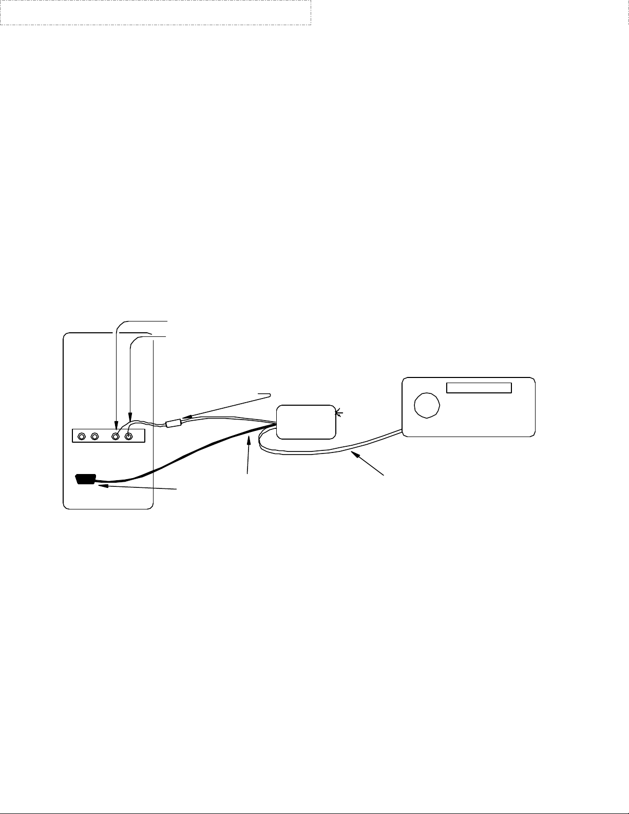
The audio jacks on soundcards are the 3.5mm (1/8”) type. WinPSK operates in the monophonic, single
channel mode so a mono connection can be used. A typical cable wiring scheme is shown here. This is
only a starting point.
WHITE PLUG = LINE OUT
GREEN PLUG=LINE IN
PC
WHITE cable with
molded ferrite
RF suppressor.
HF, VHF, or UHF
RASCAL
BucK4ABT
Sound Card
BLACK cable with
Serial Port
BucK4ABT
Some PCees may have MIC IN and SPKR OUT, instead of LINE IN and LINE OUT.
Program Setup
Before going on the air, you should enter your call sign using the "Settings" Icon, then "General Setup"
menu. Here you can enter your call and some other program setup items such as the COM port PTT
settings. Your call sign should now appear at the top of the WinPSK screen instead of the text "Call Sign
Not Set"
DE9, 9 pin molded
connector. Attach
to PC serial comport
for automatic PTT
(TxData for RASCAL
"RY" series).
TRANSCEIVER
BucK4ABT
Transmit, Receive, & PTT
from RASCAL to transceiver.

This ISO Kit is available from BUXCOMM.com
http://www.buxcomm.com/catalog/
www.BUXCOMM.com
Most of the settings including last used TX and RX frequencies, display settings, etc. are saved into
Window's registry upon program exit,.

This ISO Kit is available from BUXCOMM.com
http://www.buxcomm.com/catalog/
It's a good idea to make sure your sound card is installed properly and is working correctly before tackling
the WinPSK soundcard level setup. Use the built in wave file player and recorder to get familiar with
your sound card's mixer settings and capability. It can be activated from within WinSPK by going to the
"Settings" menu and clicking on either the Rx or Tx Level adjust item. (If you are using NT or Win95,
you will have to manually select the record option in the mixer control to set the receive volume) The
mixer control is used to set both the receive audio level to the WinPSK program as well as set the
"course" level setting to your transmitter. One should use their radio's mic gain for fine adjustments. The
RECORDER mixer settings are used to control the receive audio level while the PLAYBACK mixer
settings are used to set the transmitter audio level.
Receive Audio Input Level
Once the interface is connected, the first thing to do is set your receive audio level. Tune your radio to a
loud signal or carrier. Bring up your soundcard's Mixer program (or use the one that comes with
Windows). The Mixer's RECORDER settings are the ones to use for adjusting the Receive audio levels.
Select either the LINE or MIC IN control and set it mid way.
Click on the WinPSK Signal Display TAB labeled "Input". Adjust your recording Mixer controls for a
signal display that is about half screen size on peaks. If the level is too high, the signal display will turn
red. Here are some example settings:
www.BUXCOMM.com
If in one of the spectral signal views, a red message will warn of too high audio.
You should now be able to start receiving PSK31 signals from off the air. Use one of the spectrum signal
displays and just left-click the mouse cursor close to a signal peak that looks like a PSK31 signal. Make
sure the AFC is checked and the correct PSK31 mode (probably BPSK) is selected. Click on the bottom
part of the squelch control until it turns ye llow. This will "open" the squelch if it is set too high. Text
should appear in the RX text window.
Transmit Audio Level Adjustment
This is probably the trickiest part of PSK31 setup because one cannot see the actual signal spectrum
coming out of their transmitter.
This ISO Kit is available from BUXCOMM.com
http://www.buxcomm.com/catalog/
In the initial setup, you must guess at a good level then get someone to give you a critical signal report
over the air. The Mixer's PLAYBACK settings are the ones to use for adjusting transmit audio levels.
Compounding the problem is the fact that the soundcard is producing around 1 volt of audio and the
typical transmitter Microphone input needs only a few millivolts to drive it. One must be very careful to
attenuate the soundcard signal by about 1/1000 before attempting to drive the microphone input. Here is
where the RASCALs internal Tx audio level control come into play.
If you are unable to lower the transmit level low enough by using the sound card Tx Level settings, then
you may use the coarse (manual) Tx audio level control inside the RASCAL engine. As a rule, this pot is
factory set to mid range.
A good rule of thumb is to not have any level control near it's extreme. The mixer control should not be
at it's maximum or minimum and your radio MIC gain should not be at either extreme.
The correct setting will vary from radio to radio. In general, one should not drive the transmitter
anywhere near it's rated power at least not at first. If you must error, error on under driving your rig until
you are comfortable that your signal is clean then try bumping it up and see where your signal starts
"getting wide" as observed by the receiving station.
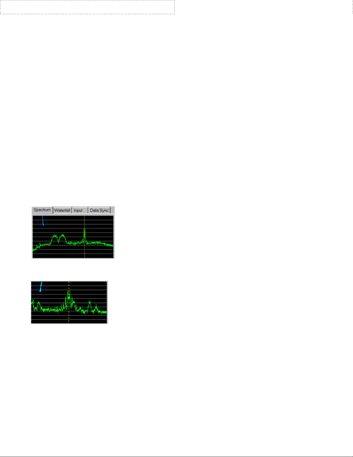
The following graphic is an example of a good strong PSK signal. he noticeable sidebands are down in
amplitude.
www.BUXCOMM.com
In the example below, a PSK31 signal that is "Too Wide", is probably the result of being overdriven.
There are sidebands only about 15 dB down and the signal is interfering with another PSK31 station just
above it in frequency.
Study the MACRO settings, and more detailed information in the WINPSK PDF file/manual on the disk
you received with your ISO kit.
Have fun with PSK, es 73 de BucK4ABT VISIT: www.PacketRadio.com

Dashed Lines = PC Board
hSh
a
This ISO Kit is available from BUXCOMM.com
http://www.buxcomm.com/catalog/
(GREEN WIRE)
(RTS)
(BARE)
If "DTR" line is to be
the PTT driver, then
use pin 4 (RED wire).
Sound Card "LINE IN"
TIP
BucK4ABT
(GREEN PLUG)
"WHITE WIRE"
Shield
"RING" Not used!
Sound Card "LINE OUT"
TIP
BucK4ABT
(WHITE Plug)
"RED WIRE"
Shield
"RING" Not used!
Long Lead
(R1)
D1
1N4148/1N914
R2
Red
LED
LED1
R3
n/c
OPTOISOLATOR
"P"
DO NOT CONNECT
TOGETHER !
n/c
"P"
BucK4ABT
T1
T2
n/c
PTT
Gnd/Shld
(J1)
n/cn/c
Gnd/Shld
_
+
C1
n/c
Gnd/Shld
Rx Audio
Tx Audio
www.BUXCOMM.com
(3
* Note th
S
ISO kit for PSK31, No tech support for kits built by others.
R1 = 750 ohms Violet, Green, Brown or 1000 ohms (Brown, Black, Red)
R2 = 1,000 Ohms (Brown, Black, RED
R3 = Potentiometer (1 k POT) for transmit audio (coarse
(Use Sound Card software control for Receive and Transmit “fine” level
settings.)
C1 = Capacitor, 2.2 uf. Or similar (1 to 8 uf)
D1 = Diode, 1N914 or
1N4148
LED = Red, LED; Note position of “LED long lead.”
)
) level control.
T1 = “RED” winding color (600 to 600 ohm) color. Center tap may be used for (B)
“RED” winding color (600 to 600 ohm) color.
T2 =
IC 1 = Optocoupler (photo-transistor) PTT Isolator.
J1 = 1-¼ inch, insulated wire added between ground
NOTES:
und Card Plugs, LINE IN = GREEN, and LINE OUT = WHITE.
• So
trace and IC pin 4.
• “P” = Indicates “Primary” winding of transformer.
• Optoisolator pin one (1) is identified by a small dot on top of IC.
 Loading...