

Page 1
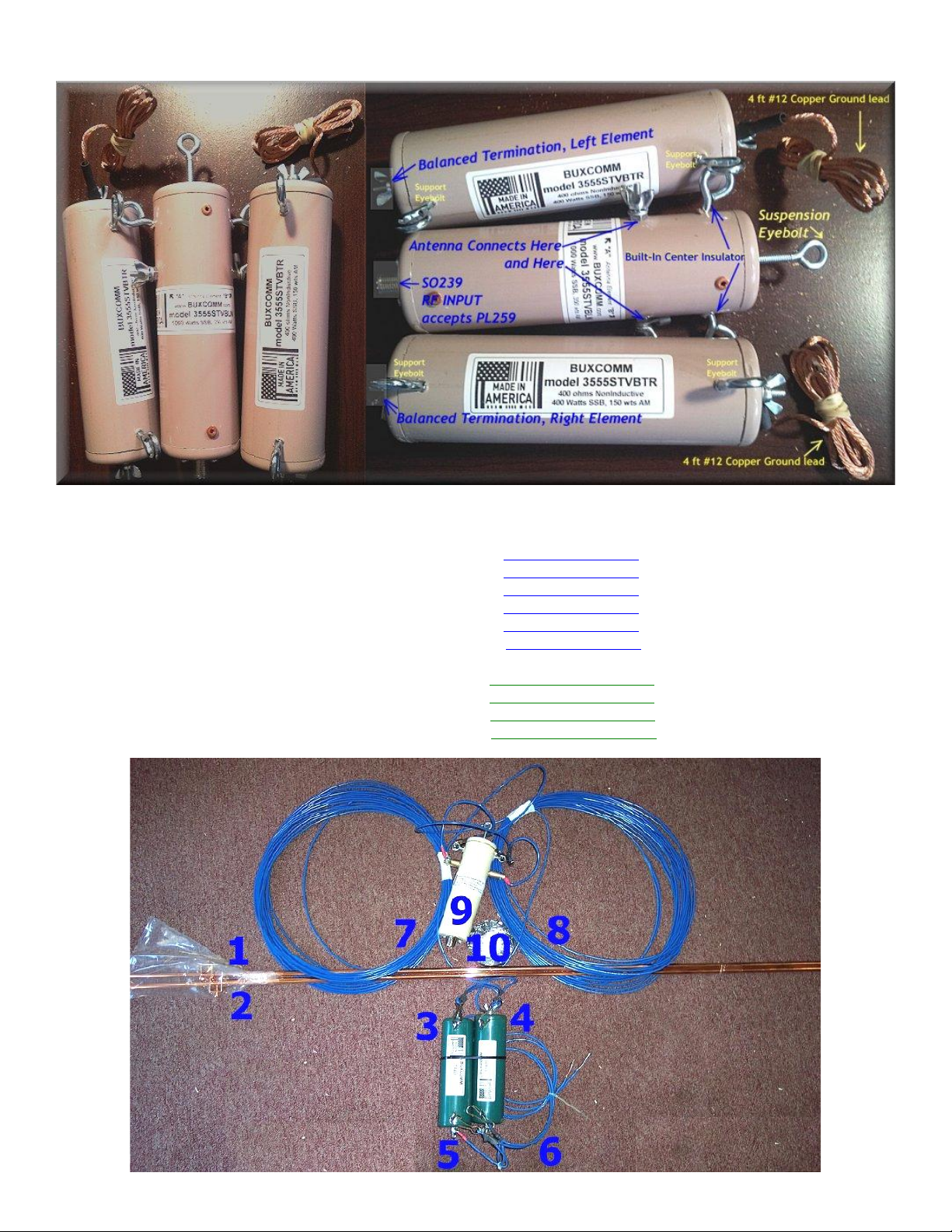
BUXCOMM 3555-STV Kit, Sloping Terminated Vee Antenna Assembly and Installation
Items shown above are included in the BUXCOMM 3555STV kit
Parts and Components, see photo below:
3) 400 ohm, non-inductive, Balanced Termination INCLUDED with Kit
4) 400 ohm, non-inductive, Balanced Termination INCLUDED with Kit
5) Ground leads from BTR to left ground-rod. INCLUDED with Kit
6) Ground leads from BTR to right ground-rod. INCLUDED with Kit
9) 1:16 BALUN (50 to 800 ohm) INCLUDED with Kit
10) Assembly and Installation guide. INCLUDED with Kit
1) Copper Clad Steel Ground-Rod with clamp. CUSTOMER SUPPLIED
2) Copper Clad Steel Ground-Rod with clamp. CUSTOMER SUPPLIED
7) 96 ft AWG 14 copper wire (left element). CUSTOMER SUPPLIED
8) 96 ft AWG 14 copper wire (right element). CUSTOMER SUPPLIED
Page 2
The ideal antenna for restricted communities, small lots, MARS, commercial, military, and portable operation. With
High Gain on all HF frequencies in excess of 5dB over a dipole. Use the illustrations on the following pages as an
installation guide. Once the antenna is installed, there is no additional tuning or cutting. Connect your coax cable and
enjoy.
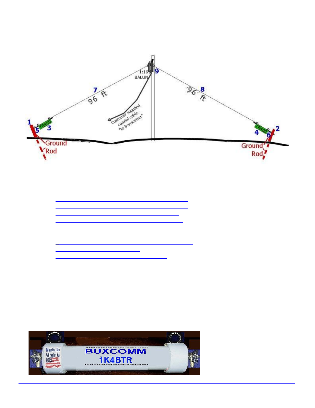
Items: 3, 4, 5, 6, 9,and 10 are included with the BUXCOMM 3555-STV Kit
Items: 1, 2, 7, and 8 are supplied by customer
1) Copper Clad Steel Ground-Rod with clamp.
2) Copper Clad Steel Ground-Rod with clamp.
3) 400 ohm, non-inductive, Balanced Termination
4) 400 ohm, non-inductive, Balanced Termination
5) Ground leads from BTR to left ground-rod.
6) Ground leads from BTR to right ground-rod.
7) 96 ft AWG 14 copper wire (left element).
8) 96 ft AWG 14 copper wire (right element).
9) 1:16 BALUN (50 to 800 ohm) with built-in center
insulator and center support.
10 Assembly and Installation Instructions
Do not use Solid Wire. Do not install near power lines, limbs, metal, or vegetation! Never work alone.
As-built, the 3555STV operates well from 1 mHz to 55 mhz. Where enough real-estate for the BUXCOMM
3555STV Kit, is limited, the elements can be pruned to 48 feet on each leg. This reduction in length sacrifices
some of the antenna’s gain and bandwidth. This shorter version operates well from 3.5 to 30 mHz. No other
changes are required when making this modification. If you wish to be more precise, then use the formula;
220/F= length in feet. As example, if we want a VeeBeam to have a band width extending from 3.8 mHz (75
mtrs to 10 mtrs), we use the lowest frequency of operation to calculate the length of one side (element) of our
Terminated Vee Beam, Thus; L=220 / 3.8 = 57.9 feet.
As built, the BTR400 are rated at 400
watts SSB, The BALUN is PoweRated
at 1000 watts SSB, or 400 wts AM. An
upgrade kit is available as cat#
1K4BTR (a pair is required). (A new
BALUN is not required.)
They can be ordered at:
http://www.packetradio.com/catalog/index.php?main_page=product_info&cPath=36&products_id=2700
Page 3
3555-STV kit Specifications: (when installed according to this manual)
Input power rating: 400 watts SSB, 150 watts RMS, AM, FSK (RTTY) or PSK.
Feed point impedance: 50 ohms nominal
Feed point VSWR: Better (less) than 2:1 typical 3.5-35 MHz, 2.5:1 35-55 MHz.
BALUN impedances:
50 ohms in to SO239 connector. BALUN accepts PL259.
Antenna feed point, 800 ohms, fed with BUXCOMM B15C161, 16:1 BALUN
BTR X 2, are 400 ohms Termination Resistors
In addition to good gain/bandwidth characteristics, the BUXCOMM 3555STV Kit is easy to build
and install and works great on the HF frequencies.
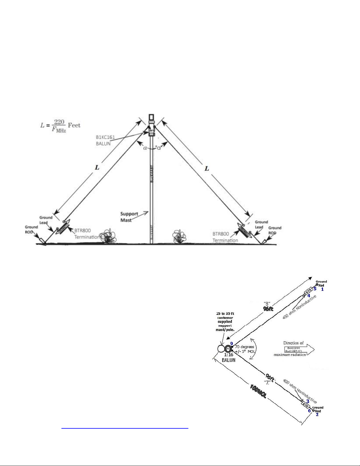
The vee- beam
can be viewed as
an inverted dipole
antenna fed in the
center like a
dipole. By the
definition, the
sloping,
terminated, veebeam, has a
similarity to the
dipole. The
center is elevated
as high as
possible from
ground surface,
however, the ends
slope to close to
the surface. Angle
“a” can be almost
anything, provided
that “a”is greater than 70 degrees; typically, most terminated vee beam antennas use an angle of about 120 degrees.
Broadband Sloping Terminated Vee Beam
antenna profile(s):
This is a slope terminated traveling wave Vee Beam antenna, which
has a constant current distribution along its length. The drawings
show the placement of the balanced termination resistors at the far
end of each element.
Vee beams like the single-wire antennas, can be made non -resonant
by terminating each wire in a resistance that is equal to the
antenna’s characteristic impedance. Although the regular vee is a
standard wave antenna, the terminated version is a traveling wave
antenna and is unidirectional. Traveling wave antennas are
unidirectional because the terminating resistor absorbs the incident
wave after it has propagated to the end of the wire. In a standingwave antenna, that energy is reflected backwards toward the source,
so it can radiate oppositely from the incident wave.” We hope you
enjoy this antenna as much as we do, and may you have many DX
contacts;
73 de BucK4ABT
Visit: http://www.buxcomm.com/catalog
 Loading...