

Page 1
Page 2
Page 3

REVISION HISTORY
TABLE OF CONTENTS
Revision
A
This device complies with Part 15 of the FCC Rules. Operation is subject
to the following two conditions:
interference, and
including interference that may cause undesired operations.
Change Activity
Release
this device may not cause harmful
this device must accept any interference received,
Date
01 I29193
C OPYRIGHT
Copyright 1993 BusLogic Inc. All rights reserved.
Inc. makes no warranty of any kind with regard to this material,
including, but not limited to, the implied warranties of merchantability
and fitness for a particular purpose.
contained herein or incidental or consequential damages in connection
with furnishing, performance or use of this material.
This document contains proprietary information which is protected by
copyright. All rights are reserved. No part of this document may be
photocopied, reproduced or translated to another language without prior
written consent of
Inc.
is not liable for any errors
TRADEMARKS
Company and product names are trademarks or registered trademarks of
their respective companies.
Section 1: introduction
VL-Bus
SCSI Peripherals
ASIC
Technology ...................................................................... 1-l
Unique Features
Benefit
Product Overview ............................................................................ l-4
Host
SCSI Interface
Microprocessor .......................................................................... l-5
Multitasking Operation.. .........................................................
DOS
Specifications .................................................................................... l-6
Reference Documents ...................................................................... l-6
Hardware
Hardware ................................................................................... l-7
Software.. ................................................................................... .1-7
......................................................................................... l-2
Interface
Controller ..................................................................... l-5
Support.. ............................................................................ l-5
and
........................................................................ l-l
....................................................................... .1-2
............................................................................ l-4
............................................................................ l-5
Software Requirements ........................................ l-7
Section 2: Unpacking and Installation
Unpacking and
Installation Tools
Configuration Instructions
Host Adapter
SCSI Parity
Disk
Adapter Initiate Synchronous Negotiation
Maximum Synchronous Data Rate Allowed
VL-Bus
Host
Inspection
.............................................................................
SCSI ID
................................................................................
Drive Capacity
Clock
Speed
I/O
Port Address..
.............................................................
............................................................
...........................................
.............................................................
................................................................
..........................
.......................
................................................................
..........................................................
.2-2
.2-2
.2-3
.2-3
.2-4
.2-4
.2-5
.2-6
.2-6
Page 4
T ABL E OF C ONTENTS, CONTINUED
Host
Host Interrupt Request
Floppy Subsystem
Summary of the BT-445s Switch and Jumper Settings..
Installing the BT-445s
Host Adapter Integration
Device Termination
Cabling
SCSI Device ID Selection.
Hard
Disk
Set-up, Initialization, and Partitioning Procedure
Warranty Information
(16K Bytes)
Requirements
Initialization
Address
.............................................................
.....................................................................
...................................................................
..............................................................
...........................................................
...............................................................
..................................................................
.............................................
Appendix A: Internal Diagnostics
List of Figures
l-l. The BT-445s Block Diagram
l-2.
The
2-l. SCSI Terminator Configurations
.................................................... l-2
.......................................... l-4
.........................................
List of Tables
l-l. Specifications
2-l.
The Host Adapter SCSI
2-2. The VL-Bus Clock Speed
2-3.
The Host I/O Port Address..
2-4. The
2-5. The
Host Interrupt Request
2-6. The
2-7.
Summary of the
2-8. Summary of the
.............................................................................
ID Setting
........................................
..................................................
Host BIOS Address
............................................
....................................................
Jumpers
.................................................
Switch Settings..
Jumper Settings
.........................
..........................
..........
............
.2-7
2-8
2-9
.2-13
2-16
2-16
.2-17
2-17
.2-18
.2-18
.2-22
.2-16
l-6
.2-3
2-6
.2-7
2-8
.2-8
2-9
.2-10
2-12
n
32-bit bus master DMA data transfers of up to 40
n
Built-in drivers for
available for
n
Scatter-gather data transfers that permit non-contiguous memory
and
and DOS
as well as optional drivers
storage and retrieval
SCSI Peripherals
Up to 10 MBytes/set synchronous and up to 7 MBytes/set asynchronous SCSI data transfers
Support of the single-ended SCSI interface with active termination
SCSI-2 command set compatibility
Both an internal and an external
connector for the external connector)
Wide range of SCSI hard drives, and other SCSI peripherals sup-
ported
Technology
SCSI connector (SCSI-2
Bus master ASIC designed by
High-performance advanced SCSI controller
microprocessor that reduces the host’s CPU overhead
Floppy controller chip for any combination of up to two 3.5” or
5.25” drives
Reduced component count that yields greater reliability
Introduction
1-i
Page 5
VL-Bus
DMA
Bus Master
SCSI Interface
Controller
Peripherals
ADVANTAGES, CONTINUED
Unique Features Benefit
PC/AT Host
System Bus
Figure l-1. The
ADVANTAGES
Unique Features
BusLogic-designed universal
bus master ASIC provides the
highest level of integration in
the industry
Disk
Block Diagram
Benefit
Exceptionally high product
reliability due to reduced
component count and lower
power consumption
Fast single-ended SCSI support with active termination
Small form factor
Complete device driver
support for all the popular
operating systems: DOS,
UNIX, XENIX, NetWare,
etc.
Higher SCSI data transfer rate
and higher data reliability.
Allows flexible system integration with complete driver/
software transparency
n
Easier system integration
n
Provides turn-key solution for
system integration
ASIC allows common architecture for a family
of SCSI host adapter products
across the popular industry
standard buses: ISA, EISA,
Micro
and VL-Bus
High-speed,
on-board microprocessor
1-2
Installation
Guide
Allows easy feature enhancements and device driver support
for all industry standard buses
Higher performance due to
minimized command overhead
and faster command execution
introduction I 1-3
Page 6
PRODUCT OVERVIEW
SCSI Interface
The
master host adapter product based on a BusLogic-designed, universal ASIC
technology. It provides a high-performance interconnection between the
Video Electronics Standards Association’s
and Small Computer System Interface (SCSI) peripheral devices. It is designed for multitasking operating systems such as UNIX, XENIX, NetWare,
as well as DOS. UNIX and XENIX both contain built-in driver sup-
port for the
also available as optional items.
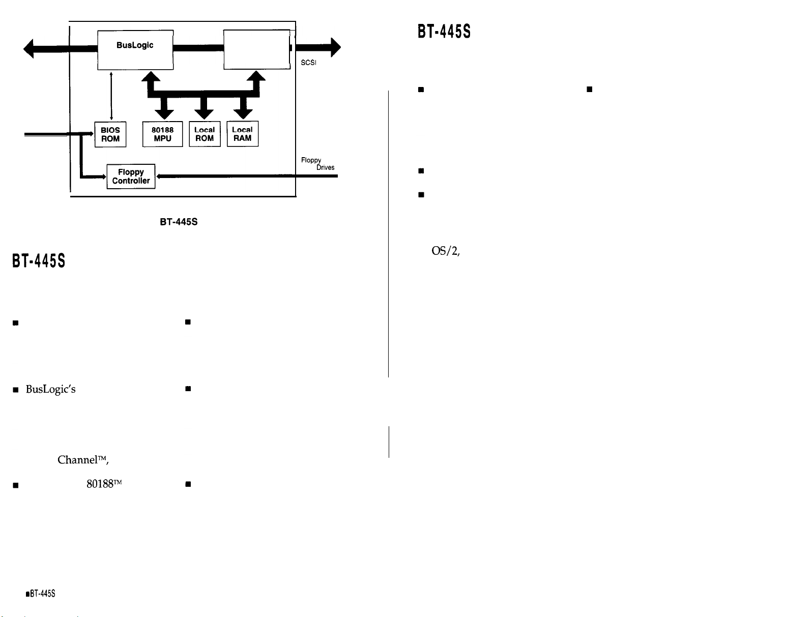
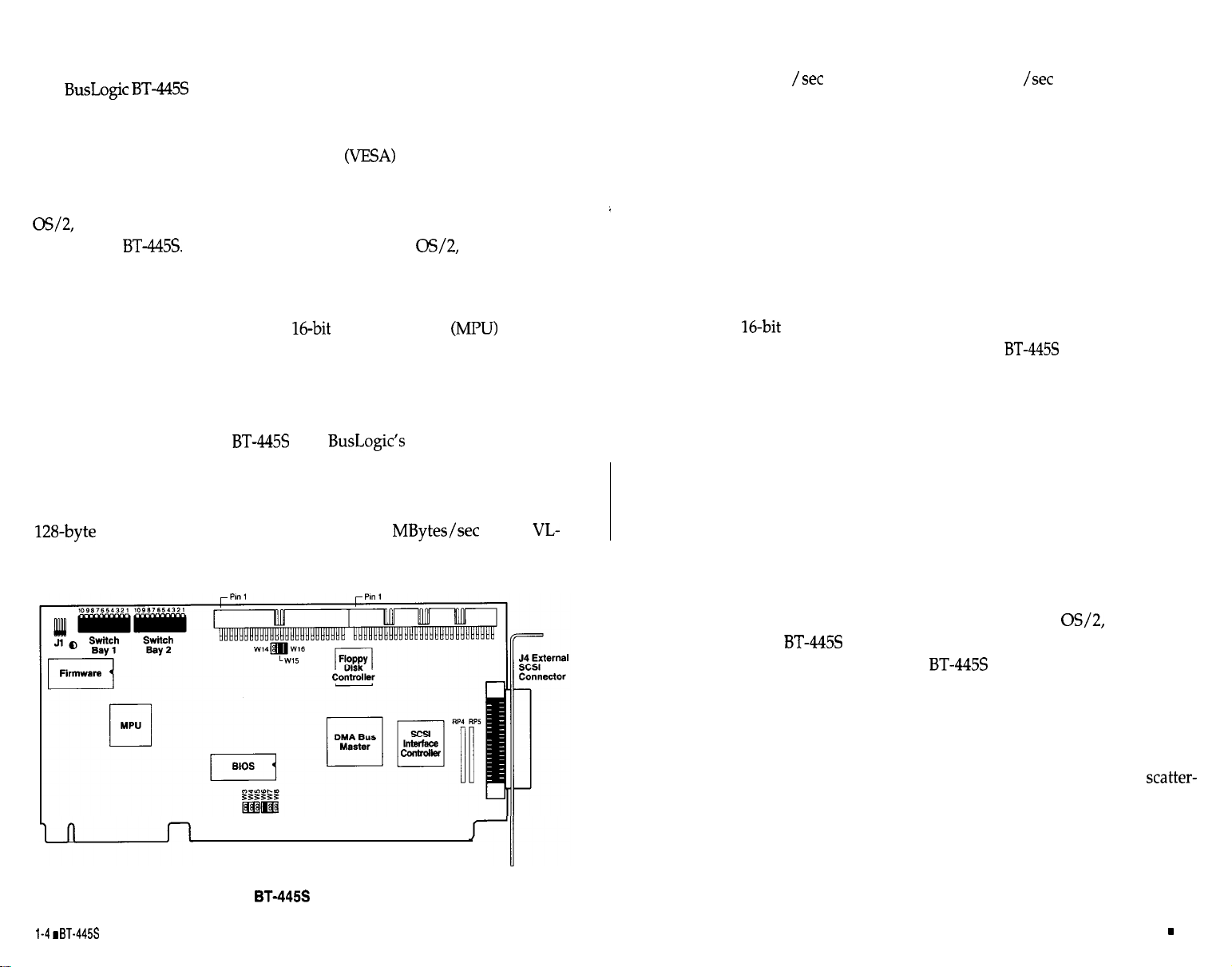
As Figure l-l indicates, the BusLogic-designed bus master controller ASIC,
the SCSI interface controller, and a
higher speed, lower power consumption, fewer parts, and higher reliability.
host adapter is an intelligent VL-Bus to SCSI bus
local bus, the VL-Bus,
Software drivers for NetWare,
microprocessor
and DOS are
provide
Host Interface
As Figure l-2 indicates, the
ter interface chip to provide VL-Bus bus master DMA operation. Bus
master DMA reduces the number of interrupts generated per I/O command thus enhancing system performance. This interface chip contains a
FIFO to burst 32-bit wide data up to 40
Bus. Selectable interrupt and I/O address ranges are available.
uses
high-speed bus mas-
on the
Up to 10 MBytes synchronous and 7 MBytes /set asynchronous SCSI
data transfers are supported by the SCSI interface controller. This chip
reduces protocol overhead by performing common SCSI algorithms or
sequences in response to any single SCSI-2 host command. SCSI-2 interface specifications for termination power and fusing (with blown-fuse
indication) are implemented. The board has both an internal and an
external 50-pin connector for flexibility in attaching SCSI devices to the
system.
Microprocessor
An 80188
head. This MPU coordinates all activity
of the board’s firmware, including initialization, command decoding,
interrupt generation, and control of the data flow among the board’s components.
MPU is used to supply the speed for low command over-
on
the
under the direction
Floppy Controller
The floppy disk controller is fully IBM register set compatible. All combinations of up to two 3.5” and/or 5.25” devices are supported.
BT-445s
Figure 1-2. The
Installation
Guide
J2 Floppy Disk Connector
n
Host Adapter Board
J3 internal SCSI Connector
Multitasking Operation
For operating systems such as UNIX, NetWare, and
protocol of the
the use of a mailbox structure, the BT-445s can support up to 255 tasks
with minimum host processor intervention. On-board firmware controls
all of the SCSI activity that a task requires, including the Arbitration,
Selection, Disconnection, Reconnection, and command completion status. This same mailbox protocol supports both initiator and target mode
operation permitting high speed host-to-host communication and
gather data transfers.
provides true multitasking operation. Through
the mailbox
Introduction
1-5
Page 7
support
An on-board ROM BIOS enables single-tasking DOS operation; however,
bus master DMA is still used to improve the data transfer performance. A
storage capacity of up to 8
per disk is supported by the BIOS.
n
IBM’s PC/AT technical reference manual (optional)
n
Installation guide for
device drivers (if required).
HARDWARE AND SOFTWARE REQUIREMENTS
SPECIFICATIONS
Refer
to
Table l-l for a summary of the physical and electrical specifica-
tions.
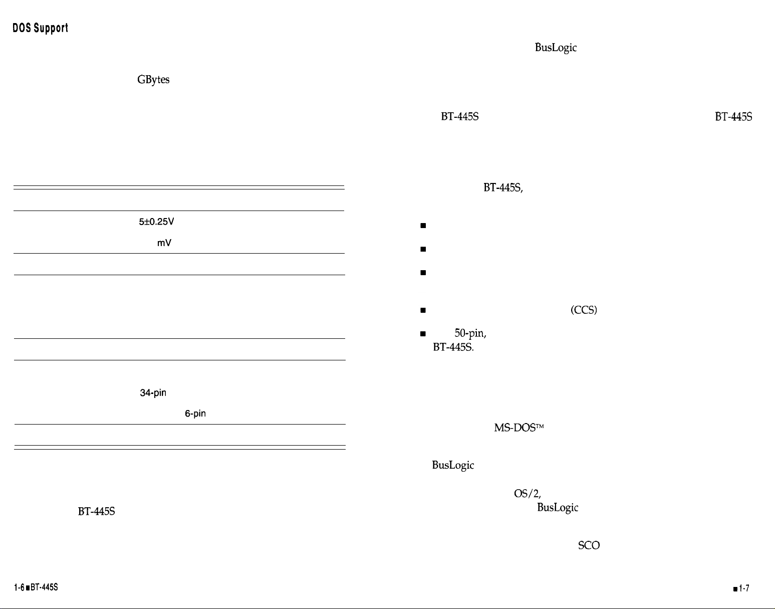
Table l-l. Specifications
Electrical
Operating
Operating Current
Max. Ripple/Noise
Environmental
Temperature
Relative Humidity
Altitude
Dimensions
Interface Connections
SCSI Internal
SCSI External
Floppy Internal
To/From System
MTBF
Voltage
1 .OA
100
0°C to 60°C
10% to 95% non-condensing
0 to 10,000 ft. operating
0 to 15,000 ft. non-operating
9.6” x 4.8
50-pin double-row connector
50-pin shielded SCSI-2 connector
IBM PC/AT standard 36-pin, 62-pin and the
VL-Bus 11 g-pin edge connectors
90,000 hours
The BT-445s can be installed in a VL-Bus system. To install the BT-445s
successfully, you must have the following hardware and software.
Hardware
To install the
ing hardware:
One or more 3.5” or 5.25” floppy drives
One available VL-Bus slot
DC power for an internal 3.5” or 5.25” SCSI drive or an external
subsystem with the corresponding SCSI-2,50-pin external cable
One Common Command Set
One
flat ribbon cable to connect internal SCSI devices to the
you must have a VL-Bus system with the follow-
SCSI-2 compatible device
Software
For installation in a DOS environment, you will need:
n
PC-DOS” or
programs
with the SETUP, FDISK, and FORMAT
REFERENCE DOCUMENTS
To install the BT-445s in a VL-Bus system, you should have the following documentation:
n
VL-Bus system installation and set-up guide
n
Operating system installation and user’s guide
Installation Guide
n
For installation in an
will need the appropriate
DOS SCSI Software Manager (if required).
Novell NetWare 286 or 386 environment, you
device driver for your operating sys-
tem.
Drivers for INTERACTIVE UNIX,
with the operating system.
UNIX, and XENIX are included
Introduction
Page 8
Page 9
n
Small screwdriver
Host Adapter SCSI ID
n
Small needle-nosed pliers.
CONFIGURATION INSTRUCTIONS
The
actions:
Setting on-board switches and jumpers
Configuring SCSI devices
Verifying that the terminators are installed correctly
Placing the
Cabling the on-board connector to a SCSI target.
The
jumpers and switches in the switch bays. The
and jumpers will need to be changed if conflicting port assignments or
memory allocation is encountered. The locations of these switches and
jumpers for the BT-445s are shown in Figure l-2.
The default settings for switches and jumpers for the
from the factory are listed in Tables 2-1 through 2-6. For a summary of these
switches and jumpers, refer to Table 2-7 and 2-8.
Before installing the
settings and jumpers have been set according to the target system’s operating requirements.
must be configured for use by performing the following
board into the VL-Bus slot and
operates with most VL-Bus systems with the factory set
switch bay settings
as shipped
host adapter board, verify that the switch
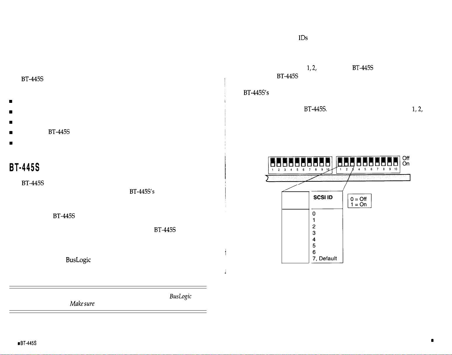
There are eight SCSI
(O-7) on a SCSI bus. SCSI ID 7 has the highest priority. Each initiator or target on a SCSI bus must be assigned a unique
SCSI ID.
Switch Bay l’s Switches
Because the
is an initiator on the SCSI bus dispatching host com-
and 3 set the BT-445s SCSI address (in binary).
mands to all SCSI targets on the bus, the default SCSI ID is 7. Note that the
on-board BIOS requires that your SCSI drives be configured for
SCSI ID 0 and 1. This requirement is important only if you intend to boot
your system from the
and the resulting SCSI ID are provided in Table 2-l.
Complete settings of Switches
The as-shipped (default)
and 3,
SCSI ID is 7.
Table 2-1. The Host Adapter SCSI ID Setting
Switch Bay 2
Switch
123
000
100
010
1 10
001
101
011
1 1 1
Switch Bay 1
SCSI Parity
Warning: Change
the switches and jumpers before installing the
board
info the VL-Bus sysfem. Makesure fhaf you areproperlygrounded beforedoingso.
2-2
Installation Guide
There are 8 bits of data plus one bit of parity on a standard SCSI bus. Switch
Bay l’s Switch 4 lets you enable or disable parity on the SCSI bus. By
default,
Switch 4 is ON, enabling parity.
Unpacking and Installation
2-3
Page 10

Disk Drive Capacity
DOS Disk Space
on-board BIOS is enabled to service interrupt
the BIOS intercepts host interrupt
the
to access the SCSI devices. If the overall DOS disk space is to
exceed 1 GBytes, this option has to be enabled. When this option is enabled,
the BT-445s BIOS allows DOS to access up to 8 GBytes per disk. Otherwise,
DOS can only access the first 1 GBytes even if the formatted disk capacity
is greater than 1 GBytes.
For most operating systems other than DOS, for example, NetWare, UNIX,
and
the 1 GByte limitation exists only during the boot process when
interrupt 13H is used. Once booted, these operating systems can access the
entire disk space without the 1 GByte limitation.
1 GBytes.
In the DOS environment, when the
for SCSI disk accesses,
calls and dispatches commands to
the
By default Switch 6 is
ON
which disables synchronous negotiation
initiation by the BT-445s.
This default mode assumes that a SCSI target device connected to the
that they initiate the synchronous negotiation. Such devices may fail to
respond to commands from the
if a synchronous negotiation
occurs unexpectedly. Conversely, other target devices may expect an initiator to begin the synchronous negotiation sequence. If this class of SCSI
target devices is connected to the
Switch 6 may set to
OFF
to allow
the host adapter board to initiate the negotiation for a synchronous data
transfer with a selected SCSI target device.
Maximum Synchronous Data Rate Allowed
Therefore it is recommended that this option be enabled only if greater than
1 GBytes of disk space is needed under DOS. For all other operating systems, as long as the bootable image resides below the 1 GByte range, this
option can be disabled without losing the accessibility of the entire drive.
Switch Bay l’s Switch 5 is used to enable or disable this
support. To enable >l GByte DOS support, set Switch 5 to
Switch 5 is ON which disables the
1 GByte support.
1 GByte DOS
(OFF). By default
Note: Before thisoption ischanged,you must backup fheentirediskimageon fhose
drives that havegreater than 1
must then reformat all thosegreater than 1 GByte drives and
of capacity. After the option is changed,
all thefiles.
you
Adapter Initiate Synchronous Negotiation
The SCSI protocol allows synchronous negotiation to determine the
ACK offset and the data transfer rate for synchronous transfers between an
initiator and a target on the SCSI bus. The actual data transfer rate is determined by the lower of the rates between the initiator and the target.
Because the
the actual data transfer rate is determined by the SCSI drive if the drive has
a data transfer rate lower than or equal to 10 MBytes/set. Switch Bay l’s
Switch 6 is used to enable or disable synchronous negotiation initiation by
is capable of up to 10
SCSI data transfers,
The SCSI controller chip on the BT-445s has the capability of supporting
SCSI data rates of up to 10
Switch Bay l’s Switch 7 determines the maximum SCSI data transfer rates.
The default setting is
OFF,
it allows you to transfer data up to 10
ON
which supports up to 5
If Switch 7 is
Note the following two points: (1) in order to achieve a 10 MBytes/set transfer rate, this option and the Adapter Initiate Synchronous Negotiation
option must both be enabled, and (2) some older SCSI drives that can only
support a data rate of up to 5
during the negotiation that it can transfer data above 5
the
is connected to such drives, the 5
used. Otherwise, it will cause data transfer failure. The
may misinform the
option must be
default
When
is the
5
option.
2-4
BT-44%
Installation
Guide
Unpacking and Installation
2-5
Page 11
VL-Bus Clock Speed
Table 2-3. The Host
Port Address
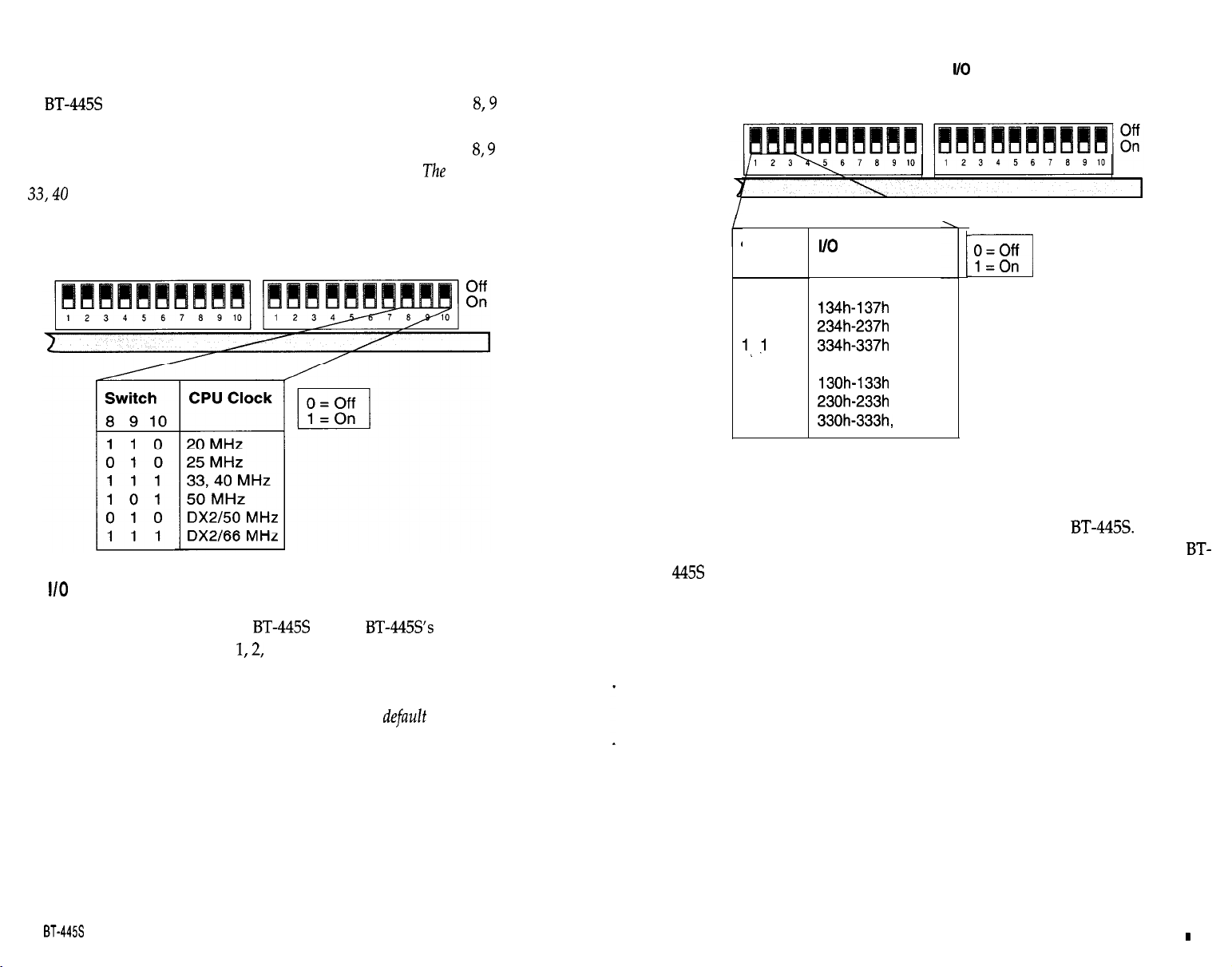
The
supports various VL-Bus clock speeds.
Switches
and 10
of Switch Bay 1 define the VL-Bus clock speed which is the same as the host
CPU clock speed. For a complete list of the settings of Switches
refer to Table 2-2. All other combinations are reserved.
is
Host
MHz.
Switch Bay 2
Port Address
Table 2-2. The VL-Bus Clock Speed
Switch Bay 1
The host communicates with the BT-445s via the
ters.
Switch Bay 2’s Switches
and 3 allow you to define the base I/O
default setting
three I/O regis-
and 10,
address of these three registers within the host I/O map. Note that each
board within the same VL-Bus system must have its own unique I/O re-
gister addresses to prevent hardware conflicts. The
starting address is
330H.
Switch Bay 2 Switch Bay 1
Switch
123
0’0 0
100
010
0
001
101
011
1 1 1
ADDRESS
FUNCTION
Reserved
Reserved
1
Default
Host BIOS (16K Bytes) Address
The BIOS address resides within the host memory map and is executed by
the host even though it is physically located on the
intercepts host interrupt 13H and then dispatches a command to the
for all host to SCSI disk accesses under the DOS environment. Switch
Bay 2’s Switches 4 and 5 select the starting address of a 16K Byte memory
slot within the host memory space for the BIOS.
If more than one host adapter is installed within the same VL-Bus system,
only one can have the BIOS enabled. The BIOS on each additional host
adapter must be disabled. Refer to Table 2-4 for a complete list of these
switch settings.
The default setting is ODCOOOH.
The BIOS
2-6
I
Installation Guide
Unpacking and Installation
2-7
Page 12
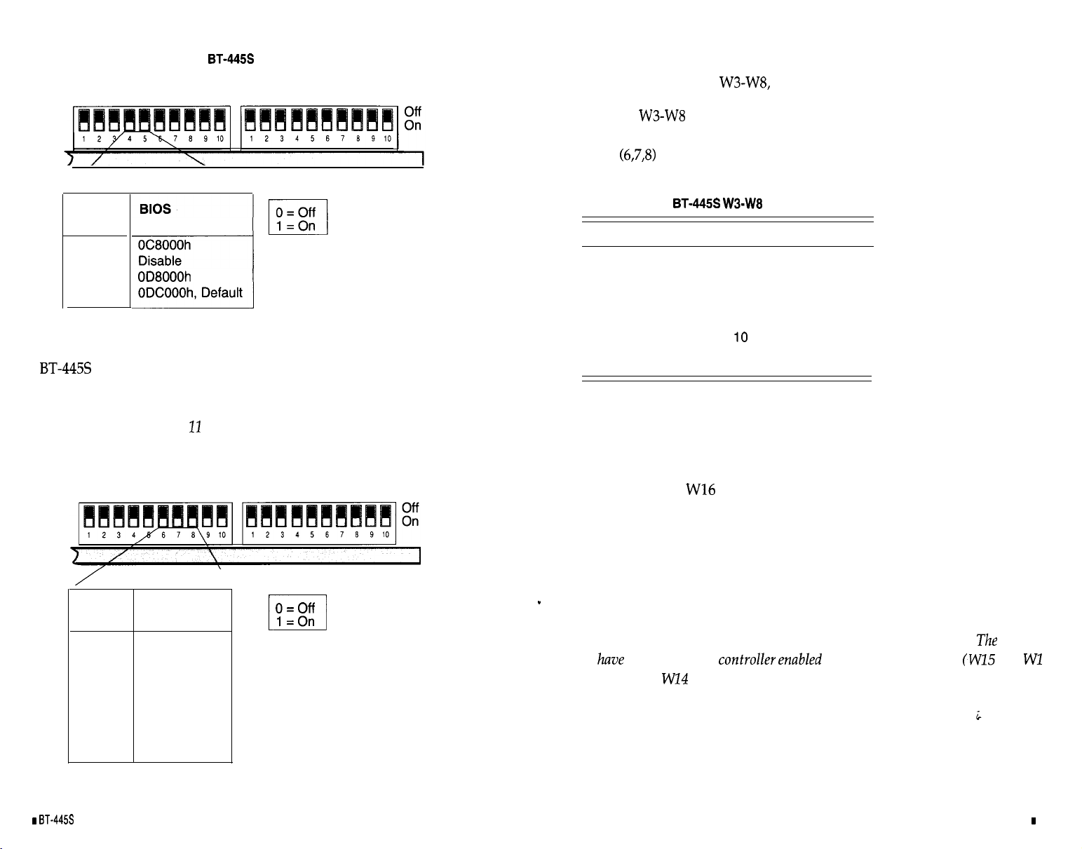
Table 2-4. The
Switch Bay 2
Host BIOS Address
Switch Bay 1
In addition to setting the switch bay for the correct interrupt, make sure that
you also set Jumpers
as described within the next paragraph.
Switch
45
00
1 0
0 1
1 1
ADDRESS
Host Interrupt Request
The
terrupt condition exists.
interrupt channel. Refer to Table 2-5 for a complete listing of these switch
settings. By default, Channel
generates a hardware interrupt to the host whenever an in-
Switch Bay 2’s Switches 6-8 select the host AT
is selected.
Table 2-5. The Host Interrupt Request
Switch Bay 2
Switch Bay 1
Jumpers
set the Host Interrupt Channel. To configure the Host Interrupt Channel properly, check that the corresponding switches in Switch
Bay 2
match the jumper settings shown in Table 2-6. Only one jump-
er must be shorted (installed) for proper operation.
Table 2-6. The BT-44%
Jumper
w3
w4
w5
W6
w7
W8
Jumpers
Host Interrupt Channel
15
14
12
11, Default
9
Switch Bay 2’s Switches 9 and 10 are reserved.
Floppy Subsystem
W14, W15, and
W15 and W16 removed, the floppy disk controller will not respond to read
or write requests from the host. In this case W14 becomes a don’t care.
allow you to configure the floppy subsystem. With
2-8
Switch
678
000
100
010
1 1 0
001
101
011
1 1 1
Installation Guide
CHANNEL
Reserved
Reserved
15
14
12
9
10
11, Default
1 =On
If W15 and W16 are installed, the floppy disk controller is enabled, and will
respond to read or write requests from the host. In this case W14 is used to
select the primary or secondary floppy disk address. When W14 is removed, the primary floppy disk address of 3FX is selected. When W14 is
installed, the secondary floppy disk address of 37X is selected.
to
the floppy disk
installed and
removed).
at the prima y address (WI5 and
Unpacking and Installation
default is
6
2-9
Page 13
SUMMARY OF T HE
SWITCH A ND JUMPER SET=
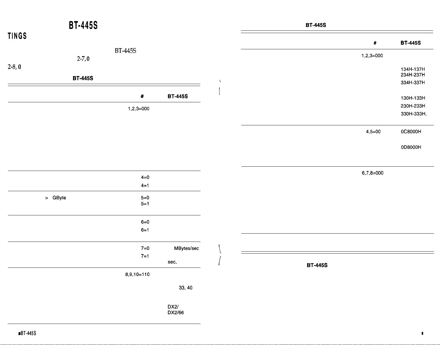
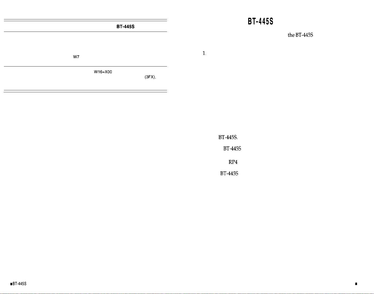
Table 2-7 and Table 2-8 summarize the BT-445s switch and jumper set-
tings, respectively. In Table
represents off and 1 represents on. In Table
represents open and 1 represents closed.
Table 2-7. Summary of the
Host Adapter SCSI ID
SCSI Parity
DOS Disk Space
Adapter Initiate Synchronous Negotiation
Maximum Synchronous Data Rate
VL-Bus Clock Speed (Local CPU Speed) 1 8,9,10=110
1 GByte
Switch Settings
Switch Switch
Bay
1
1
1
1
1
All other combinations are reserved.
100
010
110
001
101 5
011
111
010 CPU 25 MHz
111
101
010 DX2/ 50 MHz
111
1
2
3
4
6
7, Default
Enable, Default
Enable
Disable,
Default
Enable
Disable,
Default
5.0 MBytes/
Default
CPU 20 MHz
CPU
MHz, Default
CPU 50 MHz
Table 2-7. Summary of the
Switch Settings (Continued)
Switch Switch
Bay
Host I/O Port Address
Host BIOS (16K Byte) Address
Host Interrupt Request
Reserved
2 1,2,3=000
2
2 6,7,8=000
2
2 10
Table 2-8. Summary of the BT-445s Jumper Settings
Reserved
100
010
110
001
101
011
111
10
01
11
100
010
110
Reserved
Default
Disable
ODCOOOH,
Default
Reserved
Reserved
15
14
001 12
101 9
011 10
111
9
11, Default
Reserved
Reserved
2-10
Installation
Guide
-Unpacking and Installation
2-11
Page 14
Jumper #
INSTALLING THE
Host Interrupt Channel
Floppy Subsystem
W3
w4
w5
W6
W8
W14, W15,
15
14
12
11,
Default
10
9
Disable Floppy
011 Primary Floppy (3FX),
Default
111 Secondary Floppy (37X)
Complete the following steps to install
in a VL-Bus slot and to
connect it to other devices.
Remove power from the VL-Bus system.
Referring to the VL-Bus system owner’s manual, open the case to
2.
gain access to the motherboard and expansion slots. If the computer
has been on, wait a few minutes until the power supply case has
cooled down inside the computer. If the power supply case is cold,
touch it to discharge any static electricity that may be on your clothes
or body. If a disk controller drive board has been installed, remove
all connecting cables to the board and then lift it out of the host
computer.
Remove the mounting screw and the existing bracket from the rear
3.
panel behind the VL-Bus slot that has been selected for insertion of
4.
the
If the
The slot closest to the disk drives is the best choice.
will be installed in a VL-Bus system which is not at
either end of the SCSI bus, terminators RI’4 and RI’5 must be removed.
The
and RI’5 are 110 ohm resistor packs.
is shipped with terminators installed. For more information on device termination, refer to the next heading, “Host
Adapter Integration”.
2-12
installation Guide
Unpacking and installation
2-13
Page 15
Front of VL-Bus System
Card Cage Slot Guides
Rear
VL-Bus System
8.
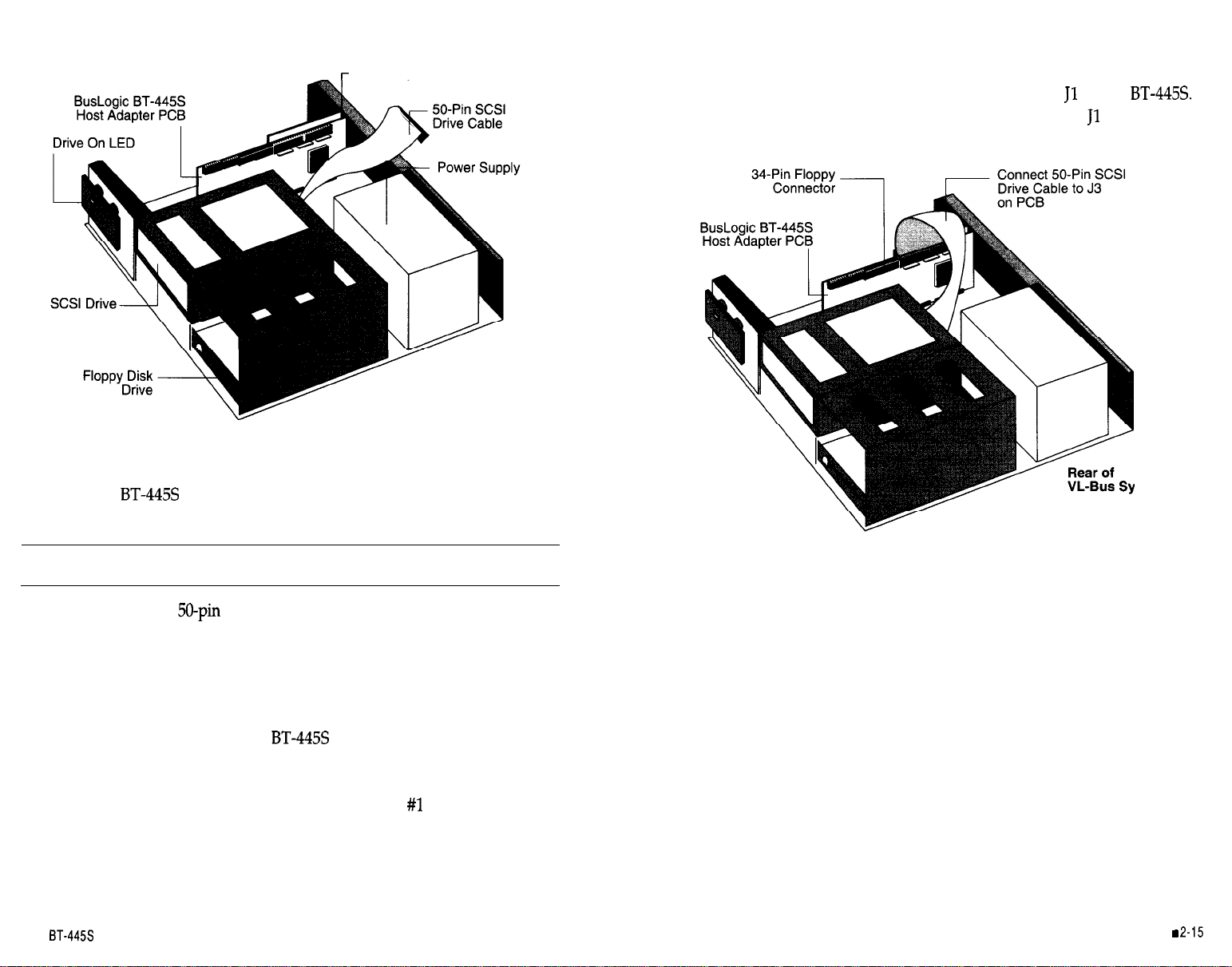
Insert the four-pin header connector from the drive activity LED on
the front panel of the VL-Bus system to connector
This connector is reversible and may be plugged into
on the
in either
direction.
of
5.
Press the
downward into the selected VL-Bus slot, align the
mounting bracket, and reinstall the mounting screw.
Caution:
6.7.Connect the large
Make sure that the board is properly seated in the slot.
connector within the VL-Bus system to the
single-ended SCSI connector, J3. Place the connector cable around the
power supply and over any other boards. Depending on the configuration of your computer, other types of cables could be used.
See the
heading “Cabling Requirements” later in this manual for details.
If the floppy controller on the
will be used, connect the
smaller 34-pin connector from the floppy disk drive to the J2 connector marked
The dark stripe on the cable indicates where Pin
2-14 I BT-44% installation Guide
Floppy.
Make sure the ribbon cable is installed correctly.
is connected.
stem
Front of VL-Bus System
9.
Verify that all connections are secure.
10. Reattach and close the cover of the VL-Bus system as described in
the system owner’s manual.
Unpacking and Installation
Page 16
HOST ADAPTER INTEGRATION
Cabling Requirements
This section describes device termination, cabling requirements, and SCSI
device ID selection.
Device Termination
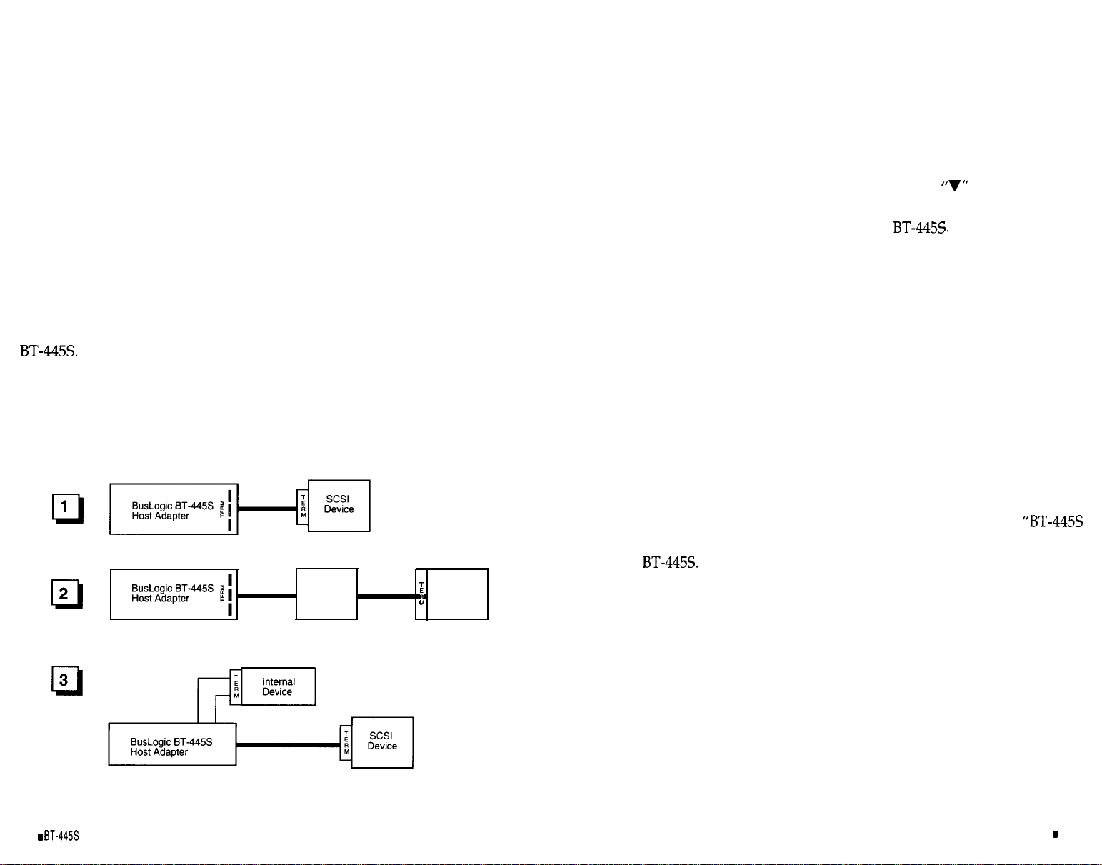
SCSI devices are daisy chained together with a common cable. All SCSI
devices operate on common signals and both ends of the cable are terminated with hardware terminators. Terminators, which can be connected to
either SCSI devices or SCSI cables, are required to make data transfers on
the SCSI bus reliadle.
Devices connected to SCSI chains must have the correct number of terminators for proper operation and to prevent damage to the SCSI chip on the
There can be no more than two terminators in a chain of SCSI
devices-one at each end of the physical chain. Thus if more than two SCSI
devices are connected in a SCSI daisy chain, the middle device(s) in the
control cable must have the terminator resistor packs on the device(s)
removed. See Figure 2-1 for possible configurations of terminators in a SCSI
system.
1
2
SCSI
Device
SCSI
Device
Selecting the proper SCSI cable for a particular system configuration is
of great importance. If two or more SCSI devices are configured in a SCSI
daisy chain, the devices must be connected by a .%-conductor, daisy-chain
cable.
Before plugging in cable connectors, check that the
mark molded on
the connector or the colored stripe on the cable (indicating the location of
Pin 1) matches Pin 1 of the connector on the
SCSI Device ID Selection
The SCSI ID is a number between 0 and 7 assigned to any SCSI device. The
SCSI ID number is used by the computer to communicate with the devices
connected to it. All SCSI devices must have a unique SCSI number to
identify it on the SCSI chain. When two or more SCSI devices communicate, a SCSI device is usually fixed as either an initiator or a target; however,
some devices are capable of performing either role. Devices with higher
ID numbers have a higher priority in communicating with the computer.
Most SCSI peripheral devices are shipped with a preassigned SCSI ID
number. A SCSI ID switch is usually located on the back panel of such
devices. Change the SCSI ID of other peripheral devices only as recom-
mended in the owner’s manual. Refer to the earlier heading
Switch and Jumper Settings” for information on setting the SCSI ID number
of the
2-16
3
BT-44%
Installation
Figure 2-1. SCSI Terminator Configurations
Guide
Unpacking and Installation
2-17
Page 17

HARD DISK INITIALIZATION
This section describes the system set up, initialization, partitioning and for-
matting of hard disk drives used with the
erase all data on your disk drives. Before following these procedures make
sure that all necessary data is backed up on another drive.
Set-up, Initialization, and Partitioning Procedure
To perform set up, initialization, and partitioning, proceed as follows:
These procedures will
A) The SCSI Fixed Disk Format utility appears on the screen. Enter
1
to view the attached devices and then press
SCSI Fixed Disk Format Utility
Show all installed drives
1.
2. Select next drive
3.
Format current drive
4.
Verify current drive
5.
Quit (exit to DOS)
<RETURN>.
1.
After plugging in and connecting the
(see the previous parts
of this section), apply power to the VL-Bus system.
2.
Insert the system diagnostic diskette in the drive, or execute the
host’s internal diagnostic/set-up program. See your particular
system’s installation instructions.
3.
In accordance with the menu that appears on the system monitor,
run
SETUP
disk option for SCSI drive to
and configure the host CMOS RAM options. Set the hard
No Hard Drive Installed.
The following Steps 4 through 8 may not be necessary if your SCSI hard
disk drive has already been formatted.
Reboot the VL-Bus system and insert the DOS diskette containing
4.
the
DEBUG
After the DOS prompt, type the following for low-level format:
5.
debug <RETURN>
The system responds with the
A)
Type
program.
prompt.
the host BIOS address is set for this;
otherwise, enter the correct BIOS address.
Enter Your Option: _
A list of all attached drives appears under the option prompt.
Press the
key until the drive to be formatted is the current
drive.
Press
3
<RETURN>
to
format the drive. The following prompt
appears:
All data on this drive will be lost!
Proceed with low level formatting? (Y/N) _
Enter Y to proceed with low-level formatting and follow the
instructions as they appear on the screen.
The system will format the SCSI drive selected. When the format
is completed, press any key to go back to the main menu shown
in the preceding Step 6A. Enter
press
<RETURN>.
All data on this drive will be verified.
The following prompt appears.
to verify the drive and then
Perform the following steps on your screen monitor to configure and
6.
perform a low-level format on attached devices:
2-18
BT-44%
Installation
Guide
Proceed with low level verification? (Y/N) _
Enter Y to proceed with verification.
Unpacking and Installation
2-19
Page 18
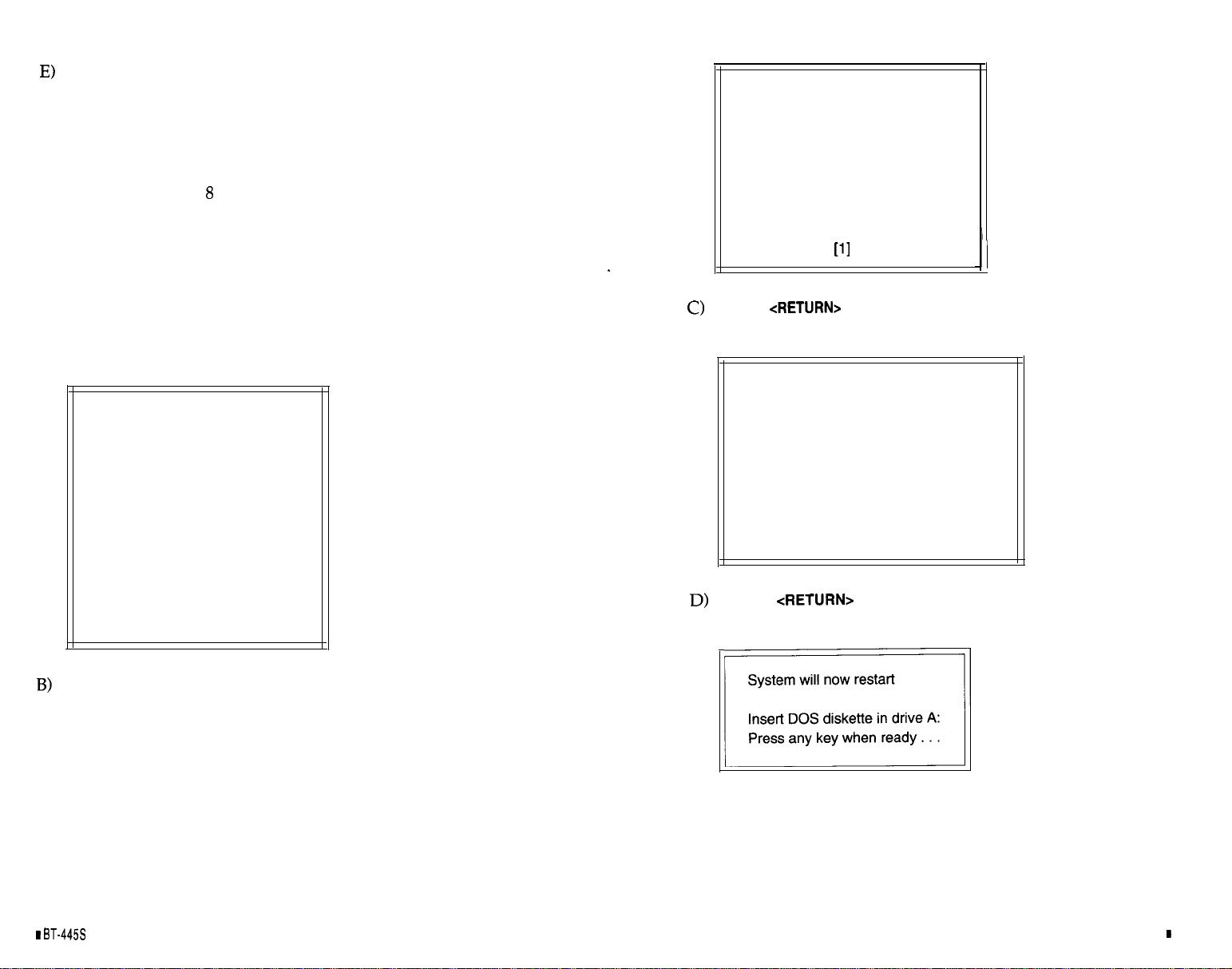
When the verification is finished, press any key to go back to the
main menu shown in the preceding Step 6A. To exit to DOS,
type:
5 <RETURN>
The following Steps 7 and
to be installed is not DOS.
may not be necessary if the operating system
Create DOS Partition
Current Fixed Disk Drive: C
Choose one of the following:
1. Create Primary DOS Partition
2. Create Extended DOS Partition
7.
Run the DOS FDISK program to partition the disk for the number of
cylinders to be used by DOS. The following steps are recommended
for users who are not familiar with the DOS FDISK program. See
your DOS manual for information on the FDISK command.
A) Enter fdisk <RETURN>. The following menu appears.
FDISK Options
Current Fixed Disk Drive: C
Choose one of the following:
1. Create DOS Partition
2. Change active Partition
3. Delete DOS Partition
4. Display Partition information
Enter Choice: [I]
Enter
1 <RETURN> to create
a DOS partition. The following
menu appears.
Enter Choice:
Enter
1 <RETURN>
to create a primary DOS partition. The next
menu appears.
Create
Current Fixed Disk Drive: C
Choose one of the following:
Do you wish to use the maximum size
for a DOS partition and make the DOS
partition active
Enter
Primary DOS Partition
(Y/N) . . . . . . . . . . . . . . . . . . ...?
Y <RETURN> to create a
[Y]
primary DOS drive partition with
the maximum size. The following prompt appears.
2-20
Installation
Guide
When the partitioning has been completed (indicated by another
prompt), press any key to return to DOS.
Unpacking and Installation
2-21
Page 19
8.
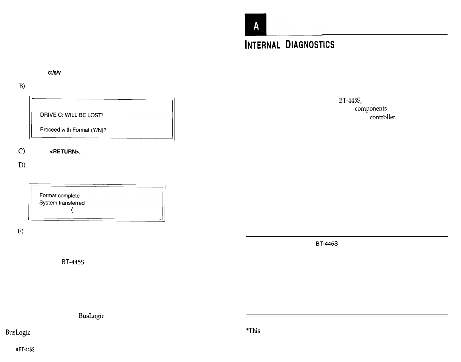
Install DOS by running the FORMAT program as instructed by DOS
normal installation procedures. The next steps are recommended for
operators who are not familiar with the DOS FORMAT program.
A) Run the FORMAT program by typing:
format
<RETURN>
The system displays the following format warning:
WARNING: ALL DATA ON NON-REMOVABLE DISK
Type Y
When the format has been completed, the following prompt
appears.
Volume label
11 characters, ENTER for name )?
Enter any legal file name to label the volume just created. Refer
to your system operator’s manual for more details on the DOS
format procedures.
This concludes the
hardware and software installation proce-
dures.
WARRANTY INFORMATION
If damage to the board has occurred, return it in the protective envelope
with this manual to your
should also be notified if the unit has been damaged during shipment. The
warranty conditions are given in the back of this manual.
board supplier. The shipping agent
When power is first applied to the
is run to verify that the major functional
an on-board diagnostic routine
of the board are operating correctly. The bus master chip, the SCSI contioller chip, the firmware
PROM, the local RAM and internal data buses are tested. Results of the tests
are indicated by an LED on the board.
The LED will first turn on when power is applied. If the diagnostics find no
malfunctions, the LED will then go off. In normal operation, the LED will
be illuminated when command or SCSI bus activity occurs on the board.
If an error is detected by the diagnostics, the LED will repeatedly flash a
specific number of times, with a long pause between flashes, to indicate the
board function which failed. This will continue until the board is powered
down or reset.
Failure interpretation from the number of flashes is as fol-
lows:
Number of LED Flashes
Always On
1
2
3
4
5
6
7
Constantly Flashing
Interpretation of Failure
Firmware ROM checksum failure
Local RAM test failure
SCSI controller chip or SCSI interface failure
Internal data bus failure
internal address bus failure
Bus master chip failure
SCSI drive type mismatch’
Fuse blown
error message is only applicable to the differential SCSI host adapters
when single-ended SCSI drives are connected to the differential SCSI bus.
2-22
Installation Guide
Internal Diagnostics I A-l
Page 20
l
Page 21

PRODUCT S UPPORT R ECORD
The information on this page should be compiled and provided
to your supplier in writing to obtain technical support assistance. This will enable your supplier to respond more rapidly
and more appropriately to your problem.
About
Serial Number:
Date of Purchase:
Firmware Version Number:
BIOS Version Number:
Purchased From:
Company:
Address:
Purchased By:
Name/Title:
Company:
Address:
Telephone
About System Hardware Configuration:
System Manufacturer:
System Model and Speed:
System BIOS Manufacturer:
Memory in System:
Hard Drives on System:
Product:
Product No:
About System Software Configuration:
Operating System/Version:
Application Program/Version:
Detailed Description of Problem:
Page 22
 Loading...