

Page 1
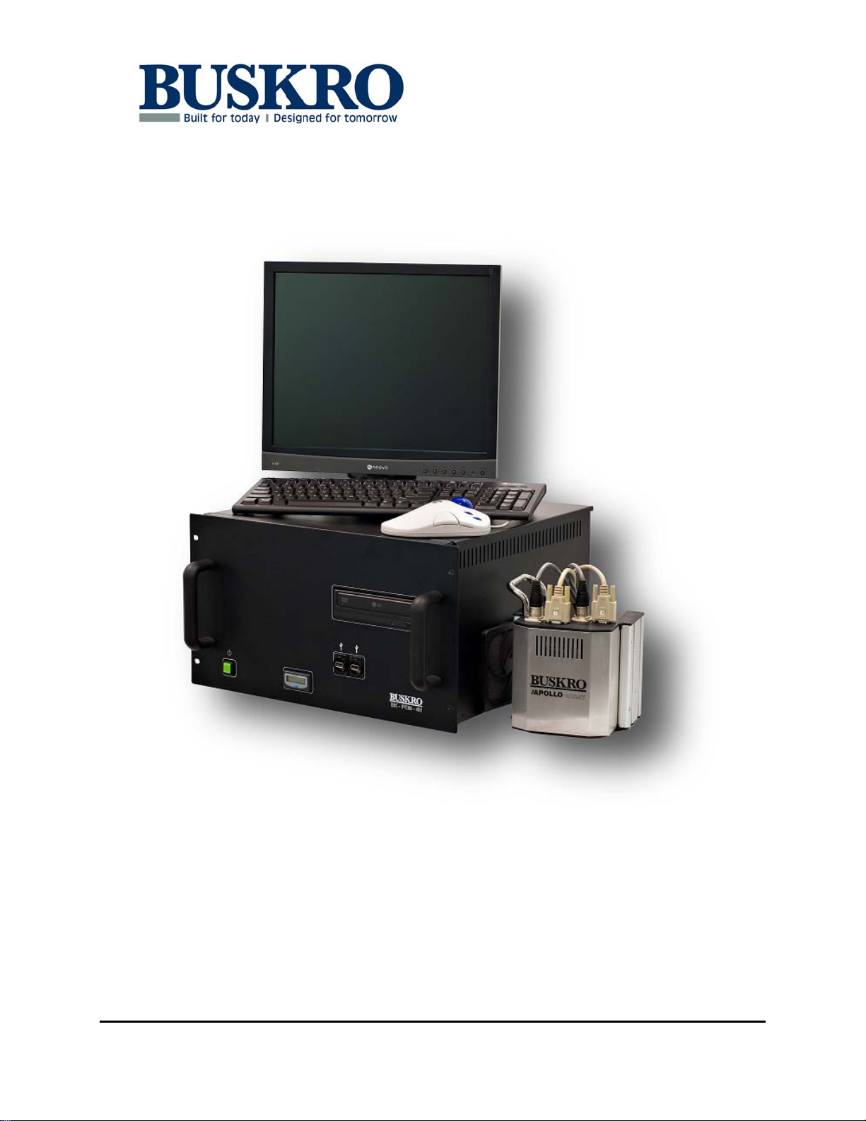
BK705 Ezejet Controller
Part No. 9104450 User’s Guide V1.1
Page 2
BK705 Ezejet Controller User’s Guide
Published by:
Buskro Ltd.
1738 Orangebrook Court, Unit #1
Pickering, ON, L1W 3G8
Canada
Tel.: (905) 839-6018
Fax: (905) 839-6023
All Rights Reserved. No part of this book may be used or reproduced in any form or by
any means, electronic or mechanical, or stored in a database or retrieval system,
without prior written permission of Buskro Ltd. except in case of brief quotations
embodied in critical articles or reviews. Making copies of any part of this book for any
purpose other than your own personal use is a violation of copyright laws.
Copyright © 2007 Buskro Ltd.
First Edition, 2007
Printed in Canada
This manual is sold as is, without warranty of any kind, either express or implied,
respecting the contents of this manual, including but not limited to implied warranties for
the manual’s quality, performance, merchantability, or fitness for any particular purpose.
Neither Buskro Ltd. nor its dealers or distributors shall be liable to the purchaser nor any
other person or entity with respect to any liability, loss, or damage caused or alleged to
be caused directly or indirectly by this manual.
Manual History
Version Date Description ECO No.
1.0 06-Aug-07 Release of manual. N/A
1.1 02-Sep-08 Expanded Manual to include Atlas and Aurora 1088
Buskro Ltd. BK705 Ezejet Controller
Page 3

BK705 Ezejet Controller
Table Of
Contents
1.0 General Information.............................................................................1-0
1.1 Description ............................................................................................................ 1-1
1.1.1 Controller Stand (P/N BK705-ST)................................................................... 1-1
1.2 Specifications......................................................................................................... 1-3
1.2.1 Dimensions ...................................................................................................... 1-3
1.2.2 Approximate Weight Specifications................................................................ 1-5
1.2.3 Electrical Specifications .................................................................................. 1-5
2.0 Controller Components ........................................................................2-0
2.1 Atlas/Aurora Inkwell Module (IWM) ................................................................ 2-1
2.1.1 Atlas System Support Board (ASSB)..............................................................2-1
2.1.2 System Support Board CPU II (SSB CPU II).................................................. 2-2
2.1.3 Head Drive Circuit Board (HDC).................................................................... 2-4
2.1.4 Lung Vacuum................................................................................................... 2-5
2.1.5 Ink Supply Line................................................................................................ 2-6
2.1.6 Maintaining the Ink Line ................................................................................. 2-7
2.1.7 Replacing the Ink Bottle .................................................................................. 2-8
2.1.8 Peristaltic Pump Head...................................................................................... 2-8
2.1.9 Pressure Regulator.........................................................................................2-10
2.2 Apollo Ink Delivery Module (IDM) .................................................................. 2-11
2.3 Power Supply Module........................................................................................2-13
2.4 Field Connection Board ..................................................................................... 2-14
2.5 Datapath and Image Accelerator Card............................................................2-15
2.5.1 Image Accelerator Card Diagnostics.............................................................2-17
2.5.2 Firmware Updates.......................................................................................... 2-17
2.6 Optional Hardware............................................................................................. 2-19
2.6.1 Serial Card (P/N BK-COMM)....................................................................... 2-19
2.6.2 Expansion Board (P/N BK-EXP-1700)......................................................... 2-19
2.6.3 Image Accelerator Expansion Module (P/N BK-EXP-IAC)......................... 2-19
2.6.4 Tracking Board (P/N BK-TRACK-1700)...................................................... 2-19
2.7 Grounding ........................................................................................................... 2-21
3.0 Compose IQ............................................................................................3-0
3.1 Introduction .......................................................................................................... 3-1
3.2 Host/Client Mode.................................................................................................. 3-2
3.2.1 Client Mode ..................................................................................................... 3-2
3.2.2 Host Mode........................................................................................................ 3-2
3.3 OCR Mode............................................................................................................. 3-2
3.4 Selective Inserting Mode...................................................................................... 3-3
3.5 Compose IQ Dongle.............................................................................................. 3-3
3.6 Compose Software................................................................................................ 3-3
Buskro Ltd. BK705 Ezejet Controller
Page 4

3.6.1 Printhead Drivers............................................................................................. 3-4
3.6.2 Diagnostics Screen........................................................................................... 3-4
Appendix A – General Assembly Drawings
Appendix B – Ink Specific Assembly Drawings
Appendix C – Power Supplies Assembly Drawings
Appendix D – Electrical Drawings
Appendix E – Field Connection Board
Appendix F – Serial Communication
Buskro Ltd. BK705 Ezejet Controller
Page 5

General Information
1.0 General Information
Chapter 1
Buskro Ltd. BK705 Ezejet Controller
Page 6
Chapter 1 General Information Page 1-1
1.1 Description
The BK705 Ezejet Controller is an entry-level print system utilizing Compose IQ software.
It is capable of supporting either Thermal Ink-Jet (TIJ) technology (Apollo or full-process
color with the Apollo-4C) or Piezoelectric Ink-Jet technology (Atlas or Aurora). A
summary of some of the capabilities of each controller type can be found in Table 1-1.
Table 1-1: Buskro Controller Summary
Support BK705 BK1705 BK1710 BK1720
Compose IQ Yes Yes Yes Yes
Tracking Option Capable Yes Yes Yes Yes
Combo Option Capable (e.g. Atlas & Apollo) No Yes Yes Yes
Max. inches Apollo (1 to 4” Printheads) 4” 8” 16” 16”
Max. # Apollo-4C Printheads 1 2 4 4
Max. # Atlas or Aurora Printheads 2 4 4 8
Max. inches of Atlas or Aurora Print 3” 4” 12” 24”
Max. # Atlas or Aurora 1250 Printheads (1”) 2 4 4 8
Max. # Atlas or Aurora 2250 Printheads (2”) 2 2 4 8
Max. # Atlas or Aurora 3250 Printheads (3”) 0 0 4 8
Note: The maximum number of printheads or inches of print listed above are based on a
single technology application. These values may be different in combo
applications.
1.1.1 Controller Stand (P/N BK705-ST)
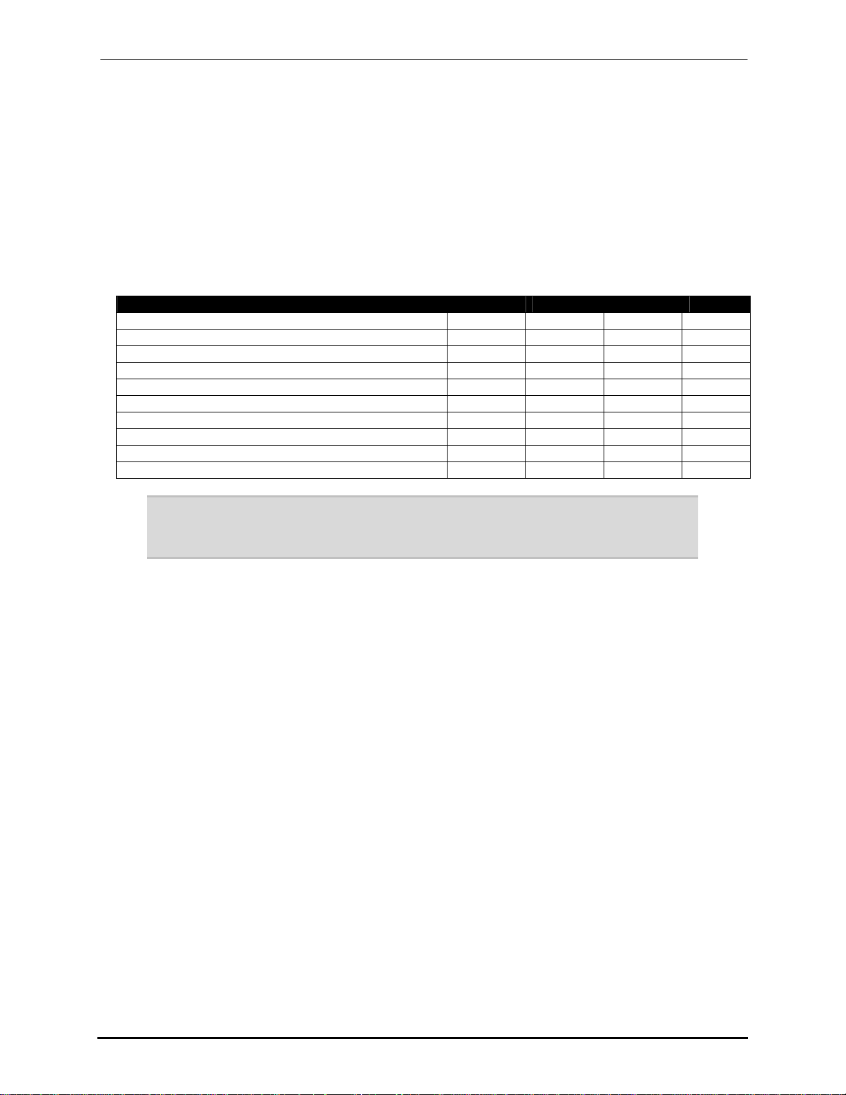
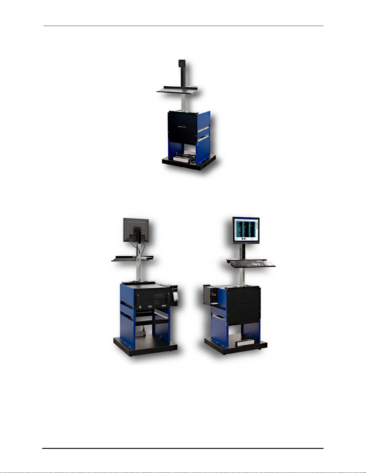
The controller stand (Figure 1-1) provides a clean method of housing the BK705
components and options (Figure 1-2). It is optional for Apollo systems, but mandatory for
all other technologies. It is also supported on four caster wheels to easily move the whole
controller around. It can house the computer module, a separate power supply module, an
Ink Delivery unit, and computer peripherals such as the monitor, keyboard, and trackball.
For increased flexibility and comfort, the stand also provides the ability to set the height
of the monitor as well as the position of the keyboard by adjusting it along the aluminum
extrusion rails. This can be done by loosening the mounting screws, repositioning the
monitor or keyboard tray, and retightening. A description of the range of adjustment can
be seen in Section 1.2.
Buskro Ltd. BK705 Ezejet Controller
Page 7
Chapter 1 General Information Page 1-2
Figure 1-1: BK705 Controller Stand (P/N BK705-ST)
Figure 1-2: BK705 Integrated with Stand and Apollo Ink Delivery Module
Buskro Ltd. BK705 Ezejet Controller
Page 8
Chapter 1 General Information Page 1-3
1.2 Specifications
1.2.1 Dimensions
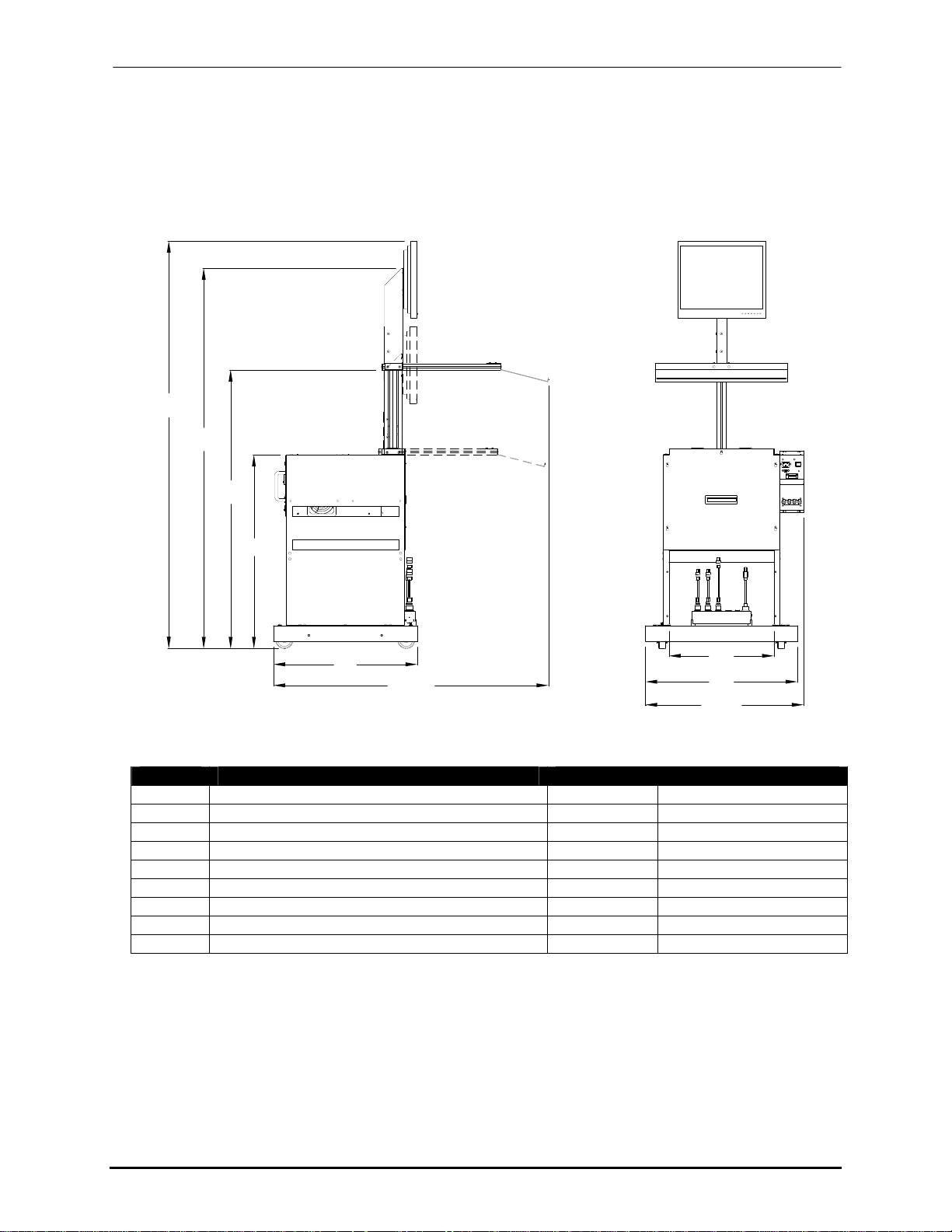
1.2.1.1 Controller Stand (BK705-ST)
O.H.
Y1
Y2
Y3
X1
O.W.
X3
X2
O.L.
Table 1-2: BK705-ST Dimensions
Symbol Description Dimensions
O.H. Overall Height (17” LCD Shown) 55.7 - 68.4 in 1415 - 1738 mm
O.L. Overall Length 26.8 in 680 mm
O.W. Overall Width 32.3 - 46.5 in 821 - 1182 mm
X1 Width of base 24.3 in 618 mm
X2 Length of base 25.7 in 653 mm
X3 Entrance length of lower cabinet 17.8 in 451 mm
Y1 Height of stand without monitor 54.6 - 64.8 in 1388 - 1646 mm
Y2 Height to keyboard stand 33.9 - 47.3 in 860 - 1200 mm
Y3 Height of cabinet 32.9 in 835 mm
Buskro Ltd. BK705 Ezejet Controller
Page 9
Chapter 1 General Information Page 1-4
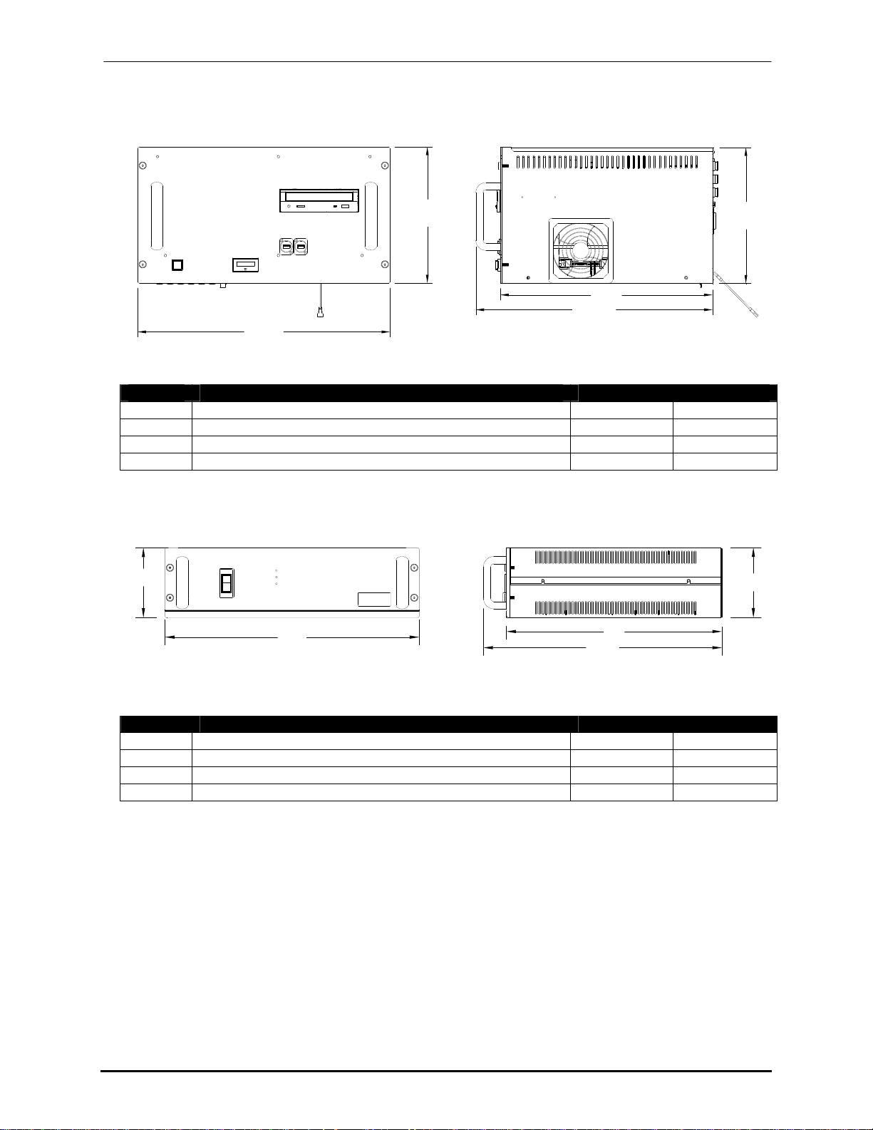
1.2.1.2 BK705 Computer Module (BK-PCM-4H and BK-PCM-8)
O.H.
X1
O.W.
O.L.
Table 1-3: BK-PCM-4H and BK-PCM-8 Dimensions
Symbol Description Dimensions
O.H. Overall Height 10.35 in 263 mm
O.W. Overall Width 18.05 in 458 mm
O.L Overall Length 19.20 in 488 mm
X1 Width of chassis 16.18 in 411 mm
1.2.1.3 Apollo Power Supply Module (BK-PSM-4H)
O.H.
O.H.
O.H.
O.L.
X1
O.W.
Table 1-4: BK-PSM-4H specifications
Symbol Description Dimensions
O.H. Overall Height 5.27 in 134 mm
O.W. Overall Width 18.00 in 457 mm
O.L Overall Length 19.19 in 487 mm
X1 Width of chassis 16.27 in 413 mm
Buskro Ltd. BK705 Ezejet Controller
Page 10
Chapter 1 General Information Page 1-5
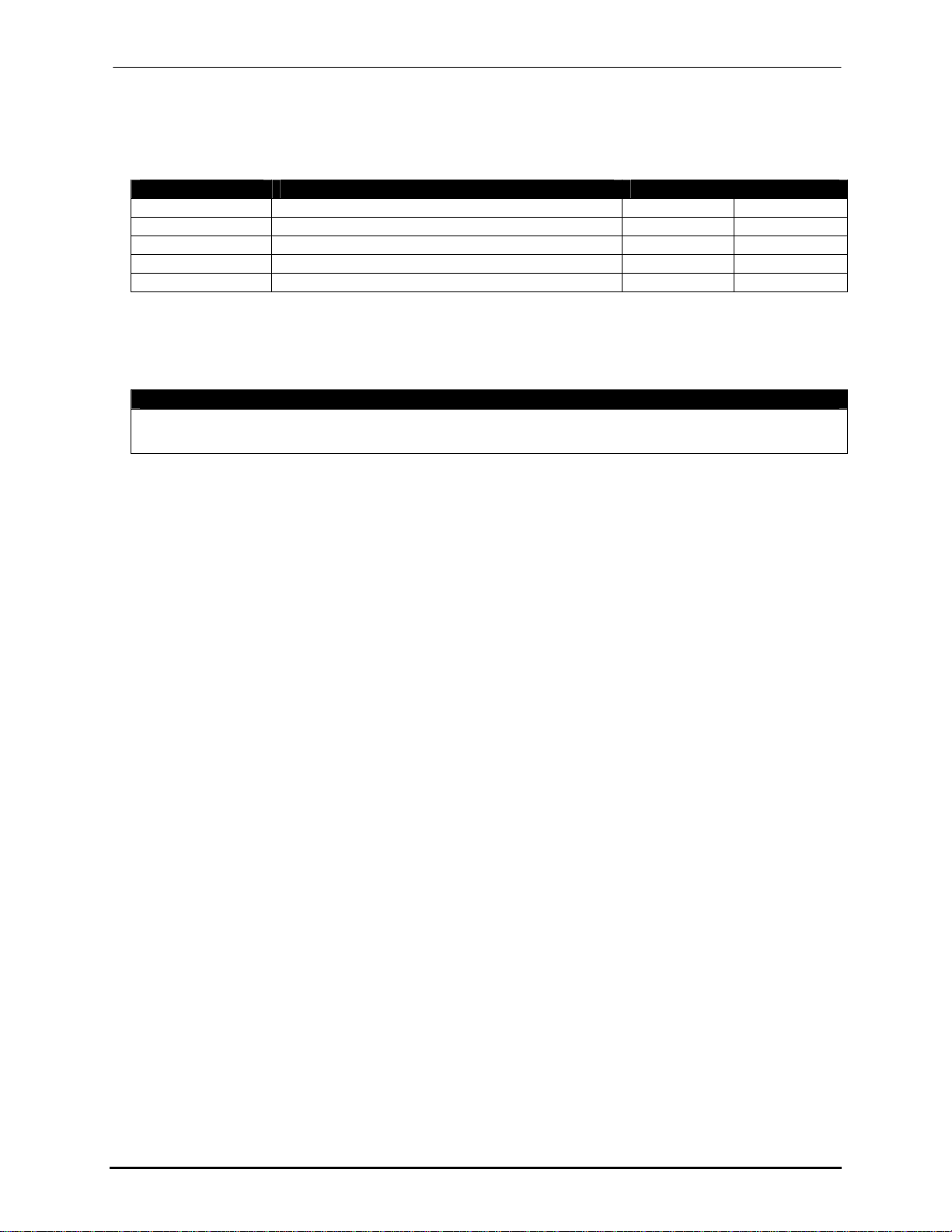
1.2.2 Approximate Weight Specifications
Table 1-5: Approximate Weight Specifications (Values are subject to changes)
Part # Description Weight
BK-MON-LCD17 Monitor, LCD, 17in (Box Included) 14 lb 6.4 kg
BK-PCM-4H Module, Computer, BK705 42 lb 19 kg
BK-PSM-4H Module, Apollo Power Supply, 4 channel 27 lb 12.3 kg
BK-IDM-4H Module, Ink Delivery, 4 channel 10 lb 4.5 kg
BK705-ST Stand, Apollo EzeJet Controller 94 lb 42.6 kg
1.2.3 Electrical Specifications
Table 1-6: BK705 Electrical Specifications
Electrical Requirements
Input Line Voltage
Current
100-120, 200-240 VAC
5 A
Buskro Ltd. BK705 Ezejet Controller
Page 11

Controller Components
2.0 Controller Components
Chapter 2
Buskro Ltd. BK705 Ezejet Controller
Page 12
Chapter 2 Controller Components Page 2-1
2.1 Atlas/Aurora Inkwell Module (IWM)
The Inkwell Module for the Atlas (Monet or Cezanne) and Aurora (Renoir) technologies
consists of the ink delivery components and all related electronics. By default, the Atlas and
Aurora inkwells include support for up to two printheads on the BK705.
2.1.1 Atlas System Support Board (ASSB)
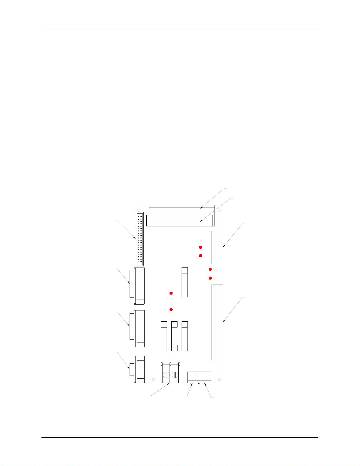
The Atlas System Support Board (Figure 2-1) interconnects all the components required to
drive the print system. It also monitors and controls the ink level in the printhead and sets
the fire-pulse amplitude delivered by the HDC to the printhead. The main connections on the
ASSB are summarized in Table 2-1.
Figure 2-1: Atlas System Support Board
HDC #1
SSB CPU
Head Support
Cable #2
Head Support
Cable #1
Datapath
COMM Cable
J1
J7
ATLAS ATLAS
J10
APULSEB
APULSEA
J9
FIREA-
FIREA+
FIREB+
AGNDB
AGNDA
UMB2
D4
UMB1
D3
F3
F2 F1
NEUTRAL
J3 J2
HDC #2
J6
HV
+12
GND
GND
DACB
DACA
FIREB-
F4
LINE
GND
SPEED
+12
VLV2
D6
+12
D5
VLV1
+12
J4
INKREF
D8
VACREF
D7
LOIS
GND
GND
THERM
RV
GND
BDC
HEAT2
HEAT2
MOT-
MOT+
FUSE
FUSE
HEAT1
HEAT1
J5
GND
GND
+12
+12
HV
J8
Pressure Regulator
Ink Delivery System
110 VAC
+12 VDC
+170 VDC
+12 VDC
Buskro Ltd. BK705 Ezejet Controller
Page 13

Chapter 2 Controller Components Page 2-2
Table 2-1: Atlas System Support Board Connections
Component Description
J1 Connection for System Support Board CPU (SSB CPU)
J2 Connection for Atlas Power Supply (12 VDC)
J3 Connection for incoming power (120 VAC)
J4 Connection for the pressure regulator
J5 Connection for the Ink Delivery System (IDS)
J6 Connection for the Head Drive Circuit Board (HDC)
J7 Connection for the Head Support Cable #1
J8 Connection for the Atlas Power Supply (+170 VDC, +12 VDC)
J9 Connection for the Head Support Cable #2
J10 Connection for the Datapath Card Cable
F1 Fuse, +12 VDC (2 A)
F2 Fuse, 120 VAC Line (3 A)
F3 Fuse, 120 VAC Neutral (3 A)
F4 Fuse, +12 VDC (1 A)
D3 UMB #1 LED indicates printbar #1 solenoid valve is open (printbar filling with ink)
D4 UMB #2 LED indicates printbar #2 solenoid valve is open (printbar filling with ink)
D5 Priming Valve #1 LED indicates priming valve #1 is active
D6 Priming Valve #2 LED indicates priming valve #2 is active
D7 Vacuum Refresh LED (On Elite only)
D8 Ink Pump LED indicates that ink is being pumped from the IDS
2.1.2 System Support Board CPU II (SSB CPU II)
The System Support Board CPU II (Figure 2-2) provides the intelligence for the ASSB. The
SSB CPU II performs the following functions:
1. Communicates with the Image Accelerator Card via the ASSB to display error icons
and printhead temperature and voltage readings.
2. Controls opening and closing of the Ink Supply Line Valve in the printhead.
3. Commands the Pressure Regulator to prime a printhead when the priming button is
pressed.
4. Controls the sequence for refilling the printhead with ink.
5. Controls low-on-ink sensing using the float switch installed in the subcontainer.
Buskro Ltd. BK705 Ezejet Controller
Page 14
Chapter 2 Controller Components Page 2-3
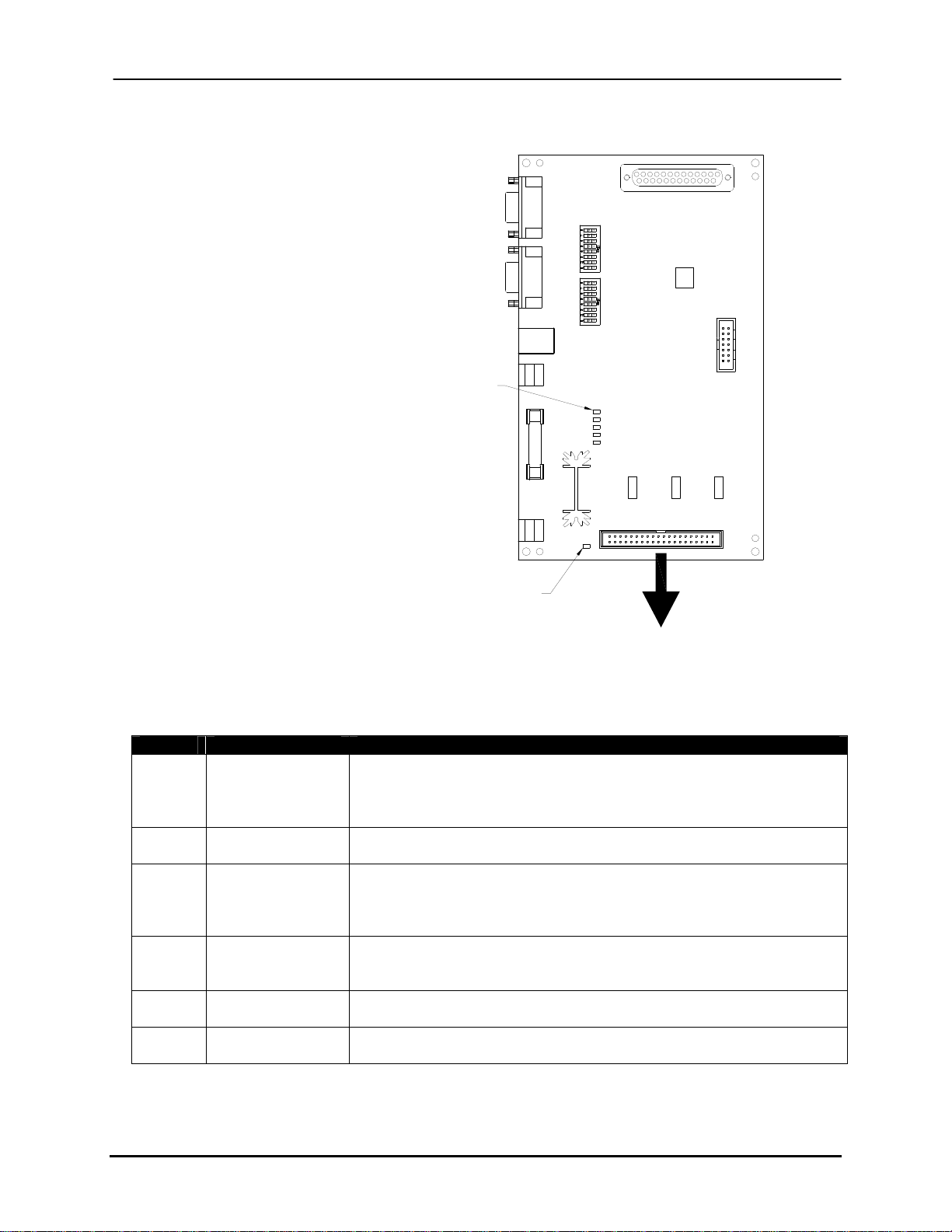
Figure 2-2: System Support CPU II Board
LED1 is illuminated when the system is ON and READY.
LED2 indicates that the sub-container (Atlas)
or the OHS (Elite) is low on ink and must be filled.
LED3 indicates an ink fail has occurred.
LED4 is not used and will always be OFF.
RUN is ON when processor is operating. The LED will blink
if there is a problem with the processor.
Power LED will turn ON
when power is applied to
the board and the fuse is OK.
PWR
S2
S1
RUN
LED4
LED3
LED2
LED1
J4
J1
J2
J3
J5
COM2 COM1
J7
USB
J6
+
RS485
F1
1A
J8
GND
+12V
Atlas Systems: Atlas System Support Interface Cable
P/N 606311A
Connects to System Support Board (J1)
Table 2-2: System Support CPU II Board - S1 DIP Switch Settings (S2 all off, Open = Off)
DIP Setting Function
1 and 2 1:2 = OFF:OFF
1:2 = ON:OFF
1:2 = OFF:ON
1:2 = ON:ON
3 ON
OFF
4 and 5 4:5 = OFF:OFF
4:5 = ON:OFF
4:5 = OFF:ON
4:5 = ON:ON
6 ON
OFF
7 ON
OFF
8 ON
OFF
Buskro Ltd. BK705 Ezejet Controller
For Print Bars 1 and 2
For Print Bars 3 and 4
For Print Bars 5 and 6
For Print Bars 7 and 8
Atlas Printheads
Elite Printheads
IAP 100% Jetting Voltage (for Elite)
IAP 25% Jetting Voltage
IAP 33% Jetting Voltage
IAP 50% Jetting Voltage
10% Printhead Heater Power (For low temperature inks like
Cezanne)
100% Printhead Heater Power
Re-program the Altera CPLD
Normal Mode
Enter Firmware Update Mode
Normal Mode
Page 15
Chapter 2 Controller Components Page 2-4
2.1.3 Head Drive Circuit Board (HDC)
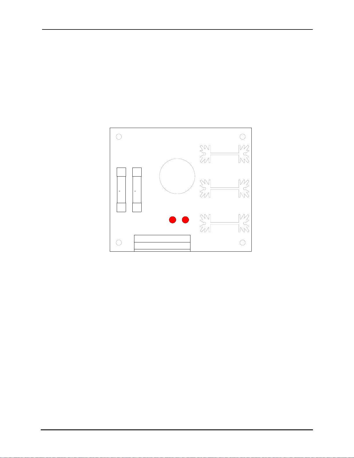
The Head Drive Circuit Board (Figure 2-3) generates the high and low voltage signal
required to fire the printhead and also regulates the printhead voltage. When the low voltage
signal is received by the HDC board, LED D1 turns on. When the high voltage signal is
outputted by the HDC board in order to fire the printhead, LED D6 turns on.
Figure 2-3: Head Drive Circuit Board
F2
F1
12V
130V
1
1
A
A
4
4
D1 D6
GND
+12V
+130V
DAC
FIRE+
FIRE-
OUTA
OUTB
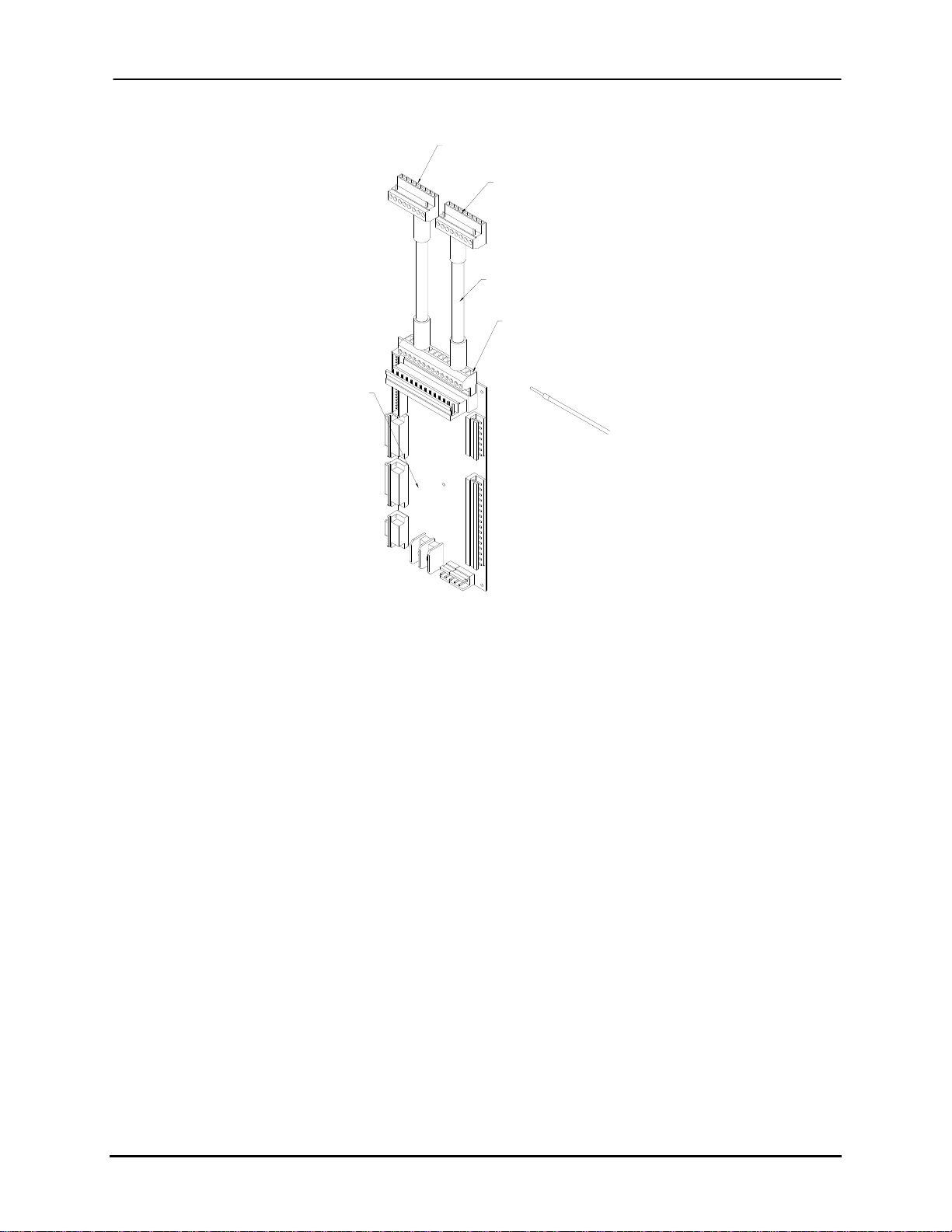
One HDC board is required for each 1250 printhead (1”) while two are required for a 2250
(2”). When a 2250 printhead is utilized, a dual HDC cable (9100510A) replaces the two
single HDC cables (9100197A) and a 12V wire from the 2250 Printhead umbilical is
connected to the 12V contact on the SSB board (Figure 2-4).
Buskro Ltd. BK705 Ezejet Controller
Page 16
Chapter 2 Controller Components Page 2-5
Figure 2-4: Cable connections for 2250 on SSB
To HDC 1
To HDC 2
9100510A
+12 contact
Ç
Ç
System
support
board
(SSB)
Ç
12 VDC "fly" wire
(from umbilical
sleeve assembly)
2.1.4 Lung Vacuum
The purpose of the lung vacuum is to remove gas from the ink which can form bubbles that
cause jetouts. The lung vacuum should measure approximately –23.5 inches of mercury (in
Hg). If the vacuum drops below 14 in Hg, there may be a loss in jets during printing. If a
large volume of ink is purged out at a given time, wait at least two minutes before printing in
order to provide time for the Lung Vacuum to remove trapped gasses in the ink.
Buskro Ltd. BK705 Ezejet Controller
Page 17
Chapter 2 Controller Components Page 2-6
2.1.5 Ink Supply Line
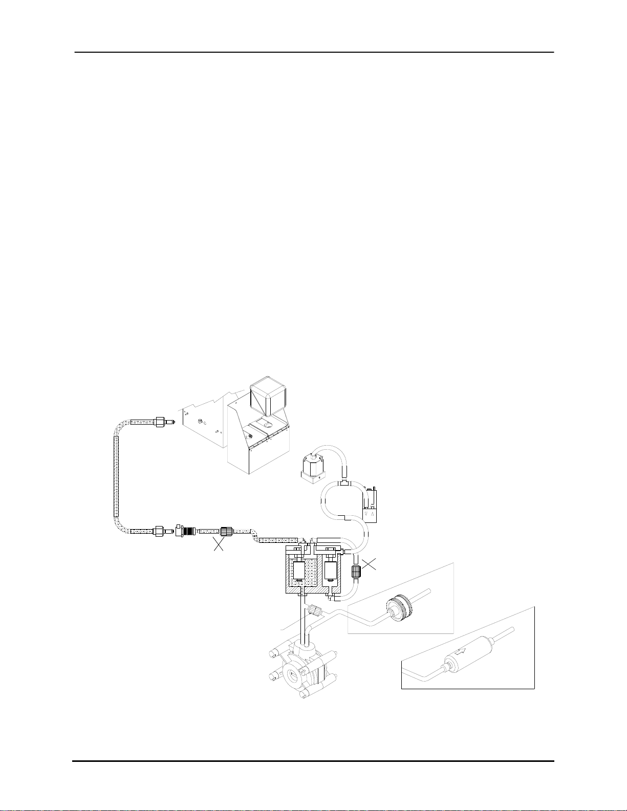
The ink supply line controls the flow of ink from the ink container (located in the ink bottle
holder) to the printhead. The sequence of the ink flow from the container is summarized
below:
1. Ink starts in the ink container and is fed into the subcontainer.
2. The float switch determines if the correct amount of ink is in the subcontainer.
3. The peristaltic pump head pumps ink through the filter. If pressure reaches 20
psi, ink is released back into the subcontainer line through the relief valve.
4. The hydrophilic filter filtrates ink before exiting the inkwell.
5. Ink travels from the inkwell to the printhead through the umbilical.
6. The printhead solenoid valves open and close to supply ink to each printbar
individually.
Figure 2-5: Ink Supply Line
Ink line
Æ
Check valve
(9104674)
4 PSI
Æ
Æ
Check valve
(9101700)
20 PSI
Æ
Æ
Solenoid valve
Normally open
(9104711)
Æ
Æ
Æ
Æ
Æ
Æ
Æ
Æ
LOCK
Æ
Æ
Æ
Pump
(9104662)
Æ
Æ
Check valve
(9104671)
1 PSI
Æ
Print head
Filter holder
assembly -
Monet, Cezanne
(9100964A)
Æ
Æ
Print head
Peristaltic
pump
(9100931)
Æ
Filter holder
assembly -
Renoir
(9103390A)
Buskro Ltd. BK705 Ezejet Controller
Page 18
Chapter 2 Controller Components Page 2-7
2.1.6 Maintaining the Ink Line
In order to ensure optimum performance, it is important to replace the relief valve, filter, and
the tubing once every six months. In order to do this, refer to the following instructions:
1. Turn off the system and wear splash safety goggles and gloves before any
maintenance work is done. Use caution as ink lines can be pressurized.
2. Using a flat-head screwdriver, turn the peristaltic pump clockwise in order to remove
ink from the ink line between the pump and the relief valve.
3. Replace the relief valve. The arrow on the relief valve must point towards the
subcontainer line.
4. Replace the filter. Note that the filter used depends on the type of ink (See Appendix
B for the part number of the proper filter).
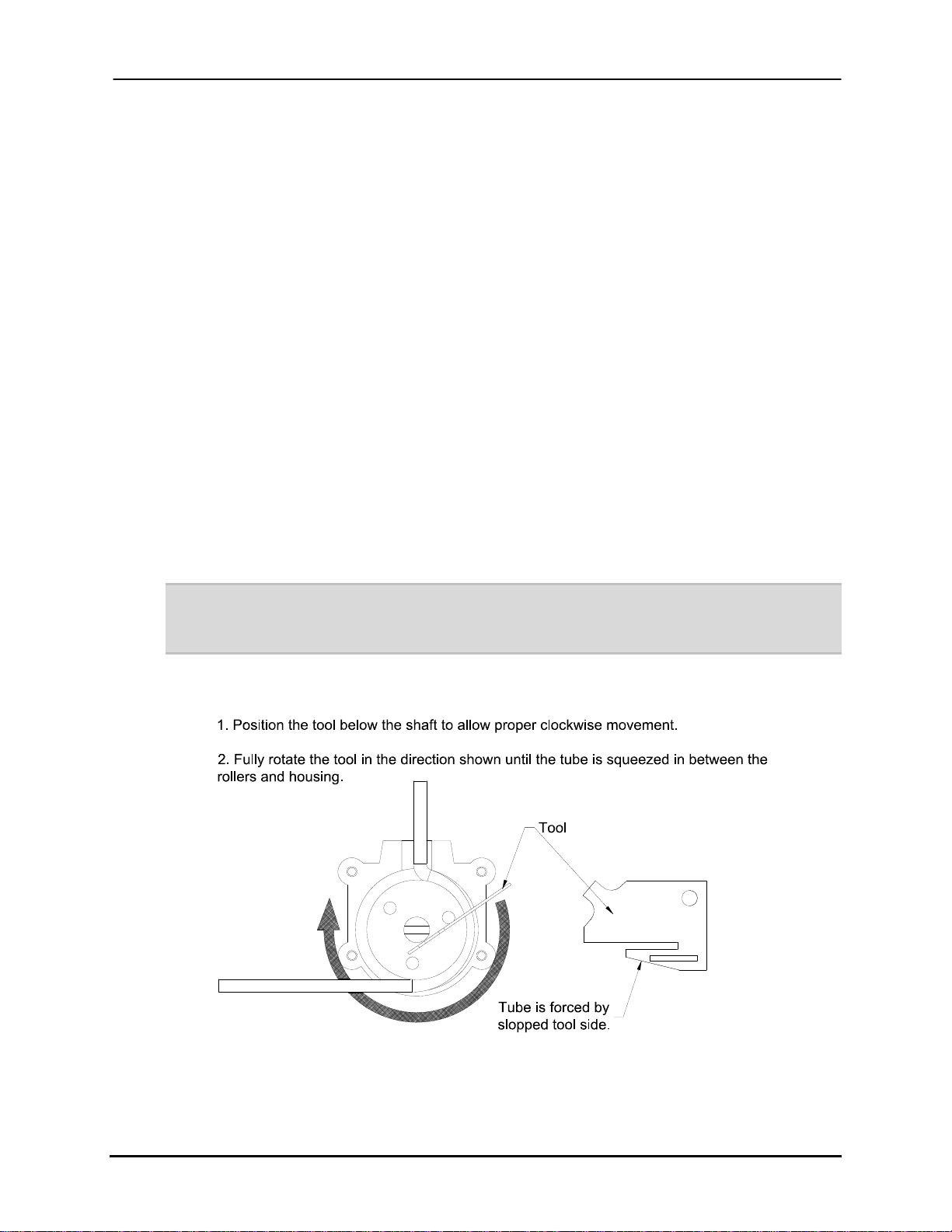
5. Replace the tubing in the peristaltic pump using the tool provided (Figure 2-6).
6. Ensure all lines are connected properly and are tie-wrapped on all fittings to prevent
ink leakage.
Note: It may be necessary to replace the tubing more frequently than specified above
(especially in the peristaltic pump). This should be determined by regularly inspecting the
tubing for signs of wear.
Figure 2-6: Installing Tubing in the Peristaltic Pump
Buskro Ltd. BK705 Ezejet Controller
Page 19

Chapter 2 Controller Components Page 2-8
2.1.7 Replacing the Ink Bottle
Once the ink bottle is empty and the ink level in the subcontainer drops, an ink low icon will
appear (Figure 2-7). At this time, a fresh bottle of ink should be installed.
Figure 2-7: Ink Low Alarm
Note: Ink must NOT be recycled by placing used ink back into the bottle. Not only can this
damage the printhead, but it may also contaminate the filter and result in the ink line
bursting due to backpressure.
Never use unapproved fluids with the system (including other inks) as this could cause
permanent damage to the system. For example, mixing Monet and Cezanne inks will
cause permanent damage to the system. Buskro is not responsible for any damage
caused by improper use.
2.1.8 Peristaltic Pump Head
The peristaltic pump head is responsible for pumping ink from the subcontainer to the
printhead. The number of strokes is controlled electronically by the proximity sensor
installed above the pump head and the gearmotor installed over the metal coupling. The
peristaltic pump head displaces a certain amount of ink per stroke. The arrows show the
direction of the ink pumping (Figure 2-8). The 12 VDC gearmotor drives the pump in a
counter-clockwise direction.
Buskro Ltd. BK705 Ezejet Controller
Page 20

Chapter 2 Controller Components Page 2-9
Figure 2-8: Peristaltic Pump Head
Proximity Sensor
ª
ª
Å
Å
Gearmotor
¨
ª
ª
Note: Tubing must be installed properly as shown to prevent ink from pumping backwards.
ª
Buskro Ltd. BK705 Ezejet Controller
Page 21
Chapter 2 Controller Components Page 2-10
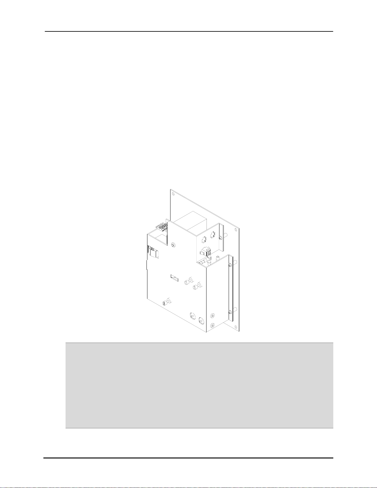
2.1.9 Pressure Regulator
The pressure regulator controls the meniscus vacuum and the purge pressure. The meniscus
vacuum is responsible for maintaining a continuous negative pressure (-3.3 in Wg for 1250
printheads and –4.7 for 2250 printheads) required to prevent ink “weeping” (leaking out of
the head) and for creating a positive purge pressure (50 in Wg) to prime the printheads. The
pressure regulator generates the positive and negative pressures. In order to prevent ink from
being drawn into the pressure regulator, a hydrophobic filter is installed for each printbar to
stop ink from passing through. This filter is also used to filter air used when purging the
printhead. If ink enters the filter, it must be replaced.
Figure 2-9: Pressure Regulator (BK-PVM-700)
Note: If the meniscus pressure is too high, it can prevent proper firing of the jet. Air can also be
ingested into the ink causing jetouts. If the meniscus pressure is too low, ink can leak out
of the head and pool on the orifice plate, material or the transport base. It can also cause
misfires or jetouts.
If the purge pressure is too low, it may be ineffective in recovering jets. If the purge
pressure is too high, it will use more ink. It will also take longer to remove gas from the
ink which could result in jetouts.
If ink leaks from the printhead while the system is powered off, there is likely a leak in the
meniscus line or the solenoid is not closing properly.
Buskro Ltd. BK705 Ezejet Controller
Page 22
Chapter 2 Controller Components Page 2-11
2.2 Apollo Ink Delivery Module (IDM)
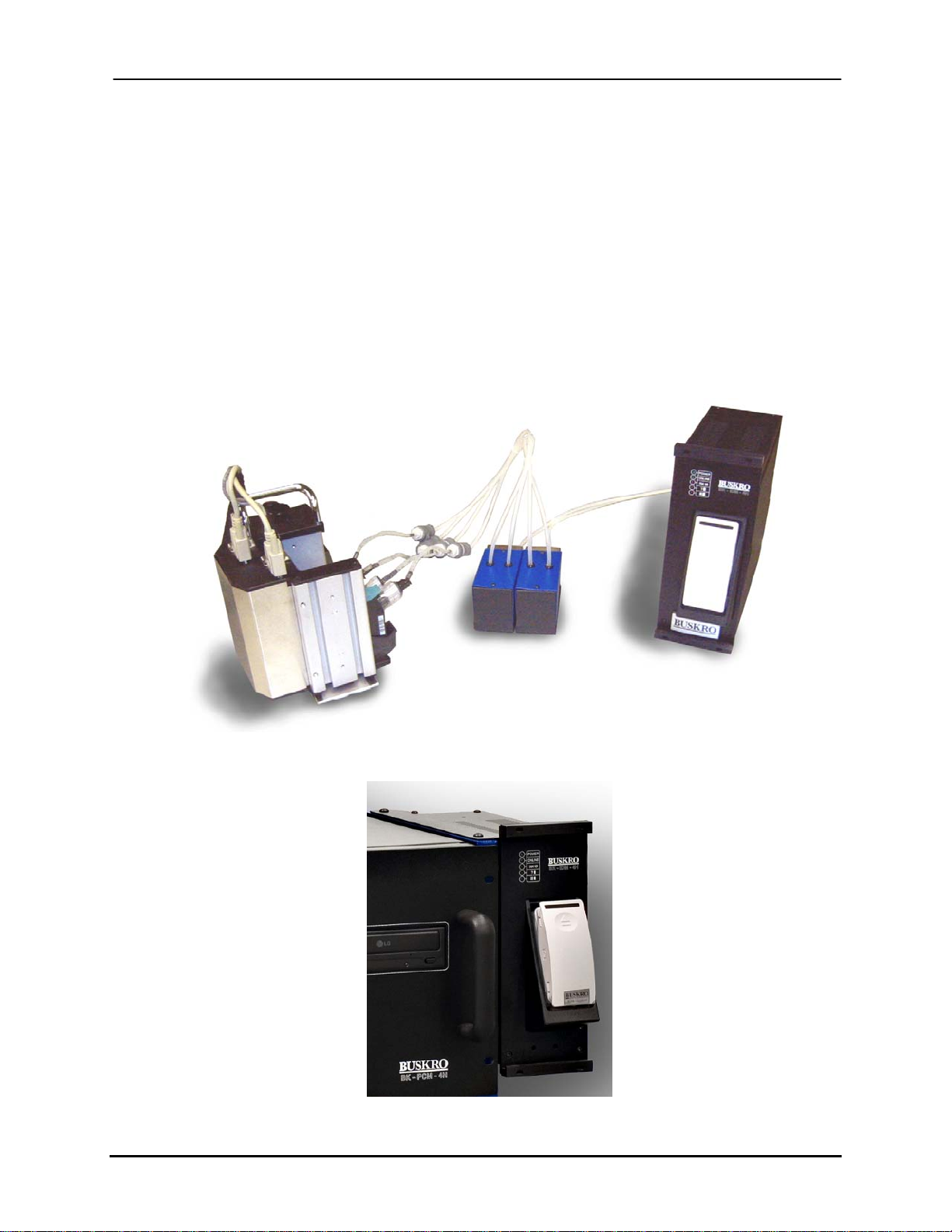
The optional Apollo IDM (Figure 2-10 and Figure 2-11) provides a higher capacity ink
supply for Buskro Apollo printheads. Without the IDM, the user is relying on individual ink
pens that only hold approximately 42 mL of ink each. By using the Ink Delivery Module, the
user is provided with a 350 mL supply which can supply up to eight ink pens simultaneously
(four inches of vertical print swath). The two available kits are 705-IDM4H-15NA (for
North America) and 705-IDM4H-15WD (outside of North America).
Figure 2-10: Apollo Ink Delivery Module
Figure 2-11: Apollo Ink Delivery Module on a BK705
Buskro Ltd. BK705 Ezejet Controller
Page 23

Chapter 2 Controller Components Page 2-12
Some advantages of using the Apollo Ink Delivery Module are:
1. Convenient Ink Management – The ink is distributed and pumped, both vertically
and horizontally, over a maximum of 15’ distance from an operator-accessible point
to all remotely located ink pens.
2. On-the-Fly Refill and Level Sensing – The replaceable 350 mL ink cartridge is
equipped with level sensing that alerts the operator when ink is low. This prompts
the user to replace the ink cartridge.
3. Common Ink Distribution – The Ink Delivery Module features a common manifold
that distributes ink to up to eight ink pens (the pens are the HP 45A “cartridges” in
the printhead). This ensures uniform ink filling to all pens which can reduce
individual failure. For example, if the user relies on individual ink pens, if one pen
runs out of ink before another (e.g. one pen might be printing a heavier part of the
layout), it may result in wasted pieces due to failed printing. When an Ink Delivery
Module is used, all pens are supplied by a single source to avoid this problem.
4. Reduced Intervention – The large 350 mL supply reduces operator intervention
during operation.
5. Front Panel Indicators – The Ink Delivery Module features a series of five indicator
LEDs. These LEDs indicate whether or not there is Power, if the system is Online
and ready to print, if ink is low, if ink is out, or if there is an error.
For more information on the Apollo Ink Delivery Module, refer to the BK-IDM-4H manual
or contact a Buskro representative.
Buskro Ltd. BK705 Ezejet Controller
Page 24
Chapter 2 Controller Components Page 2-13
2.3 Power Supply Module
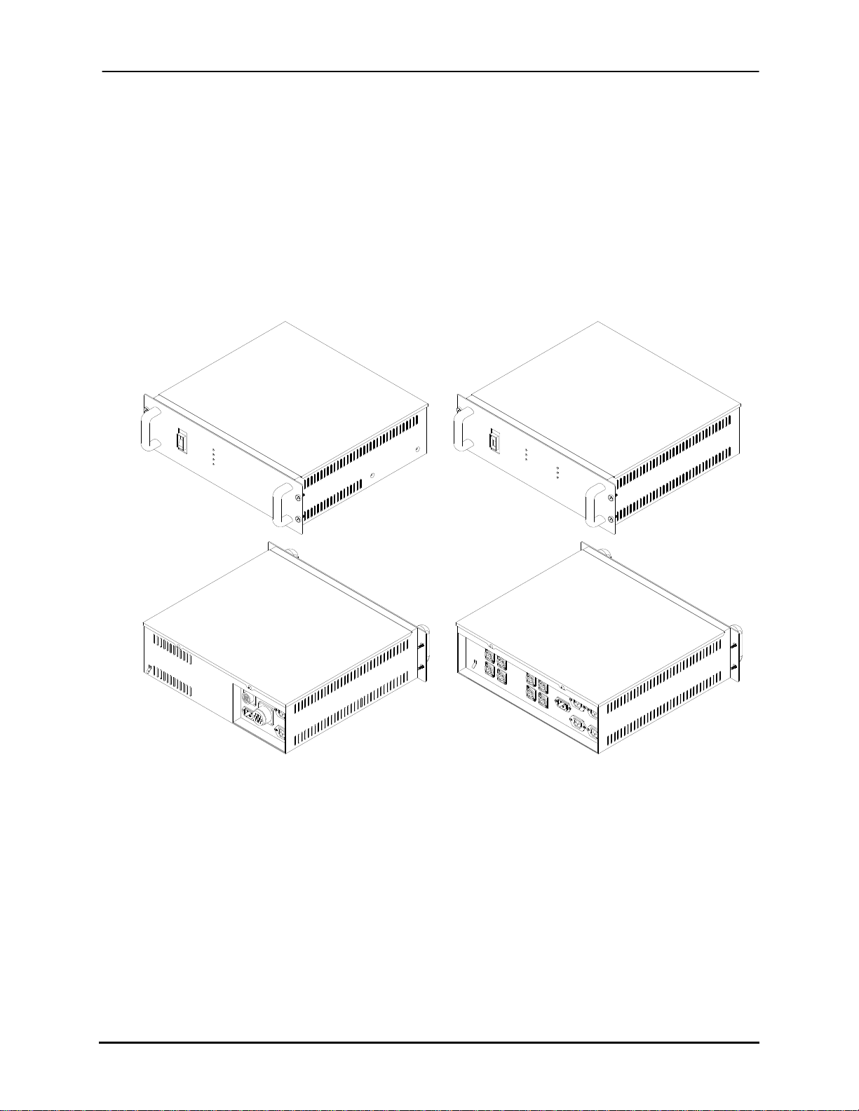
The Power Supply Module (Figure 2-12) is a rack-mounted module that provides the
necessary power requirements for a given technology. Apollo uses the BK-PSM-4H while
Atlas and Aurora (Monet, Cezanne, and Renoir inks) use the BK-PSM-4A.
Figure 2-12: Power Supply Modules (PSM)
BK-PSM-4A
Atlas/Aurora PSM
Front and Back
BK-PSM-4H / BK-PSM-8H
Apollo PSM
Front and Back
Buskro Ltd. BK705 Ezejet Controller
Page 25

Chapter 2 Controller Components Page 2-14
2.4 Field Connection Board
The Field Connection Board (FCB) serves as an interface and electrical isolation between the
controller’s internal circuitry and external equipment. The FCB has a number of inputs and
outputs. The inputs mainly deal with sensor signals (jam detectors, photo sensors, a shaft
encoder, and a cycle input) that are brought out on individual connectors on the connector
panel associated with the FCB. They are also available as a group on a single input cable
connector. The outputs are also brought out on a cable connector and provide relay contact
outputs for such functions as a stop signal to the inkjet equipment, control of a stack function
(to control the speed of a conveyor for stacking purposes), and a diverter.
When the Buskro controller is used with a standard Buskro base, all communications with
the base are internal through a ribbon cable and the connections on FCB are not needed.
The external connections provide a more general interface to allow the controller to work
with a variety of equipment that does not necessarily conform to Buskro’s standards. The
actual operation and connections to the board are discussed in detail in Appendix E.
Buskro Ltd. BK705 Ezejet Controller
Page 26
Chapter 2 Controller Components Page 2-15
2.5 Datapath and Image Accelerator Card
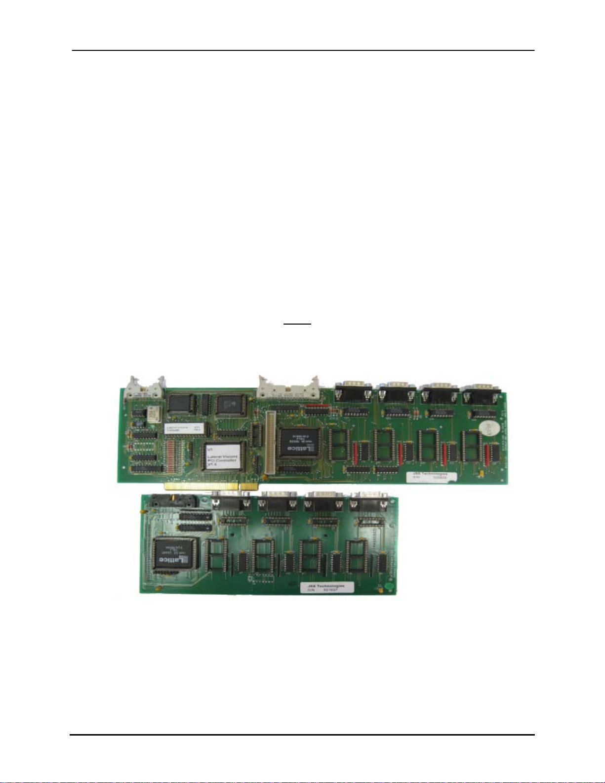
The Datapath (Figure 2-13) and the Image Accelerator (Figure 2-14) Cards connect to the
motherboard through the PCI Bus and perform the following functions:
• When a Buskro transport base is present, interfaces with the Base Interface board or Base
control board to receive sensor inputs from the base.
• Where a Buskro transport base is present, interfaces with the Base Interface board or Base
control board to control the base and conveyor.
• Provides a communication port for control and monitoring of the “life” support elements.
• Receives configuration information from Compose IQ.
• Transmits status information to Compose IQ, the inkjet control software.
• Controls printhead firing sequence.
• Transfers image data via the data ports.
Each Buskro controller is equipped with either a Datapath or Image Accelerator Card.
Figure 2-13: Datapath Card with Expansion Board
The Datapath Card supports four data connections for printheads. An expansion board is
required to add support for an additional four data connections (for a maximum of eight
printheads).
Buskro Ltd. BK705 Ezejet Controller
Page 27
Chapter 2 Controller Components Page 2-16
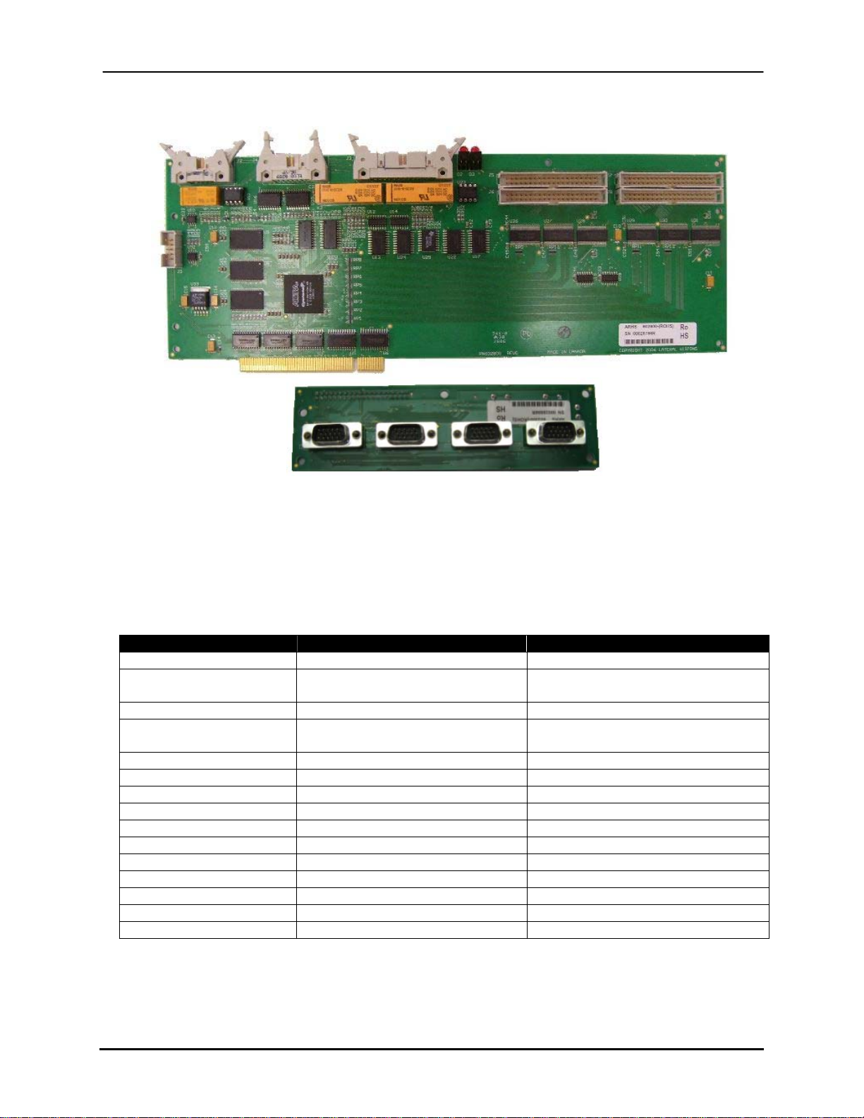
Figure 2-14: Image Accelerator Card with HeadIF Board
The Image Accelerator Card is a replacement for the Datapath card. It is a newer, faster card
with more features. For an overview summary of the differences between the Datapath and
Image Accelerator Cards, reference Table 2-3.
Table 2-3: Datapath and Image Accelerator Card Comparison
Datapath Image Accelerator
Release Date 1997 2008
RoHS Compliant
(Environmental Standard)
Bus Standard PCI PCI
Compatible with newer
motherboards?
License Method Lock Chip or Dongle Dongle
Expansion Hardware Expansion Board HeadIF Card
Firmware EPROM (Hardware Updates) Flash Memory (Software Updates)
Compose Version V8.00 or Earlier V8.01 or Higher
Maximum Data Ports 8 16
Data Transfer Partial Streaming Full Streaming
Tracking Resolution 1” ¼”
Self Diagnostics No Yes
Double Data Rate No Yes
Input Protection Not opto-isolated Opto-isolated
Hyperion Support No Yes
No Yes
No Yes
Buskro Ltd. BK705 Ezejet Controller
Page 28
Chapter 2 Controller Components Page 2-17
2.5.1 Image Accelerator Card Diagnostics
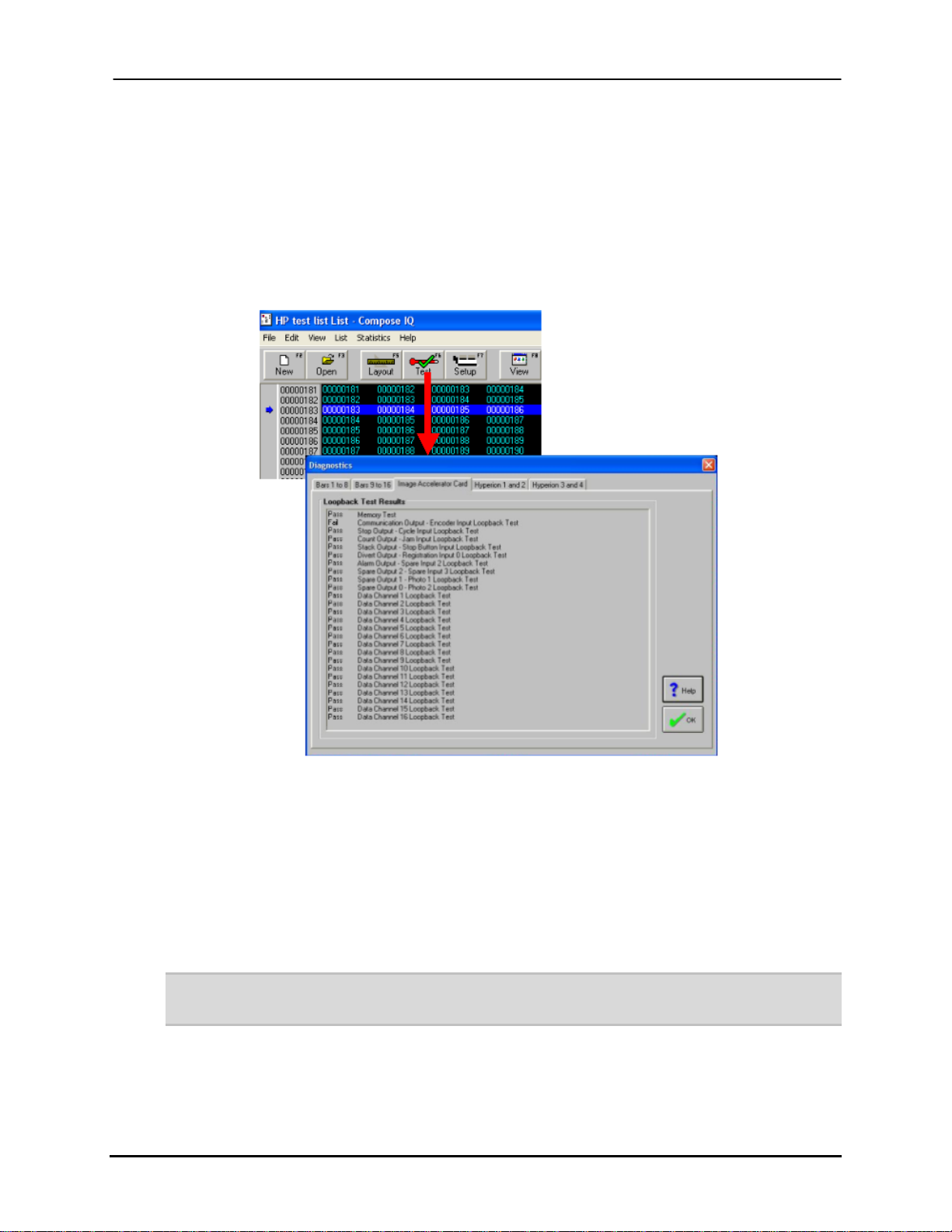
The Image Accelerator Card has the ability to diagnose itself to assist with troubleshooting.
It is able to test its internal memory, all inputs and outputs, and all the data channels (print
ports). This can be accessed through the Test / Diagnostics screen (Figure 2-15).
Figure 2-15: Image Accelerator Card Diagnostics
2.5.2 Firmware Updates
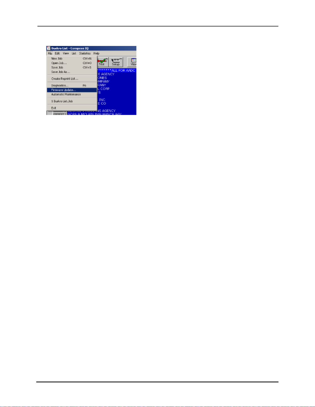
With Buskro’s new line of electronics (Image Accelerator Card, HP Interface Board II, and
SSB CPU II), firmware updates can be made directly through Compose (Figure 2-16). This
simplifies the upgrade process by eliminating the need to replace a hardware EPROM for
each firmware change.
Note: NEVER interrupt a Firmware update. If the update does not complete successfully, retry
the update.
Buskro Ltd. BK705 Ezejet Controller
Page 29
Chapter 2 Controller Components Page 2-18
Figure 2-16: Firmware Update
The firmware update procedure is as follows:
1. Choose “File” then “Firmware Update”. The current firmware version is displayed
in the dialog box. The “Update” button is only enabled for existent boards.
2. To update the Image Accelerator Card, press the “Update” button beside
“Accelerator FPGA”. The update takes approximately 30 seconds to complete. The
update progress is displayed in the progress bar.
3. Before updating an HP Interface Board II or SSB CPU II, power down the system
and set the Program DIP Switch on the respective board (position 8) to ON. Then
reboot the system.
4. To update the HP Interface Board II or SSB CPU II, press the update button. The
update takes approximately 4 minutes to complete. The update progress is displayed
in the progress bar.
5. After updating an HP Interface Board II or SSB CPU II, power down the system and
set the Program DIP Switch on the respective board (position 8) to OFF. Then reboot
the system.
6. If the Compose Release notes indicate that the CPLD on the board requires updating,
power down the system and set the CPLD Program DIP Switch (position 7) to ON
and the Program DIP Switch (position 8) to OFF before rebooting the system. The
RUN LED will blink rapidly to indicate the CPLD programming progress, after
which the RUN LED will resume its normal (1 second on, 1 second off) blink rate.
7. After updating the CPLD, power down the system and set the CPLD Program DIP
switch (position 7) OFF. Then reboot the system.
Buskro Ltd. BK705 Ezejet Controller
Page 30

Chapter 2 Controller Components Page 2-19
2.6 Optional Hardware
2.6.1 Serial Card (P/N BK-COMM)
The Serial Card is a “smart” high-speed serial communications card equipped with its own
processor. It is designed to plug into a PCI slot on the computer motherboard and has 4
connectors for serial communications cables. These connectors are standard RS-232
connectors in a DB-25 configuration and use a null modem. More information can be
found in the Appendix.
2.6.2 Expansion Board (P/N BK-EXP-1700)
The Expansion Board is only used with the Datapath Card. It is used to add the capacity
for four more data ports (for up to four more printheads), allows for a second technology
to be added, and provides access to use the Tracking Board.
2.6.3 Image Accelerator Expansion Module (P/N BK-EXP-IAC)
The Expansion Module is used to add the capacity for an additional four data ports for
systems utilizing the Image Accelerator Board. This kit is not required to add multiple
technologies or to access the Tracking Board as these features are inherent in the Image
Accelerator Card. To activate these features, the appropriate license option is required
(BKLI-OPT-CBO for multiple technologies and BKLI-OPT-TRK for Tracking).
2.6.4 Tracking Board (P/N BK-TRACK-1700)
By purchasing the Tracking option for the BK705, this provides users with the ability to
track each product as it travels through the system which is comprised of a series of zones
(e.g. inkjet zone, inserter zone, etc). It is also possible to track products through nonBuskro equipment. For more information, contact a Buskro representative.
Buskro Ltd. BK705 Ezejet Controller
Page 31
Chapter 2 Controller Components Page 2-20
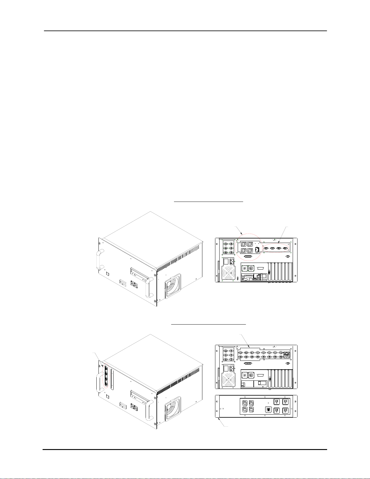
For Atlas or Aurora systems, the tracking board can be ordered (BK-TRACK-1700). For
Apollo systems, the tracking controller (P/N BK705-TR) should be ordered instead of the
standard controller (P/N BK705). Since a tracking board assembly is required (P/N BKTRACK-1700), a slightly different computer assembly is needed. Instead of using the
integrated Apollo power supply found in the computer assembly of the standard Apollo
BK705, a separate power supply (P/N BK-PSM-4H) is used. In addition, the computer
module faceplate changes to support data connections in the front instead of the back. In
this configuration, the computer assembly is the same as the one used in the BK1705,
BK1710, and BK1720 controllers. Figure 2-17 provides a visual representation of the
differences.
Figure 2-17: Computer Assemblies with and without Tracking
BK-PCM-4H (For BK705)
Data Connections
Apollo Power Supply
BK-PCM-8 (For BK705-TR)
Tracking Assembly
Data Connections
Separate Apollo Power Supply (BK-PSM-4H)
Buskro Ltd. BK705 Ezejet Controller
Page 32
Chapter 2 Controller Components Page 2-21
2.7 Grounding
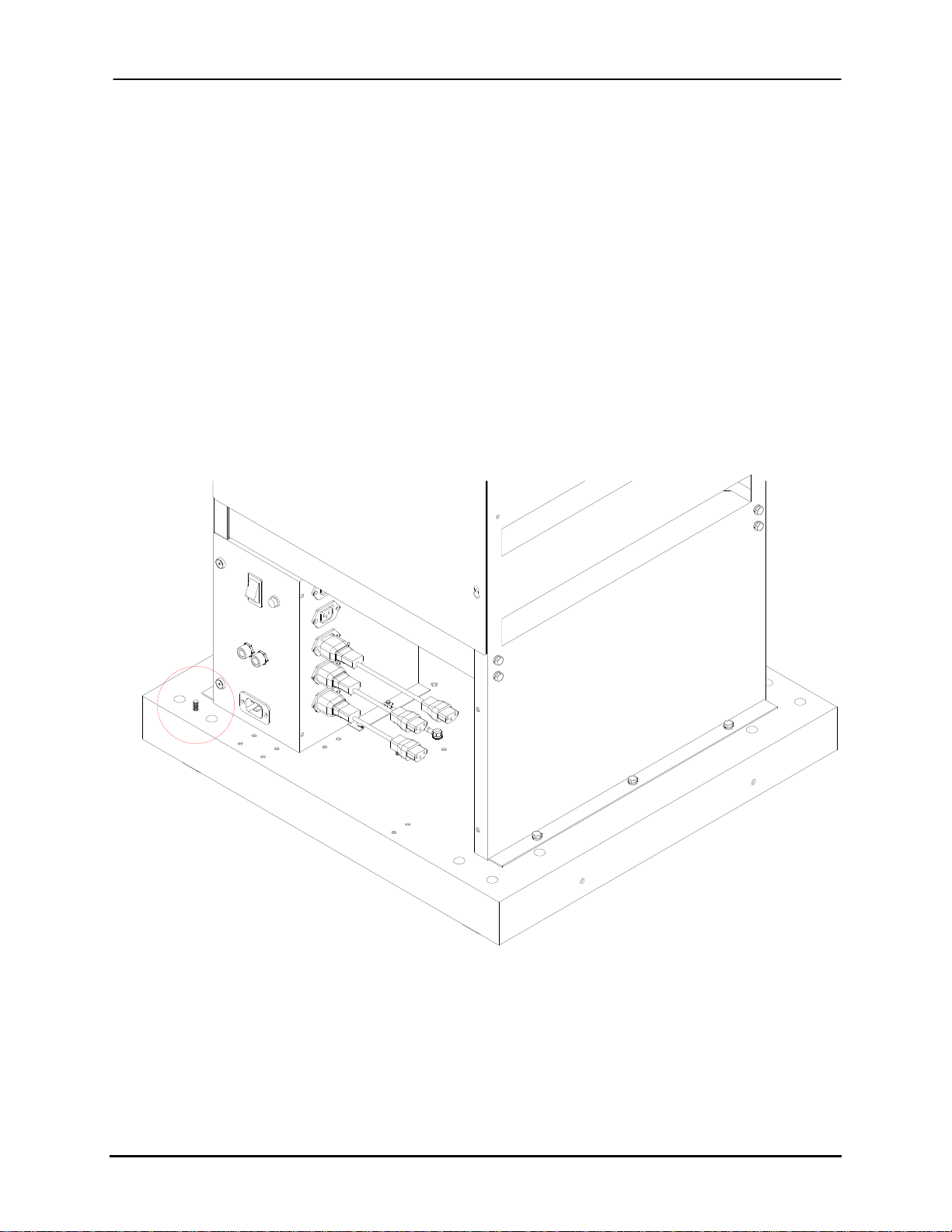
Proper grounding is essential for proper operation of equipment as well as for safety. If a
system is improperly grounded, it can result in an array of intermittent or even permanent
operational problems. In the case of the BK705 Controller stand, each individual panel is
connected together with a common ground using ground wires. The individual modules
also need to be grounded to the stand (e.g. computer or power supply modules) through
the available ground tabs or studs. It is also important to ground the controller to the
transport base. A ground stud on the stand is available to connect a ground wire to other
equipment in the system (Figure 2-18).
Figure 2-18: BK705 Ground Stud
Buskro Ltd. BK705 Ezejet Controller
Page 33
Chapter 2 Controller Components Page 2-22
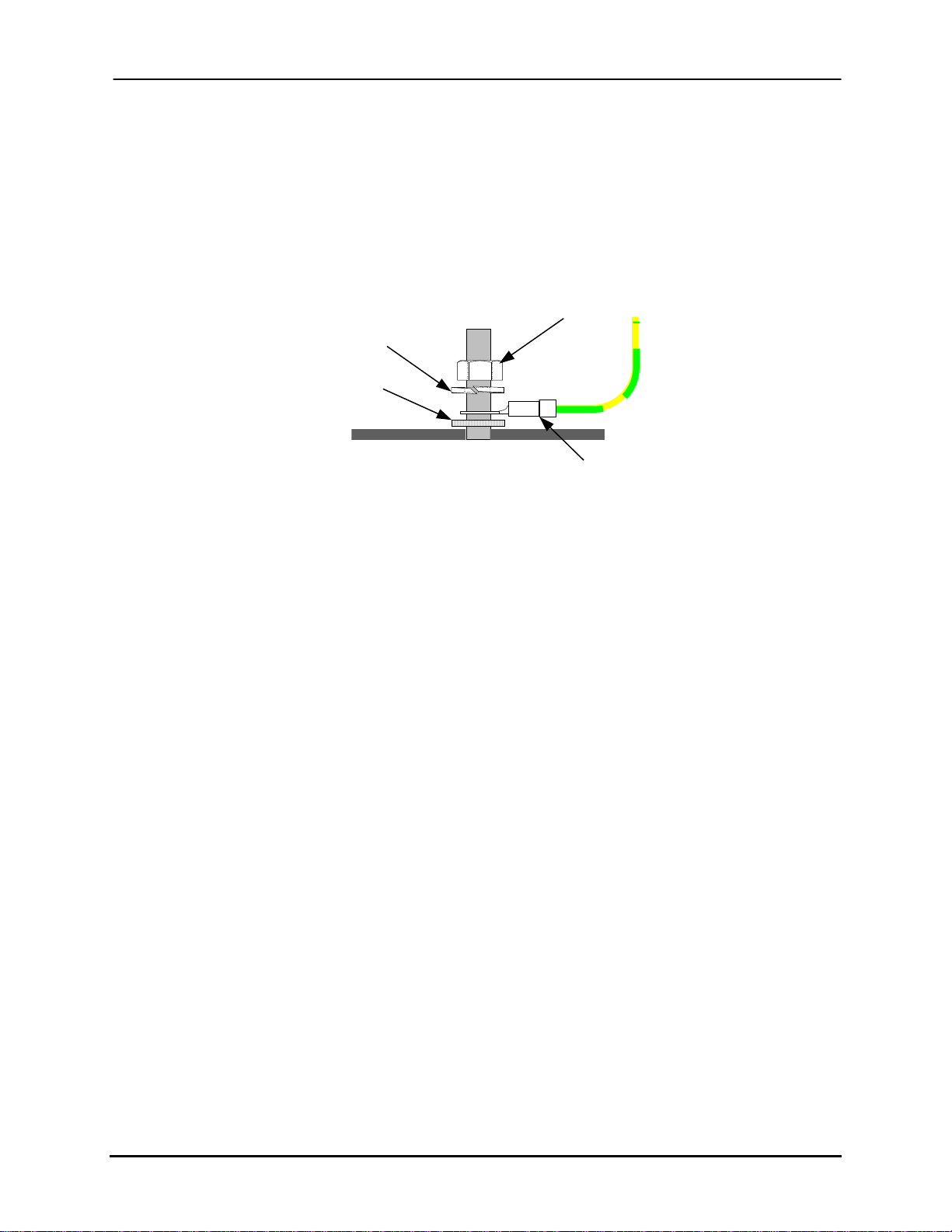
When connecting to a ground stud, it is important to use a star lockwasher to cut into the
finish of the cabinet (Figure 2-19). This is because paint or finishes can act as an
insulator. It is recommended to use an AWG 12 or heavier green/yellow wire when
connecting the ground between machines.
Figure 2-19: Ground Stud
Nut, ¼-20 UNC
Lockwasher, ¼"
I.D. (439010)
Star Lockwasher,
¼" I.D. (439007)
(420010)
Ground Connection
Buskro Ltd. BK705 Ezejet Controller
Page 34

Compose IQ
3.0 Compose IQ
Chapter 3
Buskro Ltd. BK705 Ezejet Controller
Page 35
Chapter 3 Compose IQ Page 3-1
3.1 Introduction
In general, Buskro print technology is designed to work with a Buskro controller equipped
with Compose IQ software. Compose IQ is a Windows® based application that controls
all operational aspects of a Buskro inkjet system. This easy-to-use control software
delivers powerful job setup, layout, production management, record control, diagnostics,
and reporting.
Compose IQ is a built-in package capable of supporting systems applications in which
machine control, data acquisition, print sequencing, and product tracking or a combination
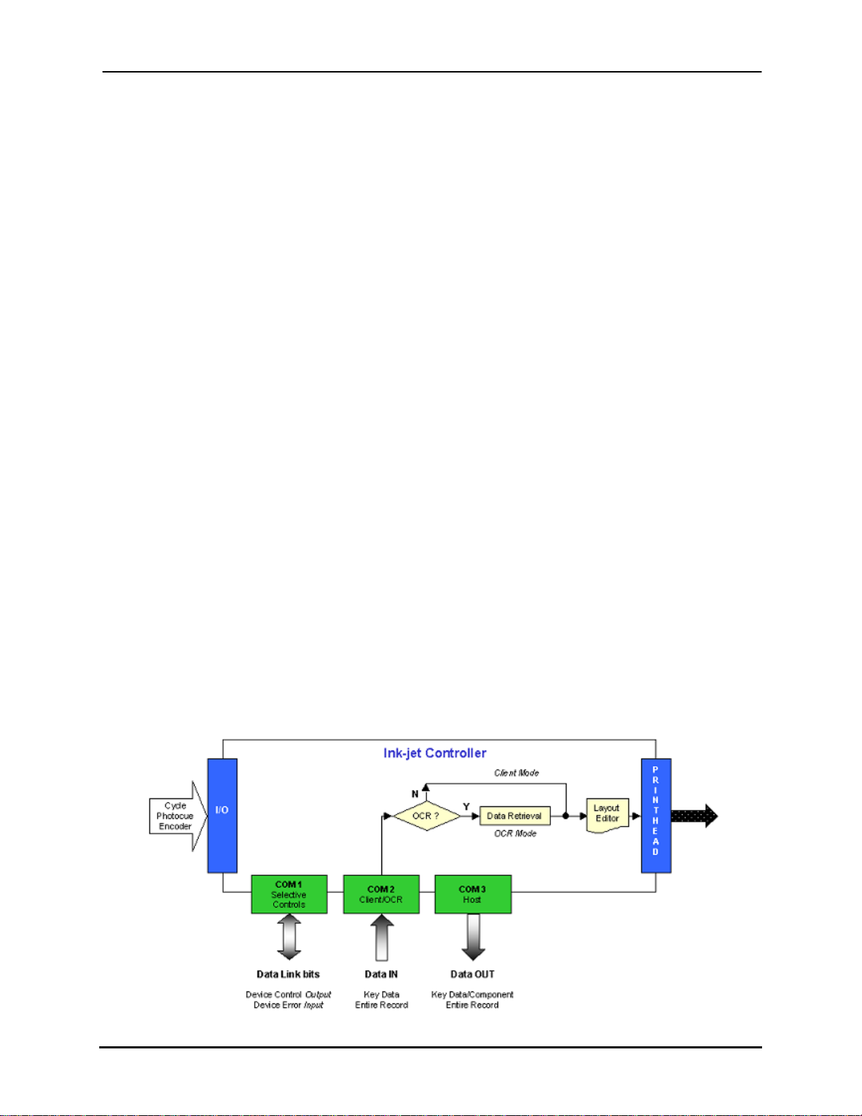
thereof may be required. Essentially, the software provides the following rudimentary
tools:
• Product tracking and print sequencing
• Communication with reading devices or other controllers via the COM2 serial port
• Data output communication with other devices via COM3
• Machine control utilizing a PLC with communication via COM1
• Data acquisition and record retrieval in OCR mode
The software offers three distinct building blocks for the implementation of a system.
This includes client (slave) mode, OCR mode, and selective device control supporting
host mode (master) for data echo requirements. Figure 3-1 below illustrates the different
configurations:
Figure 3-1: Block diagram of various models and the I/O devices required
Buskro Ltd. BK705 Ezejet Controller
Page 36

Chapter 3 Compose IQ Page 3-2
3.2 Host/Client Mode
3.2.1 Client Mode
Client mode permits the controller to accept data directly from another controller (device)
via the serial COM2 port, and at the appropriate time, print out some or all of the data
based on the image layout. A number of baud rates and physical definition tools are
offered to tailor the controller to the physical delays of the system and provide a data
communication link with a host controller (device).
3.2.2 Host Mode
Host mode provides a means whereby a portion or all of the printed record data is output
on COM3 such that it can be acquired and used by a downstream controller/device. This
capability allows for the creation of distributed systems in which a number of printers can
be networked together and controlled by a host controller.
3.3 OCR Mode
The OCR mode functions in much the same way as the client mode with the addition of a
lookup and data retrieval process occurring prior to image creation. This capability
supports reading devices that send limited data via the serial COM2 port, representing a
key that maps onto a defined component of the data file such that a search will find and
retrieve the entire record corresponding to the key. As with the client mode, the resulting
record’s components are then printed out as defined by the image layout.
Buskro Ltd. BK705 Ezejet Controller
Page 37

Chapter 3 Compose IQ Page 3-3
3.4 Selective Inserting Mode
Completing the suite of controller products is a selective device control operation. With
this, individual records are sourced from the aforementioned applications or the resident
database and subsequently queried prior to the printing operation. As a result, various
upstream and downstream devices can be actuated via a PLC based on the contents of
these records. Included with this is a data echo feature that outputs all or part of the
printed record on the COM3 serial port for communication with other downstream client
controllers. This creates a distributed network of printers.
PLC control and communication is enabled through the COM1 port where a number of
virtual input/output points are transmitted and stored directly in the PLC for further
processing. Using this type of system architecture, logical functions are performed by the
generic printer controller with the PLC providing localized system customization to
implement the instructions supplied by the controller.
3.5 Compose IQ Dongle
The Dongle is a serialized device that is installed in one of the USB ports of the controller.
It acts as the license enabling mechanism for users with a Compose Version of 6 or later.
It must have a valid dongle information file encrypted within it to become active. The
correct dongle information file specific to the serial number of the physical dongle and to
the print technology and Compose functionality purchased is required. The Dongle is
field-programmable so that options may be added without swapping Dongles. The Dongle
requires drivers that are loaded with Compose V6.03 or later. In the Compose Help system
the driver installation procedure is listed.
3.6 Compose Software
For more detailed information about Compose IQ, reference the help file included with the
software. Only some of the basic functions are described in this manual.
Buskro Ltd. BK705 Ezejet Controller
Page 38
Chapter 3 Compose IQ Page 3-4
3.6.1 Printhead Drivers
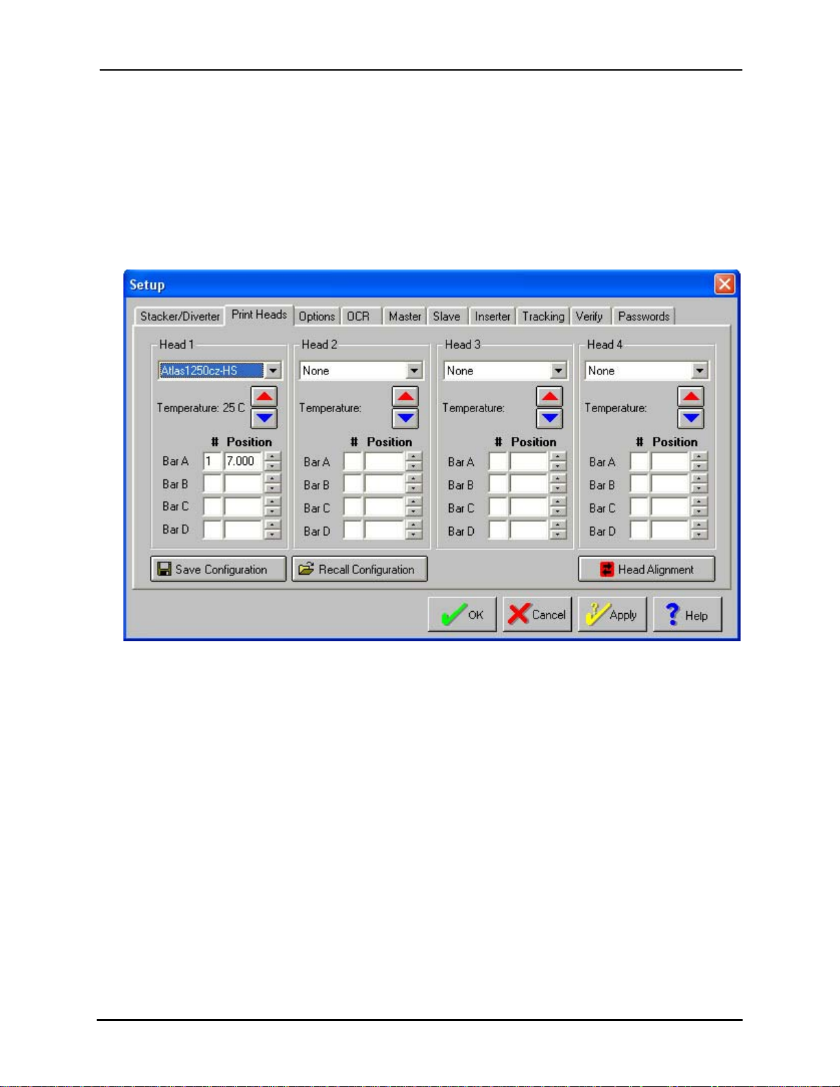
In order to integrate the print technology with Compose, the proper printhead driver must
be specified in the Setup menu as well as its relative distance from the photo sensor
(Figure 3-2).
Figure 3-2: Compose Setup Window
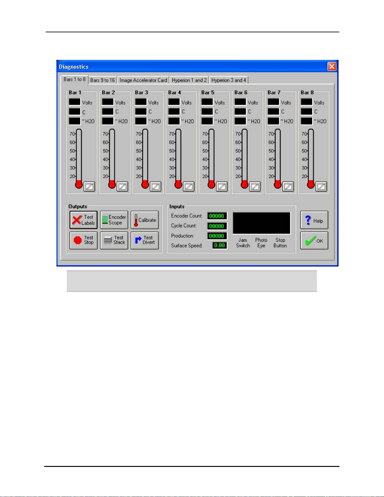
3.6.2 Diagnostics Screen
The Compose diagnostic screen displays the voltage and temperature readings for each
printbar (Figure 3-3). The voltage value can be different for each jetting assembly. As a
result, it is preset before shipment with the factory settings. The normal voltage range for
an Atlas or Aurora printhead is 80-100 volts. The temperature reading depends on the ink
technology used.
Buskro Ltd. BK705 Ezejet Controller
Page 39
Chapter 3 Compose IQ Page 3-5
Figure 3-3: Compose Diagnostics Window
Note: Only trained technicians should make adjustments to the Voltage as it can affect
print performance.
Buskro Ltd. BK705 Ezejet Controller
Page 40

Assembly Drawings
A.0 Assembly Drawings
Appendix A
List of Figures
Figure A-1: BK705 – Apollo Ezejet Controller............................................................. A-1
Figure A-2: BK705-TR – Apollo Ezejet Controller with Tracking............................... A-2
Figure A-3: BK705-ST – BK705 Controller Stand....................................................... A-4
Figure A-4: BK-PCM-4H – Module, Computer, Apollo BK705.................................. A-5
Figure A-5: BK-PCM-8 – Module, Computer Assembly, Universal............................ A-6
Figure A-6: 9102781A – Fan Assembly, 12 VDC......................................................... A-7
Figure A-7: 9103178A – Field Connection Board Assembly, BK-PCM...................... A-8
Figure A-8: 9103219A – Caster Wheel Assembly ........................................................ A-9
Figure A-9: 9104116A – HeadIF Assembly................................................................ A-10
Figure A-10: 9104127A – Computer Drive Mount Assembly.................................... A-11
Figure A-11: 9104130A – Computer PCM Chassis Assembly, Universal.................. A-13
Figure A-12: 9104135A – Image Accelerator Card Assembly, PCM......................... A-14
Figure A-13: 9104194A – Faceplate Assembly, BK-PCM-8...................................... A-15
Figure A-14: 9104415A – Apollo Power Supply Assembly, BK-PCM-4H................ A-16
Figure A-15: 9104423A – Faceplate assembly, BK-PCM-4H.................................... A-17
Figure A-16: 9104466A – Back Cover Assembly....................................................... A-18
Figure A-17: 9104486A – Monitor/Keyboard Stand, BK705 ..................................... A-19
Figure A-18: 9104487A – Telescopic Arm/tray Assembly......................................... A-20
Figure A-19: 9104488A – Stand Assembly................................................................. A-21
Figure A-20: 9104912A - Power Distribution Box Assembly, BK705....................... A-23
Figure A-21: 9104913A – Cover Assembly, BK705................................................... A-24
Buskro Ltd. BK705
Page 41

Appendix A Assembly Drawings
List of Tables
Table A-1: BK705 – Apollo Ezejet Controller.............................................................. A-1
Table A-2: BK705-TR – Apollo Ezejet Controller with Tracking................................ A-2
Table A-3: BK705-ST – BK705 Controller Stand ........................................................ A-3
Table A-4: BK-PCM-4H – Module, Computer, Apollo BK705 ................................... A-5
Table A-5: BK-PCM-8 – Module, Computer Assembly, Universal ............................. A-6
Table A-6: 9102781A – Fan Assembly, 12 VDC.......................................................... A-7
Table A-7: 9103178A – Field Connection Board Assembly, BK-PCM ....................... A-8
Table A-8: 9103219A – Caster Wheel Assembly ......................................................... A-9
Table A-9: 9104116A – HeadIF Assembly................................................................. A-10
Table A-10: 9104127A – Computer Drive Mount Assembly ..................................... A-11
Table A-11: 9104130A – Computer PCM Chassis Assembly, Universal................... A-12
Table A-12: 9104135A – Image Accelerator Card Assembly, PCM.......................... A-14
Table A-13: 9104194A – Faceplate Assembly, BK-PCM-8....................................... A-15
Table A-14: 9104415A – Apollo Power Supply Assembly, BK-PCM-4H................. A-16
Table A-15: 9104423A – Faceplate assembly, BK-PCM-4H ..................................... A-17
Table A-16: 9104466A – Back Cover Assembly........................................................ A-18
Table A-17: 9104486A – Monitor/Keyboard Stand, BK705 ...................................... A-19
Table A-18: 9104487A – Telescopic Arm/tray Assembly.......................................... A-20
Table A-19: 9104488A – Stand Assembly.................................................................. A-21
Table A-20: 9104912A – Power Distribution Box Assembly, BK705 ....................... A-22
Table A-21: 9104913A – Cover Assembly, BK705.................................................... A-24
Buskro Ltd. BK705
Page 42
Appendix A Assembly Drawings
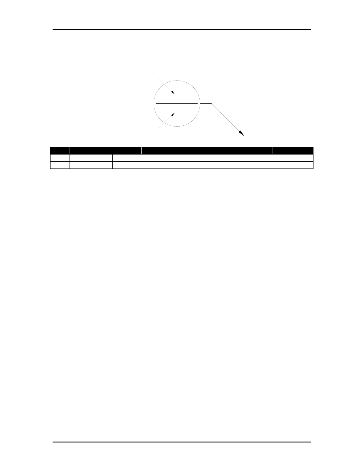
Balloon Annotation and Parts Listing
Item Number
5
8
Quantity
Item Part Number Quantity Description Reference
1
2
The following is a description of how to interpret the information in this section:
Item:
This column indicates the item number used for each unique part in an assembly drawing.
It is matched with the top number in the balloon pointing at the associated part.
Part Number:
This column represents the Buskro part number.
Quantity:
This represents the total number of a given part in an assembly. It is matched with the
bottom number in the balloon pointing at the associated part.
Description:
This column contains a brief description of the part.
Reference:
This column indicates the page location for sub-assemblies.
Buskro Ltd. BK705
Page 43
Appendix A Assembly Drawings Page A-1
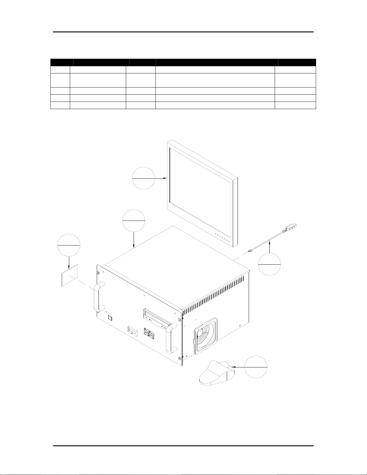
Table A-1: BK705 – Apollo Ezejet Controller
Item Part Number Quantity Description Reference
1 9101627 1 Buskro Serial Number Label
2 9103134A 1 Kit, Accessory, BK705 (Includes
Trackball)
3 9103285A 1 Dongle Assembly
4 BK-MON-LCD17 1 Monitor. 17" LCD display
5 BK-PCM-4H 1 Module, Computer, Apollo BK705 Page A-5
Figure A-1: BK705 – Apollo Ezejet Controller
4
1
5
1
1
1
3
1
2
1
Buskro Ltd. BK705
Page 44
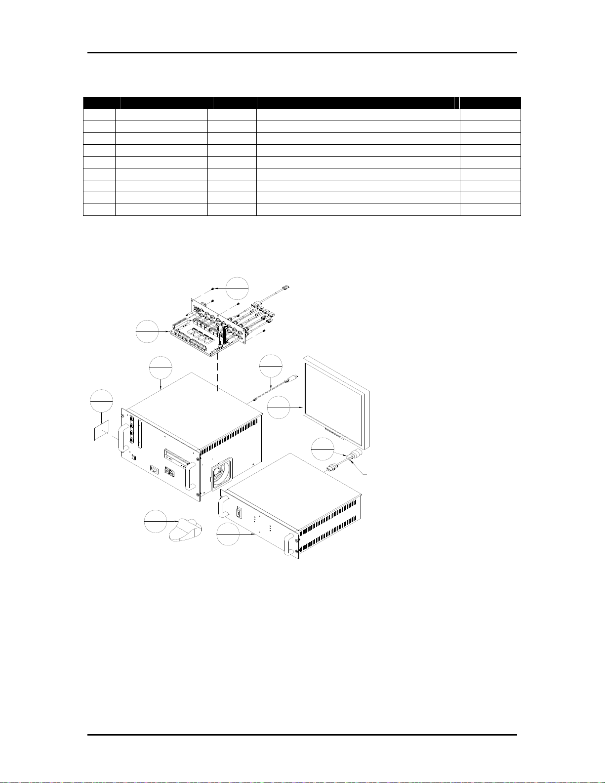
Appendix A Assembly Drawings Page A-2
Table A-2: BK705-TR – Apollo Ezejet Controller with Tracking
Item Part Number Quantity Description Reference
1 404520 6 Screw, BHCS, 10-32 UNF x 3/8"
2 9101627 1 Buskro Serial Number Label
3 9103134A 1 Kit, Accessory, BK705 (Includes Trackball)
4 9103285A 1 Dongle Assembly
5 9104512 1 Cord, Set, 10A/250V, 1m, Harmonized, IEC
6 BK-MON-LCD17 1 Monitor. 17" LCD display
7 BK-PCM-8 1 Computer PCM Chassis Assembly Page A-6
8 BK-PSM-4H 1 Module, Apollo Power Supply, 4 Channel
9 BK-TRACK-1700 1 Tracking Board Assembly, BK-PCM
Figure A-2: BK705-TR – Apollo Ezejet Controller with Tracking
1
6
9
1
7
1
2
1
3
1
8
1
4
1
6
1
5
1
USE 9104512 WITH BK705-ST STAND.
USE 606322 IF NO STAND IN NORTH AMERICA.
Buskro Ltd. BK705
Page 45
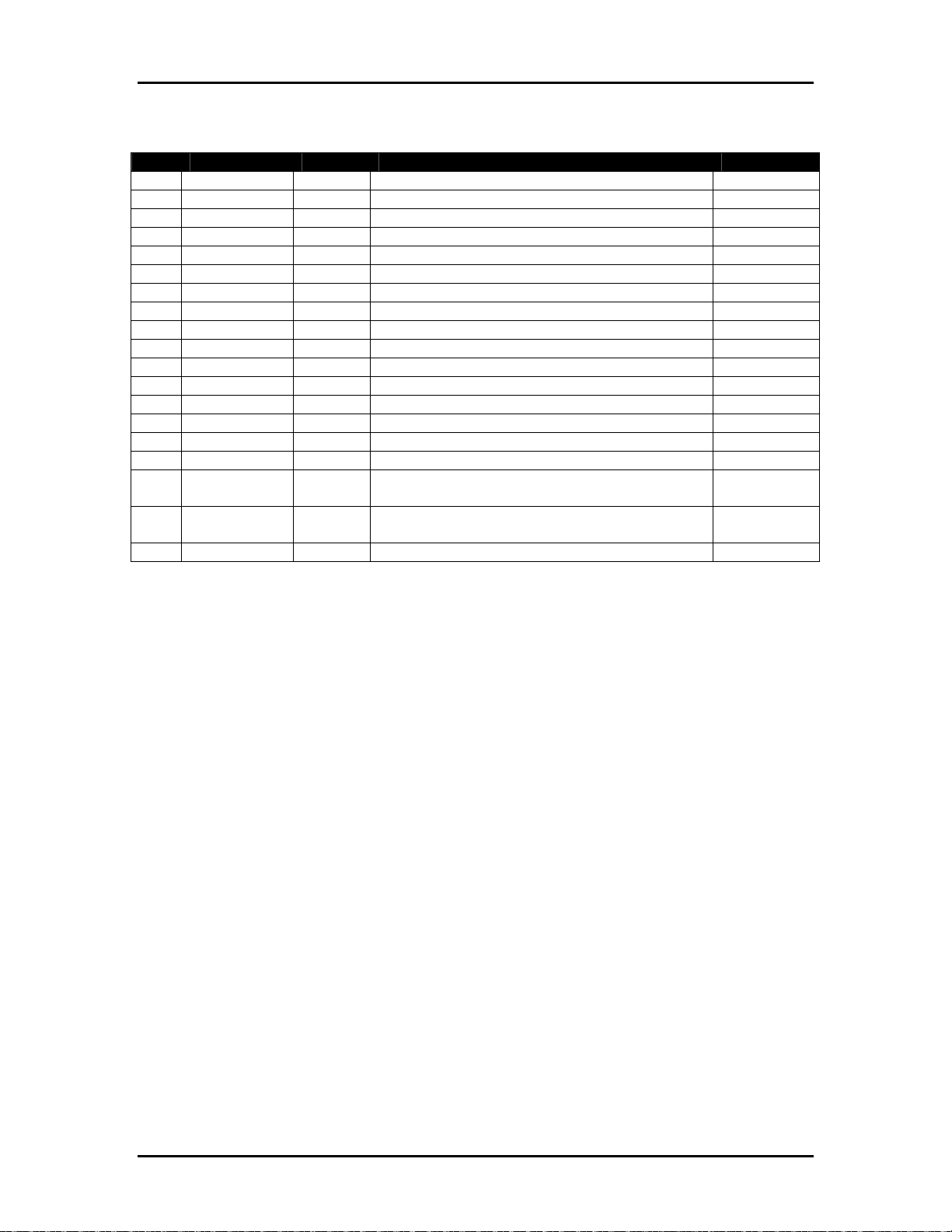
Appendix A Assembly Drawings Page A-3
Table A-3: BK705-ST – BK705 Controller Stand
Item Part Number Quantity Description Reference
1 404050 2 Screw, FHCS, 10-32 UNF x ¾”
2 404520 5 Screw, BHCS, 10-32 UNF x 3/8"
3 405530 2 Screw, BHCS, ¼-20 UNC x ½”
4 405650 18 Screw, HHMS, 1/4-20 UNC X 3/4”
5 439010 18 Lockwasher, 1/4 in I.D.
6 440010 18 Washer, 1/4 in ID
7 609110 8 Connector, Push-on, 16-14 AWG, Blue
8 9102068 16 Bolt, Carriage, 1/4-20 UNC, 3/4" LG.
9 9102681 4 Wire #14, Green/Yellow hookup, 3" Lg.
10 9103219A 4 Caster Wheel Assembly Page A-9
11 9103315 2 Washer, Cup, 10-32 UNF Flat Head Screw
12 9104462 1 Platform, LC Apollo
13 9104463 2 Side Bracket, BK705
14 9104465 2 Cross Bracket, BK705 Stand
15 9104466A 1 Back Cover Assembly, BK705 Page A-18
16 9104486A 1 Monitor/Keyboard Stand, BK705 Page A-19
17 9104511 1 Cord Set, 10A/250V, 2m, Harmonized, IEC-
IEC
18 9104512 2 Cord Set, 10A/250V, 1m, Harmonized, IEC-
IEC
19 9104912A 1 Power Distribution Box Assembly Page A-22
Buskro Ltd. BK705
Page 46
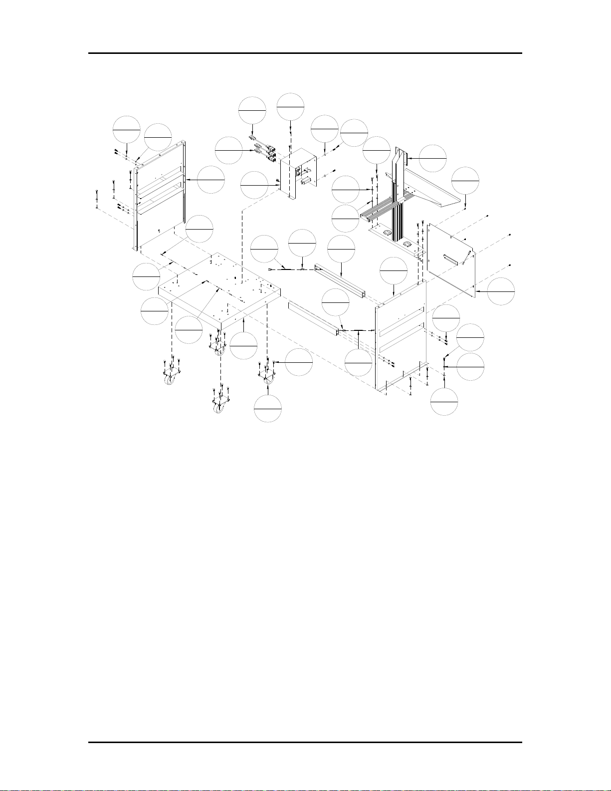
Appendix A Assembly Drawings Page A-4
Figure A-3: BK705-ST – BK705 Controller Stand
17
1
5
18
6
18
9
4
7
8
9
4
18
2
13
2
7
8
19
1
12
1
3
2
11
9
4
7
8
8
16
1
2
2
4
18
5
18
6
18
14
2
13
2
7
8
9
4
16
1
2
5
15
1
4
18
4
18
5
18
10
4
6
18
Buskro Ltd. BK705
Page 47
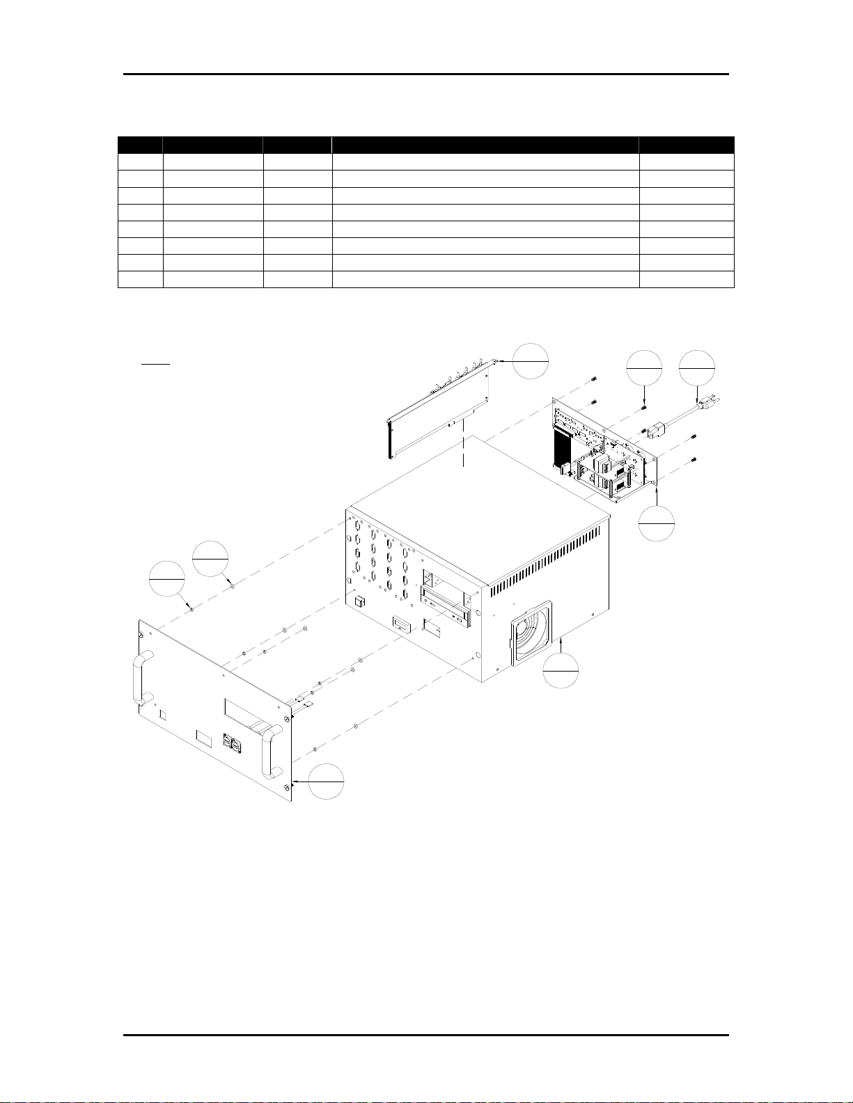
Appendix A Assembly Drawings Page A-5
Table A-4: BK-PCM-4H – Module, Computer, Apollo BK705
Item Part Number Quantity Description Reference
1 404520 6 Screw, BHCS, 10-32 UNF x 3/8”
2 420008 6 Nut, 10-32 UNF
3 439009 6 Lockwasher, No. 10
4 606322 1 Cord, Set, 10A/125VAC, 90”, N.A., IEC
5 9104130A 1 Computer PCM Chassis Assembly, Universal Page A-12
6 9104135A 1 Image Accelerator Card Assembly Page A-14
7 9104415A 1 Power Supply Assembly, BK-PCM-4H, Apollo Page A-16
8 9104423A 1 Faceplate assembly, BK-PCM-4H Page A-17
Figure A-4: BK-PCM-4H – Module, Computer, Apollo BK705
NOTE:
FOR NORTH AMERICA USE POWER CORD 606322.
FOR INTERNATIONAL USE POWER CORD 9103256.
WHEN USED WITH A STAND (BK705-ST) USE POWER
CORDS INCLUDED WITH THE STAND.
2
3
6
6
6
1
5
1
1
6
4
1
7
1
8
1
Buskro Ltd. BK705
Page 48
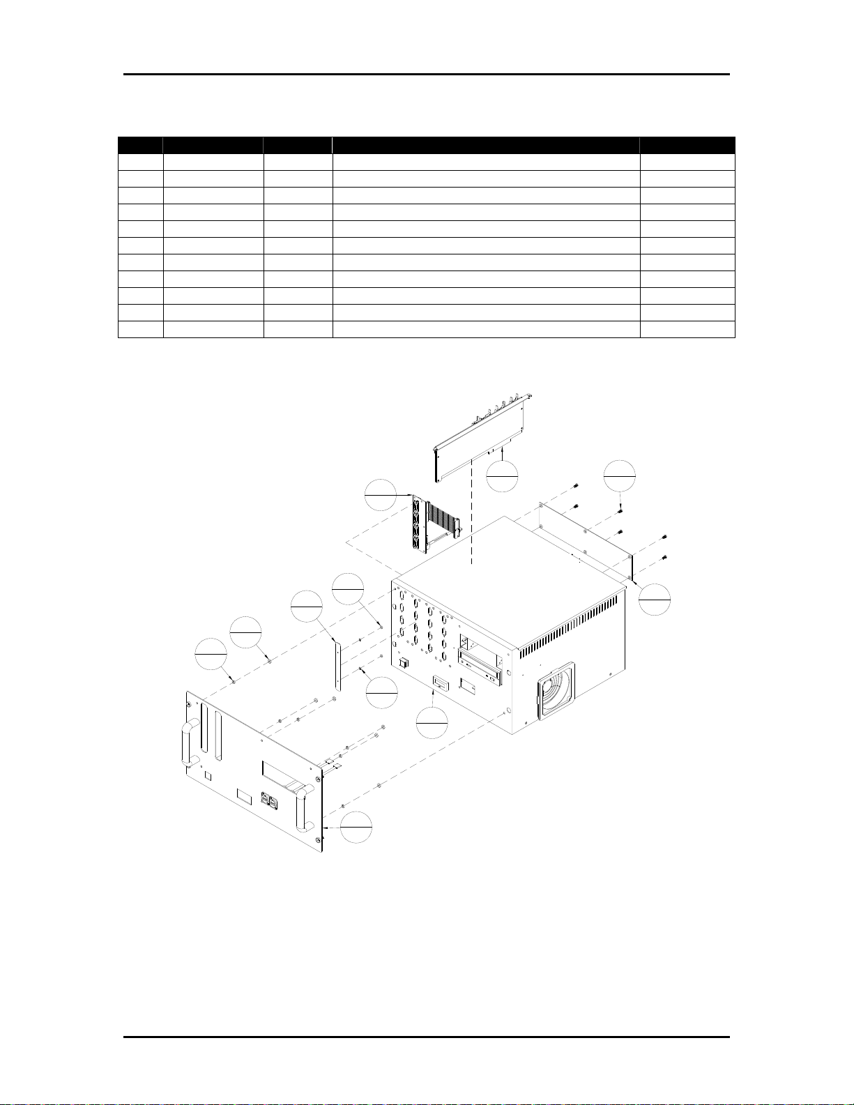
Appendix A Assembly Drawings Page A-6
Table A-5: BK-PCM-8 – Module, Computer Assembly, Universal
Item Part Number Quantity Description Reference
1 404520 6 Screw, BHCS, 10-32 UNF x 3/8”
2 420004 2 Nut, 4-40 UNC
3 420008 6 Nut, 10-32 UNF
4 439004 2 Lockwasher, No. 4
5 439009 6 Lockwasher, No. 10
6 9103177 1 Cover, Computer Cabinet
7 9104116A 1 HeadIF Assembly Page A-10
8 9104127 1 Bracket, Blocking 4-Channel
9 9104130A 1 Computer PCM Chassis Assembly Page A-12
10 9104135A 1 Image Accelerator Card Assembly Page A-14
11 9104194A 1 Faceplate Assembly, BK-PCM-8 Page A-15
Figure A-5:
BK-PCM-8 – Module, Computer Assembly, Universal
10
7
1
2
2
8
1
3
6
5
6
4
2
9
1
1
1
6
6
1
11
1
Buskro Ltd. BK705
Page 49
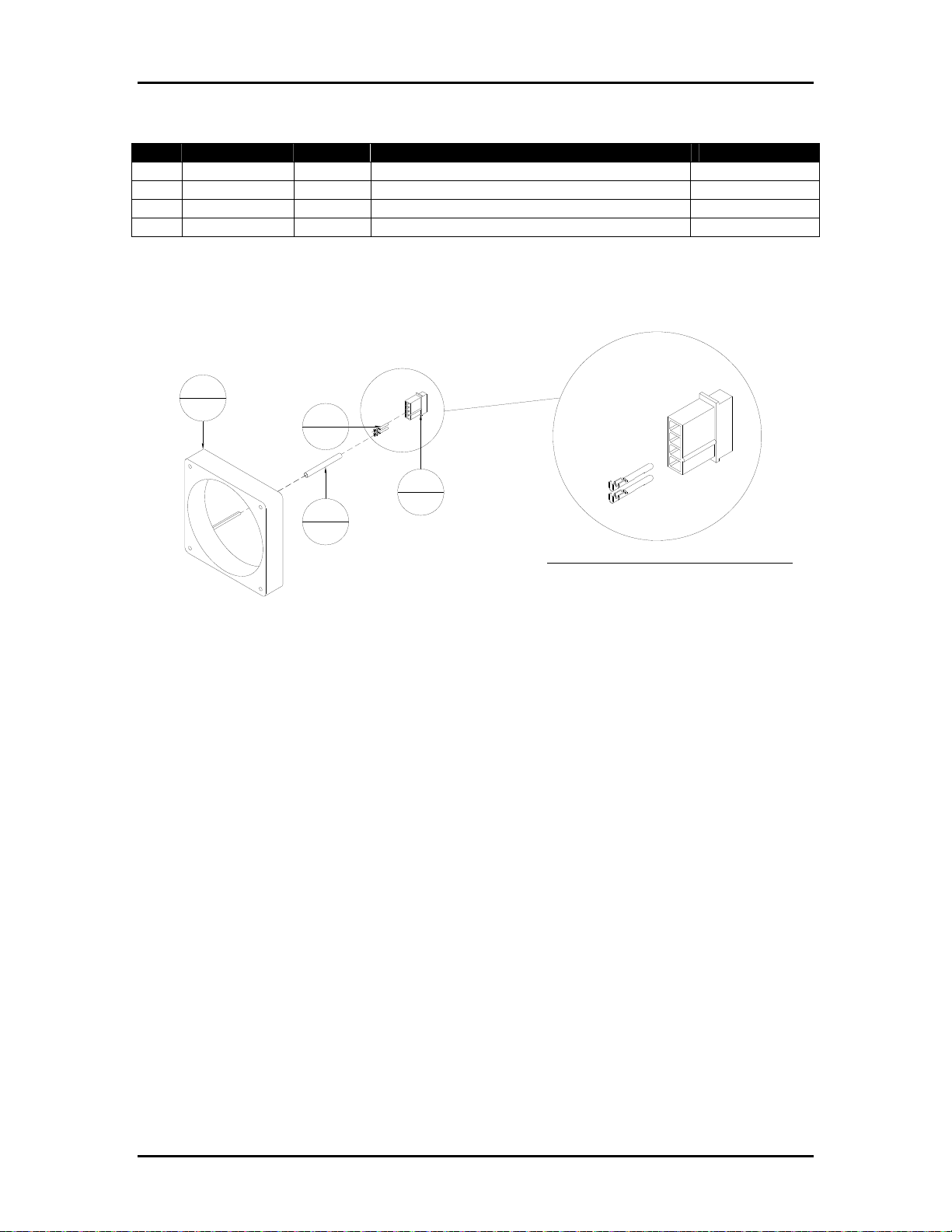
Appendix A Assembly Drawings Page A-7
Table A-6: 9102781A – Fan Assembly, 12 VDC
Item Part Number Quantity Description Reference
1 609000 1 Shrink Wrap, 3/16" I.D., 1"
2 614008 2 Contact, Male, 24-18 AWG, Mate-n-lok
3 614009 1 Connector, 4-Pin, Male, Mate-n-lok
4 9102781 1 Fan, 12VDC, Flight II 120
Figure A-6: 9102781A – Fan Assembly, 12 VDC
4
1
2
2
3
1
1
1
4
3
2
1
WIRING DETAILS FOR 614009, 4 PIN CONNECTOR:
PIN1 - RED, 12 VDC
PIN2 - BLACK, COMON
Buskro Ltd. BK705
Page 50
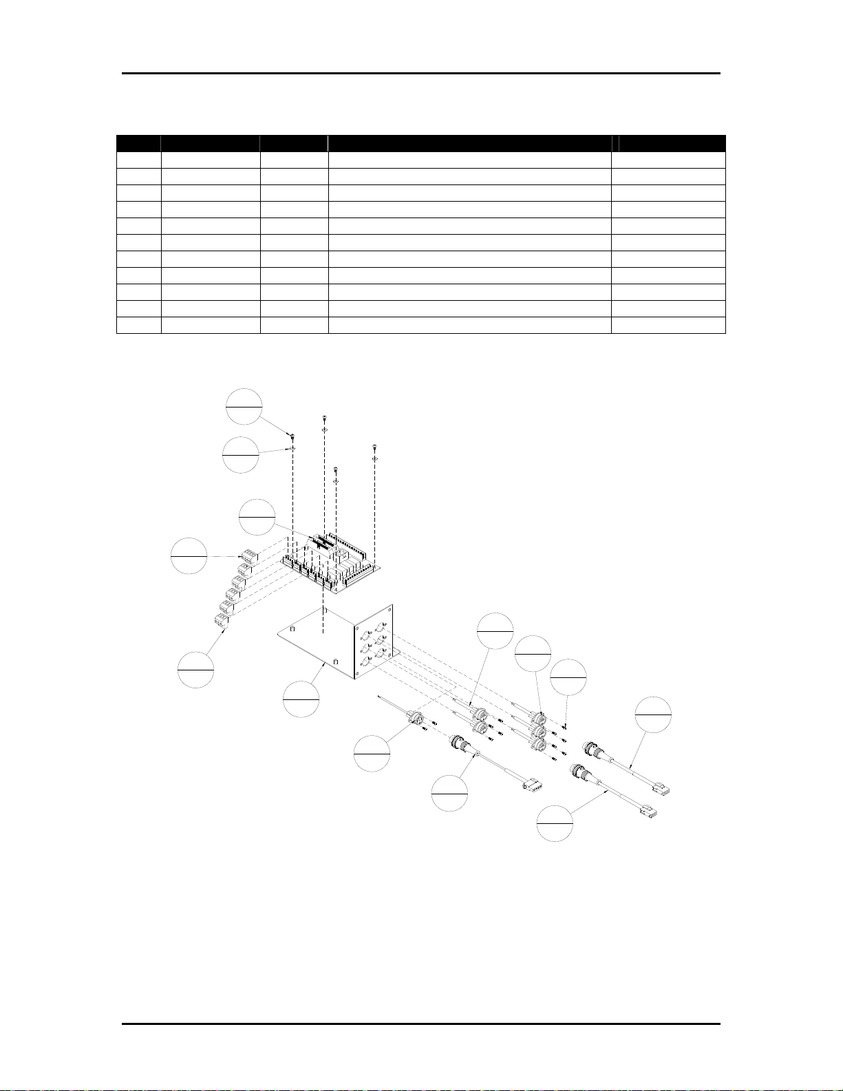
Appendix A Assembly Drawings Page A-8
Table A-7: 9103178A – Field Connection Board Assembly, BK-PCM
Item Part Number Quantity Description Reference
1 401310 12 Screw, PHMS, 4-40 UNC x 1/4"
2 402310 4 Screw, PHMS, 6-32 UNC x 1/4"
3 440530 4 Washer, #6, Nylon
4 615063 5 Connector, Female, 3-Pin, BLA3
5 615066 1 Connector, Female, 4-Pin, BLA4
6 9100711A 5 Field Sensor Cable Assembly
7 9100723A 1 Field Encoder Cable Assembly
8 9100724A 2 Jam/Proxi/Photocue Extension Cable
9 9100725A 1 Shaft Encoder Extension Cable
10 9100731 1 Board, Field Connection
11 9103178 1 Connector Plate, BK-PCM
Figure A-7:
9103178A – Field Connection Board Assembly, BK-PCM
2
4
3
4
10
1
5
1
6
5
6
4
5
11
1
7
1
5
1
12
8
2
9
1
8
2
Buskro Ltd. BK705
Page 51
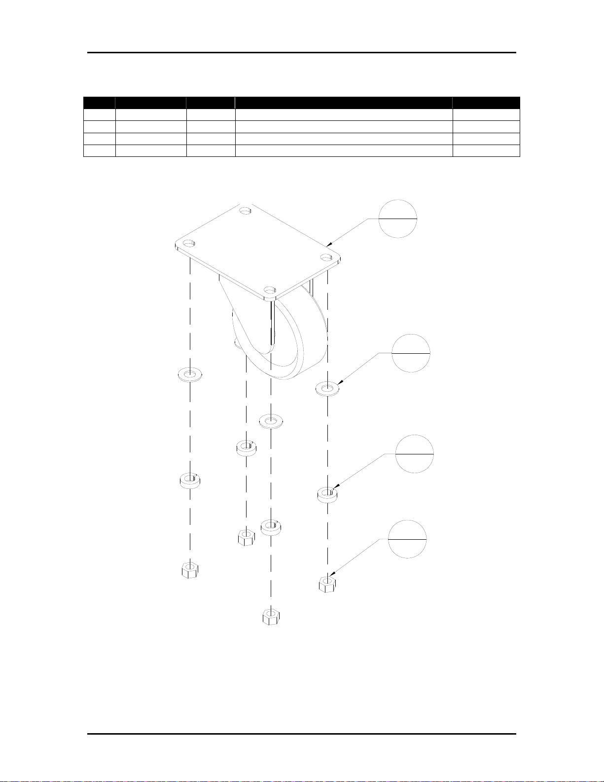
Appendix A Assembly Drawings Page A-9
Table A-8: 9103219A – Caster Wheel Assembly
Item Part Number Quantity Description Reference
1 420015 4 Nut, 5/16-18 UNC
2 439015 4 Lockwasher, 5/16 I.D.
3 440015 4 Washer, 5/16" ID
4 9103219 1 Caster Wheel, 3" dia.
Figure A-8: 9103219A – Caster Wheel Assembly
4
1
3
4
2
4
1
4
Buskro Ltd. BK705
Page 52
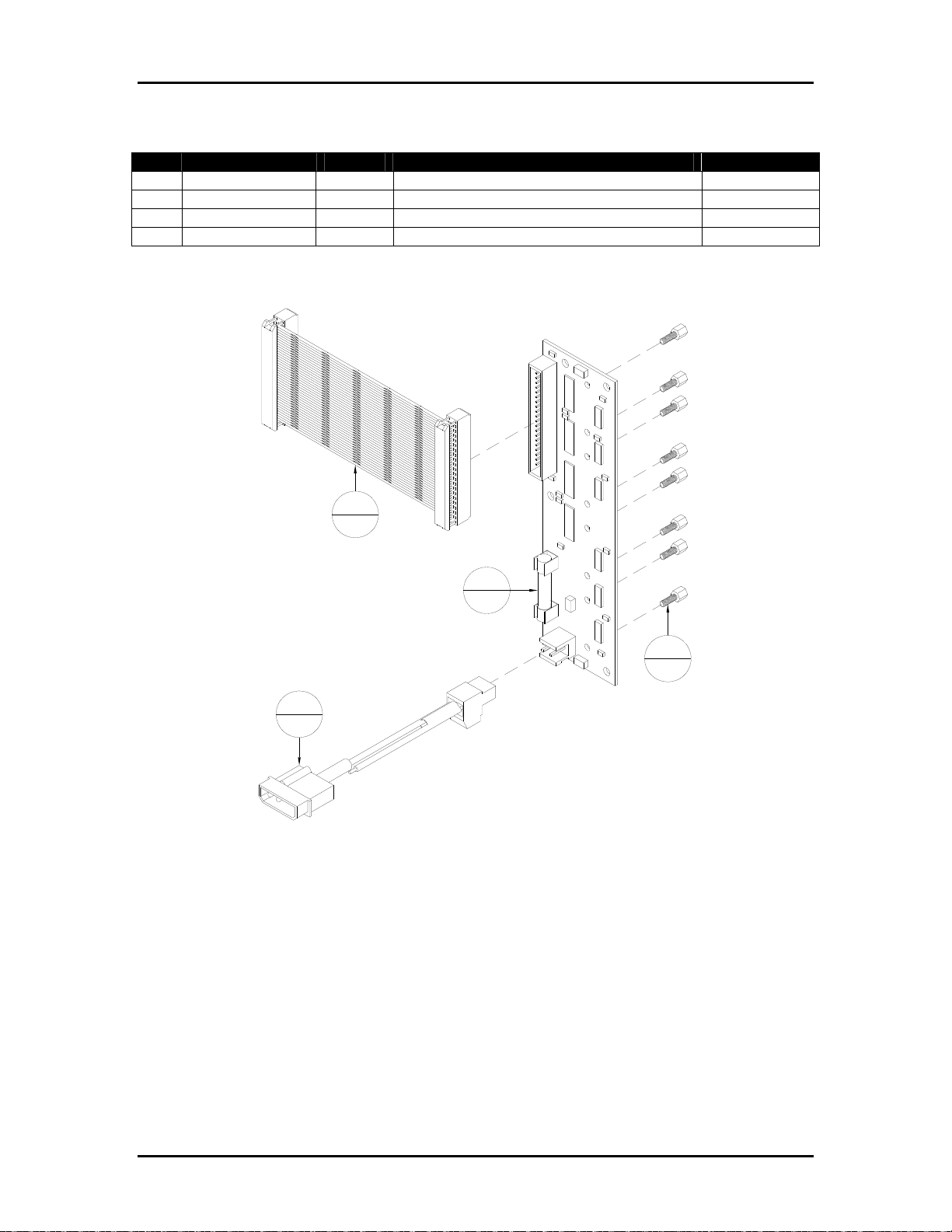
Appendix A Assembly Drawings Page A-10
Table A-9: 9104116A – HeadIF Assembly
Item Part Number Quantity Description Reference
1 615322 8 Female Screwlock, 4-40 UNC
2 9102011A 1 Cable, 12 VDC Power
3 9104116 1 Board, Head Interface (HeadIF)
4 9104334A 1 Cable, Twist Pair, HeadIF Board
Figure A-9: 9104116A – HeadIF Assembly
4
1
3
1
1
8
2
1
Buskro Ltd. BK705
Page 53
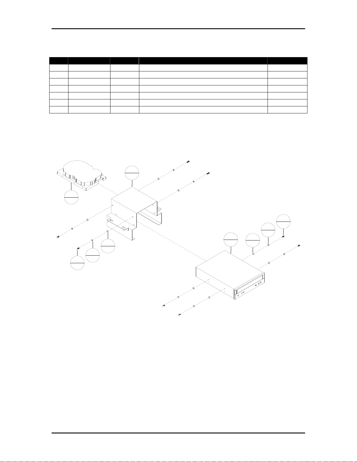
Appendix A Assembly Drawings Page A-11
Table A-10: 9104127A – Computer Drive Mount Assembly
Item Part Number Quantity Description Reference
1 402320 4 Screw, PHMS, 6-32 UNC x 3/8"
2 413506 4 Screw, BHCS, M3 x 6mm
3 439006 8 Lockwasher, No.6
4 440005 8 Washer, #6, I.D.
5 600333 1 Hard Drive, IDE
6 803601 1 CD-Rom Drive, Black
7 9102882 1 Hard Drive Mount
Figure A-10: 9104127A – Computer Drive Mount Assembly
7
1
5
1
2
4
3
8
6
4
8
3
8
1
4
1
4
8
Buskro Ltd. BK705
Page 54

Appendix A Assembly Drawings Page A-12
Table A-11: 9104130A – Computer PCM Chassis Assembly, Universal
Item Part Number Quantity Description Reference
1 401310 8 Screw, PHMS, 4-40 UNC x 1/4"
2 402310 17 Screw, PHMS, 6-32 UNC x 1/4"
3 402320 4 Screw, PHMS, 6-32 UNC x 3/8"
4 403510 4 Screw, BHCS, 8-32 UNC x 1/4"
5 404520 6 Screw, BHCS, 10-32 UNF x 3/8"
6 420007 4 Nut, 8-32 UNC
7 420008 2 Nut, 10-32 UNF
8 439009 10 Lockwasher, No. 10
9 440008 8 Washer, #10 ID
10 600101A 1 Counter Assembly, BK-PCM
11 609110 2 Connector, Push-on, Blue
12 614307A 1 Cable, I/O Assembly
13 615322 4 Female Screwlock, 4-40 UNC
14 806600 1 Software, Windows
15 9101863 1 Power Supply, 12V, ATX
16 9101971 1 Software, Compose IQ
17 9102681 1 Wire, #14, Green/Yellow Hookup, 20"
18 9102781A 1 Fan Assembly, 12 VDC Page A-7
19 9102782 1 Filter, 12VDC Fan, Flight II 120
20 9102783 1 Fan, Finger Guard Metal, Flight II 120
21 9103178A 1 Field Connection Board Assembly, BK-PCM Page A-8
22 9103185 4 Screw, FPHMS 8-32 UNC x 1 3/4"
23 9103188 6 Cover, Computer Slot
24 9103196A 1 Cable, Data Ribbon, DB9 Male
25 9103317A 1 Cable, Switch Pushbutton Assembly
26 9103471A 1 Cable, FCB Output
27 9103472A 1 Cable, FCB Input
28 9104119A 1 Cable, Controller I/O Receptacle, 18"
29 9104127A 1 Computer Drive Mount Assembly Page A-11
30 9104130 1 Enclosure, Computer DPI/DPII
31 9104133 1 Cover, Computer Module
32 9104294 1 CPU, Pentium 4, Socket 775
33 9104370 1 Card, Video, PCI Express
34 9104377 1 Cable, IDE 26" Long, Hard Drive/DVD-Rom
35 9104724 1 Motherboard, Socket 775
36 9104418 1 Bracket, DP card support
37 9104649 1 Memory, 1 GB DDR 2
Buskro Ltd. BK705
Page 55
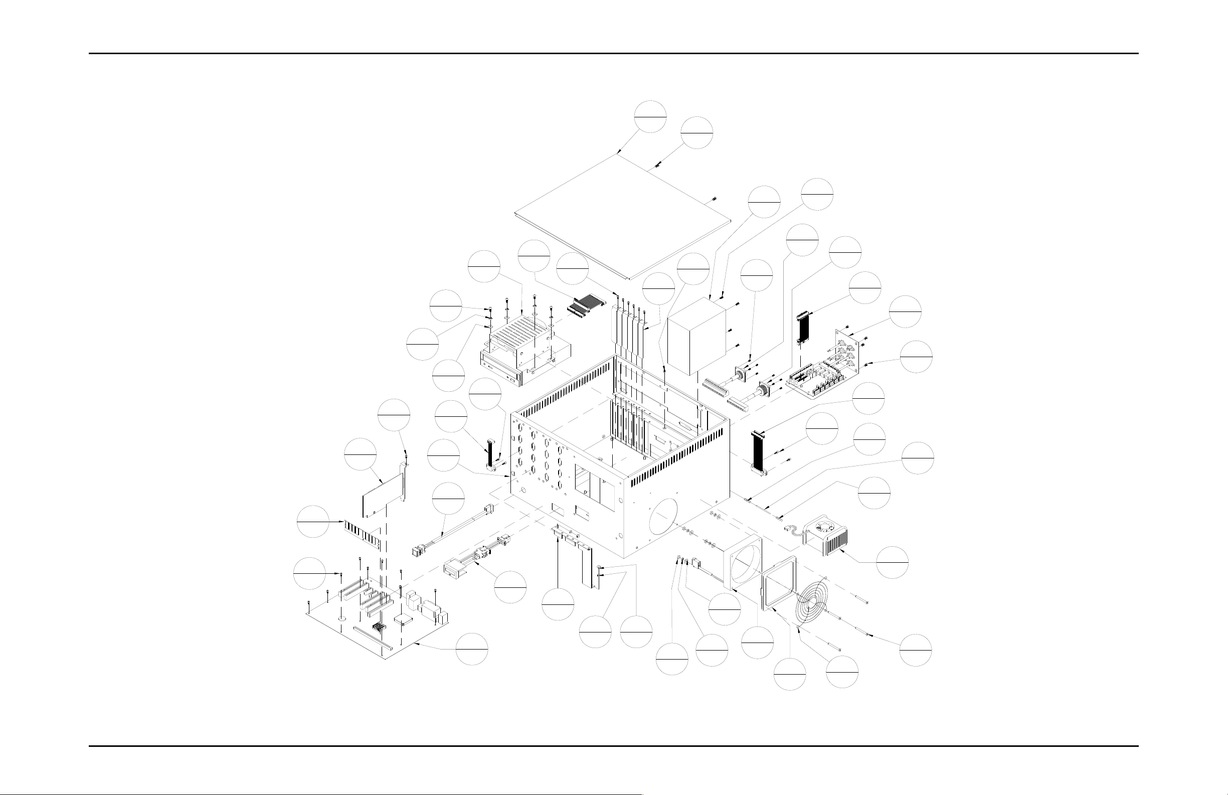
Appendix A Assembly Drawings Page A-13
Figure A-11:
9104130A – Computer PCM Chassis Assembly, Universal
8
10
2
17
33
1
31
1
34
29
1
5
6
9
8
13
4
24
1
30
1
1
2
17
23
6
5
6
15
1
2
17
1
8
3
4
27
1
26
1
12
1
21
1
4
4
28
1
13
4
11
2
17
1
25
1
37
1
2
17
35
1
10
1
Buskro Ltd. BK705
11
2
32
1
36
1
8
10
7
2
6
4
9
8
8
10
18
1
19
1
20
1
22
4
Page 56
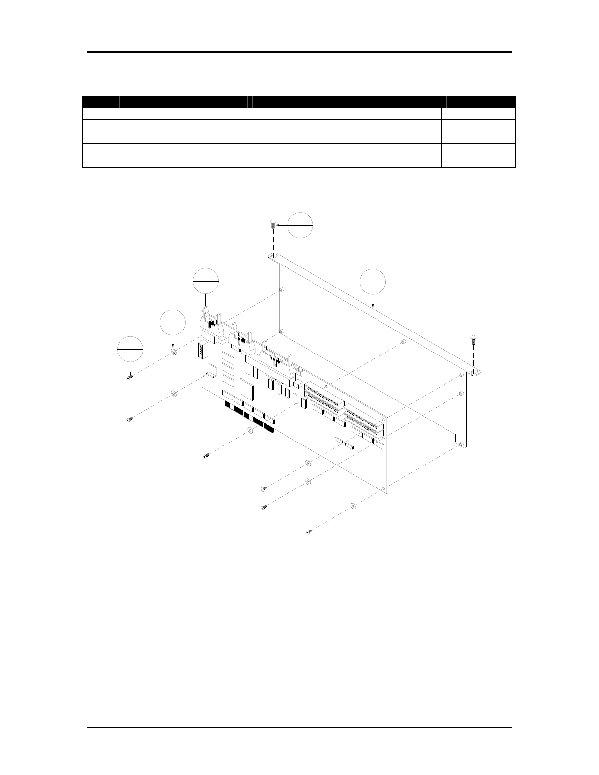
Appendix A Assembly Drawings Page A-14
Table A-12: 9104135A – Image Accelerator Card Assembly, PCM
Item Part Number Quantity Description Reference
1 401310 6 Screw, PHMS, 4-40 UNC x ¼”
2 402320 2 Screw, PHMS, 6-32 UNC x 3/8”
3 440530 6 Washer, #6, Nylon
4 9104115 1 Card, Image Accelerator
5 9104135 1 Bracket, Image Accelerator Card
Figure A-12: 9104135A – Image Accelerator Card Assembly, PCM
2
2
4
1
3
6
1
6
5
1
Buskro Ltd. BK705
Page 57
Appendix A Assembly Drawings Page A-15
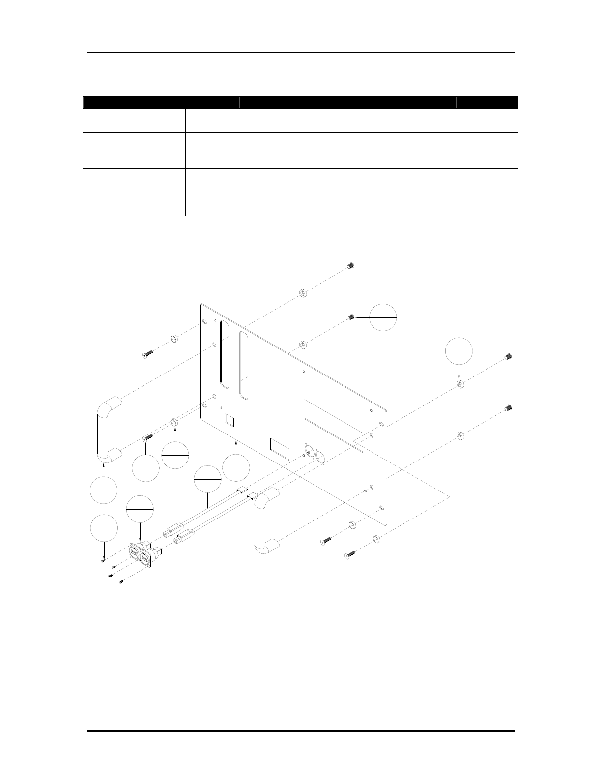
Table A-13: 9104194A – Faceplate Assembly, BK-PCM-8
Item Part Number Quantity Description Reference
1 401010 4 Screw, FHCS, 4-40 UNC x ¼”
2 404050 4 Screw, FHCS, 10-32 UNF x ¾”
3 406530 4 Screw, BHCS, 5/16-18 UNC x ½”
4 439015 4 Lockwasher, 5/16 ID
5 9102847 2 Handle, Pull, 5/16-18
6 9103315 4 Washer, Cup, 10-32 UNF Flat Head Screw
7 9104119 2 Cable, USB-B to Header
8 9104132 2 Connector, Serial Bus (USB Adapter)
9 9104194 1 Faceplate, Computer Module, 8 Channel
Figure A-13: 9104194A – Faceplate Assembly, BK-PCM-8
3
4
4
4
6
2
4
5
2
8
2
1
4
4
9
1
7
2
Buskro Ltd. BK705
Page 58
Appendix A Assembly Drawings Page A-16
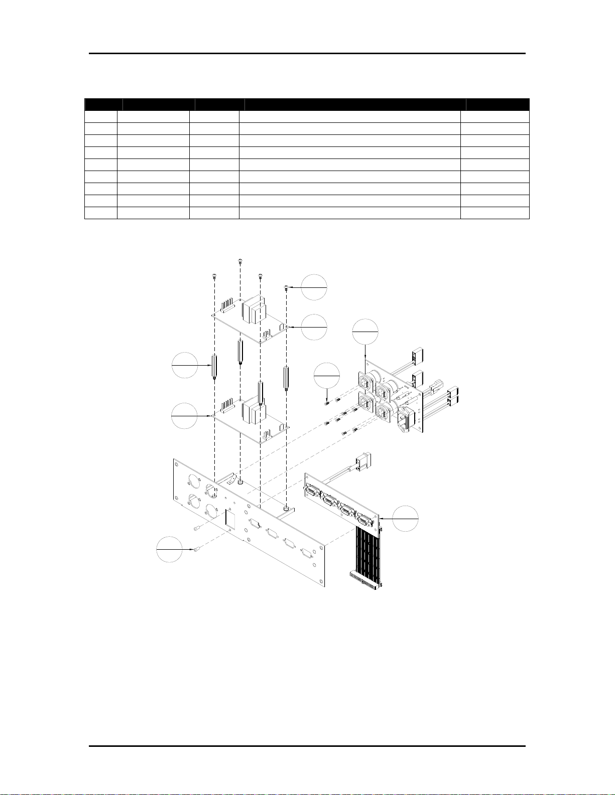
Table A-14: 9104415A – Apollo Power Supply Assembly, BK-PCM-4H
Item Part Number Quantity Description Reference
1 401010 8 Screw, FHCS, 4-40 UNC x 1/4"
2 402310 4 Screw, PHMS, 6-32 UNC x 1/4"
3 9101931 2 Rivet, Plastic
4 9102362 4 Hex Spacer, 6-32 UNC X 3/4"
5 9102418 1 Power Supply, Switching, 5.1VDC, 8A
6 9102419 1 Power Supply, Switching, 28V/1.8A
7 9102907 1 Board, HP Power Supply
8 9104116A 1 HeadIF Assembly Page A-10
9 9104416 1 Bracket, HP-PS-PCM integrated
Figure A-14: 9104415A – Apollo Power Supply Assembly, BK-PCM-4H
2
4
6
1
4
4
5
1
3
2
1
8
7
1
8
1
Buskro Ltd. BK705
Page 59
Appendix A Assembly Drawings Page A-17
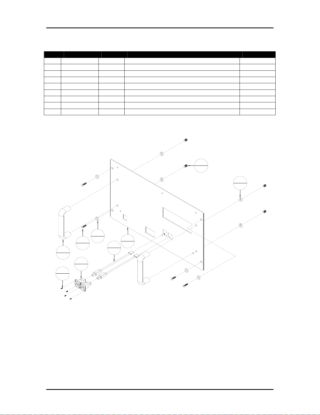
Table A-15: 9104423A – Faceplate assembly, BK-PCM-4H
Item Part Number Quantity Description Reference
1 401010 4 Screw, FHCS, 4-40 UNC x 1/4"
2 404050 4 Screw, FHCS, 10-32 UNF x 3/4"
3 406530 4 Screw, BHCS, 5/16-18 UNC X 1/2"
4 439015 4 Lockwasher, 5/16 I.D.
5 9102847 2 Handle, Pull, 5/16-18
6 9103315 4 Washer, Cup, 10-32 UNF flat head screw
7 9104119 2 Cable, USB-B to header
8 9104132 2 Connector, Serial Bus (USB adapter)
9 9104423 1 Faceplate, PCM-4H
Figure A-15: 9104423A – Faceplate assembly, BK-PCM-4H
3
4
4
4
6
4
2
4
5
2
8
2
1
4
9
1
7
2
Buskro Ltd. BK705
Page 60
Appendix A Assembly Drawings Page A-18
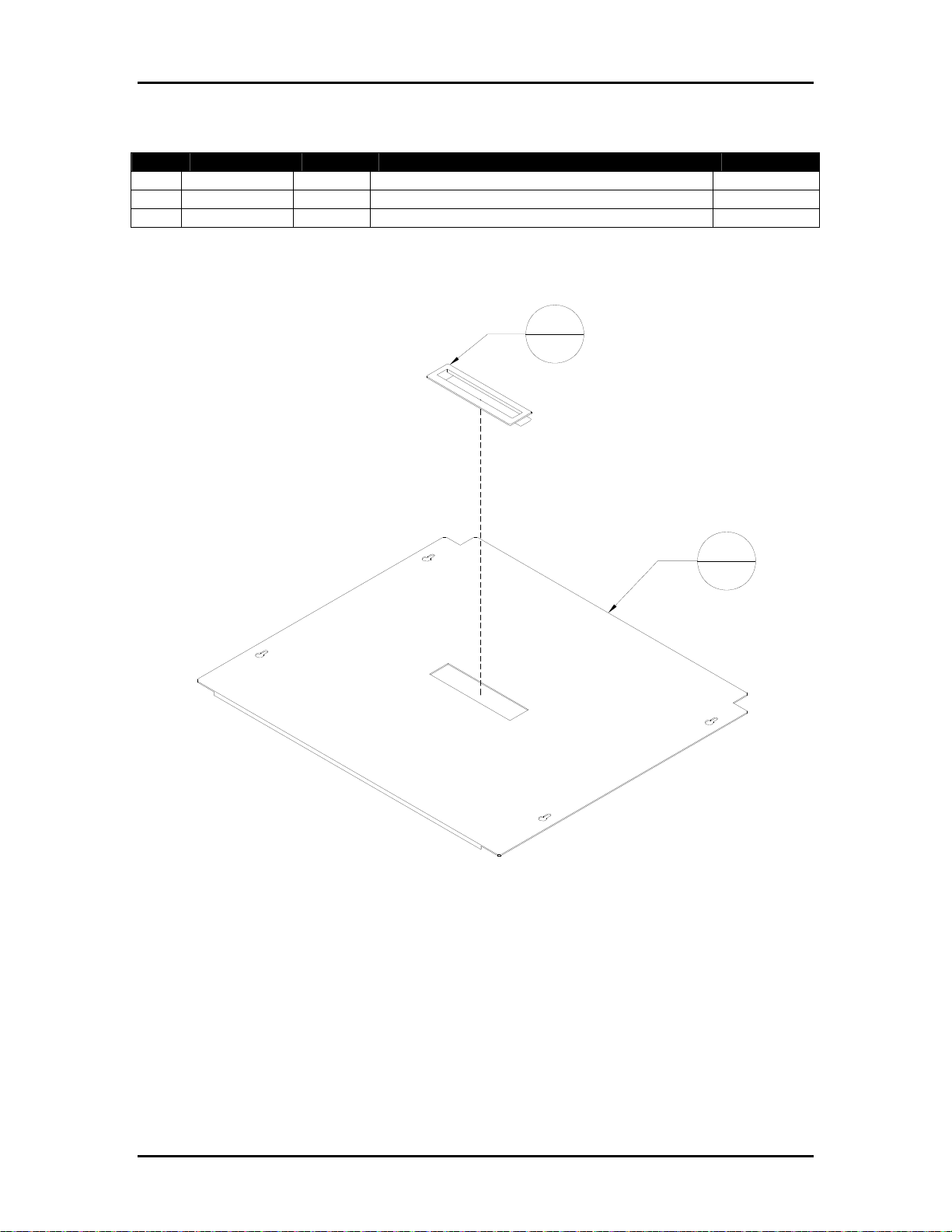
Table A-16: 9104466A – Back Cover Assembly
Item Part Number Quantity Description Reference
1 609110 2 Connector, Push-On, 16-14 AWG, Blue
2 9104466 1 Cover, Back
3 9101640 1 Handle, Panel Snap Style
Figure A-16: 9104466A – Back Cover Assembly
3
1
2
1
Buskro Ltd. BK705
Page 61
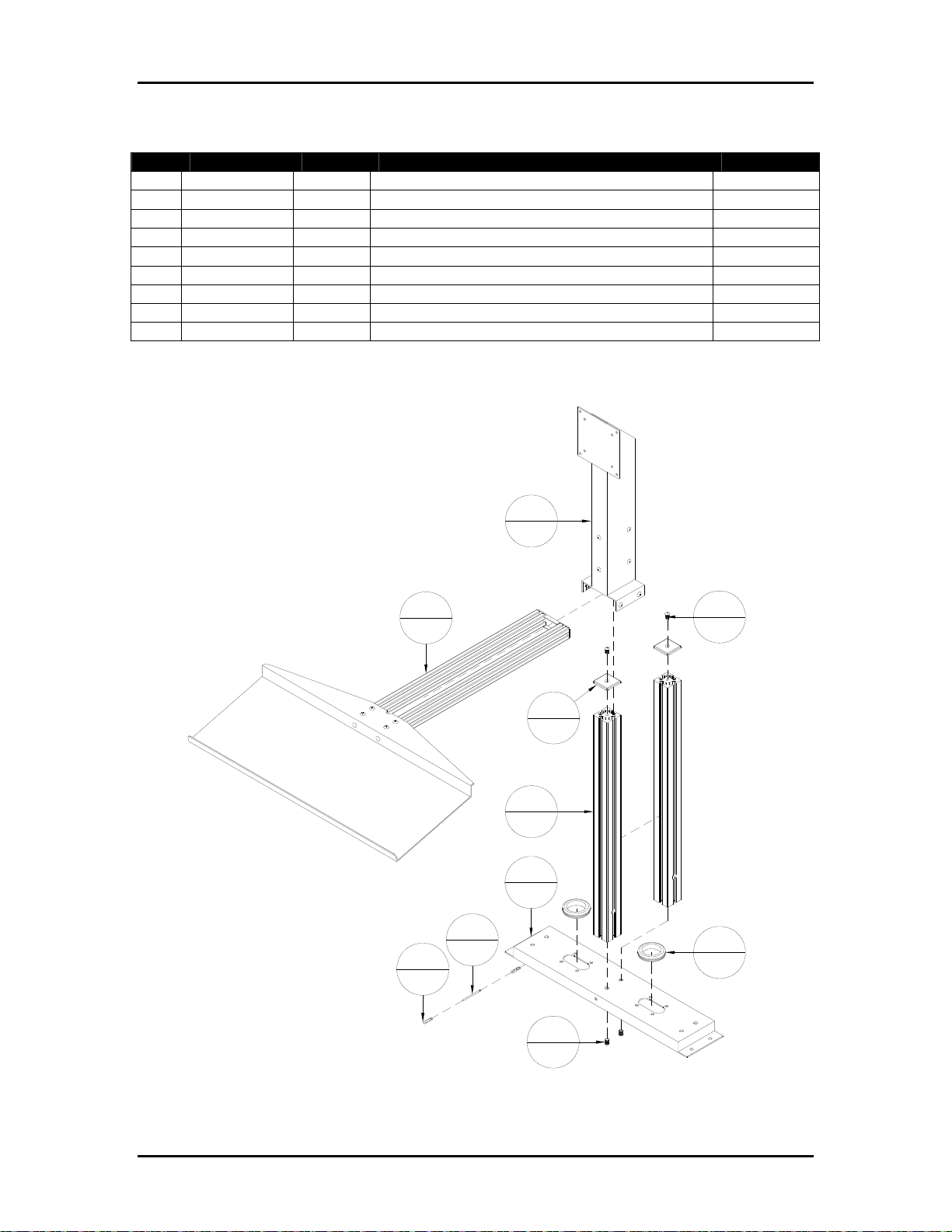
Appendix A Assembly Drawings Page A-19
Table A-17: 9104486A – Monitor/Keyboard Stand, BK705
Item Part Number Quantity Description Reference
1 406530 4 Screw, BHCS, 5/16-18 UNC X 1/2"
2 609110 2 Connector, Push-on, 16-14 AWG, Blue
3 9101624 2 End Caps (15 Series)
4 9102232 2 Frame, Monitor Mount Leg
5 9102681 1 Wire, #14, Green/Yellow Hookup, 3" Lg.
6 9103859 2 Rubber Grommet, 1.5" I.D.
7 9104486 1 Bracket, Monitor Stand Cross Member
8 9104487A 1 Keyboard Tray Assembly, BK705 Page A-20
9 9104488A 1 Monitor Stand Assembly, BK705 Page A-21
Figure A-17:
9104486A – Monitor/Keyboard Stand, BK705
9
1
8
1
3
2
4
2
1
4
7
1
5
1
2
2
1
4
6
2
Buskro Ltd. BK705
Page 62
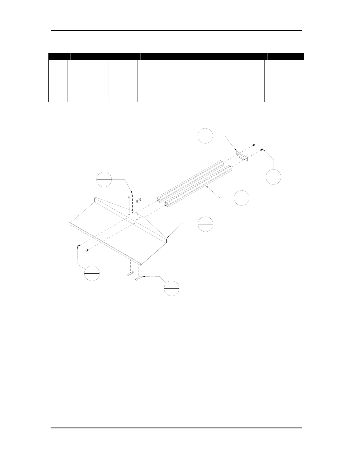
Appendix A Assembly Drawings Page A-20
Table A-18: 9104487A – Telescopic Arm/tray Assembly
Item Part Number Quantity Description Reference
1 405520 4 Screw, BHCS, 1/4-20 UNC, 3/8"
2 405530 4 Screw, BHCS, 1/4-20 UNC x 1/2"
3 9101126 2 T-Nut, 1/4-20 UNC, Double
4 9104431 2 Extrusion Rail, 1 x 1 x 20"
5 9104487 1 Tray, Keyboard/Mouse
6 9104489 1 Endcap, Square rail
Figure A-18: 9104487A – Telescopic Arm/tray Assembly
6
1
1
4
4
2
5
1
2
4
3
2
2
4
Buskro Ltd. BK705
Page 63
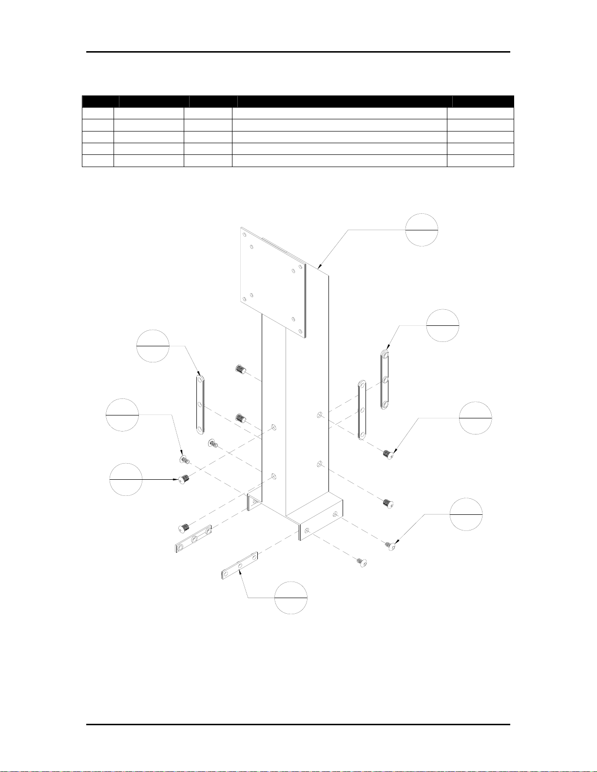
Appendix A Assembly Drawings Page A-21
Table A-19: 9104488A – Stand Assembly
Item Part Number Quantity Description Reference
1 405520 4 Screw, BHCS, 1/4-20 UNC, 3/8"
2 406530 6 Screw, BHCS, 5/16-18 UNC x 1/2 in
3 9100361 2 T-Nut, 1/4-20 Triple
4 9102074 3 T-Nut, Triple, 5/16-18 UNC
5 9104488 1 Stand, Support
Figure A-19: 9104488A – Stand Assembly
5
1
4
3
4
3
1
4
2
6
3
2
2
6
1
4
Buskro Ltd. BK705
Page 64

Appendix A Assembly Drawings Page A-22
Table A-20: 9104912A – Power Distribution Box Assembly, BK705
Item Part Number Quantity Description Reference
1 401010 12 Screw, FHCS, 4-40 UNC x ¼”
2 420008 2 Nut, 10-32 UNF
3 420010 1 Nut, ¼-20 UNC
4 439007 1 Lockwasher, ¼”, External Tooth
5 439008 2 Lockwasher, #10, External Tooth
6 439009 2 Lockwasher, #10
7 439010 1 Lockwasher, ¼” ID
8 606000 1 Wire, #16, Black, 6” Lg.
9 606000 1 Wire, #16, Black, 4” Lg.
10 606000 4 Wire, #16, Black, 4” Lg.
11 606000 1 Wire, #16, Black, 4” Lg.
12 606008 1 Wire, #14, White, 6” Lg.
13 606009 1 Wire, #16, White, 6” Lg.
14 606009 1 Wire, #16, White, 4” Lg.
15 606009 4 Wire, #16, White, 4” Lg.
16 606009 1 Wire, #16, White, 4” Lg.
17 609010 1 Wire, #14, Black, 6” Lg.
18 606037 1 Wire, #22, Black, 4” Lg.
19 606038 1 Wire, #22, White, 4” Lg.
20 606359 5 Wire, #16, Green/Yellow, 4” Lg.
21 609001 1 Shrink Wrap, ¼” ID, 1” Lg.
22 609110 6 Connector, Push-on, 16-14 AWG, Blue
23 609111 3 Terminal, Ring, #10, 16-14 AWG, Blue
24 609113 15 Connector, Push-On, Yellow
25 609120 1 Terminal, Ring, ¼”, 16-14 AWG, Non-Insulated
26 609530 2 Connector, Push-On, 22-18 AWG, Red
27 9102247 2 Shrink Wrap, ½” ID
28 9102601 1 Switch, Rocker, 250VAC/10A, DPST
29 9102681 2 Wire, #14, Green/Yellow, 6” Lg.
30 9103167 5 Receptacle, Female, 120 VAC, 15A, IEC
31 9103308 2 Contact, Female, 20-14 AWG, Mate-n-lok
32 9103827 2 Fuse Holder, Panel Mount, Shock Proof
33 9103894 1 Plug, 2-Circuit, Universal Mate-n-lok
34 9104632 1 Filter, RFI, EEJ Series
35 9104912 1 Bracket, Power Distribution
36 9104926 1 Light, Pilot, Green
Buskro Ltd. BK705
Page 65
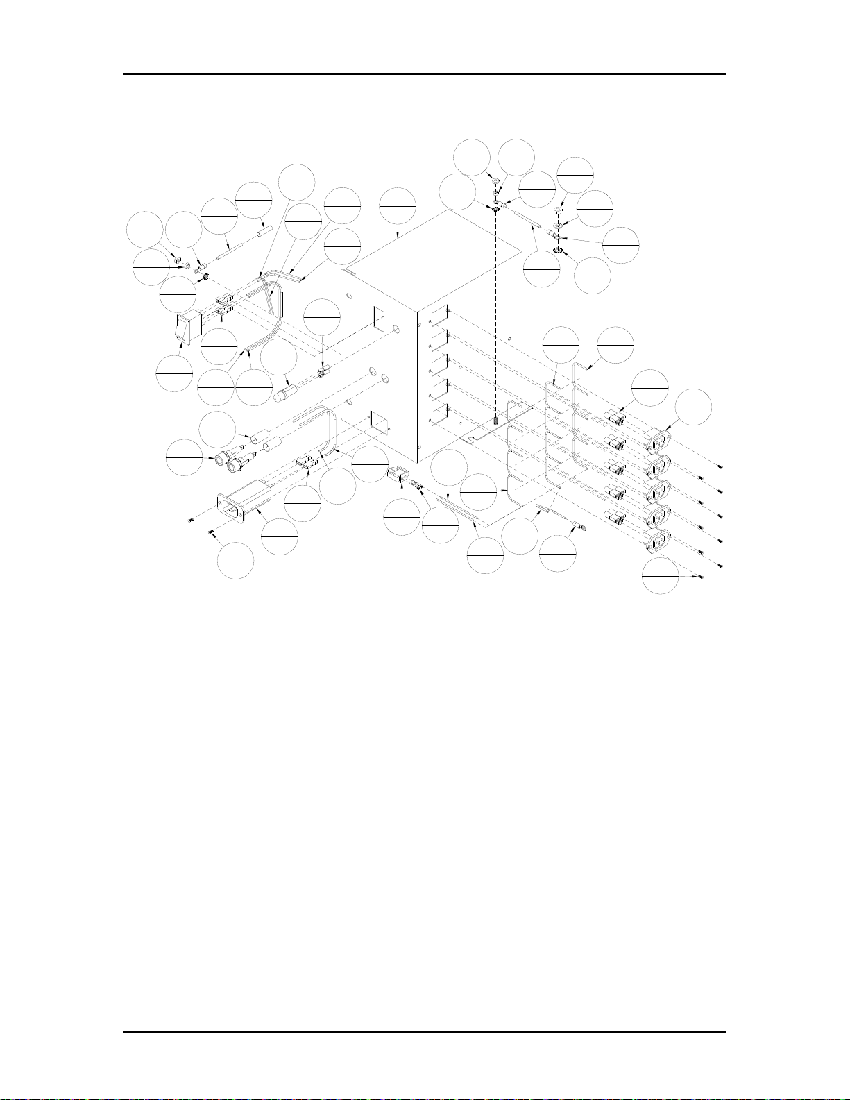
Appendix A Assembly Drawings Page A-23
Figure A-20: 9104912A - Power Distribution Box Assembly, BK705
2
2
19
21
29
2
2
6
2
28
1
2
23
3
5
2
22
6
13
1
27
2
32
2
1
12
1
1
36
1
8
1
34
1
14
18
22
1
1
9
1
26
2
12
1
6
35
1
17
1
33
1
5
2
11
1
15
31
2
6
2
4
20
5
16
1
3
1
23
3
29
2
7
1
25
1
4
1
20
5
23
3
10
4
24
15
30
5
1
12
Buskro Ltd. BK705
Page 66
Appendix A Assembly Drawings Page A-24
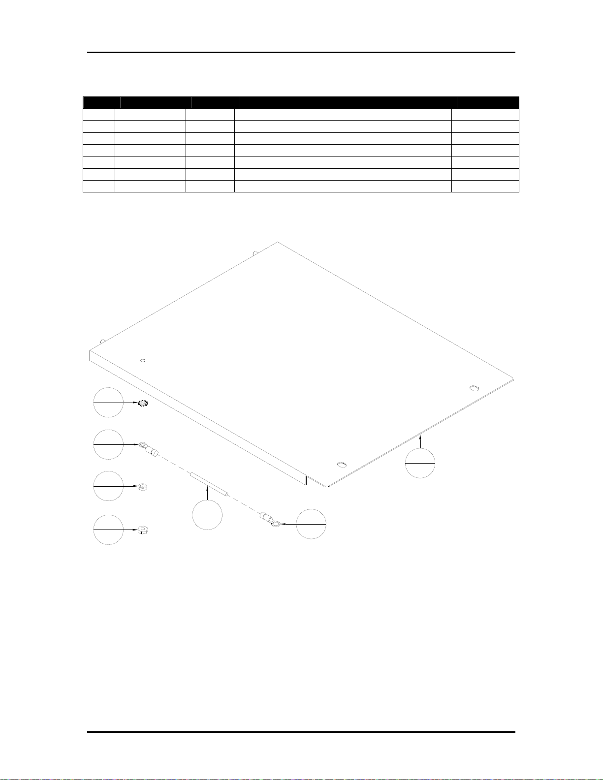
Table A-21: 9104913A – Cover Assembly, BK705
Item Part Number Quantity Description Reference
1 420008 1 Nut, 10-32 UNF
2 439008 1 Lockwasher, #10, External Tooth
3 439009 1 Lockwasher, #10
4 609111 1 Terminal, Ring, #10, 16-14 AWG, Blue
5 609120 1 Terminal, Ring, ¼”, 16-14 AWG, Non-Insulated
6 9102681 1 Wire, #14, Green/Yellow, 20” Lg.
7 9104913 1 Cover, Ezejet Rear
Figure A-21: 9104913A – Cover Assembly, BK705
2
1
4
1
7
1
3
1
6
1
1
1
5
1
Buskro Ltd. BK705
Page 67

Ink Specific Drawings
B.0 Ink Specific Drawings
List of Tables
Table B-1: BK705AU – Controller, BK705 Atlas Monet..............................................B-1
Table B-2: BK705CU – Controller, BK705 Atlas Cezanne...........................................B-2
Table B-3: BK705UU – Controller, BK705 Aurora ......................................................B-3
Table B-4: BK-IWM-2A – Inkwell Module, 2-Channel Monet ....................................B-4
Table B-5: BK-IWM-2C – Inkwell Module, 2-Channel Cezanne .................................B-5
Table B-6: BK-IWM-2U – Inkwell Module, 2-Channel Aurora....................................B-6
Table B-7: BK-PVM-700 – Pressure Regulator, 2-Channel..........................................B-7
Table B-8: 705-IDM4H-15NA - Apollo IDM, 4" BK705, 15', N. America.................B-8
Table B-9: 705-IDM4H-15WD – Apollo IDM, 4" BK705, 15', World.........................B-9
Table B-10: 9101767A – Pumping Station Assembly, Atlas (Monet & Cezanne)......B-10
Table B-11: 9101780A – Pumping Station Assembly, Aurora....................................B-11
Table B-12: 9102132A – Bottle Coupling Assembly, Monet......................................B-12
Table B-13: 9102147A – Ink Line Assembly ..............................................................B-13
Table B-14: 9102960A – Flow Control, Meniscus Vacuum........................................B-14
Table B-15: 9103020A – Flow Control, Purge Pressure..............................................B-15
Table B-16: 9103390A – Filter, Assembly, 10 μm......................................................B-16
Table B-17: 9103677A – Cover, Blank 6U..................................................................B-17
Table B-18: 9103680A – Universal Enclosure Assembly............................................B-18
Table B-19: 9103683A – Solenoid Valve Assembly ...................................................B-19
Table B-20: 9103764A – Power Distribution Box Assembly......................................B-20
Table B-21: 9103766A – Ink Delivery Module, BK705 Atlas (Monet & Cezanne) ...B-21
Table B-22: 9103767A – Inkwell Module, 2-Channel Atlas (Monet & Cezanne) ......B-23
Table B-23: 9103776A – Ink Delivery Module, BK705 Aurora .................................B-24
Table B-24: 9103784A – Ink Reservoir Assembly, BK705.........................................B-26
Table B-25: 9103910A – Bottle Coupling Assembly, Cezanne...................................B-28
Table B-26: 9104497A – Bottle Coupling Assembly, Aurora.....................................B-29
Table B-27: 9104661A – Reservoir Cover Assembly..................................................B-30
Table B-28: Ezejet with optional Apollo Ink Delivery Module (For Reference) ........B-31
Appendix B
Buskro Ltd. BK705
Page 68

Appendix B Ink Specific Drawings
List of Figures
Figure B-1: BK705AU – Controller, BK705 Atlas Monet.............................................B-1
Figure B-2: BK705CU – Controller, BK705 Atlas Cezanne .........................................B-2
Figure B-3: BK705UU – Controller, BK705 Atlas Aurora............................................B-3
Figure B-4: BK-IWM-2A – Inkwell Module, 2-Channel Monet...................................B-4
Figure B-5: BK-IWM-2C – Inkwell Module, 2-Channel Cezanne................................B-5
Figure B-6: BK-IWM-2U – Inkwell Module, 2-Channel Aurora ..................................B-6
Figure B-7: BK-PVM-700 – Pressure Regulator, 2-Channel.........................................B-7
Figure B-8: 705-IDM4H-15NA – Apollo IDM, 4" BK705, 15', N. America ................B-8
Figure B-9: 705-IDM4H-15WD – Apollo IDM, 4" BK705, 15', World........................B-9
Figure B-10: 9101767A – Pumping Station Assembly, Atlas (Monet & Cezanne).....B-10
Figure B-11: 9101780A – Pumping Station Assembly, Aurora...................................B-11
Figure B-12: 9102132A – Bottle Coupling Assembly, Monet.....................................B-12
Figure B-13: 9102147A – Ink Line Assembly .............................................................B-13
Figure B-14: 9102960A – Flow Control, Meniscus Vacuum.......................................B-14
Figure B-15: 9103020A – Flow Control, Purge Pressure.............................................B-15
Figure B-16: 9103390A – Filter, Assembly, 10 μm.....................................................B-16
Figure B-17: 9103677A – Cover, Blank 6U.................................................................B-17
Figure B-18: 9103680A – Universal Enclosure Assembly ..........................................B-18
Figure B-19: 9103683A – Solenoid Valve Assembly..................................................B-19
Figure B-20: 9103764A – Power Distribution Box Assembly.....................................B-20
Figure B-21: 9103766A – Ink Delivery Module, BK705 Atlas (Monet & Cezanne)..B-22
Figure B-22: 9103767A – Inkwell Module, 2-Channel Atlas (Monet & Cezanne).....B-23
Figure B-23: 9103776A – Ink Delivery Module, BK705 Aurora ................................B-25
Figure B-24: 9103784A – Ink Reservoir Assembly, BK705........................................B-27
Figure B-25: 9103910A – Bottle Coupling Assembly, Cezanne .................................B-28
Figure B-26: 9104497A – Bottle Coupling Assembly, Aurora....................................B-29
Figure B-27: 9104661A – Reservoir Cover Assembly.................................................B-30
Figure B-28: Ezejet with optional Apollo Ink Delivery Module (For Reference).......B-31
Buskro Ltd. BK705
Page 69
Appendix B Ink Specific Drawings
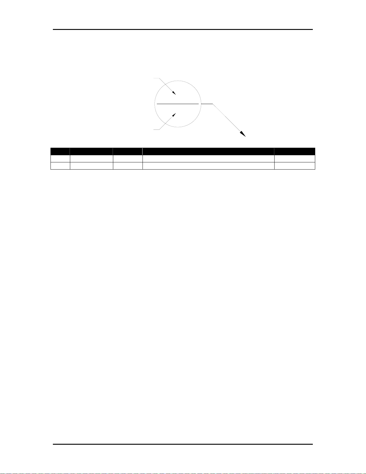
Balloon Annotation and Parts Listing
Item Number
5
8
Quantity
Item Part Number Quantity Description Reference
1
2
The following is a description of how to interpret the information in this section:
Item:
This column indicates the item number used for each unique part in an assembly drawing.
It is matched with the top number in the balloon pointing at the associated part.
Part Number:
This column represents the Buskro part number.
Quantity:
This represents the total number of a given part in an assembly. It is matched with the
bottom number in the balloon pointing at the associated part.
Description:
This column contains a brief description of the part.
Reference:
This column indicates the page location for sub-assemblies.
Buskro Ltd. BK705
Page 70
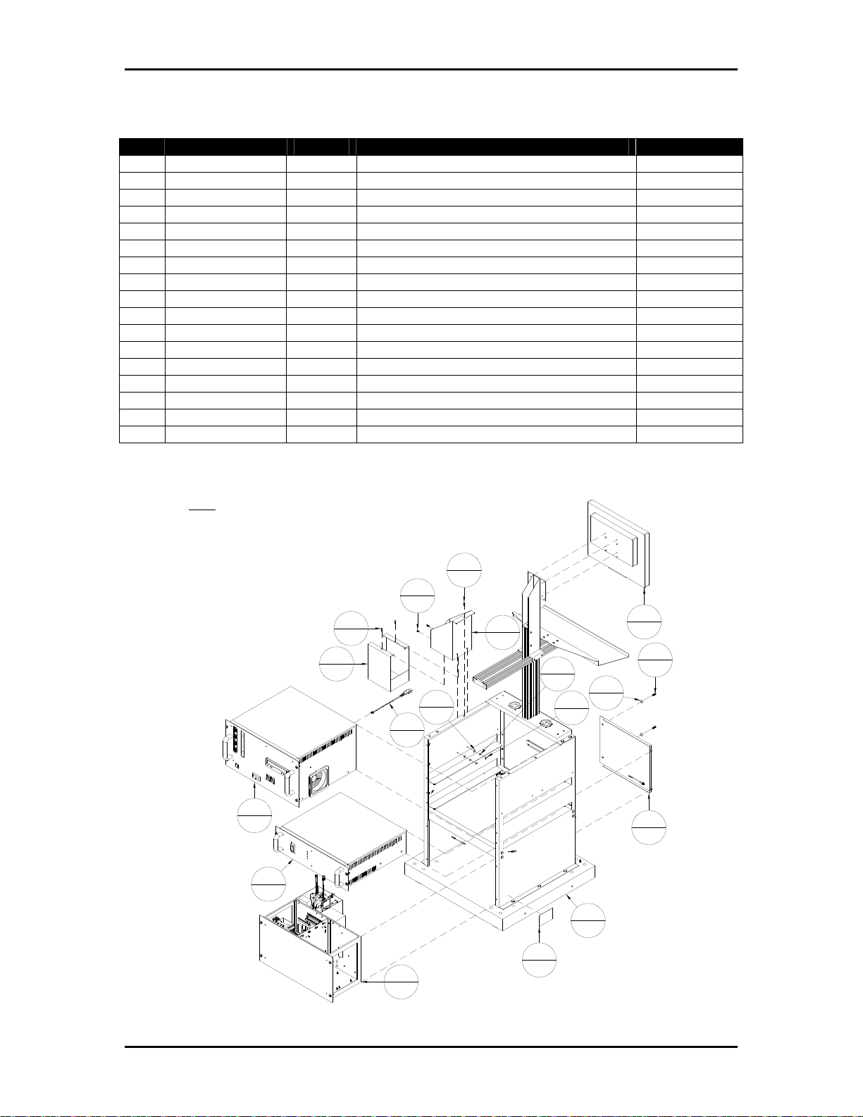
Appendix B Ink Specific Drawings Page B-1
Table B-1: BK705AU – Controller, BK705 Atlas Monet
Item Part Number Quantity Description Reference
1 404050 2 Screw, FHCS, 10-32 UNF x ¾”
2 404520 4 Screw, BHCS, 10-32 UNF x 3/8”
3 405520 1 Screw, BHCS, ¼-20 UNC x 3/8”
4 420008 8 Nut, 10-32 UNF
5 439009 8 Lockwasher, No. 10
6 440008 2 Washer, #10
7 9101627 1 Buskro Serial Number Label
8 9103285A 1 Dongle Assembly
9 9103315 2 Washer, Cup, 10-32 UNF Flat Head
10 9104907 1 Bracket, Ink Bottle, BK705
11 9104909 1 Spill Tray
12 9104913A 1 Cover Assembly, BK705
13 BK705-ST 1 Controller Stand, BK705 Appendix A
14 BK-IWM-2A 1 Inkwell Module, 2-Channel Monet Page B-4
15 BK-MON-LCD17 1 Monitor, 17” LCD
16 BK-PCM-8 1 Module, Computer Assembly Appendix A
17 BK-PSM-4A 1 Module, Power Supply, Atlas/Aurora Appendix C
Figure B-1: BK705AU – Controller, BK705 Atlas Monet
NOTE:
BK-PSM-4A IS SHOWN FOR REFERENCE. IT IS
INCLUDED FOR THE NORTH AMERICAN CASE
(115VAC). FOR THE REST OF THE WORLD
(200/230VAC), BK-PSM-4A-WD IS USED.
11
1
16
1
17
1
2
4
2
4
8
1
3
1
6
2
15
10
1
5
2
4
2
1
1
2
9
2
12
1
13
1
7
14
1
1
Buskro Ltd. BK705
Page 71
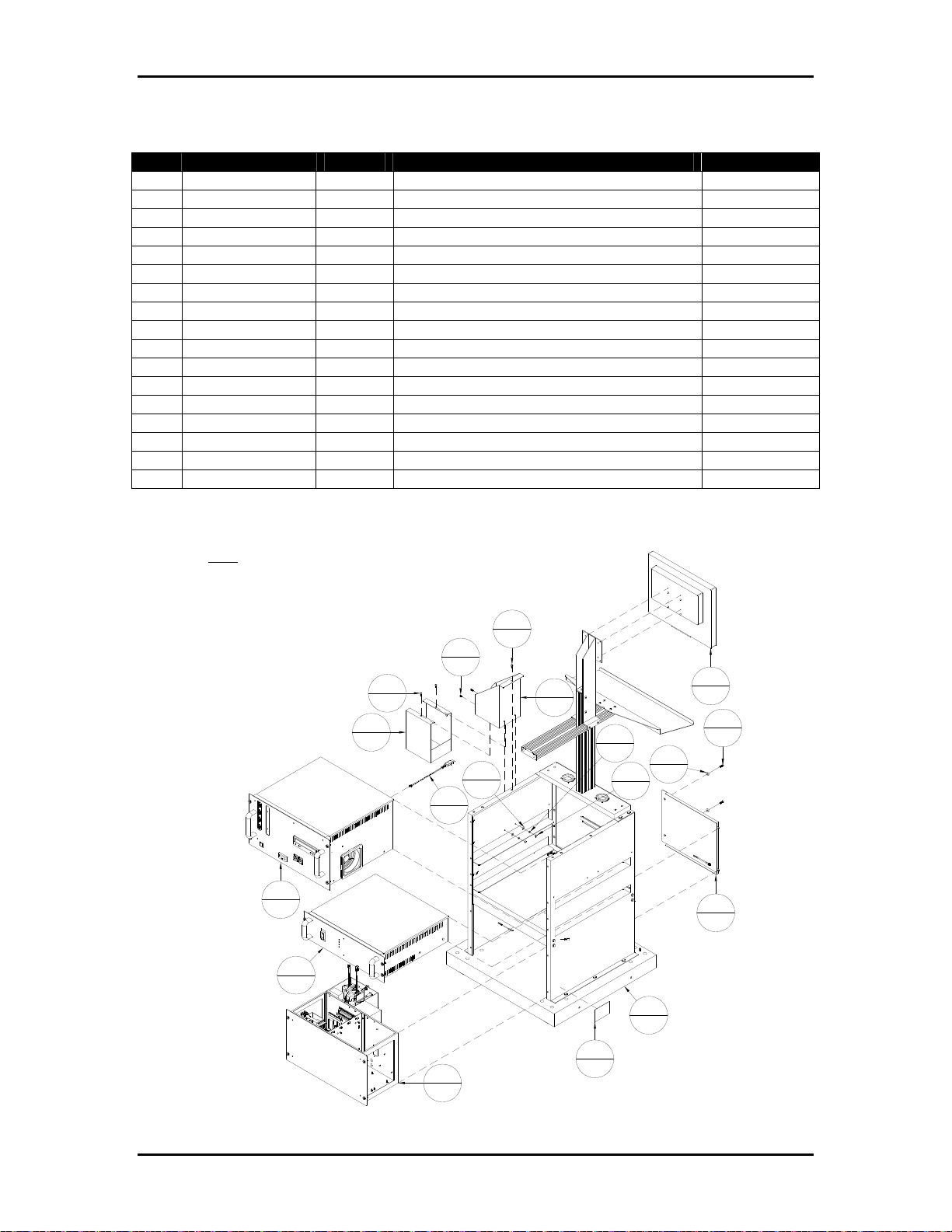
Appendix B Ink Specific Drawings Page B-2
Table B-2: BK705CU – Controller, BK705 Atlas Cezanne
Item Part Number Quantity Description Reference
1 404050 2 Screw, FHCS, 10-32 UNF x ¾”
2 404520 4 Screw, BHCS, 10-32 UNF x 3/8”
3 405520 1 Screw, BHCS, ¼-20 UNC x 3/8”
4 420008 8 Nut, 10-32 UNF
5 439009 8 Lockwasher, No. 10
6 440008 2 Washer, #10
7 9101627 1 Buskro Serial Number Label
8 9103285A 1 Dongle Assembly
9 9103315 2 Washer, Cup, 10-32 UNF Flat Head
10 9104907 1 Bracket, Ink Bottle, BK705
11 9104909 1 Spill Tray
12 9104913A 1 Cover Assembly, BK705
13 BK705-ST 1 Controller Stand, BK705 Appendix A
14 BK-IWM-2C 1 Inkwell Module, 2-Channel Cezanne Page B-5
15 BK-MON-LCD17 1 Monitor, 17” LCD
16 BK-PCM-8 1 Module, Computer Assembly Appendix A
17 BK-PSM-4A 1 Module, Power Supply, Atlas/Aurora Appendix C
Figure B-2: BK705CU – Controller, BK705 Atlas Cezanne
NOTE:
BK-PSM-4A IS SHOWN FOR REFERENCE. IT IS
INCLUDED FOR THE NORTH AMERICAN CASE
(115VAC). FOR THE REST OF THE WORLD
(200/230VAC), BK-PSM-4A-WD IS USED.
11
1
16
1
17
1
2
4
2
4
8
1
3
1
10
1
6
2
15
1
1
5
2
9
2
4
2
2
12
1
13
1
7
14
1
1
Buskro Ltd. BK705
Page 72
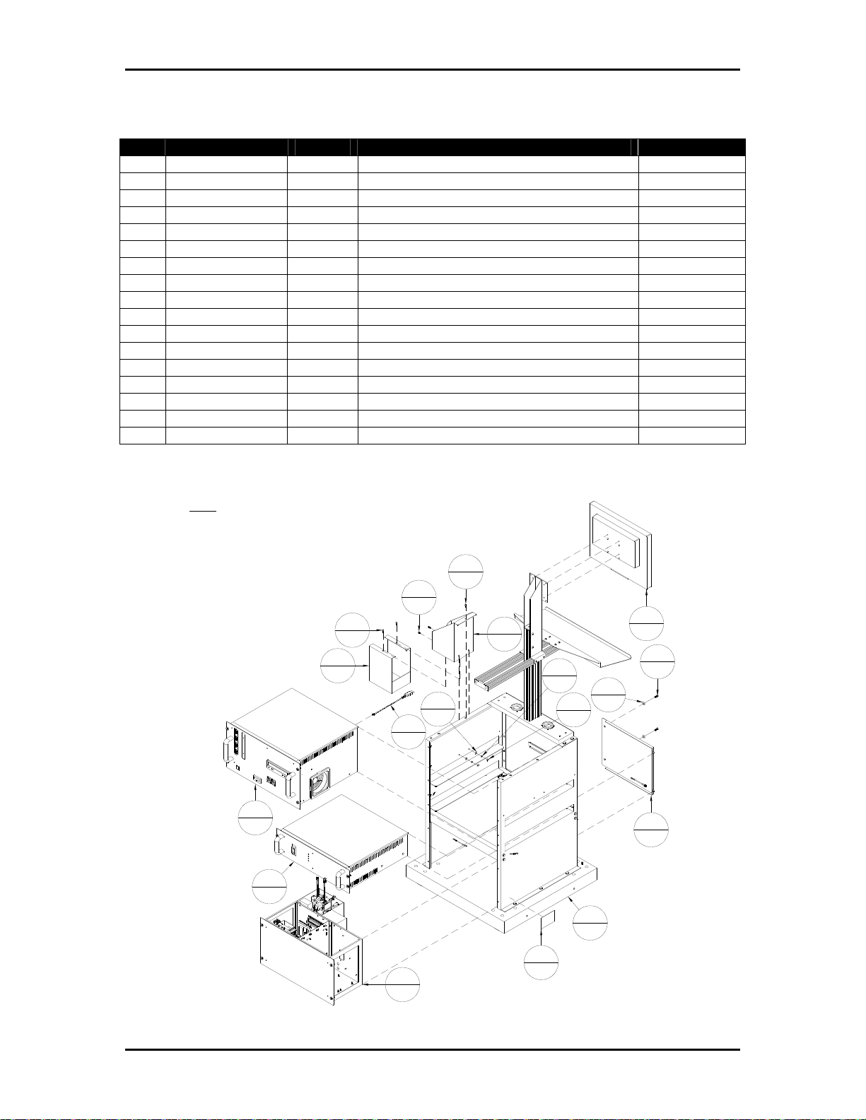
Appendix B Ink Specific Drawings Page B-3
Table B-3: BK705UU – Controller, BK705 Aurora
Item Part Number Quantity Description Reference
1 404050 2 Screw, FHCS, 10-32 UNF x ¾”
2 404520 4 Screw, BHCS, 10-32 UNF x 3/8”
3 405520 1 Screw, BHCS, ¼-20 UNC x 3/8”
4 420008 8 Nut, 10-32 UNF
5 439009 8 Lockwasher, No. 10
6 440008 2 Washer, #10
7 9101627 1 Buskro Serial Number Label
8 9103285A 1 Dongle Assembly
9 9103315 2 Washer, Cup, 10-32 UNF Flat Head
10 9104907 1 Bracket, Ink Bottle, BK705
11 9104909 1 Spill Tray
12 9104913A 1 Cover Assembly, BK705
13 BK705-ST 1 Controller Stand, BK705 Appendix A
14 BK-IWM-2U 1 Inkwell Module, 2-Channel Aurora Page B-6
15 BK-MON-LCD17 1 Monitor, 17” LCD
16 BK-PCM-8 1 Module, Computer Assembly Appendix A
17 BK-PSM-4A 1 Module, Power Supply, Atlas/Aurora Appendix C
Figure B-3: BK705UU – Controller, BK705 Atlas Aurora
NOTE:
BK-PSM-4A IS SHOWN FOR REFERENCE. IT IS
INCLUDED FOR THE NORTH AMERICAN CASE
(115VAC). FOR THE REST OF THE WORLD
(200/230VAC), BK-PSM-4A-WD IS USED.
11
1
16
1
17
1
2
4
2
4
8
1
3
1
10
1
6
2
15
1
1
5
2
9
2
4
2
2
12
1
13
1
7
14
1
1
Buskro Ltd. BK705
Page 73
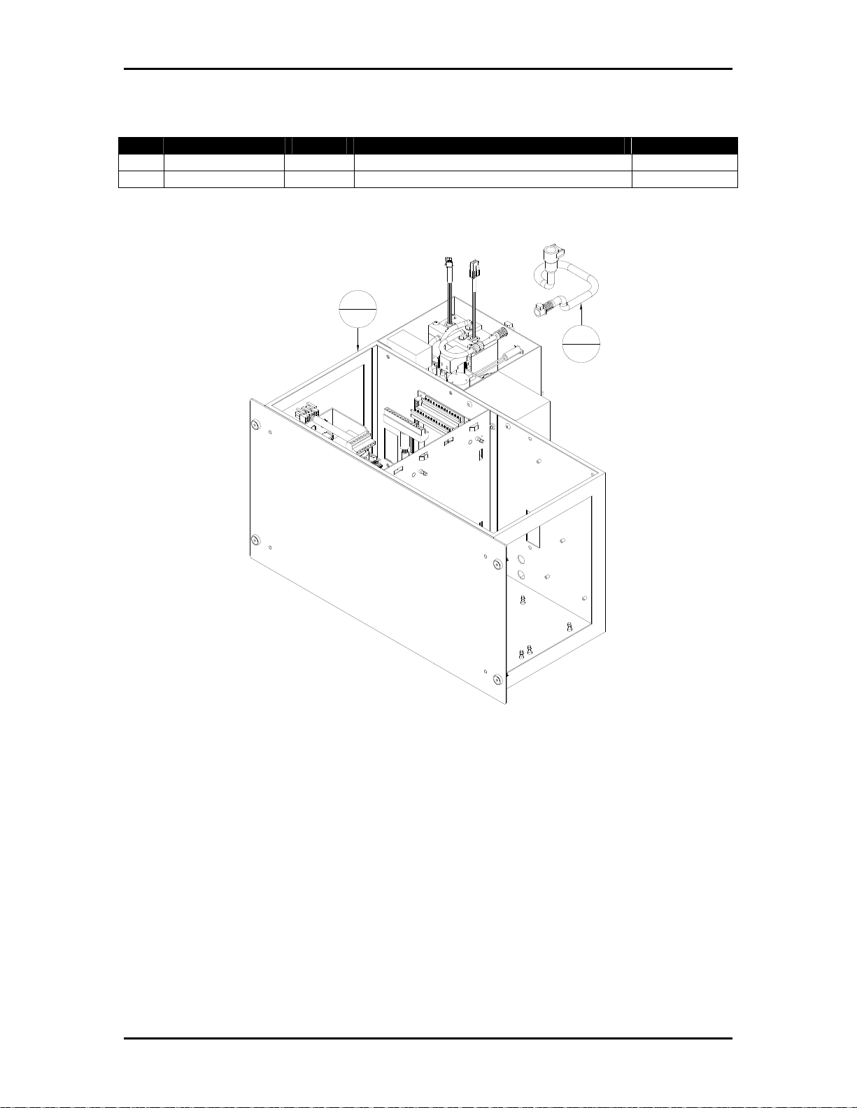
Appendix B Ink Specific Drawings Page B-4
Table B-4: BK-IWM-2A – Inkwell Module, 2-Channel Monet
Item Part Number Quantity Description Reference
1 9102132A 1 Bottle Coupling Assembly, Monet Page B-12
2 9103767A 1 Inkwell Module, 2-Channel Atlas (Solvent) Page B-23
Figure B-4: BK-IWM-2A – Inkwell Module, 2-Channel Monet
2
1
1
1
Buskro Ltd. BK705
Page 74
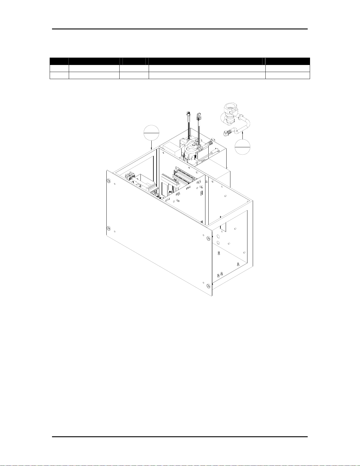
Appendix B Ink Specific Drawings Page B-5
Table B-5: BK-IWM-2C – Inkwell Module, 2-Channel Cezanne
Item Part Number Quantity Description Reference
1 9103767A 1 Inkwell Module, 2-Channel Atlas (Solvent) Page B-23
2 9103910A 1 Bottle Coupling Assembly, Cezanne Page B-28
Figure B-5: BK-IWM-2C – Inkwell Module, 2-Channel Cezanne
1
1
2
1
Buskro Ltd. BK705
Page 75
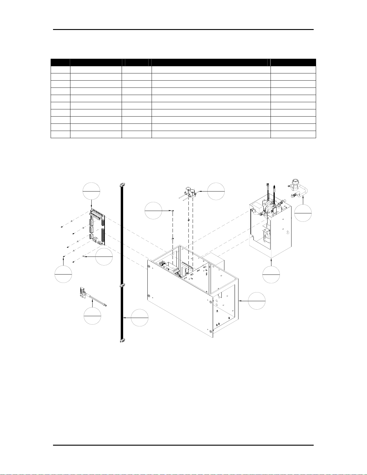
Appendix B Ink Specific Drawings Page B-6
Table B-6: BK-IWM-2U – Inkwell Module, 2-Channel Aurora
Item Part Number Quantity Description Reference
1 401310 5 Screw, PHMS, 4-40 UNC x ¼”
2 404510 3 Screw, BHCS, 10-32 UN x ¼”
3 440530 5 Washer, #6, Nylon
4 606052A 1 Cable, Atlas Power Support
5 9100969 1 Board, Atlas System Support
6 9103484A 1 Cable, System Communication
7 9103680A 1 Universal Enclosure Assembly Page B-18
8 9103683A 2 Solenoid Valve Assembly Page B-19
9 9103776A 1 Ink Delivery Module, BK705 Aurora Page B-24
10 9104497A 1 Bottle Coupling Assembly, Aurora Page B-29
Figure B-6: BK-IWM-2U – Inkwell Module, 2-Channel Aurora
5
1
2
3
3
5
1
5
4
1
6
1
8
2
10
1
9
1
7
1
Buskro Ltd. BK705
Page 76
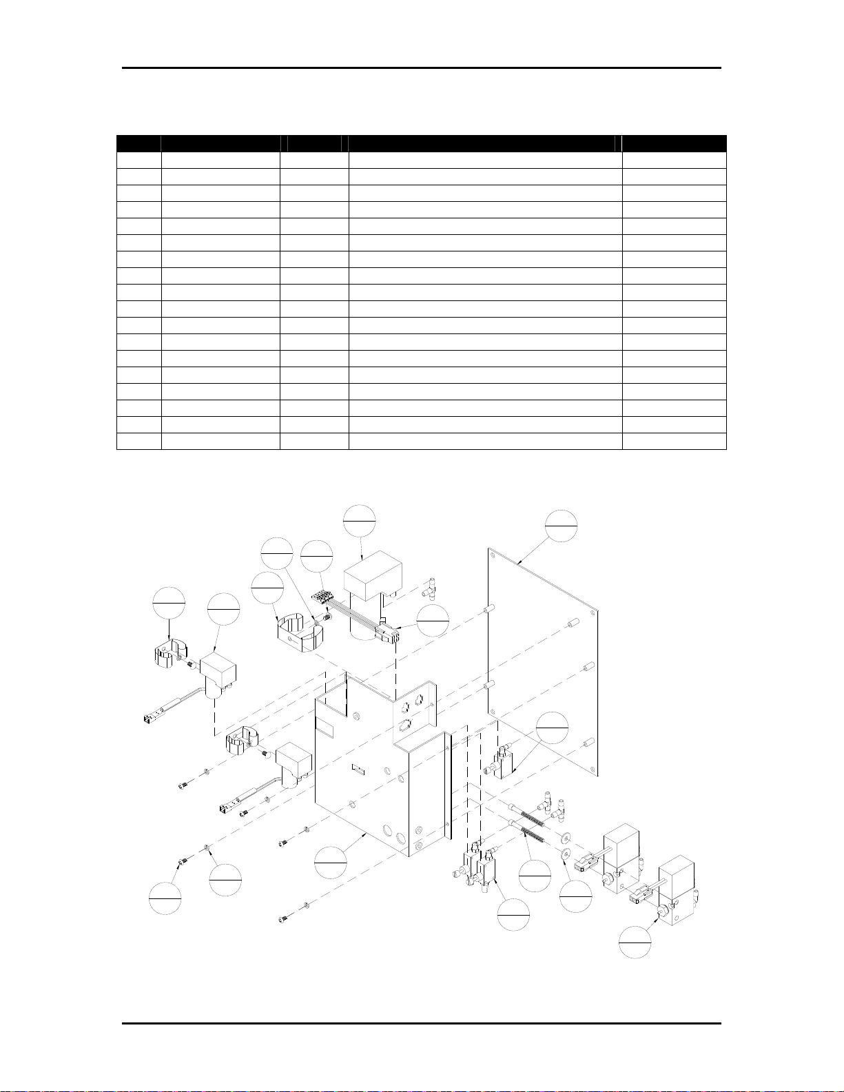
Appendix B Ink Specific Drawings Page B-7
Table B-7: BK-PVM-700 – Pressure Regulator, 2-Channel
Item Part Number Quantity Description Reference
1 402310 5 Screw, PHMS, 6-32 UNC x ¼”
2 403310 3 Screw, PHMS, 8-32 UNC x ¼”
3 439005 3 Lockwasher, No. 8
4 439006 5 Lockwasher, No. 6
5 440006 2 Washer, No. 8, ½” OD x 0.05” Thick
6 9100148A 2 Solenoid Valve Assembly, 3-Way
7 9100472 1 Tubing, Silicone, ¼” OD x 1/8” ID
8 9100921 1 Pressure Pump
9 9100971 1 Gripper Clip
10 9101290 4 Fitting, Tee, 1/8” ID
11 9102618A 1 Cable, Triple 12VDC
12 9102715 2 Gripper Clip, 3/8” – 5/8”
13 9102960A 2 Flow Control, Meniscus Vacuum Page B-14
14 9103020A 1 Flow Control Assembly, Purge Pressure Page B-15
15 9103198 2 Screw, SHCS, 8-32 UNC x 1-3/4”
16 9103473A 2 Meniscus Pump Assembly
17 9103634 1 Bracket, Mounting
18 9103635 1 Plate, Mounting
Figure B-7: BK-PVM-700 – Pressure Regulator, 2-Channel
8
1
3
2
3
3
9
12
2
1
5
16
2
4
5
1
11
1
17
1
18
1
14
1
15
2
5
13
2
2
6
2
Buskro Ltd. BK705
Page 77
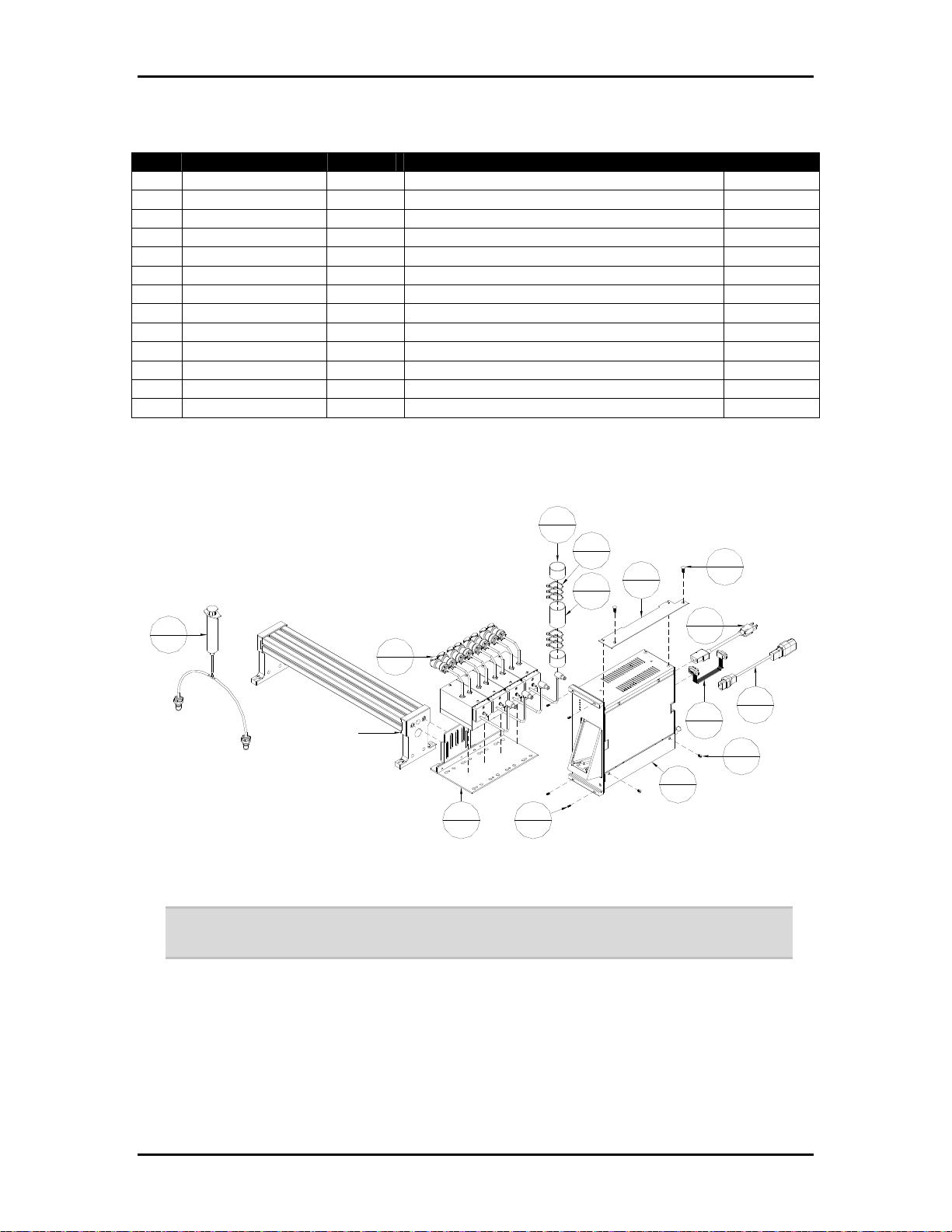
Appendix B Ink Specific Drawings Page B-8
Table B-8: 705-IDM4H-15NA - Apollo IDM, 4" BK705, 15', N. America
Item Part Number Quantity Description Reference
1 404510 2 Screw, BHCS, 10-32 UNF x 1/4"
2 405530 2 Screw, BHCS, 1/4-20 UNC x 1/2"
3 606322 1 Cord, Set, 10A/125VAC, 90", N.A., IEC
4 615140 6 Lashing Tie, Small
5 9101776 1 Sleeving, Braided, Expandable, 166"
6 9102603 2 Shrink Wrap, 1 1/2" OD, 1/2" ID. 2"
7 9103243A 1 HP Regulator Mount Assembly
8 9103565A 1 Cable, Ribbon, DB9 Male To Female, 50"
9 9104511 1 Cord, Set, 10A/250V, 2m, IEC-IEC
10 9104533 1 Bracket, BK705 IDM Mount
11 BK-BULKPRIME 1 Syringe Assembly, Apollo Bulk Ink
12 BK-BULKREG-15 4 Regulator Module, Apollo, 15'
13 BK-IDM-4H 1 Module, Apollo Ink Delivery, 4-Channel
Figure B-8: 705-IDM4H-15NA – Apollo IDM, 4" BK705, 15', N. America
7
2
5
6
11
6
1
12
1
BRIDGE SHOWN
FOR REFERENCE
13
4
8
1
1
4
1
4
1
9
1
14
1
Note: Power cord 9104511 is used with the optional stand (BK705-ST). Otherwise, use
606322.
3
2
10
1
2
2
Buskro Ltd. BK705
Page 78
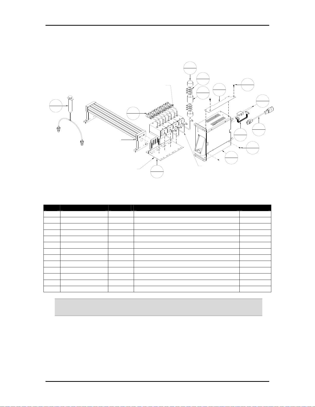
Appendix B Ink Specific Drawings Page B-9
Figure B-9: 705-IDM4H-15WD – Apollo IDM, 4" BK705, 15', World
5
2
3
FOR BRIDGE LENGTHS OF 22" OR LESS,
CUT 24" OFF THE TUBE BEFORE
INSTALLING THE CONNECTOR
11
1
BRIDGE SHOWN
FOR REFERENCE
MOUNT THE REGULATOR
SO THAT THE BOTTOM IS
1.0 TO 2.0" ABOVE THE
BOTTOM OF THE PRINTHEAD
12
4
6
1
6
4
1
10
1
13
1
USE THE BRAIDED SLEEVING (9101776)
TO TIE TUBES TOGETHER. LEAVE 7" OF
THE TUBING EXPOSED ON EACH END.
2
2
7
1
9
8
1
1
1
2
Table B-9: 705-IDM4H-15WD – Apollo IDM, 4" BK705, 15', World
Item Part Number Quantity Description Reference
1 404510 2 Screw, BHCS, 10-32 UNF x 1/4"
2 405530 2 Screw, BHCS, 1/4-20 UNC x 1/2"
3 615140 6 Lashing Tie, Small
4 9101776 1 Sleeving, Braided, Expandable, 166"
5 9102603 2 Shrink Wrap, 1 1/2" OD, 1/2" ID. 2"
6 9103243A 1 HP Regulator Mount Assembly
7 9103256 1 Cord, 10A/250VAC, 3m, Harmonized, IEC
8 9103565A 1 Cable, Ribbon, DB9 Male To Female, 50"
9 9104511 1 Cord, Set, 10A/250V, 2m, IEC-IEC
10 9104533 1 Bracket, BK705 IDM Mount
11 BK-BULKPRIME 1 Syringe Assembly, Apollo Bulk Ink
12 BK-BULKREG-15 4 Regulator Module, Apollo, 15'
13 BK-IDM-4H 1 Module, Apollo Ink Delivery, 4-Channel
Note: Power cord 9104511 is used with the optional stand (BK705-ST). Otherwise, use
9103256.
Buskro Ltd. BK705
Page 79
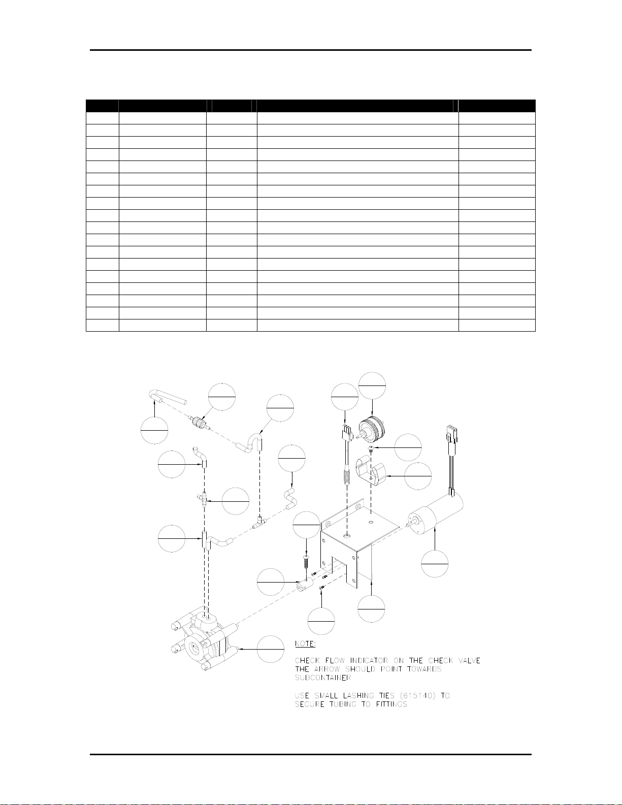
Appendix B Ink Specific Drawings Page B-10
Table B-10: 9101767A – Pumping Station Assembly, Atlas (Monet & Cezanne)
Item Part Number Quantity Description Reference
1 401310 3 Screw, PHMS, 4-40 UNC x ¼”
2 404510 1 Screw, BHCS, 10-32 UNF x ¼”
3 404550 1 Screw, BHCS, 10-32 UNF x ¾”
4 615140 8 Lashing Tie, Small
5 630004A 1 Cycle Proximity Switch Assembly
6 9100149A 1 Filter Holder Assembly
7 9100876 1 Coupling, 0.5” DIA
8 9100931 1 Peristaltic Pump Head
9 9100936A 1 Gearmotor Assembly
10 9100971 1 Gripper Clip
11 9101290 2 Fitting, Tee, 1/8” ID
12 9101700 1 Check Valve, 1/8” ID
13 9101767 1 Bracket, Pumping Station
14 9102116 1 Tubing, Pharmed, ¼” x 1/8”, 9” Lg.
15 9102116 1 Tubing, Pharmed, ¼” x 1/8”, 4” Lg.
16 9102116 1 Tubing, Pharmed, ¼” x 1/8”, 1.5” Lg.
17 9102116 1 Tubing, Pharmed, ¼” x 1/8”, 1.25” Lg.
18 9102116 1 Tubing, Pharmed, ¼” x 1/8”, 1.25” Lg.
Figure B-10: 9101767A – Pumping Station Assembly, Atlas (Monet & Cezanne)
6
1
12
1
15
1
16
1
11
2
14
1
17
1
18
1
3
1
7
1
8
1
5
1
2
1
10
1
9
1
13
1
3
1
Buskro Ltd. BK705
Page 80
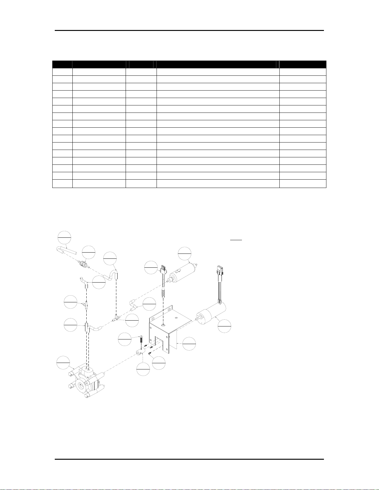
Appendix B Ink Specific Drawings Page B-11
Table B-11: 9101780A – Pumping Station Assembly, Aurora
Item Part Number Quantity Description Reference
1 401310 3 Screw, PHMS, 4-40 UNC x ¼”
2 404550 1 Screw, BHCS, 10-32 UNF x ¾”
3 615140 8 Lashing Tie, Small
4 630004A 1 Cycle Proximity Switch Assembly
5 9100876 1 Coupling, 0.5” DIA
6 9100931 1 Peristaltic Pump Head
7 9100936A 1 Gearmotor Assembly
8 9101290 2 Fitting, Tee, 1/8” ID
9 9101700 1 Check Valve, 1/8” ID
10 9101767 1 Bracket, Pumping Station
11 9102116 1 Tubing, Pharmed, ¼” x 1/8”, 9” Lg.
12 9102116 1 Tubing, Pharmed, ¼” x 1/8”, 4” Lg.
13 9102116 1 Tubing, Pharmed, ¼” x 1/8”, 1.5” Lg.
14 9102116 1 Tubing, Pharmed, ¼” x 1/8”, 1.25” Lg.
15 9102116 1 Tubing, Pharmed, ¼” x 1/8”, 1.25” Lg.
16 9103390A 1
Filter, Assembly, 10 μm
Figure B-11: 9101780A – Pumping Station Assembly, Aurora
Page B-15
12
1
9
1
8
2
11
1
6
1
14
1
13
1
8
2
2
1
4
1
15
1
1
3
5
1
16
1
10
1
NOTE:
CHECK FLOW INDICATOR ON THE CHECK VALVE
THE ARROW SHOULD POINT TOWARDS
SUBCONTAINER
USE SMALL LASHING TIES (615140) TO SECURE
TUBING TO FITTINGS
CHECK FLOW INDICATOR ON 10 MICRON FILTER
THE ARROW SHOULD POINT TOWARDS INK
DISCHARGE
COVER PHARMED TUBING WITH SHRINK WRAP
(EXCEPT INSIDE PUMP). HEAT SHRINK TUBING
BEFORE APPLYING INK. USE 609003 (3/8" ID).
7
1
Buskro Ltd. BK705
Page 81
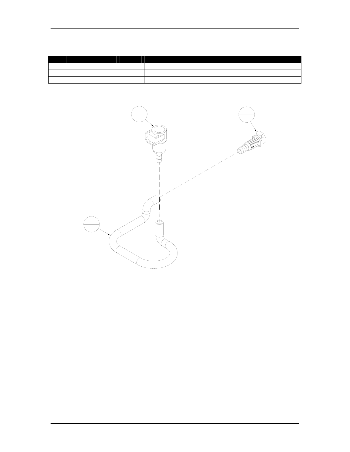
Appendix B Ink Specific Drawings Page B-12
Table B-12: 9102132A – Bottle Coupling Assembly, Monet
Item Part Number Quantity Description Reference
1 9100967 1 Coupling Body, Puncture Seal, 3/8”
2 9102132 1 Tubing, Pharmed, 3/8 x ¼”, 13” Lg.
3 9103910 1 Coupling Body, ¼” ID, Shutoff
Figure B-12: 9102132A – Bottle Coupling Assembly, Monet
1
1
2
1
3
1
Buskro Ltd. BK705
Page 82
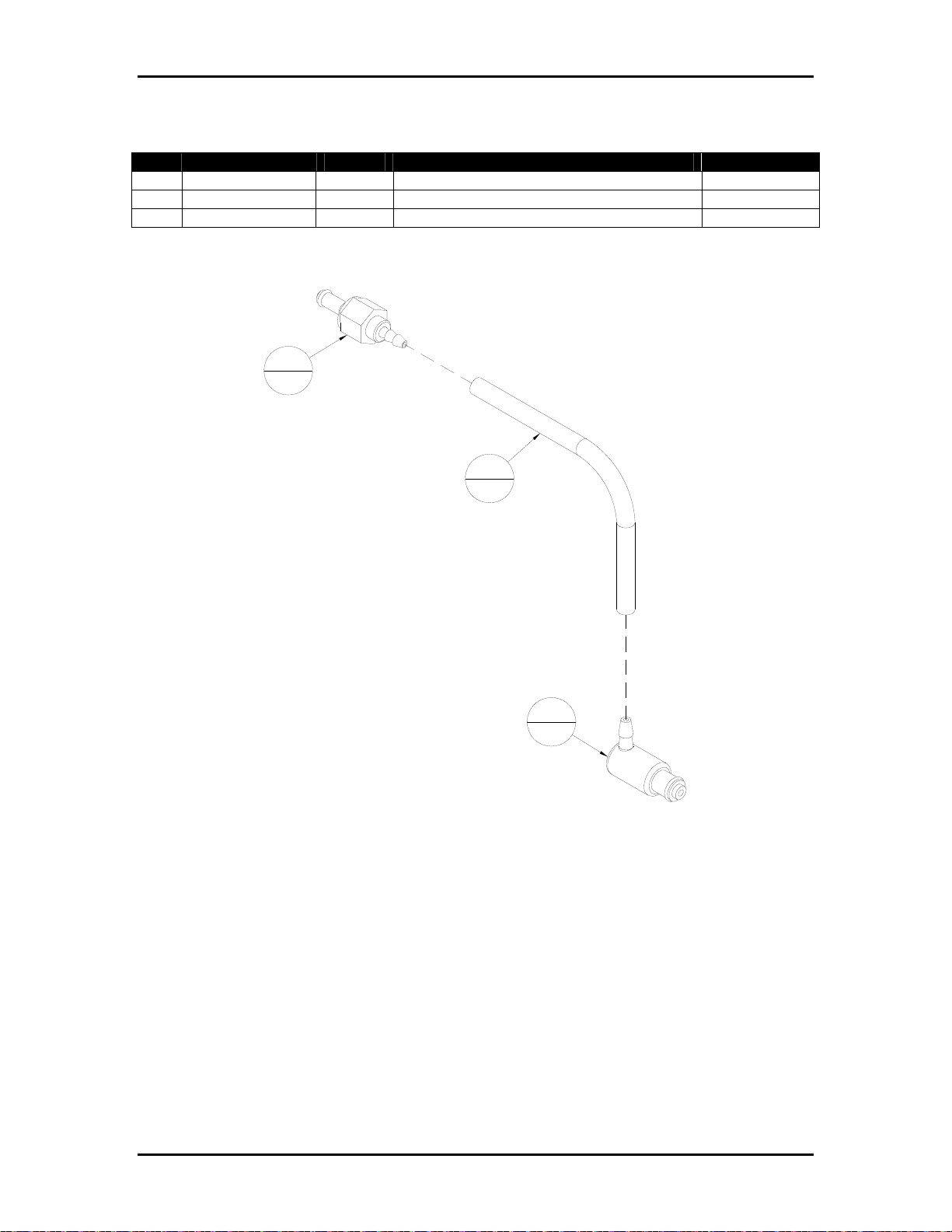
Appendix B Ink Specific Drawings Page B-13
Table B-13: 9102147A – Ink Line Assembly
Item Part Number Quantity Description Reference
1 9101691 1 Coupling Insert, 1/8” ID, Inline, Hose Barb
2 9102116 1 Tubing, Pharmed, ¼ x 1/8”, 24” Lg.
3 9102148 1 Coupling Insert, Elbow, 1/8” ID
Figure B-13: 9102147A – Ink Line Assembly
1
1
2
1
3
1
Buskro Ltd. BK705
Page 83
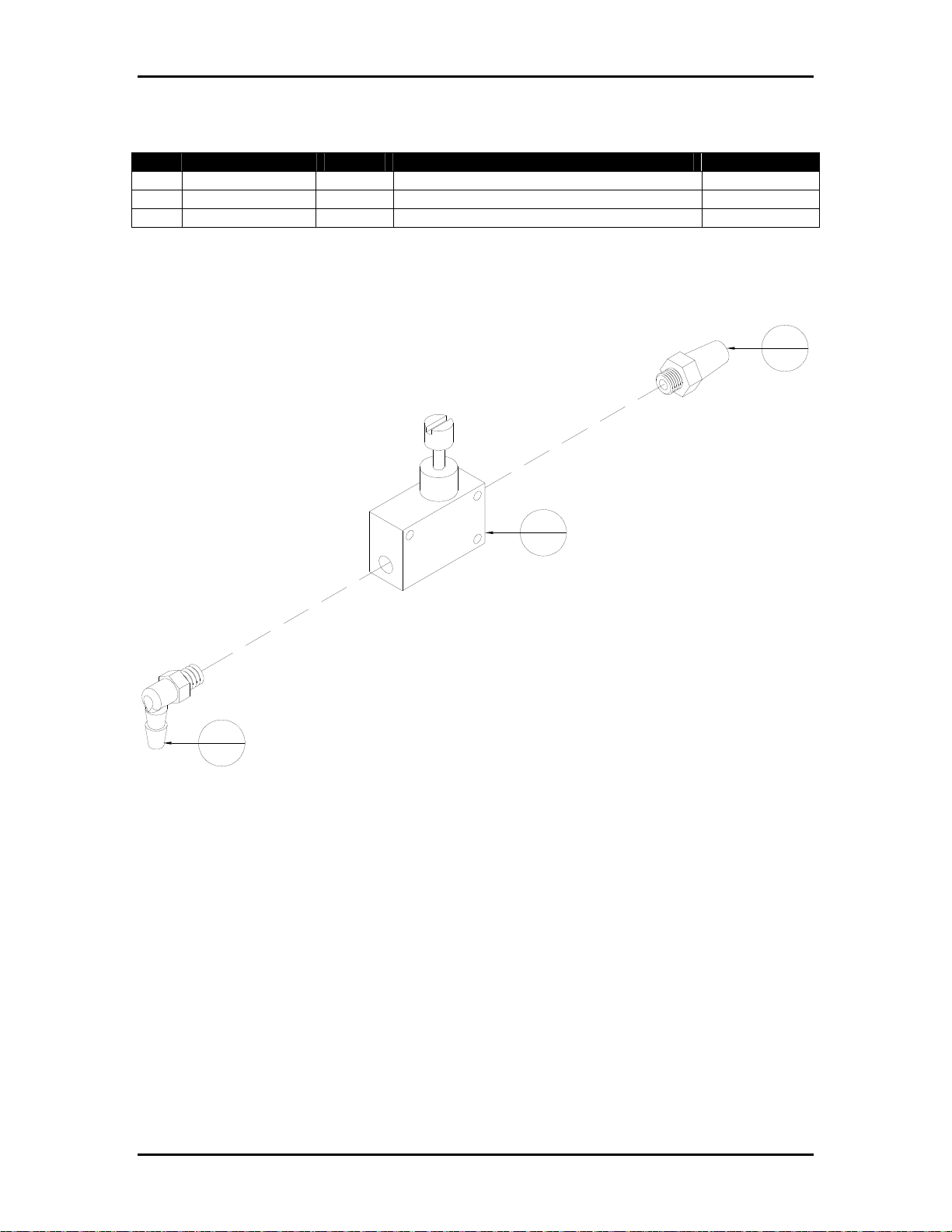
Appendix B Ink Specific Drawings Page B-14
Table B-14: 9102960A – Flow Control, Meniscus Vacuum
Item Part Number Quantity Description Reference
1 9102575 1 Filter, Bronze/Steel
2 9102960 1 Valve, Flow Control, 10-32 UNF
3 9103020 1 Fitting, 10-32 UNF, Elbow, 1/8” ID
Figure B-14: 9102960A – Flow Control, Meniscus Vacuum
1
1
2
1
3
1
Buskro Ltd. BK705
Page 84
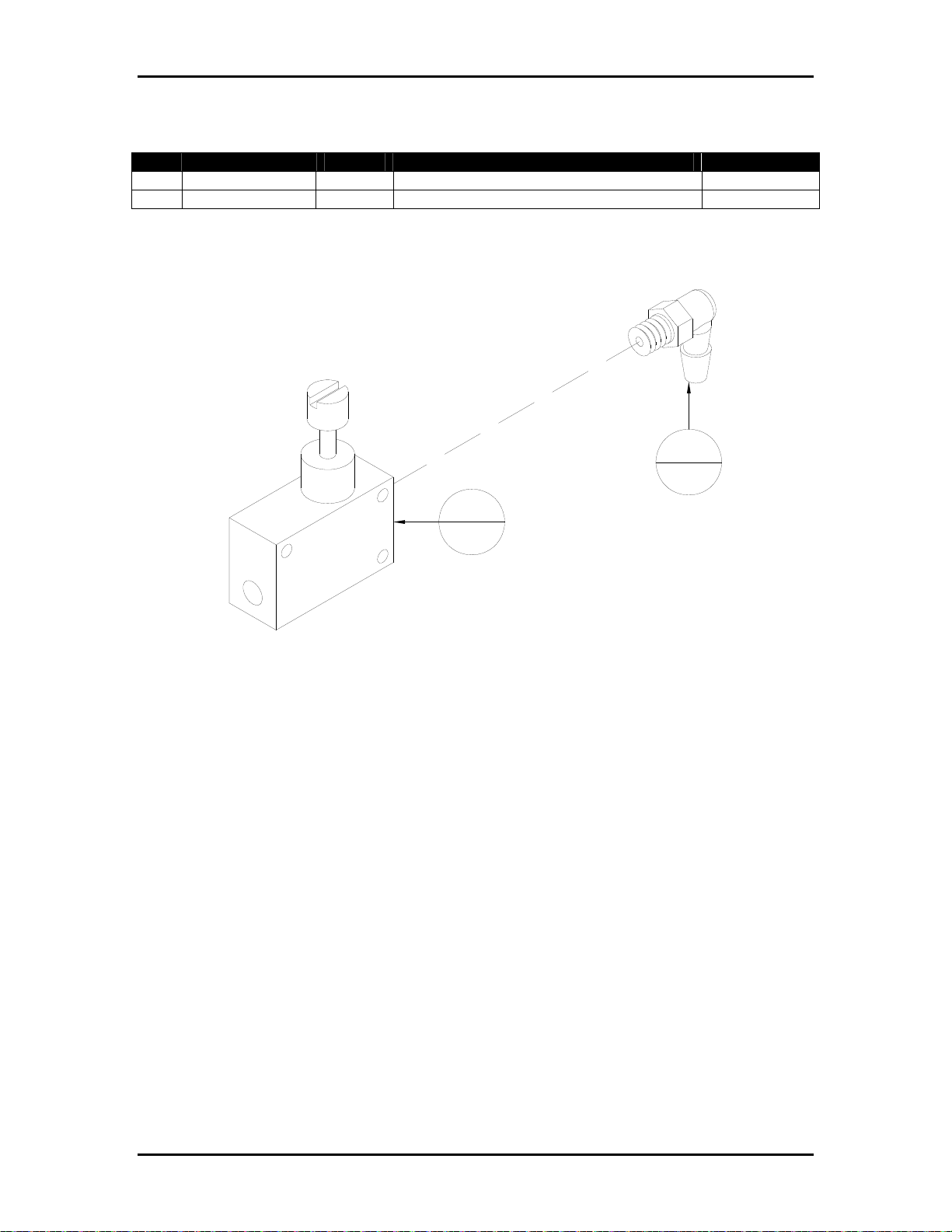
Appendix B Ink Specific Drawings Page B-15
Table B-15: 9103020A – Flow Control, Purge Pressure
Item Part Number Quantity Description Reference
1 9102960 1 Valve, Flow Control, 10-32 UNF
2 9103020 1 Fitting, 10-32 UNF, Elbow, 1/8” ID
Figure B-15: 9103020A – Flow Control, Purge Pressure
2
1
1
1
Buskro Ltd. BK705
Page 85
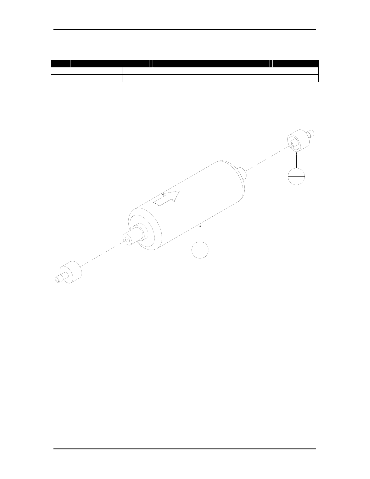
Appendix B Ink Specific Drawings Page B-16
Table B-16: 9103390A – Filter, Assembly, 10
μ
m
Item Part Number Quantity Description Reference
1 9103257 2 Luer, Male, 1/8” ID Tubing, Black
2 9103390 1
Figure B-16:
9103390A – Filter, Assembly, 10 μm
Filter, 10 μm, UV
1
2
2
1
Buskro Ltd. BK705
Page 86
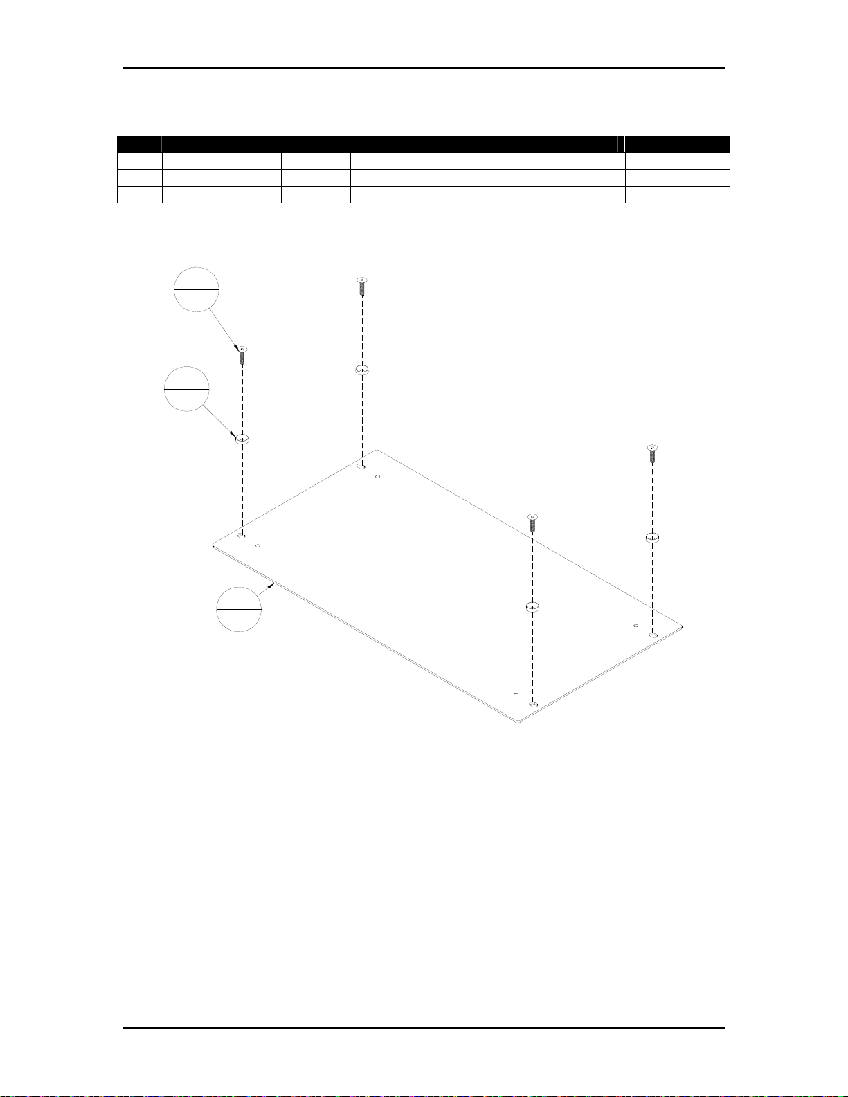
Appendix B Ink Specific Drawings Page B-17
Table B-17: 9103677A – Cover, Blank 6U
Item Part Number Quantity Description Reference
1 404050 4 Screw, FHCS, 10-32 UNF x ¾”
2 9103315 4 Washer, Cup, 10-32 UNF Flat Head
3 9103677 1 Cover, Blank 6U
Figure B-17: 9103677A – Cover, Blank 6U
1
4
2
4
3
1
Buskro Ltd. BK705
Page 87

Appendix B Ink Specific Drawings Page B-18
Table B-18: 9103680A – Universal Enclosure Assembly
Item Part Number Quantity Description Reference
1 404510 5 Screw, BHCS, 10-32 UNF x ¼”
2 420008 8 Nut, 10-32 UNF
3 439008 1 Lockwasher, No. 10, External Tooth
4 439009 11 Lockwasher, No. 10
5 606311A 1 Cable, System Support Interface
6 609111 2 Terminal, Ring, #10, 16-14 AWG, Blue
7 9100197A 2 Cable, HDC, 21” Lg.
8 9100206A 1 Cable, Pressure Regulator
9 9100994 2 Board, Head Drive Circuit (HDC)
10 9102681 1 Wire, #14, Green/Yellow, 6 “ Lg.
11 9103677A 1 Cover, Blank 6U Page B-17
12 9103680 1 Chamber, Electronics Module
13 9103762 1 Bracket, Chamber Mediate
14 9103764A 1 Power Distribution Box Assembly Page B-20
15 9103810 4 Knurled Brass Thumb Nut, 10-32 UNF
16 9104380 1 Board, System Support CPU (SSB II)
17 BK-PVM-700 1 Pressure Regulator, 2 Channel Page B-7
Figure B-18: 9103680A – Universal Enclosure Assembly
4
11
16
13
1
2
8
4
4
11
2
8
2
8
14
11
2
8
1
5
4
11
1
5
4
11
15
4
1
1
5
1
10
1
3
1
6
2
8
1
17
1
11
1
7
2
12
1
9
2
Buskro Ltd. BK705
Page 88
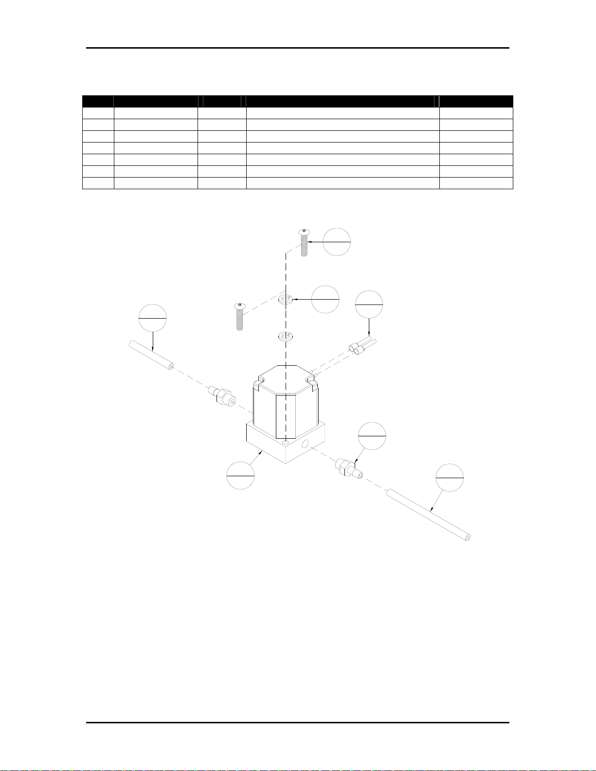
Appendix B Ink Specific Drawings Page B-19
Table B-19: 9103683A – Solenoid Valve Assembly
Item Part Number Quantity Description Reference
1 401330 2 Screw, PHMS, 4-40 UNC x ½”
2 439004 2 Lockwasher, No. 4
3 9100170 1 Tubing, Viton, 1/8 x 1/16”, 12” Lg.
4 9100170 1 Tubing, Viton, 1/8 x 1/16”, 23” Lg.
5 9101583 2 Fitting, Tube 1/16” ID
6 9103540 2 Ferrule, #24 AWG, Light Blue
7 9103683 1 Solenoid Valve, 2-Way, 12 VDC
Figure B-19: 9103683A – Solenoid Valve Assembly
1
2
4
1
7
1
Note: Use silicone for thread sealing.
Cut wires to reach terminal blocks.
Letter "H" towards pressure regulator -
air source.
2
2
6
2
5
2
3
1
Buskro Ltd. BK705
Page 89
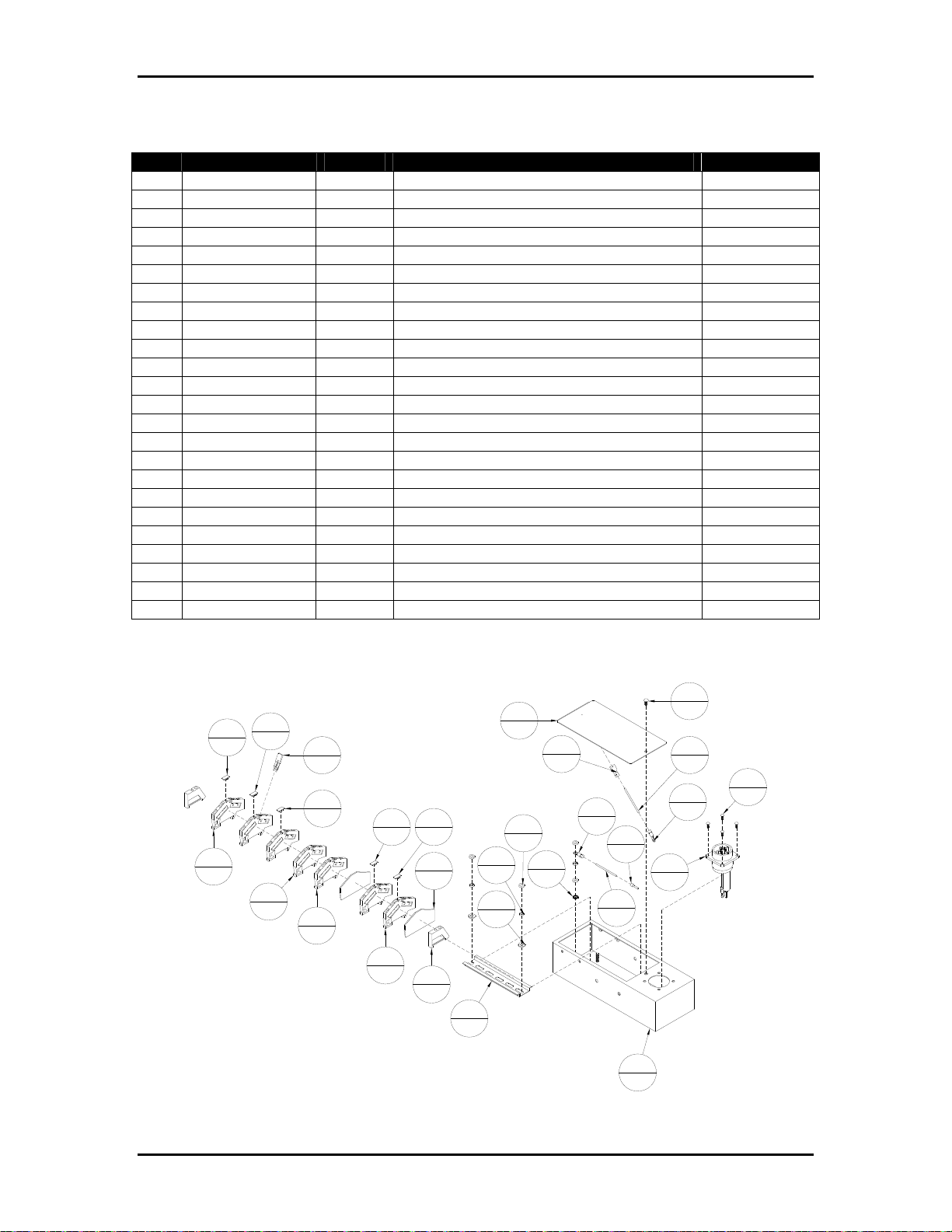
Appendix B Ink Specific Drawings Page B-20
Table B-20: 9103764A – Power Distribution Box Assembly
Item Part Number Quantity Description Reference
1 402320 4 Screw, PHMS, 6-32 UNC x 3/8”
2 404320 1 Screw, PHMS, 10-32 UNF x 3/8”
3 420008 4 Nut, 10-32 UNF
4 439008 1 Lockwasher, No. 10, External Tooth
5 439009 3 Lockwasher, No. 10
6 440008 2 Washer, #10 ID
7 609110 1 Connector, Push-On, 16-14 AWG, Blue
8 609111 2 Terminal, Ring, #10, 16-14 AWG, Blue
9 615021 1 T-Rail, DIN, 5.5” Lg.
10 9102050 1 Terminal Marker, WS 12/6, L
11 9102051 1 Terminal Marker, WS 12/6, N
12 9102052 2 Terminal Marker, WS 12/6, 12VDC
13 9102053 1 Terminal Marker, WS 12/6, 170VDC
14 9102681 1 Wire, #14, Green/Yellow, 8” Lg.
15 9102681 1 Wire, #14, Green/Yellow, 5” Lg.
16 9103433 1 Ferrule, #14 AWG, Blue
17 9103436 5 Terminal Block, Z-Roofstyle
18 9103437 2 Terminal Block, Z-Roofstyle, Ground
19 9103438 2 End Plate
20 9103439 1 Cross-Connection
21 9103439A 1 Cable, Power Distribution
22 9103442 2 End Bracket
23 9103764 1 Bracket, Power Distribution
24 9103767 1 Cover, Power Box
Figure B-20: 9103764A – Power Distribution Box Assembly
24
12
13
17
5
2
1
18
2
20
1
12
2
18
2
17
10
11
1
1
19
2
5
22
2
9
1
1
7
1
3
4
5
3
6
2
4
1
2
1
14
1
1
8
8
2
16
1
15
1
23
1
2
21
1
4
Buskro Ltd. BK705
Page 90
Appendix B Ink Specific Drawings Page B-21
Table B-21: 9103766A – Ink Delivery Module, BK705 Atlas (Monet & Cezanne)
Item Part Number Quantity Description Reference
1 404510 3 Screw, BHCS, 10-32 UNF x ¼”
2 404520 2 Screw, BHCS, 10-32 UNF x 3/8”
3 439009 4 Lockwasher, No. 10
4 615140 12 Lashing Tie, Small
5 640301A 1 Cable, IDS Drive
6 9100472 1 Tubing, Silicone, ¼” OD x 1/8” ID, 4” Lg.
7 9100472 2 Tubing, Silicone, ¼” OD x 1/8” ID, 3” Lg.
8 9100472 1 Tubing, Silicone, ¼” OD x 1/8” ID, 5” Lg.
9 9100921 1 Lung Vacuum Pump
10 9100921A 1 Adapter Cable Assembly
11 9100962 2 Coupling, Hose Barb, Panel Mount, 1/16”
12 9100971 1 Gripper Clip
13 9101582 2 Fitting, 10-32 Thread to Tube 1/8” ID
14 9101692 4 Coupling Body, 1/8” ID Tubing
15 9101767A 1 Pumping Station Assembly Page B-10
16 9102116 2 Tubing, Pharmed, ¼ x 1/8”, 3” Lg.
17 9102116 1 Tubing, Pharmed, ¼ x 1/8”, 8” Lg.
18 9102147A 1 Ink Line Assembly Page B-13
19 9103712 2 Fitting, Y Tube-to-tube, 1/8 ID, Nylon
20 9103766 1 Chamber, Ink Delivery, 2-Channel
21 9103784A 1 Ink Reservoir Assembly, BK705 Page B-26
22 9104430A 1 Cable, BK705 Dual Chamber Adapter
23 9104610 2 Coupling, Panel Mount, 1/8” ID Shutoff
Buskro Ltd. BK705
Page 91
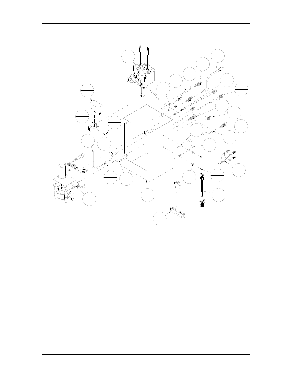
Appendix B Ink Specific Drawings Page B-22
Figure B-21: 9103766A – Ink Delivery Module, BK705 Atlas (Monet & Cezanne)
20
1
15
2
9
1
11
1
8
1
1
3
7
2
18
2
7
2
16
1
13
4
13
4
12
2
3
4
17
1
2
2
23
2
13
4
22
2
13
4
15
6
1
2
21
1
3
1
19
14
1
1
Note:
Lashing ties to all barbed ink line fittings.
Apply teflon tape on threads on 10-32 UNF barb
fittings.
10
1
5
1
Buskro Ltd. BK705
Page 92
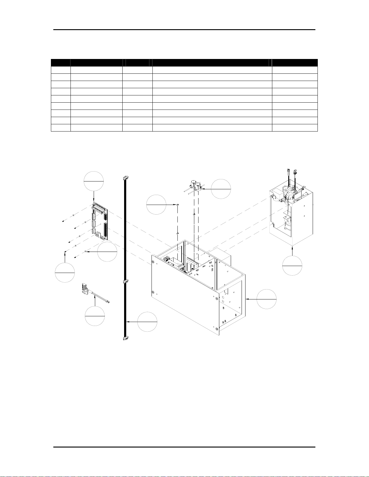
Appendix B Ink Specific Drawings Page B-23
Table B-22: 9103767A – Inkwell Module, 2-Channel Atlas (Monet & Cezanne)
Item Part Number Quantity Description Reference
1 401310 5 Screw, PHMS, 4-40 UNC x ¼”
2 404510 3 Screw, BHCS, 10-32 UNF x ¼”
3 440530 5 Washer, #6, Nylon
4 606052A 1 Cable, Atlas Power Support
5 9100969 1 System Support Board, Atlas
6 9103484A 1 Cable, System Communication
7 9103680A 1 Universal Enclosure Assembly Page B-18
8 9103683A 2 Solenoid Valve Assembly Page B-19
9 9103766A 1 Ink Delivery Module, BK705 Atlas Page B-21
Figure B-22: 9103767A – Inkwell Module, 2-Channel Atlas (Monet & Cezanne)
5
1
8
2
2
3
3
5
9
1
5
7
1
4
1
6
1
1
Buskro Ltd. BK705
Page 93
Appendix B Ink Specific Drawings Page B-24
Table B-23: 9103776A – Ink Delivery Module, BK705 Aurora
Item Part Number Quantity Description Reference
1 404510 3 Screw, BHCS, 10-32 UNF x ¼”
2 404520 2 Screw, BHCS, 10-32 UNF x 3/8”
3 439009 4 Lockwasher, No. 10
4 609003 1 Shrink Wrap, 3/8” ID, 32” Total
5 615140 12 Lashing Tie, Small
6 640301A 1 Cable, IDS Drive
7 9100472 1 Tubing, Silicone, ¼” OD x 1/8” ID, 4” Lg.
8 9100472 2 Tubing, Silicone, ¼” OD x 1/8” ID, 3” Lg.
9 9100472 1 Tubing, Silicone, ¼” OD x 1/8” ID, 5” Lg.
10 9100921 1 Lung Vacuum Pump
11 9100921A 1 Adapter Cable Assembly
12 9100962 2 Coupling, Hose Barb, Panel Mount, 1/16”
13 9100971 1 Gripper Clip
14 9101582 2 Fitting, 10-32 Thread to Tube 1/8” ID
15 9101780A 1 Pumping Station Assembly, Aurora Page B-11
16 9102116 2 Tubing, Pharmed, ¼ x 1/8”, 3” Lg.
17 9102116 1 Tubing, Pharmed, ¼ x 1/8”, 8” Lg.
18 9102147A 1 Ink Line Assembly Page B-13
19 9102625 4 Coupling, Panel Mount, ¼” OD Through
20 9102627 4 Plug, Body, EPDM O-Ring
21 9103712 2 Fitting, Y Tube-to-tube, 1/8 ID, Nylon
22 9103766 1 Chamber, Ink Delivery, 2-Channel
23 9103784A 1 Ink Reservoir Assembly, BK705 Page B-26
24 9104430A 1 Cable, BK705 Dual Chamber Adapter
25 9104610 2 Coupling, Panel Mount, 1/8” ID Shutoff
Buskro Ltd. BK705
Page 94
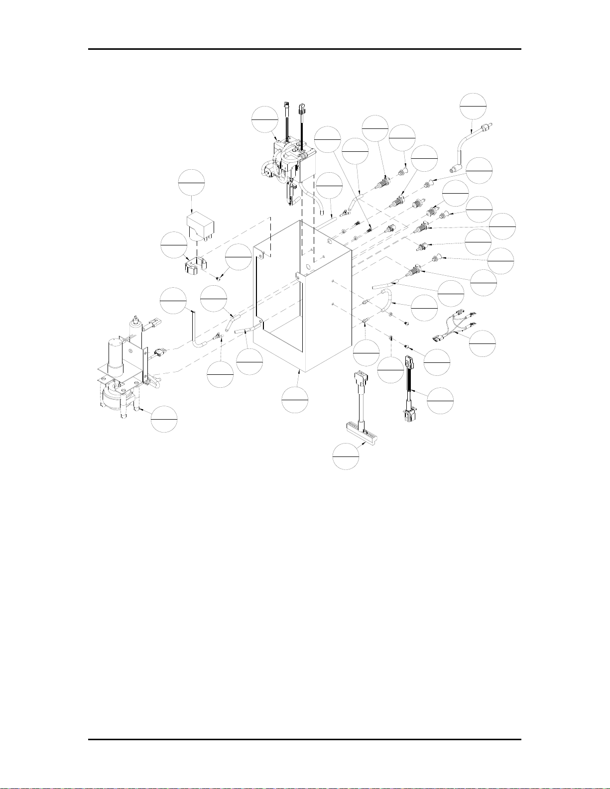
Appendix B Ink Specific Drawings Page B-25
Figure B-23: 9103776A – Ink Delivery Module, BK705 Aurora
18
23
1
2
2
10
1
13
1
9
1
1
3
8
2
17
1
19
4
20
16
2
4
19
4
7
1
1
20
4
12
2
20
4
19
4
25
2
20
4
19
16
2
4
8
21
15
1
2
2
Note: Shrink wrap all exposed ink tube lines,
including dual chamber sub-container tubes.
Lashing ties to all barbed ink line fittings.
24
14
2
3
4
22
1
6
Note: Apply teflon tape on threads
1
1
3
11
1
1
on 10-32 UNF barb fittings.
Buskro Ltd. BK705
Page 95

Appendix B Ink Specific Drawings Page B-26
Table B-24: 9103784A – Ink Reservoir Assembly, BK705
Item Part Number Quantity Description Reference
1 401330 2 Screw, PHMS, 4-40 UNC x ½”
2 404520 1 Screw, BHCS, 10-32 UNF x 3/8”
3 404530 3 Screw, BHCS, 10-32 UNF x ½”
4 404550 3 Screw, BHCS, 10-32 UNF x ¾”
5 439004 2 Lockwasher, No. 4
6 439009 7 Lockwasher, No. 10
7 615102 1 Tie Mount
8 615140 20 Lashing Tie, Small
9 615141 1 Lashing Tie, Large
10 9100149 1 Connector, 1/8” NPT, 1/8” ID
11 9100472 1 Tubing, Silicone, ¼” OD x 1/8” ID, 3” Lg.
12 9100472 1 Tubing, Silicone, ¼” OD x 1/8” ID, 2.5” Lg.
13 9100472 1 Tubing, Silicone, ¼” OD x 1/8” ID, 1.5” Lg.
14 9100472 1 Tubing, Silicone, ¼” OD x 1/8” ID, 1” Lg.
15 9100472 1 Tubing, Silicone, ¼” OD x 1/8” ID, 3” Lg.
16 9100877 1 O-Ring, 1-7/8 x 1-3/4 x 1/16, EPDM P.C.
17 9101290 1 Fitting, Tee, 1/8” ID
18 9102085 2 Connector, 1/8-27 NPT, 1/8” ID
19 9102116 1 Tubing, Pharmed, ¼ OD x 1/8” ID, 4.5” Lg
20 9102116 1 Tubing, Pharmed, ¼ OD x 1/8” ID, 1” Lg.
21 9102116 1 Tubing, Pharmed, ¼ OD x 1/8” ID, 5” Lg.
22 9102116 1 Tubing, Pharmed, ¼ OD x 1/8” ID, 5” Lg.
23 9104660 1 Reservoir, Ink/Air
24 9104661A 1 Reservoir Cover Assembly Page B-30
25 9104662A 1 Pump Assembly
26 9104671 1 Check Valve, 1/8” ID Barbed, 1 PSI
27 9104674 1 Check Valve, 1/8” ID Barbed, 4 PSI
28 9104711A 1 Solenoid Valve Assembly, 3-Way, N.O.
29 9104717 1 O-Ring, 1-1/8 x 1 x 1/16, EPDM P.C.
Buskro Ltd. BK705
Page 96
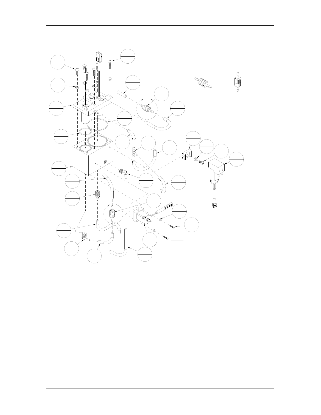
Appendix B Ink Specific Drawings Page B-27
Figure B-24: 9103784A – Ink Reservoir Assembly, BK705
4
3
3
3
Note: Use teflon tape on one elbow, one
straight and one quick disconnect
connectors, 1/8-27 NPT threads.
Î
16
13
1
1
Î
20
1
27
1
A
17
1
18
2
26
1
6
7
24
1
29
1
23
1
11
1
10
1
B
15
1
19
1
Î
14
DETAIL A
1
5
2
Î
7
1
6
7
2
1
DETAIL B
25
1
1
22
1
28
18
2
12
1
1
21
1
Note: Small lashing ties 615140 to all tubes.
Shrink wrap ALL Pharmed tubing for Aurora
(UV) systems using 609003 (3/8" ID).
2
Buskro Ltd. BK705
Page 97
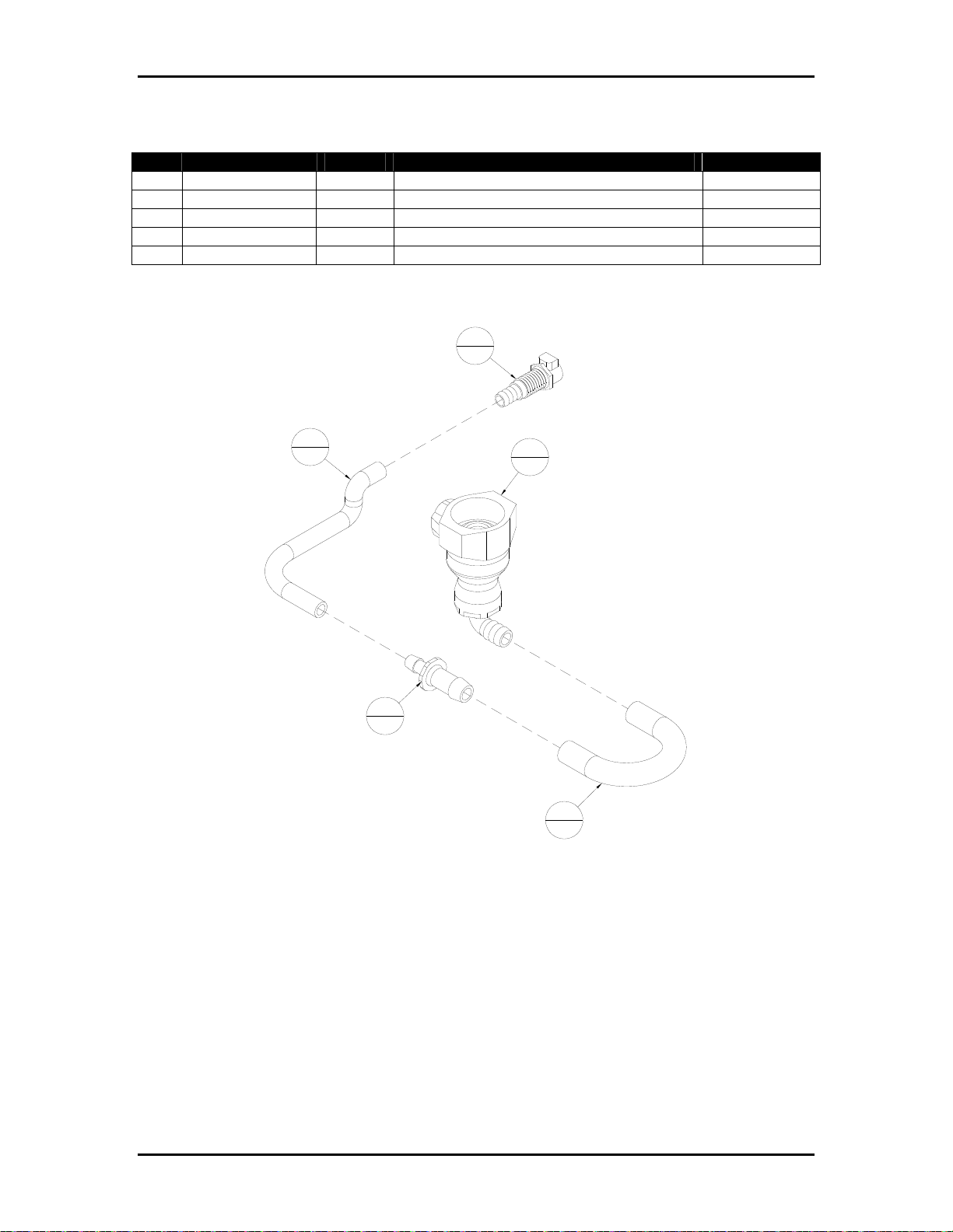
Appendix B Ink Specific Drawings Page B-28
Table B-25: 9103910A – Bottle Coupling Assembly, Cezanne
Item Part Number Quantity Description Reference
1 9102132 1 Tubing, Pharmed, 3/8” x ¼”, 10” Lg.
2 9103908 1 Tubing, Pharmed, ½” x 3/8”, 3” Lg.
3 9103909 1 Coupling, UDC Series, 3/8” ID, Elbow
4 9103910 1 Coupling, ¼” ID, Panel Mount, Shutoff
5 9103911 1 Fitting, 3/8 ID to ¼ ID
Figure B-25: 9103910A – Bottle Coupling Assembly, Cezanne
4
1
1
1
3
1
5
1
2
1
Buskro Ltd. BK705
Page 98
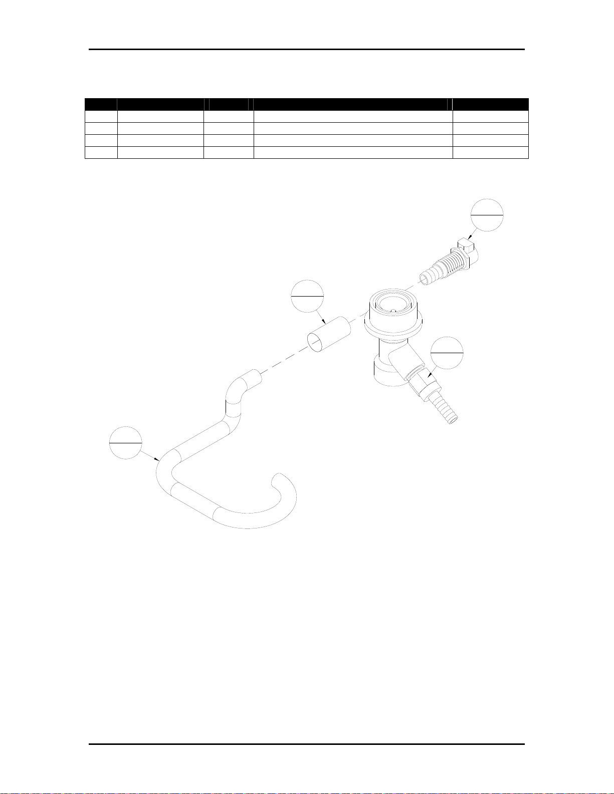
Appendix B Ink Specific Drawings Page B-29
Table B-26: 9104497A – Bottle Coupling Assembly, Aurora
Item Part Number Quantity Description Reference
1 9102132 1 Tubing, Pharmed, 3/8” x ¼”
2 9102236 1 Coupling, Renoir Ink Bottle Cap
3 9102247 1 Shrink Wrap, ½” ID, 13” Lg.
4 9104497 1 Coupling Body, ¼” ID, Panel Mount
Figure B-26: 9104497A – Bottle Coupling Assembly, Aurora
4
1
3
1
2
1
1
1
Buskro Ltd. BK705
Page 99
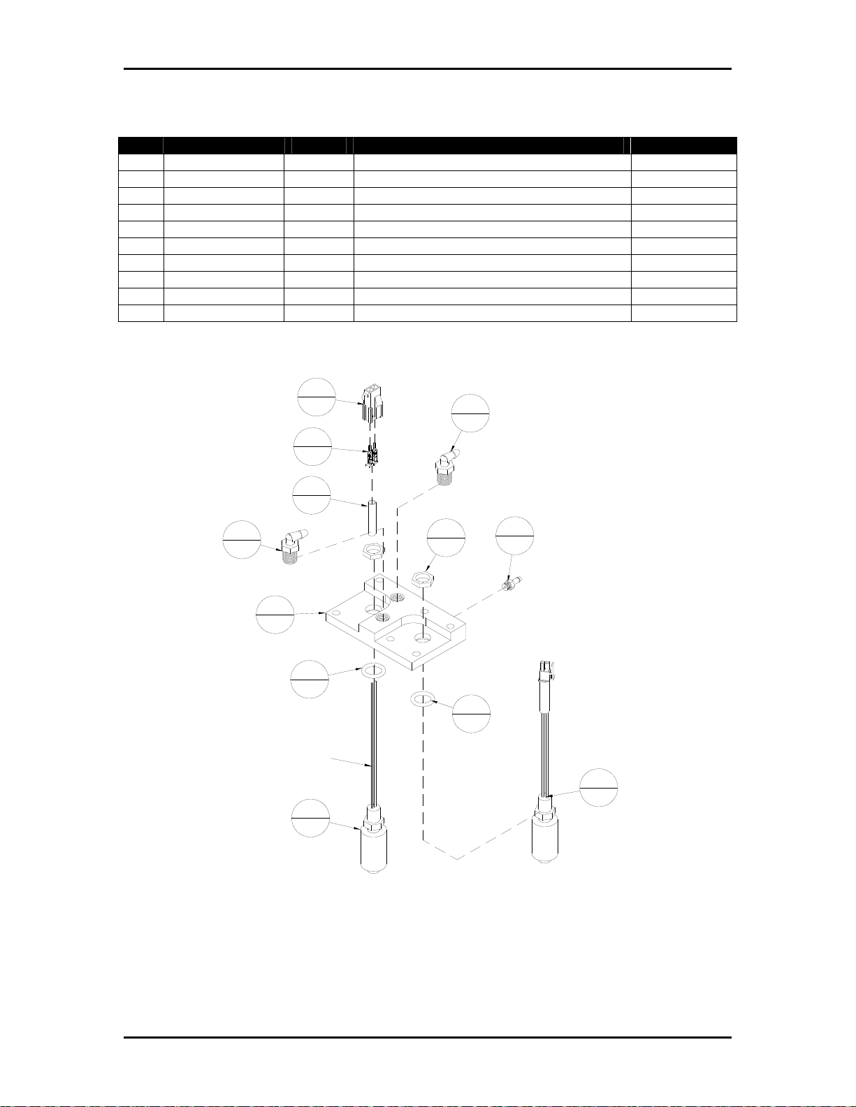
Appendix B Ink Specific Drawings Page B-30
Table B-27: 9104661A – Reservoir Cover Assembly
Item Part Number Quantity Description Reference
1 609000 1 Shrink Wrap, 3/16” ID, 5” Lg
2 9100206 1 Receptacle, 2-Pin, Mini-Fit Jr
3 9100207 2 Contact, Male, 18-22 AWG, Series 5558
4 9100966 1 Float Switch, Micro-miniature
5 9100966A 1 Float Switch Assembly, Secondary
6 9101297 2 O-Ring, 7/16 x 5/8 x 3/32, EPDM P.C.
7 9102085 2 Connector, Elbow, 1/8-27 NPT, 1/8” ID
8 9102973 1 Fitting, 10-32 UNF x 1/8 ID
9 9104661 1 Cover, Reservoir
10 N/A 2 Included with 9100966
Figure B-27: 9104661A – Reservoir Cover Assembly
2
1
3
2
7
2
7
2
9
1
Leave 5" length.
Note: Use teflon tape on two elbow
connectors, 1/8-27 NPT threads.
1
1
10
2
6
2
6
2
4
1
8
1
5
1
Buskro Ltd. BK705
Page 100
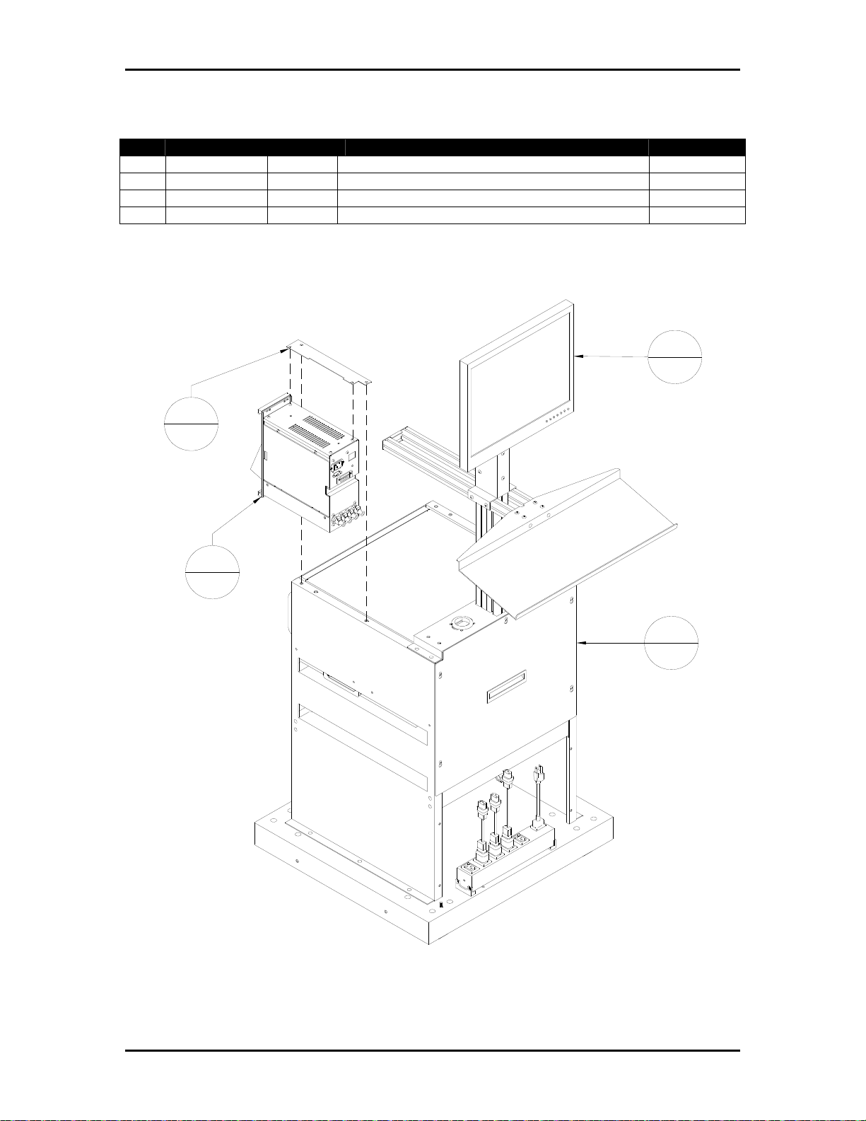
Appendix B Ink Specific Drawings Page B-31
Table B-28: Ezejet with optional Apollo Ink Delivery Module (For Reference)
Item Part Number Quantity Description Reference
1 9104533 1 Bracket (Part of 705-IDM4H-15NA or WD)
2 BK-IDM-4H 1 Ink Delivery, (Part of 705-IDM4H-15NA or WD)
3 BK-705-ST 1 Stand, Apollo Ezejet
4 BK705 1 Controller, Apollo Ezejet (BK-705)
Figure B-28: Ezejet with optional Apollo Ink Delivery Module (For Reference)
4
1
1
1
2
1
3
1
Buskro Ltd. BK705
 Loading...