

Page 1
INSTRUCTION MANUAL
MODEL #: 181561
LIT. #: 98-1532/05-13
Page 2

Page 3
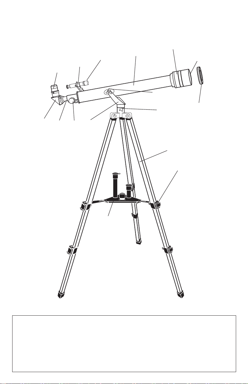
parTs DIagraM
I
H
E
F
G
L
J
M
D
C B
A
K
N
O
P
NOTE: Actual product may have improvements that are not shown in this diagram
A. Yoke Mount
B. Focus Knob
C. Focus Tube
D. Diagonal
E. Eyepiece
F. Finderscope Bracket
G. Finderscope
H. Telescope Main Body
I. Sun Shade
J. Objective Lens
(not shown)
K. Dust Cap (remove before
viewing)
L. Yoke Locking Knob
M. Azimuth Lock
N. Tripod Leg
O. Tripod Leg
Adjusting Knob
P. Accessory Tray
Page 4

assEMbLy DIagraMs
1.
3.
5.
2.
4.
6.
Page 5

TELEsCOpE assEMbLy INsTrUCTIONs
1. Your telescope has adjustable (telescoping) legs (Fig . 1).
2. Stand tripod and expand legs. Loosen the three leg locks. Grab tripod head and lift. Extend the
tripod legs to the desired height (at equal lengths) and tighten the knobs on each leg to hold
it in position (Fig. 1).
3. Attach the accessory tray (P) to the c enter leg braces on the tripod legs (Fig 2) and inser t accessory
tray and bolt through center of tray into braces and tighten bolt.
4. Remove telescope main body from the box. Attach telescope main body (H) by aligning the hole in
the telescope saddle with that in the yoke. Screw yoke locking knobs (L) through both holes and
tighten the knob.
5. Remove the finderscope (G) with finderscope bracket (F) attached from the box. Remove the
two knurled thumbscrews from the telescope main body. Position the finderscope bracket on the
telescope main body so that the holes in the base of the bracket line up with the exposed holes in
the telescope main body. Replace the two-knurled thumbscrews and tighten securely (Fig. 3).
6. Insert diagonal (D) into the focus tube (C). Secure by tightening small retaining screw on the focus
tube (Fig. 4).
7. Insert eyepiece (E) into diagonal (D). Secure by tightening small retaining screw (Fig.5).
NOTE: In all astronomical telescopes, the image appears upside down. With the use of the
diagonal the image appears erect but with a left to right inversion (mirror like). To use the
telescope for terrestrial view and to correct the mirrored image, insert the erecting eyepiece
in between the diagonal and the eyepiece. We recommend the use of the low
magnification eyepiece when the telescope is used for terrestrial viewing. Only
refractor telescopes come with erector eyepieces. Reflectors (mirrors) are used mainly for
astronomical purposes.
The telescope is now fully assembled and ready for use.
8. To use the Barlow, insert Barlow between the diagonal and the eyepiece.
Secure by tightening small retaining screw. Insert eyepiece into open end of Barlow and secure.
CAUTION! Viewing the sun can cause permanent eye damage.
Do not view the sun with this telescope or even with the naked eye.
TO UsE THE FINDErsCOpE
The finderscope is a small low-powered and wide field of view telescope mounted alongside the
main telescope and is used to search for the target and aim the main telescope at it. But before you
can use the finderscope, you will need to line it up with the telescope. This procedure will become
easier with practice.
1. Install the lowest power eyepiece (25mm) into the eyepiece tube. Pick out an easily recognized,
unmoving object no closer than a thousand yards away. Aim your telescope toward your object
until its image is centered in the eyepiece. Lock all the knobs on the mount so the telescope will
not move.
2. Look through the finderscope. If the object you lined up in the telescope is not visible, loosen the
adjustment screws and move the finderscope around until you see it. Once it gets within range,
tighten the adjustment screws while centering the object in the scope. You will note that the
image will shift toward the screw you are tightening (Fig. 6).
3. Adjust screws to center object on the finderscope cross hairs. Recheck your telescope to make
certain it is still on target. If it moved, realign it and adjust your finderscope. If it hasn’t, you’re all
set. Your finderscope is now operational.
Page 6

FINDINg ObjECTs
1. Loosen the altitude locks on the sides of the telescope tube and the silver azimuth lock on the
base of the altazimuth mount, then move the telescope in the desired direction.
2. Look through the finderscope and pan the telescope until the object appears in the field of view.
Once it's in the field of view, tighten the altitude and azimuth locks.
FOCUsINg
1. Once you have found an object in the telescope, turn the focus knob until the image is sharp.
2. To focus on an object that is nearer than your current target, turn the focusing knob toward the
eyepiece (i.e., so that the focus tube moves away from the front of the telescope). For more
distant objects, turn the focus knob in the opposite direction.
3. To achieve a truly sharp focus, never look through glass windows or across objects that produce
heat waves, such as asphalt parking lots.
IMagE OrIENTaTION
1. When observing with a diagonal, the image will be right side up but reversed from left to right.
2. When observing straight through, with the eyepiece inserted directly into the telescope, the
image will be inverted. Also, the image in the finderscope will be inverted.
Ma gN IF ICaTIO N
1. The magnification (or power) of a telescope varies depending upon the focal length of the
eyepiece being used and the focal length of the telescope.
2. To calculate magnification, use the following formula, in which FL = focal length:
Magnification = FL (telescope) in mm
FL (eyepiece)
tECHniCaL sPECiFiCations
Objective Diameter: 50mm
Focal Length: 600mm
Eyepieces: H25mm (Low Power)
H12.5mm (Medium Power)
SR4mm (High Power)
Erecting Eyepiece: 1.5x
Barlow: 2x
Maximum Magnification: 300x *
Accessories: Diagonal, Finderscope,
moon filter
* NOTE: Magnification is calculated magnification (4mm eyepiece+Barlow).
Low power is recommended for most viewing conditions.
EyE LEns CHart & tHEorEtiCaL PowEr Limits
SR 4mm Eye Lens Power:
H 12.5mm Eye Lens Power:
H 25mm Eye Lens Power:
150x
48x
24x
Page 7

WARRANTY / REPAIR
LIFETIME LIMITED WARRANTY
Your Bushnell® telescope is warranted to be free of defects in materials and workmanship
for the lifetime of the original owner. The Lifetime Limited Warranty is an expression of our
confidence in the materials and mechanical workmanship of our products and is your assurance
of a lifetime of dependable service.
If your telescope contains electrical components, these components are warranted to be free of
defects in materials and workmanship for two years after the date of purchase.
In the event of a defect under this warranty, we will, at our option, repair or replace the product,
provided that you return the product postage prepaid. This warranty does not cover damages
caused by misuse, improper handling, installation, or maintenance provided by someone other
than a Bushnell Authorized Service Department.
Any return made under this warranty must be accompanied by the items listed below:
1. A check/money order in the amount of $15.00 to cover the cost of postage and handling
2. Name and address for product return
3. An explanation of the defect
4. Proof of Date Purchased
5. Product should be well packed in a sturdy outside shipping carton, to prevent damage in
transit, with return postage prepaid to the address listed below:
IN U.S.A. Send To: IN CANADA Send To:
Bushnell Outdoor Products Bushnell Outdoor Products
Attn.: Repairs Attn.: Repairs
9200 Cody 25A East Pearce Street, Unit 1
Overland Park, Kansas 66214 Richmond Hill, Ontario L4B 2M9
For products purchased outside the United States or Canada please contact your local dealer for applicable warranty information. In Europe you may also contact Bushnell at: Bushnell Germany GmbH
European Service Centre
Mathias-Brüggen-Str. 80
D-50827 Köln
GERMANY
Tel: +49 221 995568-0
Fax: +49 221 995568-20
This warranty gives you specific legal rights.
You may have other rights which vary from country to country.
©2013 Bushnell Outdoor Products
Page 8

For further questions or additional information please contact:
Bushnell Outdoor Products
9200 Cody, Overland Park, Kansas 66214
(800) 423-3537 • www.bushnell.com
©2013 Bushnell Outdoor Products
 Loading...