

Page 1
LIT. #: 981110/0208
Model 119907
Model 119937
Model 119835
Trail Scout 2008 Models 119835+11 1 3/4/08 12:05:25 AM
Page 2

Trail Scout 2008 Models 119835+12 2 3/4/08 12:05:25 AM
Page 3

3
Congratulations on your purchase of the Bushnell® Digital Trail Scout™ Camera!
is trail camera is designed to record the activity of wildlife game in the outdoors
with its still image and movie modes and weatherproof, rugged construction. is
instruction manual is designed to maximize your understanding of how the camera
operates.
Bushnell Digital Trail Scout Features (All Models)
One of the most revolutionary advances in scouting technology to date, the Bushnell Digital trail
Scout delivers. Boasting one of the most user friendly interfaces in the industry, this trail camera
has a positive toggle switch system that instantly tells you what your camera settings are—without
fumbling with a confusing soware interface! e built-in security system has four levels of security.
Every trail Scout comes complete with padlock, cable lock, ratcheting tree bracket for screw attachment, and soware password that locks out would-be thieves. e high resolution digital camera
delivers crisp views of game in your area and stamps each image with the date, time, your name, and
even the moon phase. Along with regular image mode, there is a movie mode for 15 second video
clips with audio. e camera will function during day and night, sensing game out to 45 feet. e
oversized xenon (standard) ash will reach out to 45 feet. Image delay settings include 30 seconds,
1 minute and 2 minutes. e innovative backlit LCD makes set up a breeze in the eld. e trail
Scout is weatherproof and rugged. Resolution is user selectable from 3 options so you can prioritize
quality vs storage space to best suit your needs. An input for a solar panel accessory (optional) is
provided for use with rechargeable batteries to extend the time your camera can remain unattended
in the eld.
Trail Scout 2008 Models 119835+13 3 3/4/08 12:05:26 AM
Page 4

4
DIGITAL TRAIL SCOUT MODELS
119835—Trail Scout 5.0MP
Great images and scouting technology at a great value. is camera will sense deer and other game as far out
as 45 feet with its passive infrared sensor. Low-battery indicator lights when battery life drops below 25%.
Motion LED lights when activity is detected by the sensor in regular imaging mode and during setup mode
for aiming. Weatherproof. Video Movie mode with audio. Selectable Lo/Med/Hi Resolution (2MP/3MP/
5MP*). Date/time/Moon Phase stamp feature. Comes complete with aircra aluminum security cable,
padlock, and ratcheting tree bracket. Power input jack for optional solar panel. Textured “bark-like” surface
for maximum concealment.
*5MP Hi Res option via soware interpolation, sensor resolution is 3MP
119937/119907 (RealTree AP® Camo)—Trail Scout Pro 7.0MP with Night Vision & Game
Call Module
With all the features of the 5.0 MP Trail Scout plus Night Vision and more, this is the top of the line digital
trail camera. Still photos are captured with your choice of low, medium or high resolution (3MP/5MP/7MP*),
and the video clips include audio collected by a built-in microphone. Choose your setting for regular camera
ash or stealth-like LED ash. LED ash enables you to discretely image game in the night without a visible
ash. ere is no need to worry about your ash giving away your position in popular, busy hunting areas.
And no need to manually set an infrared lter switch for day or night mode to get great results-it’s done for
you automatically. A new feature lets you select from 8 dierent Game Calls to attract any of a wide variety
of animals, with sounding intervals adjustable from 1 to 24 hours. is camera even includes a laser aiming
feature for easy set up in the woods. Comes complete with aircra aluminum security cable, padlock, and
ratcheting tree bracket. Power input jack for optional solar panel. Textured “bark-like” surface for maximum
concealment.
*7MP Hi Res option via soware interpolation, sensor resolution is 5MP
Trail Scout 2008 Models 119835+14 4 3/4/08 12:05:26 AM
Page 5

5
DIGITAL TRAIL SCOUT SPECIFICATIONS
Image Sensor 1/2” CMOS sensor with 3.0 million (119835) or 5.0 million pixels (119907/119937).
“Hi” res setting captures images with 5MP (119835) or 7MP (119937/119907)
resolution via soware processing
Lens F/3.5, eective focal length 42mm. Sight range: 45 degrees
Flash High power electronic Xenon Flash or Infrared 24-lamp LED array. Range: 45 .
PIR Sensor Low noise, high sensitivity passive infrared sensor. Range: 45
Motion LED Indicator Yes
Display Backlit LCD, 2 rows x 8 characters. Auto-o: 3 min. 2-digit event and image
display.
File Format Still image JPG. Movie images AVI 320x 240 pixels per frame. DCF version 1.0 le
management.
Exposure Auto
White Balance Auto
Power Supply 4 x “D” cell batteries. Low battery indicator at 25% remaining power. Solar panel
(optional) input jack (for use with “D” size NiMh type rechargeable batteries only)
Battery Life Approximately 30 days (w/standard alkaline batteries). Or ≥6 mo. using solar panel
with NiMh rechargeable batteries.
(actual battery life will vary with temperature, camera activity and ash usage)
User Password Yes, available range: 0000 to 9999
Other (119937/119907
only)
Laser pointer, IR LED array for night vision infrared imaging
Trail Scout 2008 Models 119835+15 5 3/4/08 12:05:26 AM
Page 6
6
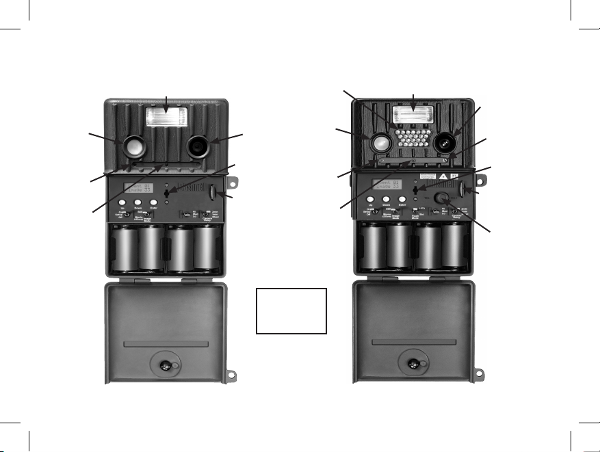
Parts
Guide
Motion
LED
Low
Battery
LED
Flash
Camera
Lens
PIR
SD Card
Slot
Keylock
119835
119937/119907
Standard Flash
PIR
Motion
LED
Infrared
LED Array
Camera
Lens
Laser
Pointer
Low
Battery
LED
Keylock
SD Card
Slot
Game Call
Volume
Trail Scout 2008 Models 119835+16 6 3/4/08 12:05:26 AM
Page 7
7
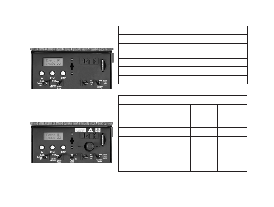
Switch and Setup Description
Switch Position/Setting
Switch #/Function UP CENTER DOWN
K1 (Operating
Mode)
On Setup O
K2 (Image Mode) Still - Movie
K3 (Resolution)* Hi (5MP)
Med (3MP)
Lo (2MP)
K4 (Camera Delay) 2 minutes 1 minute 30 seconds
Switch Position/Setting
Switch #/Function UP CENTER DOWN
K1 (Operating
Mode)
On Setup O
K2 (Image Mode) Still - Movie
K3 (Flash Mode) LED - Standard
(Std)
K4 (Resolution)* Hi (7MP)
Med (5MP)
Lo (3MP)
K5 (Camera Delay) 2 minutes 1 minute 30 seconds
K1 K2 K3 K4
119835 Control Panel
K1 K2 K3 K4 K5
119937/119907 Control Panel
* affects only still photo resolution (video resolution is preset at 320x240 pixels per frame)
Up/Down/Enter
Up/Down/Enter
Trail Scout 2008 Models 119835+17 7 3/4/08 12:05:27 AM
Page 8

8
SETUP GUIDE
NOTE (Model s 119937/119907 Only) : THE LASER POINTER IS ACTIVATED IN THE SET- UP MODE. DO NOT PERMIT
THE LASER POINTER TO BE DIRECTED TOWARD ANYONE’S EYES, TO AVOID POTENTIAL EYE INJURY.
1. K1 - Mode Switch (OFF / SETUP/ ON) :
a) Power ON (UP position): Set K1 to ON position, e LCD display will show “BUSHNELL”
for about 2 seconds.
e LCD will rotate through the DATE\TIME\EVENT&IMAGE displays
when pressing the Up and Down keys.
EVENT nn
IMAGE nn
For mounting directions, please refer to the manual section titled “Using e Trail Scout” .
Before beginning the setup, insert 4 “D” size alkaline batteries as indicated
inside the battery compartment. If you will be using the optional solar
panel accessory, be sure to use rechargeable NiMh batteries only.
b) SETUP Mode [move switch K1 from UP (ON) position to center position]:
Press Up or Down buttons to scroll through choices of DATE, TIME, NAME,PASSWORD, etc to
modify or set these functions. Refer to the next three pages for more details.
c) Power OFF: Set K1 to “O ”, the Trail Scout will be OFF.
Trail Scout 2008 Models 119835+18 8 3/4/08 12:05:27 AM
Page 9

9
Setup Guide (cont.)
Note: See “Other Setup Notes” for details on the moon phase
stamp feature, which is linked to the date you set here.
(2) SET TIME: When the LCD shows Set Time, press the ENTER key to modify the time.
Press Up or Down button to select 1-12, then press ENTER to conrm the two
digit hour. en the cursor will move to the minute.
Press Up or Down button to select 0-59, then press ENTER to conrm the two
digit minute. From SET TIME, press the Down button to set the name.
(3) SET NAME: When the LCD shows “NO NAME”, press ENTER key to modify the
name display. Press Up or Down button to select one character from “A” to “Z”,
“0” to “9”, ”_” , then Press ENTER to conrm, the cursor will move to next character.
ere are 2 lines of 8 characters each for your use. From Set Name, press the Down
button to change the password.
Set Date
09/18/04
Set Time
06: 30 PM
MY NAME
555_1234
When the LCD shows PASSWORD, press the ENTER key to set the password.
Password
Set
(4) SET PASSWORD:
(1) SET DATE: When the LCD shows Set Date, press the ENTER key to modify the date.
Press Up or Down button to select 1-12 then press the ENTER button to
conrm the two digit month. e cursor will then move to the day.
Press Up or Down button to select 1-31 then press ENTER to conrm the two
digit day. en the cursor will move to the year.
Press Up or Down button to select 0-99,then press ENTER to conrm the two
digit year. From Set Date, press the Down button to set the time.
Trail Scout 2008 Models 119835+19 9 3/4/08 12:05:27 AM
Page 10

10
Setup Guide (cont.)
e LCD will show [Password Yes]. To change the password, press Enter.
If you do not want to set a password, you can press the Up or Down key to select NO.
If you selected YES, the LCD shows [New Pswd]. Press the Up or Down key to select the
rst password digit of 0-9. Press ENTER to conrm, the cursor will move to the next digit
to the right. Repeat the process using UP, Down and Enter keys to enter your four digit
password. Press ENTER to conrm.
If you do not want to set a password when the LCD shows (PW YES) , you can press the
U/D button to select No, Aer pressing the ENTER, the LCD display shows (PW NO),
and no password will be set. From Set Password, press the Down button to set Day Time.
When the LCD shows DAY TIME, press ENTER key to set the DAY TIME range. e
LCD will show and underscore under the rst 2 digits in the DAY TIME mode. Press
the up or down keys to set time of 24 hour clock for the specic DAY TIME start hour
desired. Press ENTER to set the DAY TIME start time.
en, underscore will move to the second 2 digits in the DAY TIME mode. Press the up
or down keys to set time of 24 hour clock for the specic DAY TIME end hour desired.
Press ENTER to set the DAY TIME end time.
Now your DAY TIME is dened (NIGHT is dened as the period between DAY end and
start times). If you do not make your own settings for DAY, a default of 6AM~6PM is
used.
Example: 07—18 would dene DAY as from 7AM to 6PM (6PM=18:00 hours on 24 hr clock).
From Set Day Time, press the Down button to set the next user option.
(4) SET PASSWORD (cont.):
(5) SET DAY TIME: (Note: is setting auto switches an infrared lter-see #4 under “Other Setup Notes”)
New Pswd
0 0 0 0
Password
None
Password
Yes
Day Time
07 -- 18
Trail Scout 2008 Models 119835+110 10 3/4/08 12:05:27 AM
Page 11

11
Setup Guide (cont.)
Sound
O
Call
01 Hrs
Photo
Multiple
(6) SELECT SOUND (119907/119937 only): When the LCD shows SOUND, press the
ENTER key to select from the list of 8 dierent game calls (note that the game call module
must be installed for the sound to be audible-see “Attaching the Game Call Module” near
the end of this manual). Press the Up or Down button to nd the desired game call, then
press the ENTER button to conrm the call selection. See “Using the Trail Scout” towards
the back of this manual for a detailed description of each call. Select “OFF” if you wish to
keep the game call module attached but silent. From Select Game Call SOUND, press the
Down button to set the Game Call Interval.
(7) SET GAME CALL INTERVAL (119907/119937 only): When the LCD shows CALL,
press the ENTER key to set the interval at which your selected game call will be sounded,
from 1 to 24 hours between each call. Press the Up or Down button to change the hour
interval setting. From Set CALL, press the Down button to set the Still Photo Mode.
(8) SET STILL PHOTO MODE (all models): When the LCD shows PHOTO, press the
ENTER key to set the Still Photo mode. Press Up or Down button to select Single (only one
photo will be taken per event trigger) or Mutiple (a series of three photos will be taken per
event trigger), then press ENTER to conrm your selection. is is the last user option in
the Setup Menu. From Set STILL PHOTO MODE, press the Down button if you wish to
begin again with the rst item in the Setup Menu, SET DATE. Or, if you are nished with
the Setup process and are ready to start using your Trail Scout, simply change K1 to the ON
(UP) position and the unit will be operating aer a 2 minute delay.
Trail Scout 2008 Models 119835+111 11 3/4/08 12:05:28 AM
Page 12

12
2. K2 – Image Mode Switch (STILL / MOVIE):
Set K2 to either of these settings:
(UP) STILL Photo Mode: Image resolution is determined by the setting of the RES switch, and
photos are stored in JPG format.
(DOWN) MOVIE Mode: e camera can record a 15 second movie, the le format is AVI with
audio.
NOTE: On model# 119835, using MOVIE mode at night will result in dark videos, as the xenon (standard) ash
does not function in MOVIE mode. With models 119937/119907, you may use MOVIE mode at night by setting
switch K3 (Lighting mode) to the LED position (the standard ash does not function in MOVIE mode on these
models either).
(Models 119937/119907 only)
3. K3 - Flash Mode Switch (LED / Standard):
e Game camera has two modes that select which ash type will re under dark conditions:
(a) LED Mode (Infrared LED lamp array):
e IR-LED (infrared) light is invisible to the naked eye, but will provide illumination for the
camera, use it when you do not want to alert the subject at night. is mode can also be used
for nighttime movie capture. During the time dened as “Night”, an infrared blocking lter is
automatically deactivated, so that the IR light generated by the LEDs can create an image. During
the “Day”, the infrared blocking lter is re-activated; therefore, you should use the “Standard” or
xenon ash position for best results when the camera is set to “Day only” time mode.
(b) STD (Standard) Mode: (Xenon ash tube)
You can use Standard mode for twilight/cloudy conditions, or to take color still pictures at night. If
you want to use the MOVIE mode, you can not use Standard ash mode—you must set K3 to LED.
Setup Guide (cont.)
Note: see #4 in “Other Setup Notes” for additional information.
Trail Scout 2008 Models 119835+112 12 3/4/08 12:05:28 AM
Page 13

13
Setup Guide (cont.)
4. K3 (Model 119835) – (Hi/Med/Lo) RESOLUTION:
K4 (Model 119937/119907)– (Hi/Med/Lo) RESOLUTION:
5. K4 (Model 119835)– (30s/1Min/2Min) CAMERA DELAY MODE
K5 (Model 119937/119907) – (30s/1Min/2Min) CAMERA DELAY MODE:
ere are three modes for taking delayed pictures: 30 Sec, 1 Min and 2 Min.
e unit will record EVENTS while CAMERA is in DELAY MODE each time the PIR senses motion.
(a) 30s: Aer the rst picture, a second picture will be taken 30 seconds later.
(b) 1Min: Aer the rst picture, a second picture will be taken 1 minute later.
(c) 2Min: Aer the rst picture, a second picture will be taken 2 minutes later.
e Trail Scout has three still photo resolution options:
(a) Hi: Still photos are taken at the highest (interpolated) resolution setting, 5MP (119835) or 7MP
(119937/119907). Use this setting if you plan to make large prints from your photos, or anytime photo
quality is a higher priority than photo storage space (higher resolution photos generate larger size
les).
(b) Med: Still photos are taken at the actual sensor resolution, 3MP (119835) or 5MP (119937/119907).
is is a good general purpose setting, as it is an ideal compromise between quality and storage space
(c) Lo: Still photos are taken at a lower resolution setting, 2MP (119835) or 3MP (119937/119907).
Use this setting if your priority is being able to store more photos on an SD card, and/or if you will only
be viewing your photos on a computer monitor or making small prints.
Trail Scout 2008 Models 119835+113 13 3/4/08 12:05:28 AM
Page 14

14
GLOSSARY
PIR—Passive Infrared Sensor. Senses motion like typical security motion detector. Requires infrared energy (heat) in addition
to motion to trip sensor to assure detection of live animals.
Event—Any time that the PIR senses motion it counts it as an event. Events are recorded to the SD card in a text le. Events
are recorded continuously during operation.
Image—A digital picture recorded on the SD Card when motion is sensed. Images are taken at the desired delay between images.
Image Delay—Time elapsed between photos while events are sensed and recorded. is is user-set based on wildlife activity
in area.
IR Flash—IR LED Array—Infrared LED Night Vision feature. Emits a burst of infrared light which is invisible to the human
eye. Especially useful for night photos when a visible ash is undesirable. (Featured on Models 119937/119907 only)
Std (Standard) Flash—Xenon ash tube used for low light or night photography. Automatically res if necessary due to dark,
overcast skies or waning light late in the day.
SD Card—Memory card used to store images and events. Trail Scouts are compatible with up to 1GB capacity SD cards,
standard or high speed (all new Trail Scouts include an SD card).
Battery Life—Time that camera will function in the eld. Dependent on temperature, number of images and number of ashes
during that time.
Setup—Using the display menu and buttons to set the date/time, still photo or movies, and password.
Security—One of the most important requirements of any trail camera. e Trail Scouts have 4 security features—padlock tab,
tree bracket, cable lock, and soware password.
Trigger Speed—Time delay between a subject passing in front of PIR sensor and the image capture of that subject.
All Bushnell Trail Cameras have a trigger speed of less than one second.
Trail Scout 2008 Models 119835+114 14 3/4/08 12:05:28 AM
Page 15

15
1. SD CARD SLOT
e unit has a standard SD Card slot. You must push the SD Card in with the SD Card label facing the
Bushnell logo into the SD card slot. Pushing it again will release the SD card, and then you can remove the
SD card from the SD card slot. Insertion or removal of SD card is only recommended when the unit is in
the “OFF” position, as data can be lost or les corrupted if a card is removed while storage is in progress
with the unit powered on.
2. PIR SENSOR
e sensor that triggers the trail camera is Passive InfraRed, or PIR. Infrared energy is essentially heat
energy. e PIR detector operates by sensing a change in the infrared level in its detection zone. is zone
is a cone in the center 10 degrees of the camera’s eld of view. e camera establishes an average long-term
infrared level. When this level increased suddenly the PIR detector signals the camera to record a picture
and/or an event. Because of this eect, the PIR detector will be more sensitive at night, when the average
temperature is lower.
In the Setup mode, you can use PIR sensor to determine the detection zone .When the PIR is sensed, the
PIR Sense Indicator will light. e camera’s eld of view is a 45 degree cone, centered on the PIR detection
zone.
OTHER SETUP NOTES
Trail Scout 2008 Models 119835+115 15 3/4/08 12:05:28 AM
Page 16

16
3. LASER POINTER (Models 119937/119907 Only)
e 119937/119907 Trail Scout camera has a Laser pointer. When you mount the unit on a tree or any
other xed surface and cannot sight from behind the Game Camera, you can use the Laser Pointer to align
the unit.
NOTE: LASER LIGHT IS POTENTIALLY DANGEROUS TO THE EYES.
THE LASER POINTER IS ACTIVATED IN THE SET-UP MODE.
DO NOT PERMIT THE LASER POINTER TO BE DIRECTED
TOWARD ANYONE’S EYES TO AVOID POTENTIAL EYE INJURY.
4. AUTO DAY/NIGHT IR FILTER SWITCH (Models 119937/119907 Only)
e Model 119935/119905 Trail Scout camera has an automatic function which activates a lter in the
camera’s lens system during the time period you dene as “Day” (see “Set Day Time” in the Setup Guide). e
purpose of this lter is to block infrared light, so that photos taken by daylight or with the standard (xenon)
ash tube (in heavy shade or late in the day) will have a normal appearance. is infrared lter is found
in virtually all digital cameras, as their image sensors are sensitive to infrared light as well as visible light
wavelengths. However, during the “Night” time period (from your dened Day end time to Day start time),
the infrared blocking lter is automatically deactivated, or removed from the lens path. is allows the LED
lamp array, which emits invisible infrared light, to be able to create an image on the camera’s CMOS sensor
when the IR light illuminates a subject in front of the lens. Because the infrared lter is activated during the
“Day” time period, using the LED ash mode during the day is not recommended, as the lter will prevent
the infrared light from the LED from reaching the sensor, resulting in dark photos. e standard ash mode
may be selected for night use, however, photos may be slightly pink or reddish in color due to the deactivated
infrared lter. Refer to the following chart:
Other Setup Notes (cont.)
Trail Scout 2008 Models 119835+116 16 3/4/08 12:05:28 AM
Page 17

17
Other Setup Notes (cont.)
Flash
Mode
Day Time Photo Results Night Time Photo Results Recommended
Combination
LED Normal, may be dark during
cloudy conditions or late hours
Black & White, good
exposure
Good (Better night results,
ash is undetected)
STD Normal color & exposure Slight pink or reddish color Good (Better day results)
5. MOON PHASE STAMP
All new Trail Scout models have a “moon phase” stamp feature. is links the current date (as set by the user in
the setup procedure) to the phase of the moon on that date (this data is stored on an internal memory chip), and
imprints a icon on your photo which represents the moon phase when the photo was taken. e moon phase
icon will appear on your photos in the lower le, next to your name and the Bushnell logo. Some hunters will
nd this to be a useful reference, as it can help determine if particular animals are inactive at night when a full or
nearly full moon is present, causing them to be more visible to predators. Or, if some of your night photos seem
to have a darker or lighter background (beyond the range of the LED lamps or ash), you can see if that was
related to how bright the moon was at the time. e icons for the various phases of the moon are shown below:
New Full
Waxing > Waning > New
Note: setting the date and time on your camera is imperative for the unit to function properly,
so that images captured by both day and night will have the best possible appearance (and so
you know when the images are taken). If the date and time are not set up correctly, the automatic
IR (infrared) lter will remain in the “o ” position 24 hrs a day, causing daytime images to
appear somewhat pink.
Trail Scout 2008 Models 119835+117 17 3/4/08 12:05:28 AM
Page 18

18
ABOUT THE INCLUDED MOUNTING BRACKETS
Trail Scout Ratcheting Bracket Installation Tips
A total of 4 brackets are included with all new Trail Scouts (Model#s
119835/119907/119937):
(1) “T” bracket that mounts to the back of the camera
(1) Ratcheting bracket (see photo)
(2) Tree brackets.
The two tree brackets are intended to allow the user to attach brackets to
trees in two different locations, making it easier to move a single camera between the two positions.
The ratcheting bracket (originally sold separately as an optional accessory) is provided as an alternative mounting
method. This bracket can be screwed to a tree, or secured to a tree with the provided cable. When mounting, make
sure that the bracket ratchets down toward the ground. This allows you to mount your camera higher on a tree, to
avoid theft and detection by undesirable animals. After mounting the ratcheting bracket to the tree, attach one of
the tree brackets to the ratcheting bracket with the provided bolts. Then the camera can be locked to the ratcheting
bracket/tree bracket combo in the exact same way that the tree bracket/camera is locked.
Also, the new Trail Scouts have a port on the bottom of the camera for inserting a solar panel power jack (use only
with Bushnell Solar Panel Model# 119750C). When mounting the solar panel, the ratcheting bracket can be used
with it turned upside down (so it ratchets up), to allow the solar panel to be positioned facing UPWARD, to collect
solar energy to power rechargeable NiMh “D” batteries (sold separately) installed in the camera.
Trail Scout 2008 Models 119835+118 18 3/4/08 12:05:29 AM
Page 19

19
1. MOUNTING (Using the “T” bracket and a standard tree bracket):
Mount the trail camera on the tree as shown below.
1. Screw bracket A to the tree.
2. Bolt bracket B on the back of the trail camera.
3. Match bracket B up to bracket A.
4. en, hang bracket B over bracket A.
5. Finally, insert the padlock and lock when setup is completed.
For extra security, you can use the included cable to wrap around the tree
trunk as well.
1. Insert the end with the large lug into bracket A.
2. en, feed the other end of the cable around the tree and back through
the bracket.
3. Tighten the adjustable locking bolt to hold the cable tightly in place (B).
USING THE DIGITAL TRAIL SCOUT
A
B
B
Trail Scout 2008 Models 119835+119 19 3/4/08 12:05:29 AM
Page 20

20
2. POWER ON AND SETUP SWITCH SUMMARY:
Turn the knob 90°counterclockwise and open the front cover.
Set the K1 to ON position,
Input correct Password. Default password is “0000”.
(If the password is entered incorrectly 3 times, the unit will
be powered o automatically. If you want to power ON again
you must set K1 back to OFF and then set K1 to ON)
e LCD will display current IMAGE&EVENT counter.
You can press the Up or Down key to see the DATE, TIME, NAME.
If you want to modify DATE, TIME, NAME or password, set K1 to SETUP.
(See SETUP GUIDE for details)
Aer nishing SETUP, set K1 back to ON position
e unit will delay 2 minutes before functioning to allow you to clear out of your area.
e functions of K2, K3, and K4 can be set in the SETUP or ON Mode.
Aer nishing SETUP, close the front cover and turn the knob to 90°clockwise.
Finally, secure the Trail Scout with a padlock.
Turn the knob 90°
counterclockwise to open
Turn the knob 90°
clockwise to close
Using the Trail Scout (cont.)
Trail Scout 2008 Models 119835+120 20 3/4/08 12:05:29 AM
Page 21

21
Using the Trail Scout (cont.)
Game Call Descriptions (Model 119907/119937 Only)
1. Grunt-Whitetail deer grunt. Will attract whitetail bucks to an area to investigate what other “buck”
is in their territory.
2. Cow Call-Female elk communication call. Will attract elk, especially male bull elk, to the area.
3. Bugle-Male bull elk communication call. Will attract other bull elk to an area to investigate what
other “bull” is in their territory.
4. Antler-Whitetail buck ghting sounds. Will attract other bucks to the area to investigate what other
“bucks” are in their territory.
5. Tending-Whitetail buck grunt sequence. Used by bucks when they are “tending” to a doe. Will
attract bucks.
6. Predator-Small animal in distress sound. Will attract predators such as bobcat, mountain lion,
coyote, wolf to an area.
7. Turkey-Female turkey yelp. This call will attract male tom turkeys.
8. Moose-Male bull moose sound. Will attract other moose to investigate.
Trail Scout 2008 Models 119835+121 21 3/4/08 12:05:29 AM
Page 22

22
Attaching Game Call Module
(remove the plastic plug covering the
connection pins by sliding it up rst)
Game Call Module Attached
Attaching the Game Call Module
(Models 119907 and 119937 only)
Trail Scout 2008 Models 119835+122 22 3/4/08 12:05:30 AM
Page 23

23
Solar Panel Input Jack
Solar Panel
(Optional Accessory)
The (Optional) Solar Panel
(Compatible with models 119835, 119907 & 119937)
WARNING: DO NOT USE the solar panel unless rechargeable (“D” size type NiMh)
batteries have been installed. Using the solar panel with alkaline or other nonrechargeable batteries may result in damage to the unit, not covered by warranty.
Trail Scout 2008 Models 119835+123 23 3/4/08 12:05:30 AM
Page 24

SUPPLEMENTAL OPERATING NOTES
• e LCD showing “ENTER SUSPEND” means the system is going
to suspend activity (sleep mode to conserve battery power).
• Aer setting K1 to ON, the system will begin working aer a
two minute delay. If there is no activity sensed in three minutes,
the system will go to SUSPEND. When the PIR senses activity, the
camera will be activated immediately.
• e LCD showing “RESUME” means the system is active.
• Changing batteries within 20 seconds will avoid the need to reset
the date and time.
Trail Scout 2008 Models 119835+124 24 3/4/08 12:05:30 AM
Page 25

Trail Scout 2008 Models 119835+125 25 3/4/08 12:05:30 AM
Page 26

TWO-YEAR LIMITED WARRANT Y
Your Bushnell® product is warranted to be free of defects in materials and workmanship
for two years aer the date of purchase. In the event of a defect under this warranty, we
will, at our option, repair or replace the product, provided that you return the product
postage prepaid. is warranty does not cover damages caused by misuse, improper handling, installation, or maintenance provided by someone other than a Bushnell Authorized Service Department.
Any return made under this warranty must be accomp anied by the items listed below:
1)
A check/money order in the amount of $10.00 to cover the cost of postage and handling
2) Name and address for product return
3) An explanation of the defect
4) Proof of Date Purchased
5) Pro duct should be well packed in a sturdy outside shipping carton, to prevent damage in transit,
with return postage prepaid to the address listed below:
IN U.S.A. Send To: IN CANADA Send To:
Bushnell Outdoor Products Bushnell Outdoor Products
Attn.: Repairs Attn.: Repairs
8500 Marshall Drive 25A East Pearce Street, Unit 1
Lenexa, Kansas 66214 Richmond Hill, Ontario L4B 2M9
For products purchased outside the United States or Canada please contact your local
dealer for applicable warranty informat ion. In Europe you may also contact Bushnell at:
Bushnell Germany GmbH
European Service Centre
Mathias-Brüggen-Str. 80
D-50827 Köln
GERMANY
Tel: +49 221 995568-0
Fax: +49 221 995568-20
is warranty gives you specic legal rights.
You may have other rights which vary from country to country.
©2008 Bushnell Outdoor Products
FCC Note:
is equipment has been tested and found to comply
with the limits for a Class B digital device, pursuant
to Part 15 of the FCC Rules. ese limits are designed
to provide reasonable protection against harmful
interference in a residential installation. is equipment
generates, uses and can radiate radio frequency energy
and, if not installed and used in accordance with the
instructions, may cause harmful interference to radio
communications. However, there is no guarantee that
interference will not occur in a particular installation.
If this equipment does cause harmful interference to
radio or television reception, which can be determined
by turning the equipment o and on, the user is
encouraged to try to correct the interference by one or
more of the following measures:
· Reorient or relocate the receiving antenna.
·
Increase the separation between the equipment and
receiver
.
· Connect the equipment into an outlet on a circuit
dierent from that to which the receiver is connected.
· Consult the dealer or an experienced radio/TV
technician for help.
Shielded interface cable must b e used with the
equipment in order to comply with the limits for a
digital device pursuant to Subpart B of Part 15 of FCC
Rules.
Specications and designs are subject to change
without any notice or obligation on the part of the
manufacturer.
Trail Scout 2008 Models 119835+126 26 3/4/08 12:05:31 AM
Page 27

Trail Scout 2008 Models 119835+127 27 3/4/08 12:05:31 AM
Page 28

©2008 Bushnell Outdoor Products
For further questions or additional information please contact:
Bushnell Outdoor Products
9200 Cody, Overland Park, Kansas 66214
(800) 423-3537 • www.bushnell.com
Trail Scout 2008 Models 119835+128 28 3/4/08 12:05:31 AM
 Loading...