

Page 1

Instruction manual
Instruction manual
Dear Reader ...
We would like to congratulate you on the purchase of your new motorhome. You have selected a top-quality
vehicle which will afford you many years of enjoyment.
To enable you to always use and operate your motorhome properly and easily, your Bürstner dealer will first
provide you detailed instructions for all important functions when you take delivery.
This manual, the instruction manuals from the base vehicle manufacturer as well as the instruction manuals
from the appliance manufacturer will always be at hand to answer any questions you may have regarding your
motorhome.
Before your first journey
Please familiarise yourself with this manual rather than relying on it strictly for reference.
Fill in the warranty cards for the appliances and special equipment in the individual instructions and send these
cards to the respective manufacturers. This ensures your warranty claim for each appliance.
© 2017 Bürstner GmbH & Co. KG Kehl
T-Modell - 17/18 - Ausgabe 09/17 - 2891 569 - BUE-0029-19EN
Page 2

Instruction manual
T-Modell - 17/18 - Ausgabe 09/17 - 2891569 - BUE-0029-19EN
Page 3

Contents
1Introduction. . . . . . . . . . . . . . . . . . . 7
1.1 General . . . . . . . . . . . . . . . . . . . . . . . . . 8
1.2 Environmental tips. . . . . . . . . . . . . . . . . 8
2Safety. . . . . . . . . . . . . . . . . . . . . . . . 11
2.1 Fire prevention . . . . . . . . . . . . . . . . . . 11
2.1.1 Avoidance of fire risks . . . . . . . . . . . . . 11
2.1.2 Fire-fighting . . . . . . . . . . . . . . . . . . . . . 11
2.1.3 In case of fire. . . . . . . . . . . . . . . . . . . . 11
2.2 General . . . . . . . . . . . . . . . . . . . . . . . . 12
2.3 Road safety . . . . . . . . . . . . . . . . . . . . . 12
2.4 Towing. . . . . . . . . . . . . . . . . . . . . . . . . 14
2.5 Gas system . . . . . . . . . . . . . . . . . . . . . 14
2.5.1 General instructions . . . . . . . . . . . . . . 14
2.5.2 Gas bottles . . . . . . . . . . . . . . . . . . . . . 15
2.6 Electrical system . . . . . . . . . . . . . . . . . 16
2.7 Water system . . . . . . . . . . . . . . . . . . . 16
3 Before the journey . . . . . . . . . . . 17
3.1 Keys . . . . . . . . . . . . . . . . . . . . . . . . . . 17
3.2 Registration . . . . . . . . . . . . . . . . . . . . . 17
3.3 Payload . . . . . . . . . . . . . . . . . . . . . . . . 17
3.3.1 Terms . . . . . . . . . . . . . . . . . . . . . . . . . 18
3.3.2 Calculating the payload . . . . . . . . . . . . 20
3.3.3 Loading the vehicle correctly. . . . . . . . 21
3.3.4 Rear garage/rear storage space . . . . . 22
3.3.5 Bike rack (special equipment) . . . . . . . 23
3.3.6 Load rack SAWIKO
(special equipment) . . . . . . . . . . . . . . . 25
3.4 Towing. . . . . . . . . . . . . . . . . . . . . . . . . 26
3.5 Caravan coupling
(special equipment) . . . . . . . . . . . . . . . 27
3.6 Electrically operated entrance step
(partially special equipment) . . . . . . . . 28
3.7 TV unit (special equipment) . . . . . . . . 29
3.8 Sink and drain basic covers
(partially special equipment) . . . . . . . . 29
3.9 Securing add-on parts . . . . . . . . . . . . . 30
3.10 Gas regulator . . . . . . . . . . . . . . . . . . . 31
3.11 Snow chains (special equipment) . . . . 32
3.12 Road safety . . . . . . . . . . . . . . . . . . . . . 33
4 During the journey . . . . . . . . . . . 35
4.1 Driving the motorhome . . . . . . . . . . . . 35
4.2 Reversing camera
(special equipment) . . . . . . . . . . . . . . . 36
4.3 Driving speed . . . . . . . . . . . . . . . . . . . 36
4.4 Brakes . . . . . . . . . . . . . . . . . . . . . . . . . 37
4.5 Air suspension Goldschmitt
(special equipment) . . . . . . . . . . . . . . . 37
4.6 Seat belts . . . . . . . . . . . . . . . . . . . . . . 38
4.6.1 General . . . . . . . . . . . . . . . . . . . . . . . . 38
4.6.2 Fastening the seat belt correctly . . . . . 38
4.7 Child restraint systems . . . . . . . . . . . . 39
4.8 ISOFIX child safety seat mounting
system (special equipment) . . . . . . . . 41
4.9 Pilot seats for the driver's and
front passenger's seats . . . . . . . . . . . . 42
4.10 Seat heater (special equipment) . . . . . 42
4.11 Headrests . . . . . . . . . . . . . . . . . . . . . . 43
4.12 Seating arrangement . . . . . . . . . . . . . . 43
4.13 Roman shade in the
driver's cabin . . . . . . . . . . . . . . . . . . . . 44
4.13.1 Pleated Roman shades . . . . . . . . . . . . 44
4.13.2 Roman shades, Remis
(partially special equipment) . . . . . . . . 45
4.14 Refuelling . . . . . . . . . . . . . . . . . . . . . . . 45
®
4.15 Topping up AdBlue
(Citroen base vehicle) . . . . . . . . . . . . . 46
5 Pitching the motorhome . . . . . . 47
5.1 Handbrake . . . . . . . . . . . . . . . . . . . . . . 47
5.2 Entrance step. . . . . . . . . . . . . . . . . . . . 47
5.3 Ramps . . . . . . . . . . . . . . . . . . . . . . . . . 47
5.4 Wheel chocks . . . . . . . . . . . . . . . . . . . 47
5.5 Supports . . . . . . . . . . . . . . . . . . . . . . . 48
5.5.1 General instructions . . . . . . . . . . . . . . . 48
5.5.2 Steady legs (special equipment) . . . . . 48
5.5.3 Steady legs (AL-KO)
(special equipment) . . . . . . . . . . . . . . . 49
5.6 230 V connection . . . . . . . . . . . . . . . . . 50
5.7 Refrigerator . . . . . . . . . . . . . . . . . . . . . 50
5.8 Satellite unit (special equipment) . . . . . 50
5.8.1 Satellite unit with manual
satellite selection (TeleSat) . . . . . . . . . 50
5.8.2 Satellite unit with automatic
antenna alignment (Teleco) . . . . . . . . . 52
5.8.3 Satellite unit with automatic
antenna alignment
(Oyster Premium) . . . . . . . . . . . . . . . . 53
5.9 Awning (special equipment). . . . . . . . . 55
6Living . . . . . . . . . . . . . . . . . . . . . . . . 57
6.1 Central locking system
(special equipment) . . . . . . . . . . . . . . . 57
6.2 Conversion door . . . . . . . . . . . . . . . . . 58
6.2.1 Conversion door, outside
(partially special equipment) . . . . . . . . 58
6.2.2 Conversion door, outside . . . . . . . . . . . 59
6.2.3 Conversion door, inside . . . . . . . . . . . . 59
6.2.4 Window of conversion door
(partially special equipment) . . . . . . . . 60
6.2.5 Folding insect screen on
the conversion door
(partially special equipment) . . . . . . . . 60
6.3 External flaps . . . . . . . . . . . . . . . . . . . . 61
6.3.1 Flap lock with recessed handle . . . . . . 61
6.3.2 Garage flap emergency release . . . . . 62
6.3.3 Flap lock with push button . . . . . . . . . . 62
6.3.4 Service unit flap lock . . . . . . . . . . . . . . 63
6.4 Furniture flaps . . . . . . . . . . . . . . . . . . . 63
6.4.1 Furniture flaps with push button. . . . . . 63
3T-Modell - 17/18 - Ausgabe 09/17 - 2891 569 - BUE-0029-19EN
Page 4

Contents
6.4.2 Furniture flaps with handle
and push button . . . . . . . . . . . . . . . . . . 64
6.4.3 Furniture flaps with handle
and unlocking bar. . . . . . . . . . . . . . . . . 64
6.4.4 Furniture flaps with
release handle . . . . . . . . . . . . . . . . . . . 65
6.5 Floor compartment cover . . . . . . . . . . . 65
6.6 Rotating seats . . . . . . . . . . . . . . . . . . . 66
6.7 Light switch . . . . . . . . . . . . . . . . . . . . . 66
6.7.1 Entrance area . . . . . . . . . . . . . . . . . . . 66
6.7.2 Interior . . . . . . . . . . . . . . . . . . . . . . . . . 67
6.7.3 Wardrobe light
(partially special equipment) . . . . . . . . 68
6.7.4 Tube lamp in the rear garage. . . . . . . . 68
6.8 Spotlight . . . . . . . . . . . . . . . . . . . . . . . . 69
6.9 Holder for flat screen . . . . . . . . . . . . . . 70
6.9.1 Holder on the column . . . . . . . . . . . . . . 70
6.9.2 Holder with jointed arm . . . . . . . . . . . . 70
6.9.3 Wall holder . . . . . . . . . . . . . . . . . . . . . . 71
6.9.4 Holder with release lever . . . . . . . . . . . 71
6.9.5 Holder, rotatable . . . . . . . . . . . . . . . . . 72
6.10 Ventilation . . . . . . . . . . . . . . . . . . . . . . 72
6.11 Windows . . . . . . . . . . . . . . . . . . . . . . . 73
6.11.1 Hinged window. . . . . . . . . . . . . . . . . . . 74
6.11.2 Sliding window with pressure lock . . . . 76
6.11.3 Blind and insect screen . . . . . . . . . . . . 76
6.11.4 Roman shade and insect screen . . . . . 77
6.11.5 Roman shades for windscreen,
driver's window and front
passenger's window . . . . . . . . . . . . . . 78
6.12 Skylights. . . . . . . . . . . . . . . . . . . . . . . . 79
6.12.1 Skylight with snap latch . . . . . . . . . . . . 80
6.12.2 Heki skylight (mini and midi)
(partially special equipment) . . . . . . . . 81
6.12.3 Omni-Vent skylight with fan
(special equipment) . . . . . . . . . . . . . . . 82
6.12.4 Skyroof skylight
(partially special equipment) . . . . . . . . 84
6.13 Tables . . . . . . . . . . . . . . . . . . . . . . . . . 86
6.13.1 Fixed table . . . . . . . . . . . . . . . . . . . . . 87
6.13.2 Suspension table . . . . . . . . . . . . . . . . 88
6.13.3 Lift-off table . . . . . . . . . . . . . . . . . . . . . 89
6.13.4 Lift-off table (variant) . . . . . . . . . . . . . . 90
6.13.5 Coffee table
(dependent on model) . . . . . . . . . . . . . 91
6.14 Beds. . . . . . . . . . . . . . . . . . . . . . . . . . . 91
6.14.1 Fixed bed (gas-pressure springs) . . . . 91
6.14.2 Fixed bed
(adjustable head section) . . . . . . . . . . . 92
6.14.3 Fixed bed, hydraulic height
adjustable (special equipment) . . . . . . 92
6.14.4 Fixed bed, height adjustable via
strap system (special equipment) . . . . 93
6.14.5 Pull-down bed,
electrically operated (Ixeo TL) . . . . . . . 94
6.14.6 Pull-down bed,
electrically operated
(Ixeo Time, Lyseo TD) . . . . . . . . . . . . .96
6.14.7 Pull-down bed at the rear,
electrically operated (Lyseo TD)
(special equipment) . . . . . . . . . . . . . . .99
6.15 Converting seating groups
for sleeping . . . . . . . . . . . . . . . . . . . . .101
6.15.1 Conversion of semi-dinette
into guest bed . . . . . . . . . . . . . . . . . . .103
6.15.2 Conversion semi-dinette
into transverse bed
(with additional cushion table) . . . . . .104
6.15.3 Conversion L-seating group
into transverse bed
(with additional cushion table) . . . . . .104
6.15.4 Conversion L-seating group
into transverse bed
(without additional cushion table) . . . .105
6.15.5 Conversion L-seating group
into transverse bed
(Ixeo IT 680, Lyseo TD 590) . . . . . . . .105
6.15.6 Conversion L-seating group into
transverse bed (Ixeo IT 734) . . . . . . .106
6.15.7 Conversion semi-dinette into
transverse bed
(with additional cushion table
and bed widening) . . . . . . . . . . . . . . .106
6.15.8 Conversion L-seating group into
transverse bed (Ixeo IT 640) . . . . . . .107
6.15.9 Lying surface of single beds
(special equipment) . . . . . . . . . . . . . .107
6.16 Shower connection point
for external shower
(special equipment) . . . . . . . . . . . . . .108
7 Gas system . . . . . . . . . . . . . . . . . .109
7.1 General . . . . . . . . . . . . . . . . . . . . . . . .109
7.2 Gas bottles . . . . . . . . . . . . . . . . . . . . .111
7.3 Gas isolator taps. . . . . . . . . . . . . . . . .112
7.4 External gas connection
(special equipment) . . . . . . . . . . . . . .113
7.5 Gas bottle switching facility
(special equipment) . . . . . . . . . . . . . .114
7.6 Changing gas bottles . . . . . . . . . . . . .117
8 Electrical system . . . . . . . . . . . .119
8.1 General safety instructions . . . . . . . . .119
8.2 Terms . . . . . . . . . . . . . . . . . . . . . . . . .119
8.3 USB socket
(partially special equipment). . . . . . . .120
8.4 12 V power supply . . . . . . . . . . . . . . .121
8.4.1 Selector switch for radio
(special equipment) . . . . . . . . . . . . . .121
8.4.2 Starter battery . . . . . . . . . . . . . . . . . . .122
8.4.3 Living area battery . . . . . . . . . . . . . . .123
4 T-Modell - 17/18 - Ausgabe 09/17 - 2891569 - BUE-0029-19EN
Page 5

Contents
8.4.4 Charging batteries via
a 230 V power supply . . . . . . . . . . . . 125
8.4.5 Charging batteries via the
vehicle engine . . . . . . . . . . . . . . . . . . 125
8.5 Transformer/rectifier (EBL 119). . . . . 125
8.5.1 Battery cut-off switch. . . . . . . . . . . . . 127
8.5.2 Battery selector switch . . . . . . . . . . . 127
8.5.3 Battery monitor . . . . . . . . . . . . . . . . . 127
8.5.4 Charging the battery . . . . . . . . . . . . . 128
8.6 Panel LT 96 . . . . . . . . . . . . . . . . . . . 128
8.6.1 Button for 12 V power supply . . . . . . 128
8.6.2 V/tank gauge for battery voltage
and water or waste water levels . . . . 129
8.6.3 Button for water pump. . . . . . . . . . . . 130
8.6.4 Battery alarm for the living
area battery . . . . . . . . . . . . . . . . . . . . 130
8.6.5 12 V indicator lamp . . . . . . . . . . . . . . 130
8.6.6 230 V indicator lamp . . . . . . . . . . . . . 131
8.7 Solar installation
(special equipment) . . . . . . . . . . . . . . 131
8.8 230 V power supply. . . . . . . . . . . . . . 132
8.8.1 230 V connection
(CEE socket outlet) . . . . . . . . . . . . . . 132
8.8.2 Connecting the
230 V power supply. . . . . . . . . . . . . . 132
8.9 Fuses . . . . . . . . . . . . . . . . . . . . . . . . 134
8.9.1 12 V fuses . . . . . . . . . . . . . . . . . . . . . 134
8.9.2 230 V fuse . . . . . . . . . . . . . . . . . . . . . 139
8.10 External socket
(special equipment) . . . . . . . . . . . . . . 140
8.11 Circuit diagrams . . . . . . . . . . . . . . . . 141
8.11.1 Circuit diagrams, interior . . . . . . . . . . 141
8.11.2 Circuit diagram, exterior . . . . . . . . . . 143
9 Appliances . . . . . . . . . . . . . . . . . . 145
9.1 General . . . . . . . . . . . . . . . . . . . . . . . 145
9.2 Heater and boiler. . . . . . . . . . . . . . . . 146
9.2.1 Models with waste gas vent on
the right-hand side of the vehicle . . . 146
9.2.2 To heat properly . . . . . . . . . . . . . . . . 147
9.2.3 Hot-air heater and boiler with
CP plus digital operating unit . . . . . . 147
9.2.4 Alde hot-water heater and boiler
(special equipment) . . . . . . . . . . . . . . 152
9.2.5 Wall flue . . . . . . . . . . . . . . . . . . . . . . 159
9.2.6 Electrical floor warming unit
(special equipment) . . . . . . . . . . . . . . 160
9.3 Air conditioning unit
(special equipment) . . . . . . . . . . . . . . 160
9.3.1 Truma Aventa air
conditioning unit . . . . . . . . . . . . . . . . 160
9.3.2 Telair . . . . . . . . . . . . . . . . . . . . . . . . . 164
9.4 Controlling Truma appliances
with mobile terminal
(special equipment) . . . . . . . . . . . . . . 165
9.5 Cooker . . . . . . . . . . . . . . . . . . . . . . . . 166
9.5.1 Gas cooker . . . . . . . . . . . . . . . . . . . . 167
9.5.2 Gas oven (Dometic)
(special equipment) . . . . . . . . . . . . . . 168
9.5.3 Microwave oven
(special equipment) . . . . . . . . . . . . . . 170
9.5.4 Extractor hood
(special equipment) . . . . . . . . . . . . . . 171
9.6 Refrigerator . . . . . . . . . . . . . . . . . . . . 171
9.6.1 Refrigerator ventilation grill . . . . . . . . 172
9.6.2 Dometic MES/AES. . . . . . . . . . . . . . . 173
9.6.3 Thetford N3000 E/A . . . . . . . . . . . . . . 176
9.6.4 Thetford N97 . . . . . . . . . . . . . . . . . . . 179
9.6.5 Refrigerator door
locking mechanism . . . . . . . . . . . . . . 181
10 Sanitary fittings . . . . . . . . . . . . . 185
10.1 Water supply, general . . . . . . . . . . . . 185
10.2 Water system . . . . . . . . . . . . . . . . . . . 186
10.2.1 Water tank . . . . . . . . . . . . . . . . . . . . . 186
10.2.2 Drinking water filler neck . . . . . . . . . . 186
10.2.3 Filling the water system . . . . . . . . . . . 186
10.2.4 Topping up the water . . . . . . . . . . . . . 188
10.2.5 Closing/opening the overflow. . . . . . . 189
10.2.6 Draining water
(rotary handle with overflow) . . . . . . . 189
10.2.7 Emptying the water system . . . . . . . . 190
10.3 Waste water installation. . . . . . . . . . . 192
10.3.1 Draining waste water . . . . . . . . . . . . . 192
10.3.2 Heater for waste water tank
and waste water pipes
(special equipment) . . . . . . . . . . . . . . 193
10.4 Toilet compartment . . . . . . . . . . . . . . 194
10.5 Toilet . . . . . . . . . . . . . . . . . . . . . . . . . 194
10.5.1 Preparing toilet. . . . . . . . . . . . . . . . . . 195
10.5.2 Swivel toilet . . . . . . . . . . . . . . . . . . . . 196
10.5.3 Toilet with fixed seat . . . . . . . . . . . . . 197
10.5.4 Emptying the sewage tank. . . . . . . . . 198
11 Care . . . . . . . . . . . . . . . . . . . . . . . . . 199
11.1 External care . . . . . . . . . . . . . . . . . . . 199
11.1.1 General . . . . . . . . . . . . . . . . . . . . . . . 199
11.1.2 Washing with a
high-pressure cleaner . . . . . . . . . . . . 199
11.1.3 Washing the vehicle. . . . . . . . . . . . . . 200
11.1.4 Windows of acrylic glass . . . . . . . . . . 200
11.1.5 Entrance step. . . . . . . . . . . . . . . . . . . 200
11.1.6 Air suspension (Goldschmitt) . . . . . . . 201
11.2 Interior care . . . . . . . . . . . . . . . . . . . . 201
11.2.1 Scratch-resistant surface
(kitchen worktop and table top)
(special equipment) . . . . . . . . . . . . . . 202
11.3 Water system . . . . . . . . . . . . . . . . . . . 203
11.3.1 Cleaning the waste water tank. . . . . . 203
11.3.2 Cleaning the water tank . . . . . . . . . . . 203
11.3.3 Cleaning the water pipes . . . . . . . . . . 204
11.3.4 Disinfecting the water system . . . . . . 204
5T-Modell - 17/18 - Ausgabe 09/17 - 2891 569 - BUE-0029-19EN
Page 6

Contents
11.4 Extractor hood . . . . . . . . . . . . . . . . . . 205
11.5 Air conditioning unit . . . . . . . . . . . . . . 205
11.5.1 Truma. . . . . . . . . . . . . . . . . . . . . . . . . 205
11.5.2 Telair . . . . . . . . . . . . . . . . . . . . . . . . . 206
11.6 Winter care. . . . . . . . . . . . . . . . . . . . . 206
11.6.1 Preparations. . . . . . . . . . . . . . . . . . . . 207
11.6.2 Winter operation. . . . . . . . . . . . . . . . . 207
11.6.3 At the end of the winter season . . . . . 207
11.7 Lay-up . . . . . . . . . . . . . . . . . . . . . . . . 207
11.7.1 Temporary lay-up. . . . . . . . . . . . . . . . 207
11.7.2 Winter lay-up . . . . . . . . . . . . . . . . . . . 209
11.7.3 Starting up the vehicle after
a temporary lay-up or after
lay-up over winter. . . . . . . . . . . . . . . . 210
12 Maintenance. . . . . . . . . . . . . . . . . 211
12.1 Inspection work . . . . . . . . . . . . . . . . . 211
12.2 Maintenance work . . . . . . . . . . . . . . . 211
12.3 Doors . . . . . . . . . . . . . . . . . . . . . . . . . 211
12.4 Living area battery . . . . . . . . . . . . . . . 212
12.5 Extractor hood . . . . . . . . . . . . . . . . . . 212
12.6 Alde hot-water heater. . . . . . . . . . . . . 212
12.6.1 Checking the fluid level . . . . . . . . . . . 213
12.6.2 Topping up heating fluid. . . . . . . . . . . 213
12.6.3 Bleeding the heating system . . . . . . . 214
12.7 Replacing bulbs, external. . . . . . . . . . 214
12.7.1 Front lights . . . . . . . . . . . . . . . . . . . . . 215
12.7.2 Rear lights . . . . . . . . . . . . . . . . . . . . . 216
12.7.3 Side lights . . . . . . . . . . . . . . . . . . . . . 216
12.7.4 Types of bulbs for
exterior lighting. . . . . . . . . . . . . . . . . . 217
12.8 Replacing bulbs, internal . . . . . . . . . . 217
12.8.1 Spotlight (movable) . . . . . . . . . . . . . . 218
12.8.2 Surface mounted light . . . . . . . . . . . . 218
12.9 Spare parts . . . . . . . . . . . . . . . . . . . . 219
12.10 Vehicle identification plate . . . . . . . . . 220
12.11 Warning and
information stickers . . . . . . . . . . . . . . 220
13 Wheels and tyres . . . . . . . . . . . . 221
13.1 General . . . . . . . . . . . . . . . . . . . . . . . 221
13.2 Tyre selection. . . . . . . . . . . . . . . . . . . 222
13.3 Tyre specifications . . . . . . . . . . . . . . . 223
13.4 Handling of tyres . . . . . . . . . . . . . . . . 223
13.5 Changing wheels . . . . . . . . . . . . . . . . 224
13.5.1 General instructions . . . . . . . . . . . . . . 224
13.5.2 Tightening torque . . . . . . . . . . . . . . . . 225
13.5.3 Changing a wheel . . . . . . . . . . . . . . . 226
13.6 Spare wheel support
(special equipment) . . . . . . . . . . . . . . 227
13.7 Tyre pressure. . . . . . . . . . . . . . . . . . . 227
14 Troubleshooting . . . . . . . . . . . . .229
14.1 Air suspension (Goldschmitt) . . . . . . .229
14.2 Braking system . . . . . . . . . . . . . . . . . .229
14.3 Satellite unit . . . . . . . . . . . . . . . . . . . .229
14.4 Electrical system. . . . . . . . . . . . . . . . .230
14.5 Gas system. . . . . . . . . . . . . . . . . . . . .232
14.6 Heater/boiler . . . . . . . . . . . . . . . . . . . .233
14.6.1 Truma heater/boiler with
CP plus digital operating unit . . . . . . .233
14.6.2 Alde heater/boiler . . . . . . . . . . . . . . . .235
14.7 Air conditioning unit . . . . . . . . . . . . . .236
14.7.1 Truma . . . . . . . . . . . . . . . . . . . . . . . . .236
14.7.2 Telair. . . . . . . . . . . . . . . . . . . . . . . . . .237
14.8 Cooker . . . . . . . . . . . . . . . . . . . . . . . .237
14.8.1 Gas cooker/gas oven . . . . . . . . . . . . .237
14.8.2 Microwave oven . . . . . . . . . . . . . . . . .238
14.9 Refrigerator. . . . . . . . . . . . . . . . . . . . .238
14.9.1 General faults . . . . . . . . . . . . . . . . . . .238
14.9.2 Dometic MES/AES . . . . . . . . . . . . . . .239
14.9.3 Thetford N 3000 . . . . . . . . . . . . . . . . .240
14.9.4 Thetford N 97 . . . . . . . . . . . . . . . . . . . 240
14.10 Water supply. . . . . . . . . . . . . . . . . . . .241
14.11 Body . . . . . . . . . . . . . . . . . . . . . . . . . .242
14.12 Pull-down bed, electrically
operated (Ixeo TL) . . . . . . . . . . . . . . .243
15 Special equipment . . . . . . . . . . .245
15.1 Weight details for
special equipment. . . . . . . . . . . . . . . .245
16 Technical data . . . . . . . . . . . . . . .249
16.1 View of ground plans . . . . . . . . . . . . .249
16.2 Table of linear measures . . . . . . . . . .256
17 Helpful notes . . . . . . . . . . . . . . . .257
17.1 Traffic rules in foreign countries . . . . .257
17.2 Help on Europe's roads . . . . . . . . . . .257
17.3 Gas supply in European
countries . . . . . . . . . . . . . . . . . . . . . . .258
17.4 Toll regulations in
European countries . . . . . . . . . . . . . .258
17.5 Tips on staying overnight
safely during travel . . . . . . . . . . . . . . .258
17.6 Tips for winter campers . . . . . . . . . . .259
17.7 Travel checklists . . . . . . . . . . . . . . . . .260
18 Inspection plan . . . . . . . . . . . . . .263
6 T-Modell - 17/18 - Ausgabe 09/17 - 2891569 - BUE-0029-19EN
Page 7
Introduction
1
Please read this instruction manual completely before
1Introduction
using the vehicle for the first time!
Always keep this instruction manual in the vehicle. Also inform all other users
of the safety regulations.
X The non-observance of this symbol can lead to personal injury.
Z The non-observance of this symbol can lead to damage being caused to,
or inside the vehicle.
Z This symbol indicates recommendations or special aspects.
Z This symbol indicates actions which lead to environmental awareness.
This instruction manual contains sections which describe model-specific equipment or special equipment. These sections are specially
marked. It may be that your vehicle has not been fitted with this special
equipment. In some cases, the actual equipment of your vehicle may
therefore be different from that shown in some illustrations and descriptions.
However, your vehicle may be fitted with other special equipment not
described in this instruction manual.
Special equipment is described when an explanation is required.
Adhere to the instruction manuals which are separately enclosed.
Z The details "right", "left", "front" and "rear" always refer to the vehicle in
direction of travel.
Z All dimensions and weight details are "approximate".
Should the vehicle be subjected to damage due to a failure to follow the
instructions in this instruction manual, then the guarantee claim is deemed
invalid.
Our vehicles are subjected to continuous development. Please understand
that we reserve the right to alter the form, equipment and technology. Therefore, no claims can be made against the manufacturer as a result of the contents of this instruction manual. The equipment which was known and included
at the time of going to press is described.
The reprinting, translation and copying, including extracts is not permitted
without prior written authorisation from the manufacturer.
7T-Modell - 17/18 - Ausgabe 09/17 - 2891 569 - BUE-0029-19EN
Page 8
1
Introduction
1.1 General
The vehicle is constructed in accordance with the latest technology and the
recognised safety regulations. Nevertheless, personal injury may result and
the vehicle may be damaged if the safety instructions in this instruction manual
are not followed.
Before using the vehicle for the first time, equip it with the legally prescribed
equipment (e.g. First Aid kit, warning vest, hazard warning triangle etc.).
Observe the relevant equipment regulations when travelling abroad.
Only use the vehicle in a technically impeccable condition. Follow the instructions in the instruction manual.
Malfunctions which impair the safety of persons or the vehicle should be
immediately remedied by qualified personnel. To avoid further damages,
observe the duty to avert, minimise or mitigate loss for the user during faults.
Have the vehicle's braking and gas systems inspected and repaired by an
authorised specialist workshop only.
Alterations to the body are only to be carried out with the authorisation of the
manufacturer.
The vehicle is designed for the exclusive transport of persons. Luggage and
accessories may only be transported up to the maximum permissible gross
weight.
Observe the test and inspection periods stipulated by the manufacturer.
1.2 Environmental tips
Z Be considerate of the environment.
Z Remember that: All kinds of waste water and household waste are not to
be disposed of in drains or in the open countryside.
Z On board, collect waste water only in the waste water tank or – if
necessary – in other containers designed for that purpose.
Z Only empty the waste water tank and toilet cassette or sewage tank at dis-
posal stations at the camping or caravan sites, which are especially provided for this purpose. When stopping in towns and communities, observe
the instructions at caravan sites or ask where there are disposal stations.
Z Empty waste water tank as often as possible, even when it is not com-
pletely full (hygiene).
If possible, flush out waste water tank and, if necessary, drainage pipe with
fresh water every time it is emptied.
Z Never allow the toilet cassette or sewage tank to become too full. Empty
the toilet cassette or sewage tank frequently, at the latest as soon as the
level indicator lights up.
Z Separate household waste according to glass, tin cans, plastic and wet
waste also when on a journey. Enquire at the town or community authority
about disposal points. Household waste is not to be disposed of in waste
paper baskets which are situated at car parks.
Z Empty waste bins as often as possible into the containers provided for this
purpose. This helps to avoid unpleasant smells and an accumulation of
rubbish on board.
Z When parked, do not allow the engine to run more than necessary. When
running idle, a cold engine releases more contaminants than usual. The
running temperature of the engine is achieved more quickly whilst the
vehicle is in motion.
8 T-Modell - 17/18 - Ausgabe 09/17 - 2891569 - BUE-0029-19EN
Page 9

Introduction
Z Use an environmentally-friendly WC chemical agent for the WC which can
also be biologically degraded and only use small doses.
Z When staying in towns and communities for long periods, search for
parking areas which are specially reserved for motorhomes. Enquire at the
town or community authority about parking spaces.
Z Always leave the parking places in a clean condition.
1
9T-Modell - 17/18 - Ausgabe 09/17 - 2891 569 - BUE-0029-19EN
Page 10

1
Introduction
10 T-Modell - 17/18 - Ausgabe 09/17 - 2891569 - BUE-0029-19EN
Page 11
Safety
2
Chapter overview
This chapter contains important safety instructions. The safety instructions are
for the protection of persons and property.
2.1 Fire prevention
2.1.1 Avoidance of fire risks
X Never leave children in the vehicle unattended.
X Keep flammable materials clear of heating and cooking appliances.
X Halogen lamps can get very hot. When the light is switched on, there
must always be a safety distance of 30 cm between light and flammable
objects. Fire hazard!
X Never use portable heating or cooking appliances.
X Only authorised qualified personnel may make changes to the electrical
system, gas system or appliances.
2.1.2 Fire-fighting
X Always carry a dry powder fire extinguisher in the vehicle. The fire extin-
guisher must be approved, tested and close at hand.
X Have the fire extinguisher tested at regular intervals by authorised qual-
ified personnel. Observe the date of testing.
X Depending on the equipment, the fire extinguisher is included in the
scope of delivery.
X Always keep a fire blanket near the cooker.
2Safety
2.1.3 In case of fire
X Evacuate all passengers.
X Cut off the electrical power supply and disconnect from the mains.
X Close regulator tap on the gas bottle.
X Sound the alarm and call the fire brigade.
X Fight the fire if this is possible without risk.
Z Acquaint yourself with the position and operation of the emergency exits.
Z Keep escape routes clear.
Z Observe the fire extinguisher instructions for use.
11T-Modell - 17/18 - Ausgabe 09/17 - 2891569 - BUE-0029-19EN
Page 12
2
Safety
2.2 General
X The oxygen in the vehicle interior is used up by breathing and the use of
gas operated appliances. That is why the used air must be replaced permanently. For this purpose, forced ventilation systems (e.g. skylights
with forced ventilation, mushroom-shaped vents or floor vents) are
installed in the vehicle. Never cover or block forced ventilations from the
inside or outside with objects such as e.g. a winter mat. Keep forced ventilations clear of snow and leaves. There is a danger of suffocation due
to increased CO
X Do not use storage spaces or rear garages as places for people or ani-
mals to stay or sleep in. These spaces are not forced-air ventilated.
There is a danger of suffocation due to oxygen deprivation or exhaust
from the heater.
X Observe the headroom of the doors.
Z As far as the fitted appliances (heater, cooker, refrigerator, etc.) and the
base vehicle (engine, brakes, etc.) are concerned, the instruction manuals
are authoritative. It is imperative that they be observed.
Z Fitting accessories or special equipment can alter the dimensions, weight
and road behaviour of the vehicle. Some of the parts must be entered in
the vehicle papers.
Z Only use wheel rims and tyres which are approved for the vehicle. Informa-
tion concerning the size of the approved wheel rims and tyres is included
in the vehicle documents or can be obtained from authorised dealers and
service centres.
Z Firmly apply the handbrake when parking the vehicle.
Z If the maximum permissible gross weight of the vehicle exceeds 4 tonnes,
wheel chocks must be used when parking on gradients. The wheel chocks
are provided as standard for vehicles with a maximum permissible gross
weight exceeding 4 tonnes.
levels.
2
Z When leaving the vehicle, it is imperative that all doors, external flaps and
windows are closed.
Z Always carry the legally prescribed equipment (e.g. first aid kit, warning
vest, hazard warning triangle etc.) with you. The regulations of the host
country apply when travelling abroad.
Z The vehicle may only be driven by drivers who hold a driving licence which
is valid for the respective vehicle class.
Z When selling the vehicle, hand over all instruction manuals for the vehicle
and the fitted appliances.
2.3 Road safety
X Before commencing the journey, carry out a functional check of indi-
cating and lighting equipment, the steering and the brakes.
X If the vehicle has been stationary for a long period (approx. 10 months)
have the braking and gas systems checked by an authorised specialist
workshop.
X Before commencing the journey and after short interruptions of the
journey, ensure that the entrance step is completely retracted.
X Before commencing the journey, secure the pull-down bed.
12 T-Modell - 17/18 - Ausgabe 09/17 - 2891569 - BUE-0029-19EN
Page 13
Safety
X Before commencing the journey, open, lock and secure the shades sit-
2
uated on the windscreen and on the driver's and front passenger's windows.
X Before commencing the journey, rotate all swivel seats in the direction
of travel and lock in position. During the journey, the swivel seats must
remain locked in place in the direction of travel.
X Carefully store all moving parts and all loose objects before starting your
journey.
X Before commencing the journey, place and secure the flat screen and
screen support in the initial position. If the screen holder is installed in a
TV cabinet: Close TV cabinet.
X Before commencing the journey, remove the loose sink cover
(if present) and store it securely in the kitchen unit or wardrobe.
X Before commencing the journey, fix adjustable tables.
X During the journey, persons are only to sit on the permitted seats (see
chapter 4). The authorised number of seats is stipulated in the vehicle
documents.
X Seat belts must be worn by all passengers.
X Fasten your seat belts before the beginning of the journey and keep
them fastened during the journey.
X When travelling, secure children under 13 years of age that are smaller
than 150 cm, with a suitable and officially approved child restraint
system.
X Only attach the child restraint system to seats that are specified for this
purpose. We strongly recommend to install child restraint systems preferably in the second row of seats.
X Never use rearward-facing child restraints on a seat with activated
front airbag. This may lead to death or to serious injuries in children.
X The base vehicle is a commercial vehicle (small truck). Adjust your
driving technique accordingly.
X In case of underpasses, tunnels or similar obstacles, note the total
height of the vehicle (including the roof load).
X In winter, the roof must be free of snow and ice before commencing the
journey.
X Check tyre pressure before a journey or every 2 weeks. Wrong tyre
pressure causes excessive wear and can lead to damage or even to tyre
burst. You can lose control of the vehicle (see section 13.7).
X Do not operate the heater at petrol stations. Danger of explosion!
X Do not operate the heater in closed spaces. Danger of suffocation!
Z Before commencing the journey, distribute the payload evenly within the
vehicle (see chapter 3).
Z When loading the vehicle and when taking a rest from driving, in order to
load luggage or food, for example, observe the maximum permissible
gross weight and axle loads (refer to vehicle documents).
Z Before commencing the journey, close and lock, if possible, all inner doors,
adjustable partition walls, drawers and flaps. Engage the refrigerator door
securing device.
Z Before commencing the journey, close windows and skylights.
13T-Modell - 17/18 - Ausgabe 09/17 - 2891569 - BUE-0029-19EN
Page 14
2
Safety
Z Before commencing the journey, close all external flaps and lock them.
Z Before commencing the journey, remove the external supports and retract
the corner steadies or steady legs, which are fitted to the vehicle.
Z Before commencing the journey, put the antenna in park position.
Z During the initial journey and each time after changing a wheel, re-tighten
the wheel bolts/wheel nuts after 50 km (30 miles). Subsequently inspect
them at regular intervals in order to ensure that they are firmly seated. See
chapter 13 for tightening torque.
Z Tyres should not be older than 6 years as the material becomes brittle over
time (see chapter 13).
Z When using snow chains, the tyres, wheel suspension and steering are
subjected to an additional load. When using snow chains, drive slowly
(maximum speed 50 km/h) and only on streets which are completely
covered with snow. Otherwise the vehicle could be damaged.
2.4 Towing
X Care is to be taken when connecting and detaching a trailer. Risk of acci-
dent and injury!
X No persons are to be between the towing vehicle and the trailer during
positioning for connecting and detaching.
2.5 Gas system
2.5.1 General instructions
X The operator of the gas system is responsible for the performance of
recurring inspections and for complying with the maintenance intervals.
X Before commencing the journey, when leaving the vehicle or when gas
equipment is not in use, close all gas isolator taps and the main isolator
tap on the gas bottle.
X All gas-operated devices (heater, cooker, oven, grill, refrigerator -
depending on the equipment) must be switched off for refuelling, on ferries or in the garage. Danger of explosion!
X Do not use gas-operated devices in closed spaces (e.g. garages).
Danger of poisoning and suffocation!
X Only have the gas system maintained, repaired or altered by an author-
ised specialist workshop.
X Have the gas system checked by an authorised specialist workshop
according to the national regulations before commissioning. This also
applies for not registered vehicles. For modifications to the gas system
have the gas system immediately checked by an authorised specialist
workshop.
X The gas pressure regulator, the gas tubes, and the exhaust gas pipes
must also be inspected. The gas pressure regulator and the gas tubes
must be replaced observing the nationally defined deadlines (the latest
after 10 years). The vehicle owner is responsible for seeing that this is
carried out.
X In case of a defect of the gas system (gas odour, high gas consumption)
there is danger of explosion! Close regulator tap on the gas bottle immediately. Open doors and windows and ventilate well.
14 T-Modell - 17/18 - Ausgabe 09/17 - 2891569 - BUE-0029-19EN
Page 15

Safety
X If the gas system is defective: Do not smoke; do not ignite any open
2
flames, and do not operate electric switches (light switches etc.). Check
the tightness of gas-conducting parts and lines with leakage search
spray. Do not check with an open flame.
X Only the stipulated devices may be connected to internal connections.
Do not operate any device outside the vehicle if it is connected to an
internal connector.
X Before using the cooker make sure that there is sufficient ventilation.
Open a window or the skylight.
X Do not use gas-operated cooking and baking facilities for heating pur-
poses.
X If there are several gas devices, each gas device must have its own gas
isolator tap. If individual gas devices are not in use, close the respective
gas isolator tap.
X Ignition safety valves must close within 1 minute after the gas flame has
extinguished. A clicking sound is audible. Check function from time to
time.
X The built-in gas devices are exclusively meant for use with propane or
butane gas or a mixture of both. The gas pressure regulator as well as
all built-in gas devices are designed for a gas pressure of 30 mbar.
X Propane gas is capable of gasification up to -42 °C, whereas butane gas
gasifies at 0 °C. Below these temperatures no gas pressure is available.
Butane gas is unsuitable for use in winter.
X Due to its function and construction, the gas bottle compartment is a
space which is open to the exterior. Never cover or block up the standard
forced ventilations. Otherwise gas that is emitted can not be diverted to
the outside.
X The gas bottle compartment must not be used as storage space.
X Secure the gas bottle compartment against unauthorised access. To do
this, lock the compartment.
X The regulator tap on the gas bottle must be accessible.
X Only connect gas-operated devices (e.g. gas grill) which have been
designed for a gas pressure of 30 mbar.
X The exhaust gas pipe must be fitted tightly to the heating system and to
the vent and must be sealed. The exhaust gas pipe must not show any
evidence of damage.
X Exhaust fumes must be able to escape into the atmosphere unhindered
and fresh air must be able to enter unhindered. For this reason, keep the
exhaust pipe and intake openings clean and unobstructed (e.g. free from
snow and ice). For this reason, no snow walls or aprons may lie against
the vehicle.
2.5.2 Gas bottles
X Handle full or emptied gas bottles outside the vehicle only with closed
regulator tap and attached protective cap.
X Gas bottles are only to be transported within the designated gas bottle
compartment.
X Place the gas bottles in vertical position in the gas bottle compartment.
X Fasten the gas bottles so that they are unable to turn or tilt.
15T-Modell - 17/18 - Ausgabe 09/17 - 2891569 - BUE-0029-19EN
Page 16
2
Safety
X Connect the gas tube to the gas bottle without tension.
X If the gas bottles are not connected to the gas tube, always place the
protective cap on top.
X Close the regulator tap on the gas bottle before the gas pressure regu-
lator or gas tube are removed from the gas bottle.
X Depending on the connection, unscrew the gas tube from the gas bottle
and screw it on the gas bottle again by hand or using an suitable special
spanner. The screw connection on the gas bottle generally has a lefthand thread. Do not tighten too firmly.
X Only use special gas pressure regulators with a safety valve designed
for vehicle use. Other gas pressure regulators are not permitted and
cannot meet the demanding requirements.
X Use only 11 kg or 5 kg gas bottles. Camping gas bottles with built-in
check valve (blue bottle with max. 2.5 or 3 kg content) are can be used
in exceptional cases with a safety valve.
X Use the shortest possible tube lengths (150 cm max.) for external gas
bottles.
X Never block the floor ventilation openings below the gas bottles.
2.6 Electrical system
X Only allow qualified personnel to work on the electrical system.
X Prior to carrying out work on the electrical system, switch off all devices
and lights, disconnect the battery and disconnect the vehicle from the
mains.
X Only use original fuses with the stipulated values.
X Only replace defective fuses when the cause of the defect is known and
has been remedied.
X Never bridge or repair fuses.
2.7 Water system
X Water left standing in the water tank or in the water pipes becomes
undrinkable after a short period. Therefore, before each use of the
vehicle, thoroughly clean the water pipes and the water tank. After each
use of the vehicle completely empty the water tank and the water pipes.
X In the case of lay-ups lasting more than a week disinfect the water
system before using the vehicle (see chapter 11).
Z If the vehicle is not used for several days or if it is not heated when there is
a risk of frost, empty the entire water system. Make certain that the water
pump is switched off on the panel. Otherwise, the water pump will overheat
and may get damaged. Leave the water taps on in central position. Leave
the safety/drainage valve (if there is one) and all drain cocks open. Frost
damage to appliances, frost damage to the vehicle and deposits in watercarrying components can be avoided in this way.
16 T-Modell - 17/18 - Ausgabe 09/17 - 2891569 - BUE-0029-19EN
Page 17
Before the journey
3
Chapter overview
This chapter contains important information which has to be noted before commencing your journey or carrying out any tasks before the journey.
At the end of the chapter there is a checklist which once again summarises the
most important points.
3.1 Keys
The following keys are included with your vehicle:
Two keys for
z ignition lock
z driver's and passenger's doors
z fuel tank
Two keys for
z conversion door of the body
z drinking water filler neck
z external flaps
Always deposit a replacement key outside the vehicle. Make a note of the key
number. Our authorised dealers and workshops can offer assistance in case
of loss.
3Before the journey
3.2 Registration
Your motorhome is a vehicle which must be registered. Observe national regulations on registration.
Please remember that certain countries require a separate national code
sticker in addition to the EU plate.
3.3 Payload
X Overloading the vehicle and wrong tyre pressure can cause tyres to
burst. You can lose control of the vehicle (see section 13.7).
X The maximum permissible gross weight and the weight including special
equipment fitted at the factory (actual weight) is shown in the vehicle
documents, but not the weight of the loaded vehicle (see section 3.3.1).
For your own safety, we recommend that you have your loaded vehicle
(with all passengers, luggage and personal objects) weighed on a public
weighbridge before you set out on your journey.
X Adapt the speed to the payload. The stopping distance is increased if the
payload is high.
Z Do not exceed the maximum permissible gross weight (permissible total
weight) stated in the vehicle documents and the maximum axle loads as a
result of the payload.
Z Built-in accessories and special equipment reduce the payload.
Z Adhere to the axle load stated in the vehicle documents.
On loading, make sure that the payload's centre of gravity is as low as possible
(directly above the floor of the vehicle). Otherwise this may affect the driving
characteristics of the vehicle.
17T-Modell - 17/18 - Ausgabe 09/17 - 2891569 - BUE-0029-19EN
Page 18
3
Before the journey
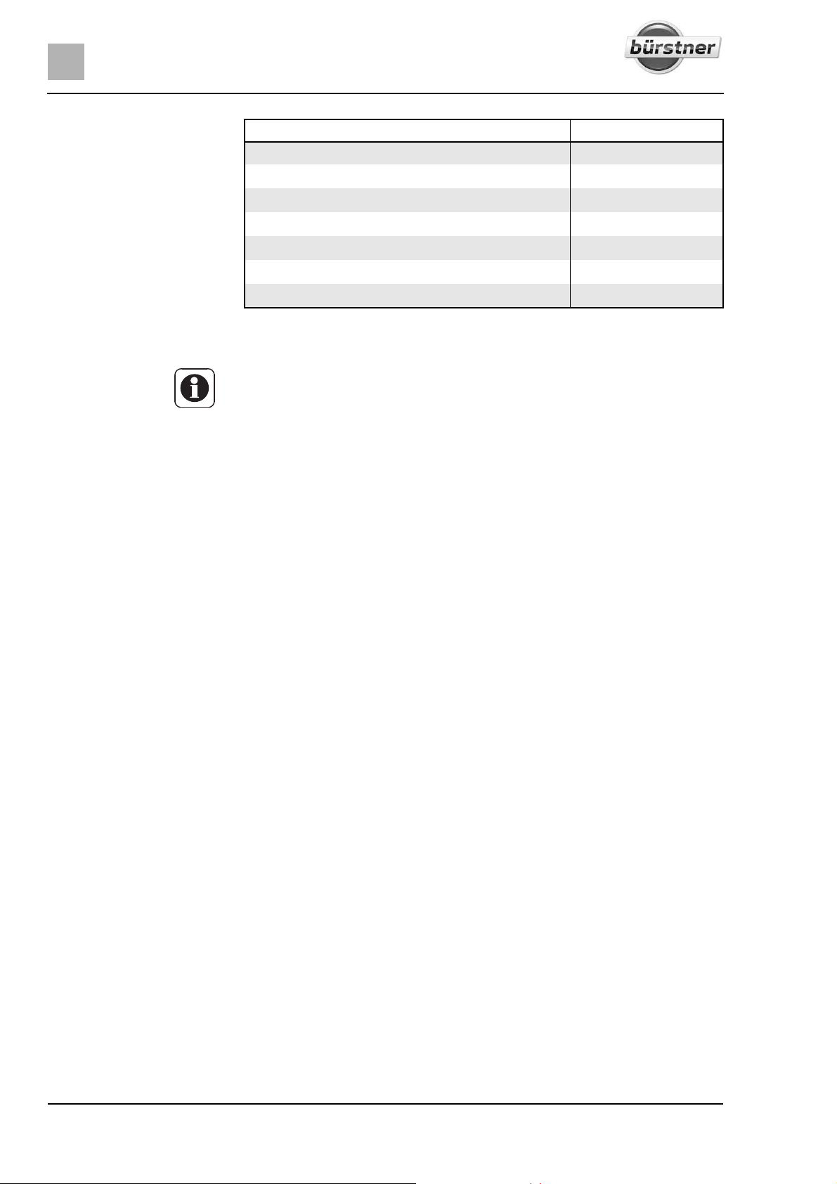
Maximum permitted
payloads
Description Load (kg)
Pull-down bed 200
Roof load 90
Rear garage and rear storage space 200
Pull-out in the rear storage space 60
Bike rack, not lowerable Double/triple 60
Bike rack, lowerable Double/triple 60
Load rack (SAWIKO) 130
3.3.1 Terms
Z Technically speaking, the term "mass" has now replaced the term "weight".
However, "weight" is still the term more frequent in common use. For better
understanding, "mass" is therefore only used in the following sections for
fixed formulations.
Maximum permissible
gross weight in a laden
condition
Actual weight The actual weight consists of the mass in ready-to-drive condition and the
Mass in ready-to-drive
condition
The maximum permissible gross weight in a laden condition is the weight that
a vehicle may never exceed.
The maximum permissible gross weight in a laden condition consists of the
actual weight and the payload.
In the vehicle documents, the manufacturer has specified the maximum permissible gross weight in a laden condition.
weight of the special equipment fitted at the factory.
The mass in ready-to-drive condition is the weight of the ready-to-drive
standard vehicle (excluding special equipment fitted at the factory).
The mass in ready-to-drive condition is made up as follows:
z Unladen weight (mass of the empty vehicle) with factory-installed standard
equipment (excluding special equipment fitted at the factory)
z Driver's weight
z Basic equipment weight
Unladen weight includes lubricants such as oils and coolants which have been
filled, the on-board tool set and a fuel tank which has been filled up to 90 %.
75 kg are calculated for the weight of the driver, regardless of how much the
driver really weighs.
Basic equipment includes all equipment and fluids required for safe and proper
vehicle use. The weight of the basic equipment includes:
z A full fresh water system
z A gas bottle filled up to 90 %
z A full heating system
z The power cables for the 230 V power supply
z A full toilet flushing system
z The installation kit for an auxiliary battery if an auxiliary battery can be used
The waste water and sewage tanks are empty.
18 T-Modell - 17/18 - Ausgabe 09/17 - 2891569 - BUE-0029-19EN
Page 19
Before the journey
3
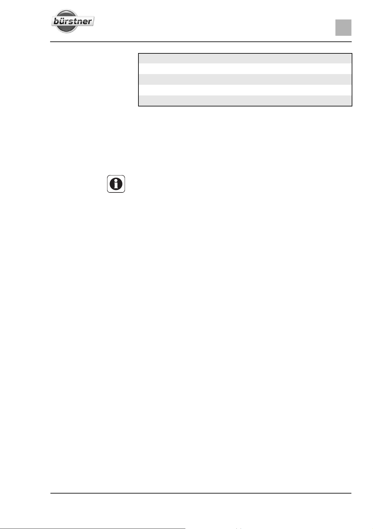
Example for calculating
the basic equipment
Payload The payload is made up as follows:
Conventional load The conventional load is the weight specified by the manufacturer for the pas-
Water tank in the ready-to-drive state with 20 l (overflow open) 20 kg
Aluminium gas bottle + 11.5 kg
Boiler with 20 l + 20 kg
230 V power cable + 4 kg
Total = 55.5 kg
The mass in ready-to-drive condition and the actual weight are shown in the
vehicle documents (e.g. 2900/2950 kg).
z Conventional load
z Additional equipment
z Personal equipment
Z The vehicle's payload can be increased by reducing the actual weight. To
do this, it is allowed for example to empty the fluid containers or to remove
the gas bottles.
You will find explanations on the individual components of the payload in the
following text.
sengers.
Conventional load means: 75 kg are calculated for every seat specified by the
manufacturer, regardless of how much the passengers actually weigh. The
driver's seat is already included as part of the mass in ready-to-drive condition
and must not be calculated as part of the conventional load.
In the vehicle documents, the manufacturer specifies the number of seats.
Additional equipment Additional equipment includes accessories and special equipment. Examples
of additional equipment include:
z Caravan coupling
z Roof rail
z Awning
z Bike or motorcycle rack
z Satellite unit
z Microwave oven
Chapter 15 lists the weights of the various items of special equipment; they
may also be obtained from the manufacturer.
Personal equipment Personal equipment includes all items in the vehicle that are not included in
the conventional load or in the additional equipment. For example, personal
equipment can include the following:
z Foodstuffs
z Crockery
z Television
z Radio
z Clothes
z Bedding
z Toys
z Books
z Toiletries
19T-Modell - 17/18 - Ausgabe 09/17 - 2891569 - BUE-0029-19EN
Page 20
3
Before the journey
No matter where kept, personal equipment also includes:
z Animals
z Bikes
z Boats
z Surfboards
z Sports equipment
For the personal equipment, according to the applicable regulations, the manufacturer must use a minimum weight that is determined according to the following formula:
Formula Minimum weight M (kg) = 10 x N + 10 x L
Explanation N = maximum number of people including the driver, as stated by the manu-
facturer
L = total length of the vehicle in metres
3.3.2 Calculating the payload
X The payload calculation at the factory is partly based on all-inclusive
weights. For safety reasons, the maximum permissible gross weight in
a laden condition must not be exceeded.
X The maximum permissible gross weight and the weight including special
equipment fitted at the factory (actual weight) is shown in the vehicle
documents, but not the weight of the loaded vehicle (see section 3.3.1).
For your own safety, we recommend that you have your loaded vehicle
(with all passengers, luggage and personal objects) weighed on a public
weighbridge before you set out on your journey.
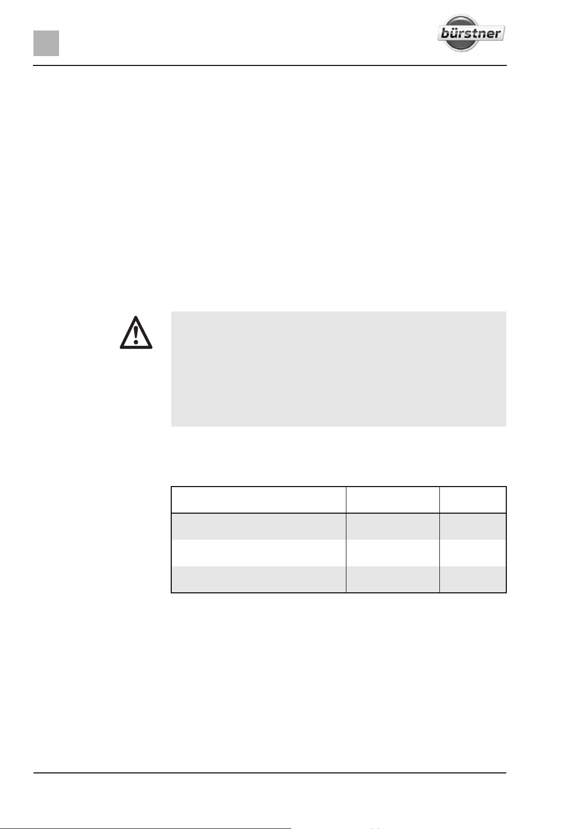
Example for calculating
the payload
The payload (see section 3.3.1) is the difference in weight between
z the maximum permissible gross weight in a laden condition and
z the actual weight.
Maximum permissible gross weight according to vehicle documents
Actual weight including basic equipment
according to vehicle documents
This results in a permissible payload
of
Mass in kg to be
calculated
3500
- 3070
430
Calculation
The calculation of the payload from the difference between the maximum permissible gross weight in laden condition and the actual weight specified by the
manufacturer is however only a theoretical value.
Only if the vehicle is weighed with full tanks (fuel and water), full gas bottles
and complete additional equipment on a public weighbridge, can the actual
payload be determined.
To do this, proceed as follows:
First only drive the vehicle on to the weighbridge with the front wheels and
have it weighed.
Then drive the vehicle on to the weighbridge with the back wheels and have
it weighed.
20 T-Modell - 17/18 - Ausgabe 09/17 - 2891569 - BUE-0029-19EN
Page 21
The individual values give the current axle loads. These are important for the
correct loading of the vehicle (see section 3.3.3). The sum of these values is
the current weight of the vehicle.
The actual payload is the difference between the maximum permissible gross
weight in laden condition and the weighed vehicle weight.
This can be used to determine the weight that remains for the personal equipment:
Determine the weight of the passengers and subtract it from the value for
the actual payload.
The result is the weight that is permitted for the actual load of the personal
equipment.
3.3.3 Loading the vehicle correctly
X For safety reasons, never exceed the maximum permissible gross
weight in a laden condition.
X Distribute the load evenly on the left and right sides of the vehicle.
X Distribute the load evenly on both axles. In doing so, observe the axle
loads specified in the vehicle documents. Observe the permissible loadcarrying capacity of the tyres (see chapter 13).
X Heavy loads behind the rear axle can reduce the load on the front axle
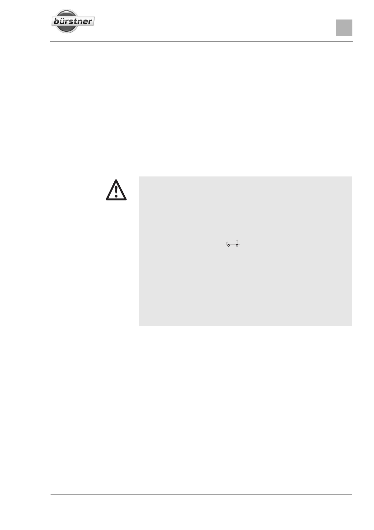
due to the leverage effect ( ). This applies especially to long rear
extensions, if a motorbike is transported on the rear carrier or if there is
a heavy load in the rear storage space. The release of the front axle negatively affects the driving quality, especially for front-driven vehicles.
X Store all objects in such a way that they cannot slip.
X Store heavy objects (awning, tin cans, etc.) close to the axles. Low-lying
storage spaces whose doors do not open in the direction of travel are
particularly suited for storing heavy objects.
X Stack light objects (laundry) in the roof storage cabinets.
X Load the bike rack with bicycles only (max. three units).
Before the journey
3
Large storage spaces, such as the rear garage, also have room for heavy
objects (e.g. motorcycle). This might mean that the axle load on the rear axle
is exceeded.
However, the individual axles may not be overloaded under any circumstances. That is why it is important, at which distance to the axles the load is
stored.
To distribute the load correctly, you will need a scale, a tape measure, a calculator and some time.
Two simple formulas are needed to calculate the effect of the weight of the
load on the axles:
Formulas A x G : R = weight on the rear axle
Weight on the rear axle – G = weight on the front axle
Explanation A = distance between storage space and front axle in cm
G = weight of the load in the storage space in kg
R = wheelbase of the vehicle (distance between axles) in cm
21T-Modell - 17/18 - Ausgabe 09/17 - 2891569 - BUE-0029-19EN
Page 22
3
Before the journey
Z Measure the external distances horizontally from the centre of the front
wheel to the centre of the storage space or to the centre of the back wheel.
Calculating axle loads: Multiply the distance between storage space and front axle (A) with the
weight of the load in the storage space (G) and divide the result by the
wheelbase (R). The result is the weight of the load in the storage space on
the rear axle. Make a note of this weight and of the storage space.
In a second step, subtract the weight in the storage space (G) from the
weight calculated beforehand. If the result is a positive value (example 1),
this means that the load on the front axle is reduced by this value. If the
result is a negative value (example 2), this means that the load on the front
axle is increased. Make a note of this value, too.
Calculate all storage spaces of the vehicle in the same way.
In a last step, add all weights calculated for the rear axle to the rear axle
load and add (or subtract) all weights calculated for the front axle to (from)
the front axle load.
How to determine rear axle load and front axle load is described in
section 3.3.2.
If the calculated value exceeds the permissible axle load, the load must be distributed in a different way.
If the load on the front axle is too low, the grip of the tyres on the road is
reduced (traction), as is the vehicle's steerability. This applies in particular to
vehicles with front-wheel drive. In this case, the load must be redistributed,
too.
Example calculation
3.3.4 Rear garage/rear storage space
Example 1 Example 2
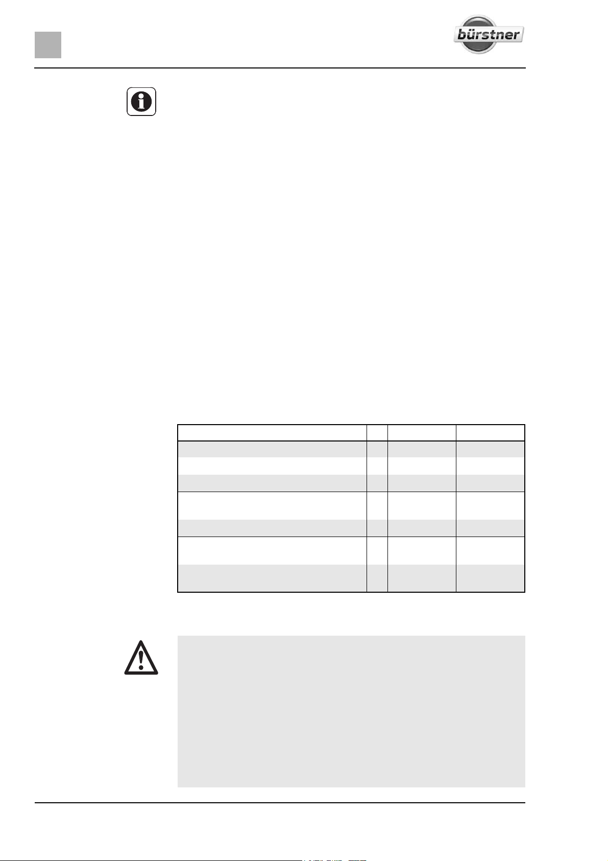
Distance to the front axle A (A1) 450 (cm) (A2) 250 (cm)
Weight in the storage space G x 100 (kg) x 50 (kg)
Wheelbase of the vehicle R ÷ 325 (cm) ÷ 325 (cm)
Load on the rear axle
(add to the axle load)
Weight in the storage space - 100 (kg) - 50 (kg)
Load relief to the front axle
(subtract from the axle load)
Load on the front axle
(add to the axle load)
X Do not use storage spaces or rear garages as places for people or ani-
138.5 (kg) 38.5 (kg)
38.5 (kg)
-11.5 (kg)
mals to stay or sleep in. These spaces are not forced-air ventilated.
There is a danger of suffocation due to oxygen deprivation or exhaust
from the heater.
X Observe the permissible axle loads and maximum permissible gross
weight when loading the rear garage/the rear storage space.
X The maximum permitted load of the rear garage/the rear storage space
is 200 kg. Do not exceed the permissible rear axle load.
X Observe: If the rear garage or (depending on the model) the rear storage
space is loaded to its maximum capacity, this will reduce the load on
the front axle due to the levering action. The driving quality is impaired.
22 T-Modell - 17/18 - Ausgabe 09/17 - 2891569 - BUE-0029-19EN
Page 23
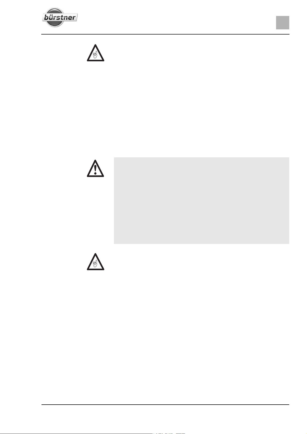
Z Depending on the vehicle equipment, clamping rails with clamping eyelets
are mounted in the rear garage or in the rear storage space. Always secure
loads onto the clamping eyelets. Always use tightening straps or lashing
nets for securing the load, never rubber expanders.
Z When clamping loads, always check that the clamping eyelets are placed
tightly in the clamping rails. If the clamping eyelet is not anchored tightly in
the clamping rail, the load may slide or loosen during forcible movements
of the steering wheel or when braking.
Z Distribute the load evenly. Excessive spot loads can lead to damages of
the floor covering.
Z If there is a pull-out present in the rear storage space: make sure that the
pull-out is engaged.
Z Use the supporting system offered by your dealer if two-wheelers are trans-
ported in the rear garage.
3.3.5 Bike rack (special equipment)
X Observe the permissible axle loads and maximum permissible gross
weight when loading the bike rack.
X A total width of 2.55 m must not be exceeded. Adjust the attachments for
the bikes accordingly. The overhang to the side and rear must be
marked in accordance with the regulations for the country in which you
are travelling.
X Load the bike rack with bicycles only (max. three units).
X Fasten bicycles using the straps provided and check to see that they are
secure after you have driven a few kilometres.
X Check the secure attachment of the bicycles on the bike rack after the
first 10 km and then at each break in the journey.
X Do not use the bike rack as luggage rack or ladder.
Before the journey
3
Z The bike rack is only to be used for transporting bicycles.
Z The gross weight specified by the manufacturer must not be exceeded.
Z The identification plate and rear lights must not be covered.
Z The maximum permissible payload of the bike rack is 60 kg.
Z When loading the bike rack, observe the centre of gravity. If the bike rack
is only loaded with one bicycle, position the bicycle as closely as possible
to the vehicle wall.
Z Driving with a folded out bike rack without bicycles is not permitted.
Z Before every journey, check:
Is the bike rack without bicycles folded in correctly?
Are the bicycles securely fastened to the bike rack using the bike rack
belts?
23T-Modell - 17/18 - Ausgabe 09/17 - 2891569 - BUE-0029-19EN
Page 24
3
Before the journey
Loading the bike rack with
bicycles
Bike rack, not lowerable
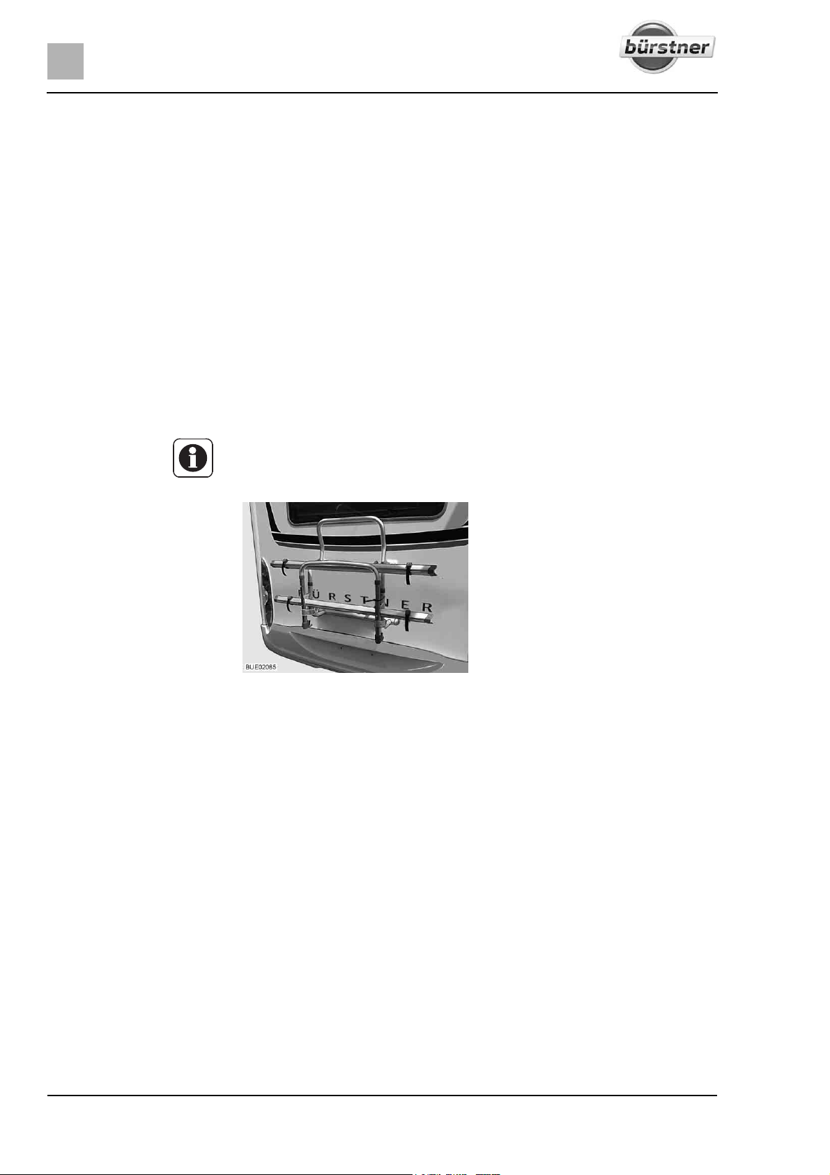
When loading the bike rack, observe the centre of gravity. The centre of gravity
of the bicycles must be as close as possible to the rear wall of the vehicle. The
bike rack should always be loaded from the inside to the outside.
Loading the bike rack correctly:
Depending on the model, fold the bike rack down or pull it out.
Place the heaviest bicycle directly against the rear wall.
Place the lightest bicycles in the centre or on the outside of the bike rack.
Secure the front and rear wheels of each bicycle with the retaining straps
on the bike rack.
In addition, fasten the outermost bicycle depending on the model of the
bike rack on the retaining clip or the retaining bracket and to the spacer
respectively.
If the bike rack is only loaded with one bicycle, position the bicycle as closely
as possible to the rear wall.
Z Also read the manufacturer's instruction manual.
Loading the bicycles:
Fig. 1 Bike rack, not lowerable
Depending on the model, the bike rack can be used to transport 2 or 3 bicycles
comfortably.
Fold the swivel clip down.
Place the bicycles on top and secure them with quick straps.
Fasten the spacer to the frame of the outermost bicycle.
24 T-Modell - 17/18 - Ausgabe 09/17 - 2891569 - BUE-0029-19EN
Page 25
Bike rack, lowerable
Before the journey
Z Also read the manufacturer's instruction manual.
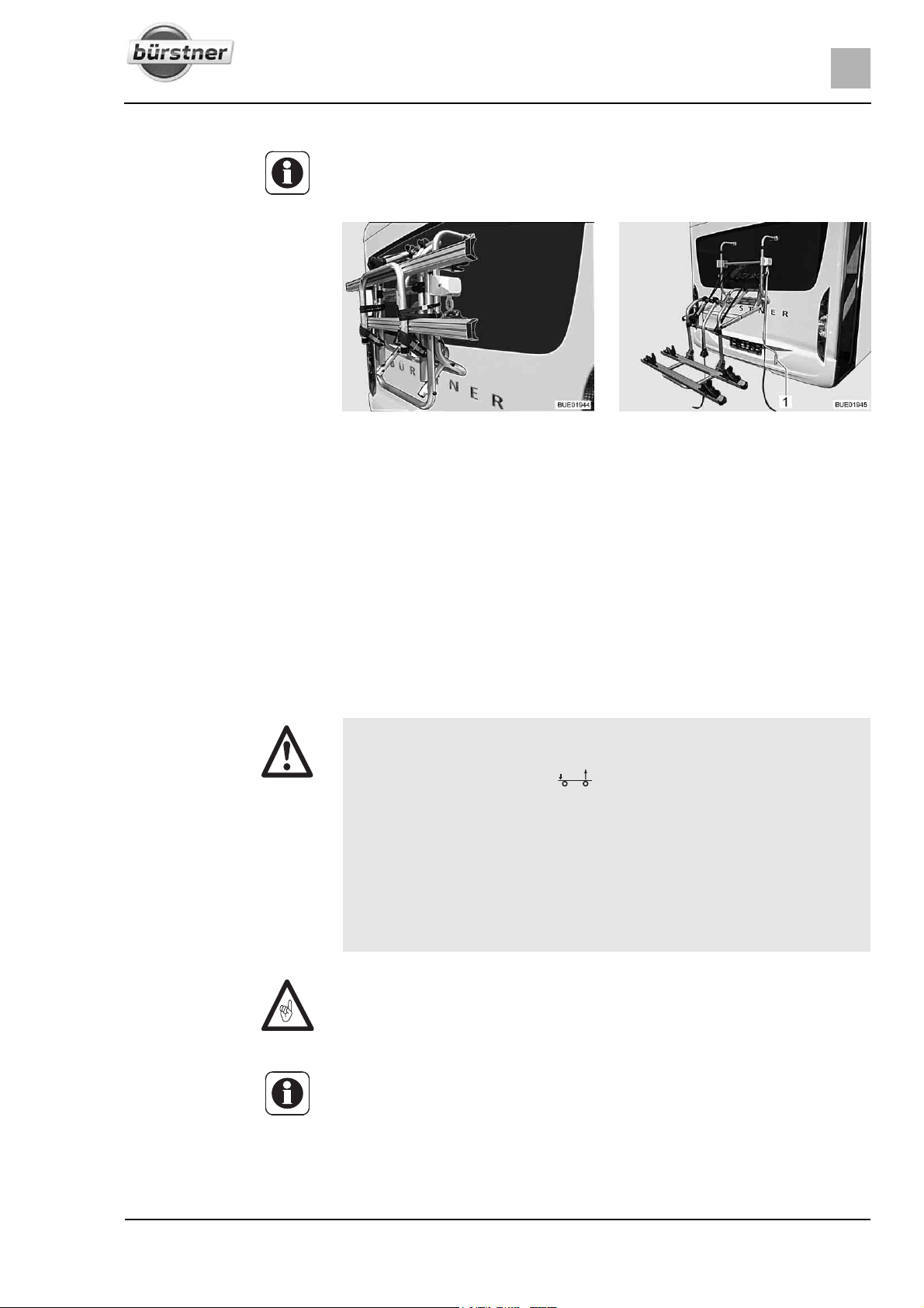
Fig. 2 Bike rack, folded upwards Fig. 3 Bike rack, lowered
3
The bike rack (Fig. 2) permits to easily transport 2 bicycles. Expansion for
3 bicycles is possible. A winding system can be used to lift and lower the bike
rack. The winding system brings the bicycles to gripping height within seconds.
Loading the bicycles:
3.3.6 Load rack SAWIKO (special equipment)
Attach the hand crank (Fig. 3,1) to the bike rack and lower the bike rack to
gripping height.
Place the bicycles on top and secure them with quick straps.
Fasten the bike-block spacer to the frame of the outermost bicycle.
Use the hand crank to raise the bike rack again.
X Do not exceed the rear axle load.
X Heavy loads behind the rear axle can reduce the load on the front axle
due to the leverage effect ( ). This applies especially to long rear
extensions, if a motorbike is transported on the rear carrier or if there is
a heavy load in the rear storage space. The release of the front axle negatively affects the driving quality, especially for front-driven vehicles.
X Always make sure to store the load roadworthy and secure it against
falling.
X The load may not jut out beyond the maximum width of the vehicle. The
lighting and the official licence plate on the load rack may not be covered
by the load.
Z The load rack and caravan coupling must not be used simultaneously.
Z An entry must be made in the vehicle documents in order to attach a load
rack. The required documents are enclosed with the load rack.
Z Have your dealer or service centre install the load rack.
Z Observe the country-specific regulations.
Z Also read the manufacturer's instruction manual.
25T-Modell - 17/18 - Ausgabe 09/17 - 2891569 - BUE-0029-19EN
Page 26
3
Before the journey
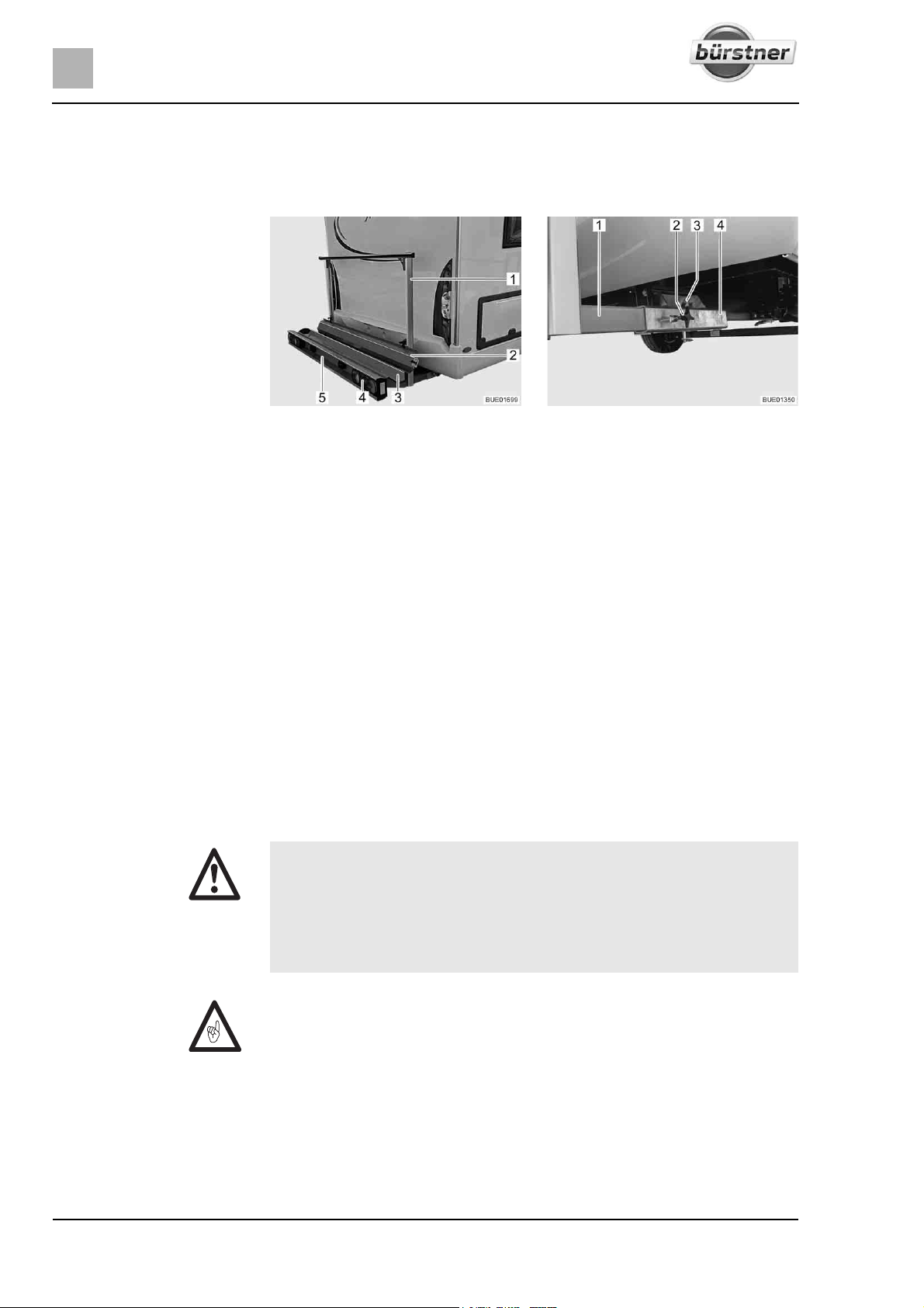
The load rack permits transport of a load weighing up to 130 kg. For the transport of the load different attachments are available. They are e.g. bike rack or
a transport box. Our authorised dealers and service centres will be happy to
advise you.
Fig. 4 Load rack Fig. 5 Attachment to vehicle
The load rack (Fig. 4) permits transport of a motorcycle or a motor scooter
weighing up to 130 kg.
Scope of delivery The following parts belong to the scope of delivery:
z Rack trough (Fig. 4,3) and retaining clip (Fig. 4,1) with attachment to
vehicle (Fig. 5)
z Rear lights (Fig. 4,4)
z Vehicle licence plate light (Fig. 4,5)
z 13-pole Jäger System plug
z Ramp (Fig. 4,2)
Attachment to vehicle The two side members (Fig. 5,1) of the load rack are fixed to the floor of the
vehicle by means of tommy screws (Fig. 5,2) on the square drives (Fig. 5,4).
The load rack is secured by a bolt (Fig. 5,3) with locking ring.
Entry in the vehicle
documents
Have your dealer or service centre install the add-on parts. They will also take
care of all the formalities for you.
3.4 Towing
X Care is to be taken when connecting and detaching a trailer. Risk of acci-
dent and injury!
X No persons are to be between the towing vehicle and the trailer during
positioning for connecting and detaching.
X Observe the permissible nose weight and rear axle load of the
motorhome. Refer to the vehicle documents for the rear axle load.
Z Trailer with an overrun brake: Do not connect or detach trailer with the
overrun brake on.
Z Caravan coupling with detachable ball neck: If the ball neck is mounted
incorrectly, there is the danger of the trailer breaking away. Observe the
instruction manual for the caravan coupling.
Z The tow ball only fits onto the supplied mount. If the tow ball must be
replaced, the mount must also be replaced.
Z If the vehicle is equipped with air suspension: the distance between the tow
ball of the caravan coupling and the road must be 350 to 420 mm in loaded
condition.
26 T-Modell - 17/18 - Ausgabe 09/17 - 2891569 - BUE-0029-19EN
Page 27
Before the journey
Depending on the model, different nose weights may apply for the caravan
couplings. Refer to the following table for the respective permissible nose
weight.
Model Permissible nose weight
SAWIKO MT019 75 kg
SAWIKO (other) 100 kg
Linnepe 100 kg
AL-KO 80 kg
3.5 Caravan coupling (special equipment)
X When mounting a caravan coupling, see the vehicle documents for infor-
mation on maximum nose weight and caravan load.
X Retighten the caravan coupling fixing screws after 1000 operating
hours.
Z The load rack and caravan coupling must not be used simultaneously.
3
Entry in the vehicle
documents
Z If the caravan coupling is retrofitted, this must be entered in the vehicle doc-
uments. The required documents are enclosed with the caravan coupling.
Z If the caravan coupling was fitted at the factory, this is entered in the vehicle
documents. Always keep the appropriate documents in the vehicle.
Z Also read the manufacturer's instruction manual.
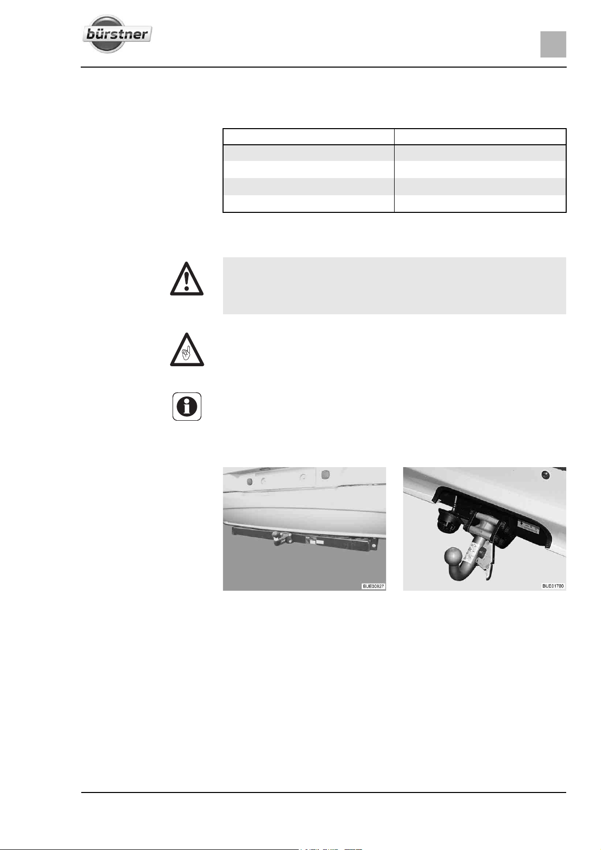
Fig. 6 Caravan coupling, rigid Fig. 7 Caravan coupling, detachable
Have your dealer or service centre install the add-on parts. They will also take
care of all the formalities for you.
27T-Modell - 17/18 - Ausgabe 09/17 - 2891569 - BUE-0029-19EN
Page 28
3
Before the journey
3.6 Electrically operated entrance step (partially special equipment)
X Before commencing the journey and after short interruptions of the
journey, ensure that the entrance step is completely retracted.
X Do not stand in the direct range of the entrance step while it is being
retracted or extended.
X Do not step on the entrance step until it has extended completely. There
is a risk of injury.
X Do not under any circumstances raise or lower persons or loads with the
entrance step.
Z Take note of the different step heights and make certain that the ground is
firm and even when exiting.
Z Do not grease or lubricate the pivot bearing and joints of the entrance step
(see chapter 11).
Z The button to operate the entrance step is located on the inside of the
vehicle in the area of the conversion door.
Z If the entrance step has not been retracted correctly, a red indicator lamp
lights up on the dashboard when switching on the ignition.
Z Follow the warning notice on the entrance step.
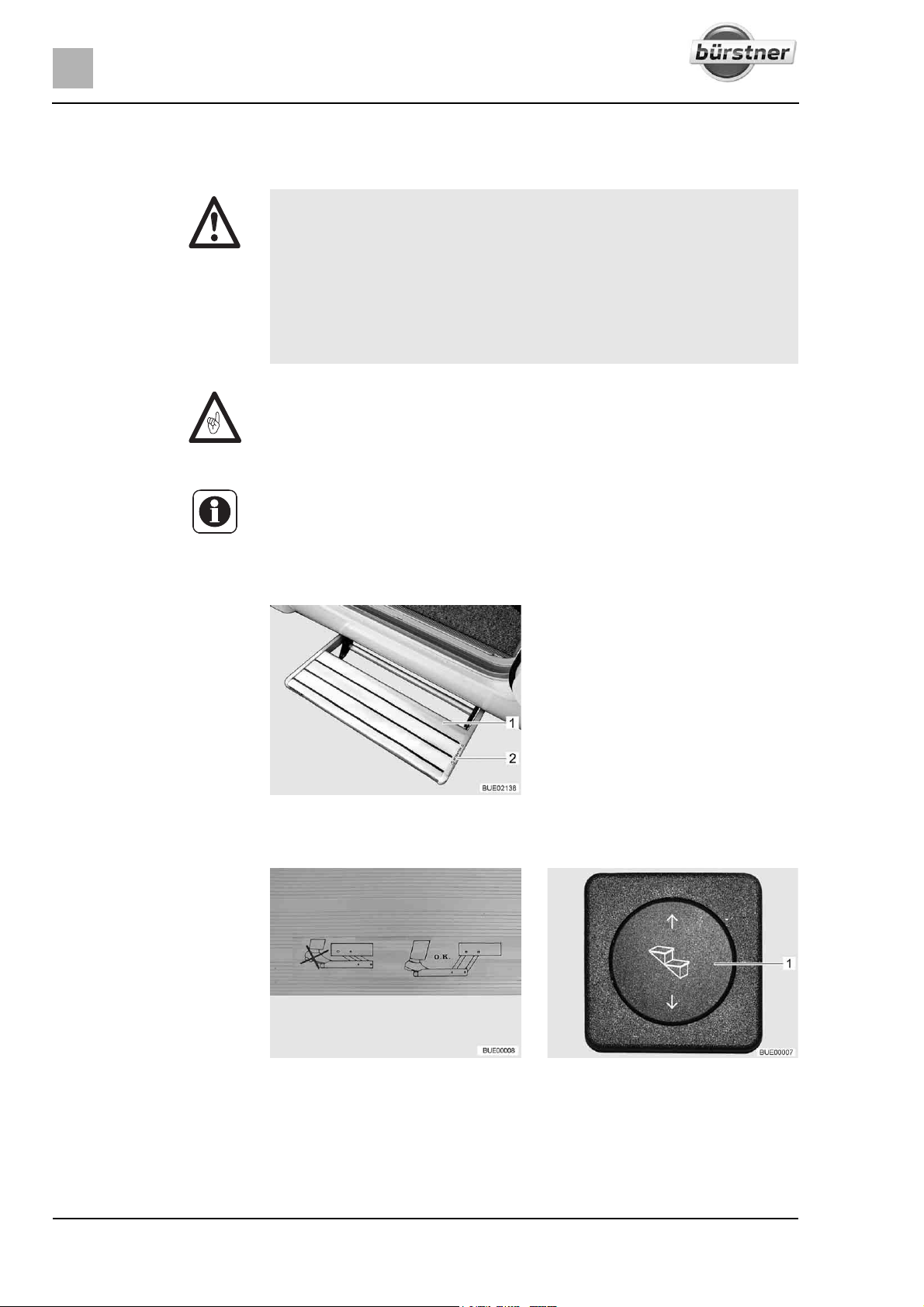
1 Entrance step
2 "Risk of crushing" warning notice
Fig. 8 Entrance step
The vehicles have a one-step, electrically extendable entrance step (Fig. 8,1).
Fig. 9 Warning notice for entrance
Before stepping on the entrance step, fully extend it (Fig. 9).
Extending:
28 T-Modell - 17/18 - Ausgabe 09/17 - 2891569 - BUE-0029-19EN
Press the rocker button (Fig. 10,1) down and hold it pressed (at least
step
3 seconds) until the entrance step has extended completely.
Fig. 10 Operating button for entrance
step
Page 29
Before the journey
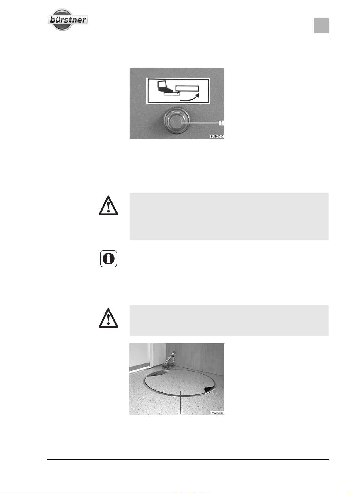
Retracting: Press the rocker button (Fig. 10,1) up until the entrance step has retracted
completely.
Fig. 11 Indicator lamp
When the ignition is switched on and the entrance step is extended, an indicator lamp (Fig. 11,1) is illuminated on the dashboard.
3
3.7 TV unit (special equipment)
X Before commencing the journey, place and secure the flat screen and
screen support in the initial position. If the screen holder is installed in a
TV cabinet: Close TV cabinet.
X Before commencing the journey, ensure that the antenna is in park posi-
tion. Danger of accidents! Park position means: The antenna points
towards the back, is fully lowered and is locked in this position.
Z Further information on positioning the flat screen can be obtained from
chapter 6.
3.8 Sink and drain basic covers (partially special equipment)
X In the event of an accident or emergency braking, the loose sink
(Fig. 12,1) and drain basin covers could injure the occupants of the
vehicle. Before commencing the journey, take the loose covers off and
store them securely in the kitchen unit or wardrobe.
Fig. 12 Sink cover (example)
29T-Modell - 17/18 - Ausgabe 09/17 - 2891569 - BUE-0029-19EN
Page 30
3
Before the journey
3.9 Securing add-on parts
X In the event of an accident or emergency braking, loose add-on parts
could injure the occupants of the vehicle. Before setting off, secure loose
add-on parts in the holders provided or stow them in a secure place
inside the vehicle.
Z Unsecured flaps and doors can spring open during the journey and
damage parts of the interior. Secure all flaps and doors before setting off.
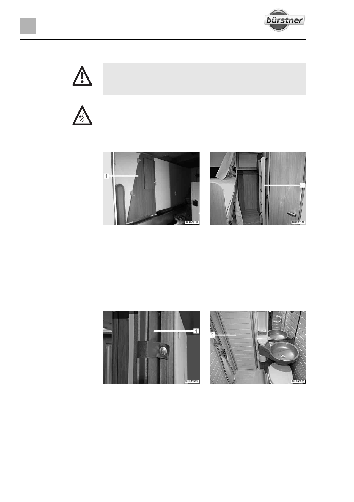
Add-on parts Add-on parts include bed widenings, ladders or table extensions.
Fig. 13 Bed widening in the rear
Securing add-on parts:
Doors and flaps Doors are, for example, inner doors or partition walls. See section 6.4 for fur-
Place the add-on parts (Fig. 13,1 and Fig. 14,1) in the holders provided and
If no holder is provided for the add-on part, stow the add-on part in a
niture flaps.
Fig. 15 Sliding door Fig. 16 Shower partition
garage
secure them with the available means of attachment.
storage space the doors of which cannot be opened in the direction of
travel (e.g. wardrobe or rear storage space).
Fig. 14 Access ladder in the wardrobe
Securing doors:
30 T-Modell - 17/18 - Ausgabe 09/17 - 2891569 - BUE-0029-19EN
Secure doors (Fig. 15,1) or partition walls (Fig. 16,1) with the locks or
means of securing provided.
Page 31
Before the journey
3
Coffee table of the rear
seating group
Securing the coffee table:
3.10 Gas regulator
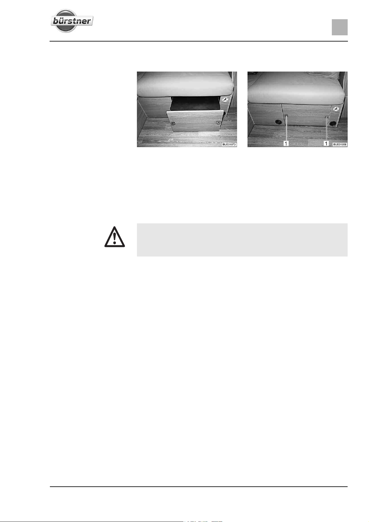
A movable coffee table is installed in the seat box of the rear seating group.
Fig. 17 Bench and coffee table Fig. 18 Coffee table lock
Lower the coffee table.
Run the coffee table into the seat box.
Press the push buttons (Fig. 18,1) on the seat box panel. The coffee table
is secured.
X Operating gas-operated appliances during the journey is permitted only
if the gas system has the relevant equipment. The hose break guard and
crash protection unit (CPU) prevent the gas form escaping in the event
of an accident.
Depending on the equipment, different gas regulators can be installed in the
vehicle.
If a gas regulator other than the one listed below is installed in the vehicle, the
regulator tap on the gas bottle and the gas isolator taps must be closed during
the journey.
31T-Modell - 17/18 - Ausgabe 09/17 - 2891569 - BUE-0029-19EN
Page 32
3
Before the journey
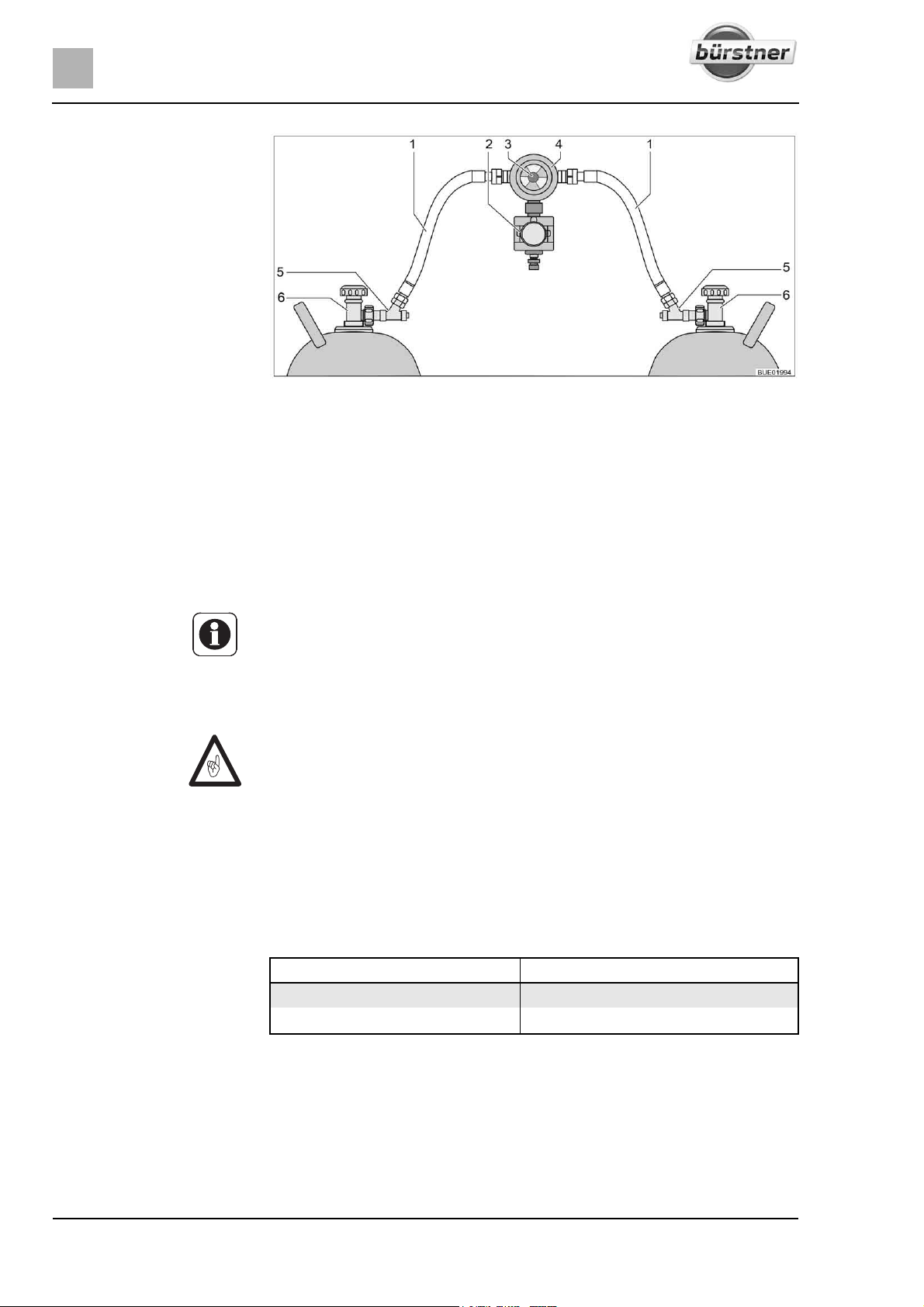
Fig. 19 Gas regulator with CPU and hose break guard
1 Gas tube
2 Crash protection unit (CPU)
3 Knob for manual switching of the gas bottles
4 Gas pressure regulator with reversing valve and indicator
5 Hose break guard
6 Regulator tap on the gas bottle
Gas regulator with CPU
and hose break guard
3.11 Snow chains (special equipment)
If a gas regulator with crash protection unit (Fig. 19,2) and hose break guard
(Fig. 19,5) is installed in the vehicle:
The regulator tap on the gas bottle and the gas isolator taps may remain open
during the journey. Gas-operated appliances may be on during the journey.
Z If in doubt, get the relevant information from authorised dealers or service
centres.
Z Only mount snow chains if there is a clearance of at least 50 mm between
the tyres and the vehicle body.
Z When using snow chains, the tyres, wheel suspension and steering are
subjected to an additional load. When using snow chains, drive slowly
(maximum speed 50 km/h) and only on streets which are completely
covered with snow. Otherwise the vehicle could be damaged.
Z Observe the fitting instructions issued by the manufacturer of the snow
chains.
Z Do not fit snow chains on alloy wheel rims.
Only use suitable snow chains:
Tyre size Snow chain size
215/70 R 15 C 230
225/75 R 16 C 245
The use of snow chains is subject to the legal regulations of the individual
countries.
z Always mount snow chains to the drive wheels.
z After a few metres, check the tension of the snow chains.
32 T-Modell - 17/18 - Ausgabe 09/17 - 2891569 - BUE-0029-19EN
Page 33
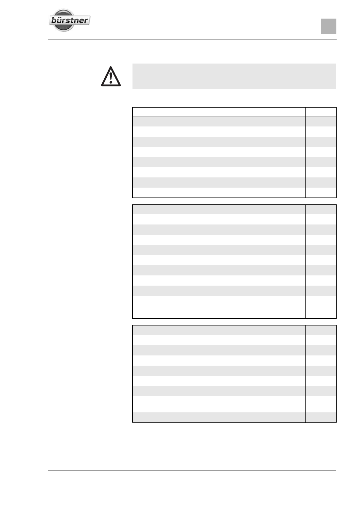
3.12 Road safety
Base vehicle
Before the journey
X Check tyre pressure before a journey or every 2 weeks. Wrong tyre
pressure causes excessive wear and can lead to damage or even to tyre
burst. You can lose control of the vehicle (see section 13.7).
Before commencing the journey, work through the checklist:
No. Checks Checked
1 All vehicle documents are on board
2 Tyres in proper condition and tyre pressure correct
3 Vehicle lighting, brake lights and reversing lights function
4 Oil levels for engine, gearbox and power steering controlled
5 Coolant and fluid for windscreen washers filled up
6 Brakes function
7 Brakes react evenly
8 When braking, the vehicle remains in the lane
3
Housing body, outside
Housing body, inside
9 Awning completely retracted
10 Roof free of snow and ice (in winter)
11 External connections and lines disconnected and stored away
12 External supports removed
13 Fitted supports retracted and fixed in place
14 Wheel chocks removed and stored away
15 Entrance step is stored securely or retracted
16 External flaps closed and locked
17 Conversion door locked
18 Overall height of the vehicle including roof rack when loaded
measured and noted. Keep the height information close at
hand in the driver's cabin
19 Windows and skylights closed and locked
20 Flat screen secured
21 Satellite antenna retracted (if built in)
22 Loose parts and add-on parts stored away or fixed in position
23 Open storage spaces empty
24 Store sink and drain basin covers securely
25 Refrigerator door secured
26 Refrigerator set to 12 V operation (only required in case of
manual power selection)
27 All drawers and flaps closed
33T-Modell - 17/18 - Ausgabe 09/17 - 2891569 - BUE-0029-19EN
Page 34
3
Before the journey
No. Checks Checked
28 All doors secured
29 Pull-down bed secured in top end position
30 Children's seats mounted to seats with three-point safety belts
31 Swivel seat locking device for driver's seat and front passen-
ger's seat locked
32 Shades in the driver's cabin opened and secured
Gas system
Electrical system
33 Gas bottles firmly fixed in the gas bottle compartment so that
they are unable to turn
34 If the gas bottles are not connected to the gas tube, always
place the protective cap on top
35 If there is no supplied crash protection unit: Regulator tap on
the gas bottle and gas isolator taps are closed
36 Check the battery voltage of the starter and living area battery
(see chapter 8). If the panel indicates that the battery voltage
is too low, the respective battery will need to be recharged.
Observe the notes and instructions in chapter 8
Z Commence journey with fully charged starter and
living area batteries.
34 T-Modell - 17/18 - Ausgabe 09/17 - 2891569 - BUE-0029-19EN
Page 35
During the journey
4
Chapter overview
This chapter contains instructions on how to drive the motorhome.
4.1 Driving the motorhome
X The base vehicle is a commercial vehicle (small truck). Adjust your
driving technique accordingly.
X Before commencing the journey and after short interruptions of the
journey, ensure that the entrance step is completely retracted.
X A seat belt is fitted for each seat which is permitted for travel. Please
keep your seat belt fastened during the journey.
X Never open your seat belts when travelling.
X Passengers must remain in the seats provided.
X The doors must remain locked.
X Avoid braking with a jerk.
X If a navigation system is used, only change the destination when the
vehicle is stationary. Drive to a car park or stop in a safe area when
changing the destination.
X Do not play DVDs using the monitor of the navigation system during the
journey.
X Always switch off outdoor light/awning light during the journey.
4During the journey
Z Drive slowly on poor roads.
Z Take extreme care when driving onto ferries, crossing uneven roads and
driving in reverse. Because of the relatively large overhang, larger vehicles
might swing out and "touch ground" in unfavourable conditions. This can
cause damage to the underbody or to parts fitted there.
Z If an accident occurs as a result of these instructions not being observed,
the manufacturer will not be responsible for damages caused.
Z The safety measures stipulated in chapter 2 have to be observed.
Z If a reversing camera is installed in the vehicle, the camera is automatically
switched on when driving in reverse gear.
35T-Modell - 17/18 - Ausgabe 09/17 - 2891569 - BUE-0029-19EN
Page 36
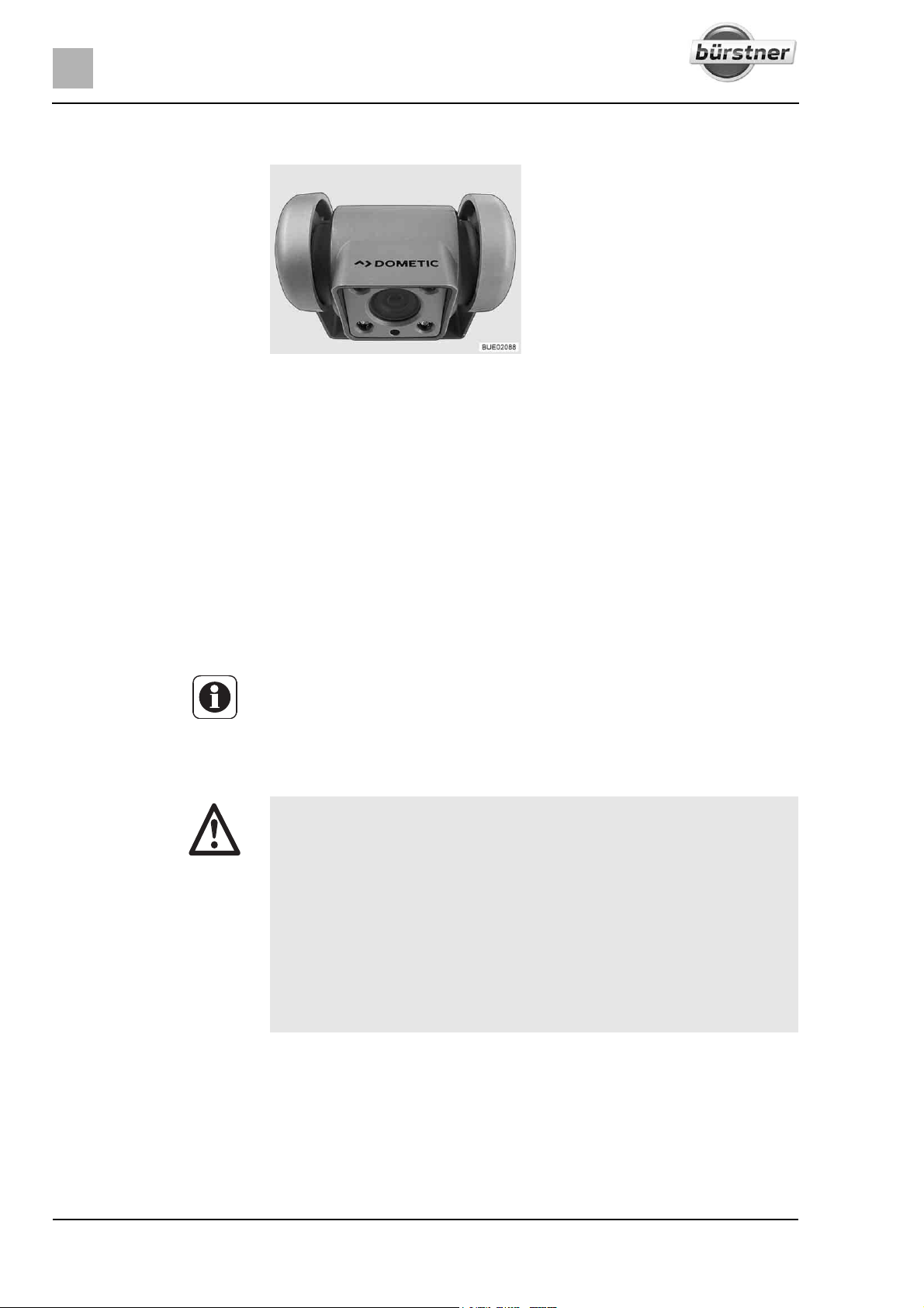
4
During the journey
4.2 Reversing camera (special equipment)
Fig. 20 Reversing camera with
A reversing camera (Fig. 20) is installed in the vehicle.
When it is dark, the infrared LEDs of the reversing camera illuminate the field
of view.
The image of the reversing camera is fed into the central multimedia/navigation system and shown on the existent LCD monitor.
If the engine is running or the ignition is switched on, the reversing camera and
LCD monitor switch themselves on automatically when you engage reverse.
If the engine is running or the ignition is switched on, the reversing camera and
LCD monitor can also be switched on manually via a pushbutton or a switch
on the display.
The system can be switched off via an operating button or via a button on the
display.
Z Further information can be obtained in the manufacturer's instruction
infrared illumination
manual.
4.3 Driving speed
X The vehicle is equipped with a powerful engine. This means there are
sufficient reserves in difficult traffic situations. This high power enables
a high maximum speed and requires above-average driving ability.
X The vehicle provides a large contact surface for wind. A sudden cross-
wind can be especially dangerous.
X Uneven or one-sided loading affects road performance.
X Driving on unknown streets, you may encounter hazardous road condi-
tions and unexpected driving situations. Therefore, in the interest of
safety, make sure your driving speed is appropriate to any given driving
situation and environment.
X Adhere to the national legal speed limits.
36 T-Modell - 17/18 - Ausgabe 09/17 - 2891569 - BUE-0029-19EN
Page 37
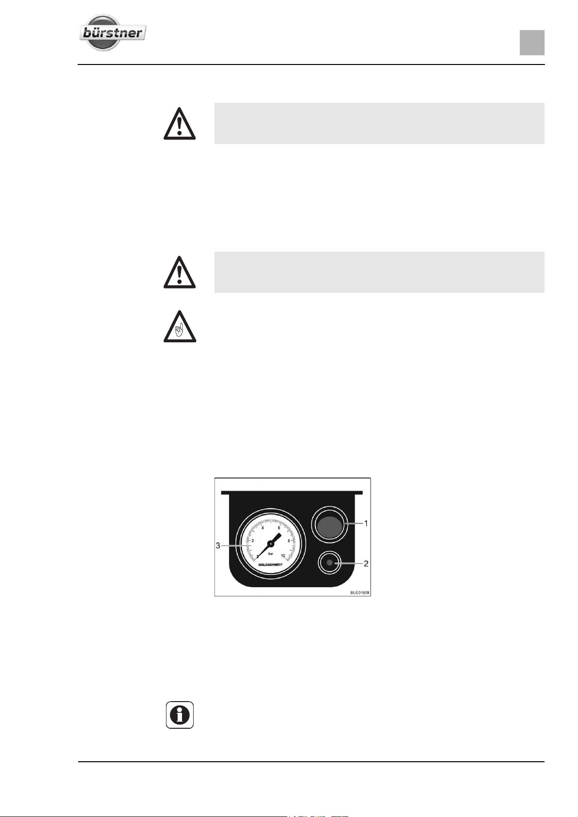
During the journey
4.4 Brakes
X Have defects on the braking system immediately remedied by an author-
ised specialist workshop.
Before each journey Before each journey, check by means of a braking test:
z Do the brakes function?
z Do the brakes react evenly?
z Does the vehicle remain in the lane when braking?
4.5 Air suspension Goldschmitt (special equipment)
X Make sure that no persons are staying underneath the vehicle or
between the wheels when the vehicle is lowered.
Z Do not overload the vehicle (do not exceed the axle load nor the permis-
sible gross weight).
Z Make sure that it is possible to lower the vehicle can be freely even after a
longer stationary period.
Z Before setting of, check the system pressure at the pressure gauge. The
system pressure shall be within a range from 1 to 6 bar. If required,
increase the pressure or decrease the pressure.
Z When using snow chains: make sure that there is sufficient free space for
the snow chains.
4
1-circuit system In addition to the standard equipment of the vehicle with steel springs, two bel-
lows are installed on the rear axle. With that, the vehicle can be lifted several
centimetres.
1 On/Off button
2 Bleeding pin
3 Pressure gauge
Fig. 21 Electrical control unit
Raising the vehicle:
Lowering the vehicle:
Press On/Off button (Fig. 21,1) on the electrical control unit. Fill the system
with an external compressor through a valve (on the left side of the lefthand vehicle seat console).
Release the pressure. In order to do this, press the bleeding pin (Fig. 21,2)
on the electrical control unit.
Z Distribute the load evenly on the bellows because otherwise tensions may
occur on the body. Tensions may hinder opening and closing the doors and
flaps.
Z Also read the manufacturer's instruction manual.
37T-Modell - 17/18 - Ausgabe 09/17 - 2891569 - BUE-0029-19EN
Page 38
4
During the journey
4.6 Seat belts
4.6.1 General
The vehicle is equipped with seat belts in the living area on the seats for which
seat belts are compulsory by law. National regulations apply seat-belt fastening.
X Fasten your seat belts before the beginning of the journey and keep
them fastened during the journey.
X Do not damage or trap belts. Have damaged seat belts changed by an
authorised specialist workshop.
X Do not alter the belt fixing devices, automatic seat belt winders and the
belt clips.
X Only use one seat belt for one adult person.
X Do not belt in objects together with persons.
X Seat belts are not sufficient for persons who are less than 150 cm tall. In
these cases use additional restraining devices. Observe test certificate.
X Only attach the child restraint system to seats that are specified for this
purpose.
X After an accident, replace the seat belts.
X During the journey, do not tilt the backrest too far backwards. Otherwise
the functionality of the seat belt is no longer guaranteed.
4.6.2 Fastening the seat belt correctly
X Do not twist the belt. The belt must be positioned smoothly against the
body.
X When fastening the seat belt, adopt the correct sitting position.
The seat belt is correctly fastened when the lap belt passes below your
stomach and across the hip bone. The shoulder belt must pass across the
chest and shoulder (not across your neck). The belt must always be taut
against your body. Any bulky or padded clothing should therefore be removed
before you start your journey.
38 T-Modell - 17/18 - Ausgabe 09/17 - 2891569 - BUE-0029-19EN
Page 39
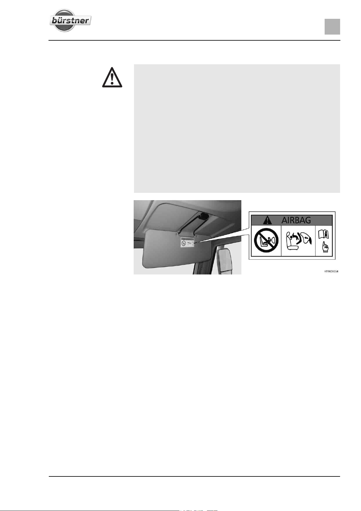
4.7 Child restraint systems
X When travelling, secure children under 13 years of age that are smaller
than 150 cm, with a suitable and officially approved child restraint
system.
X Only attach the child restraint system to seats that are specified for this
purpose. We strongly recommend to install child restraint systems preferably in the second row of seats.
X Fasten the childrens' seat belts before commencing the journey and
make sure that their seat belts are kept fastened during the journey.
X Use a rear-facing child restraint system ("reboard system") only when
the front and side air bags on the passenger side are switched off.
Observe the separate operating instructions of the chassis manufacturer
and the warning notices in the vehicle. If no rear-facing child restraint
system is in use, switch the airbags back on again.
X Never use rearward-facing child restraint system on a seat with acti-
vated front airbag. This may lead to death or to serious injuries in children.
During the journey
4
Rearward-facing child
restraint systems on the
front passenger's seat
Fig. 22 Warning notice on child restraint system (front passenger's seat sun visor)
The front passenger's seat is equipped with an airbag. When this airbag is activated, it is not permitted to use a rearward-facing child restraint system on the
front passenger's seat. In the event of an accident, the triggered airbag may
cause serious injuries in the child or to its death. A warning notice (Fig. 22)
depicting this hazard is attached to both sides of the sun visor.
The airbag of the front passenger's seat can be deactivated. Refer to the
instruction manual of the base vehicle for instructions.
39T-Modell - 17/18 - Ausgabe 09/17 - 2891569 - BUE-0029-19EN
Page 40
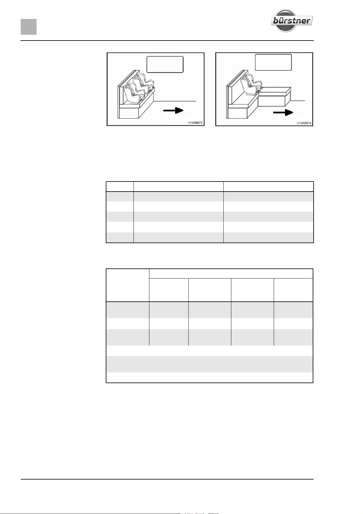
4
During the journey
Fig. 23 Child seats on bench Fig. 24 Child seat on L-shaped bench
The arrow in Fig. 23 and Fig. 24 shows the direction of travel.
On the L-shaped bench, the back cushion on the side wall must be removed
when a child seat is fitted.
Child restraint systems are divided into five classes:
Class Body weight Approximate age
0 Up to 10 kg Up to 9 months
0+ Up to 13 kg Up to 18 months
I 9 kg to 18 kg 9 months to 4 years
II 15 kg to 25 kg 3 years to 7 ½ years
III 22 kg to 36 kg 6 years to 12 years
The following table shows, which child restraint systems can be used on which
seats.
Seats Age groups
< 10 kg
(0-9
months)
Front passen-
X
ger's seat
Bench Fig. 23
L-shaped
2)
U
2) 3)
U
bench Fig. 24
Here, the following meanings apply:
U: Suitable for "universal" restraint systems which are authorised for this age
group.
X: Seat is not suitable for children in this age group.
1)
This only applies without airbag or with deactivated airbag.
2)
Only possible in the respective seat if the distance between the seat and the table
is large enough or if the table has been removed.
3)
Back cushion on side wall removed.
< 13 kg
(0-24
months)
U
1)
9-18 kg
(9-48
months)
U
1)
U U U
3)
U
3)
U
15-36 kg
(4-12 years)
1)
U
3)
U
40 T-Modell - 17/18 - Ausgabe 09/17 - 2891569 - BUE-0029-19EN
Page 41
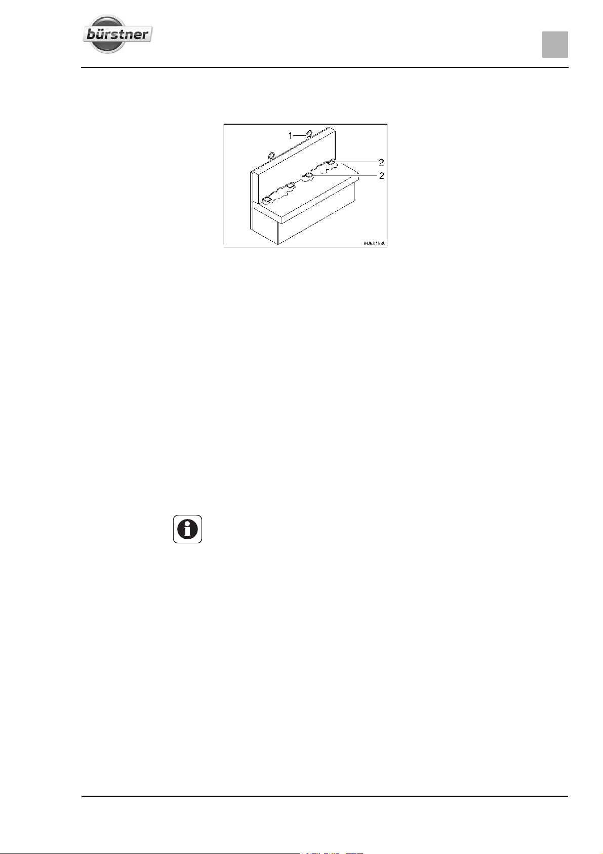
During the journey
4.8 ISOFIX child safety seat mounting system (special equipment)
4
Fastening a child seat
Fig. 25 ISOFIX child safety seat
mounting system
If the vehicle is equipped with the ISOFIX child safety seat mounting system,
the vehicle seats suitable for it are marked with the ISOFIX symbol. These
vehicle seats have retaining brackets (Fig. 25,2) and another anchorage point
at the top of the seat backrest (Top Tether) (Fig. 25,1). Use child restraint
system suitable for ISOFIX. The child restraint systems possess connectors
which are latched to the retaining brackets of the vehicle seat.
The bench with the special equipment ISOFIX child safety seat mounting
system is suitable for child seats with ISOFIX system, which are specially
authorised for this vehicle type according to the standard ECE-R 44.
Child restraint systems of the groups 0, 0+, and 1 with ISOFIX child safety seat
mounting system can be fastened at the ISOFIX anchorage points on the
bench.
Push the connectors of the child seat into the ISOFIX anchorage points
until they engage audibly.
By pulling the child seat, check whether both sides have engaged correctly.
If possible, fasten the child seat at the Top Tether (Fig. 25,1).
Z Also observe the instruction manual of the child restraint system manufac-
turer.
41T-Modell - 17/18 - Ausgabe 09/17 - 2891569 - BUE-0029-19EN
Page 42
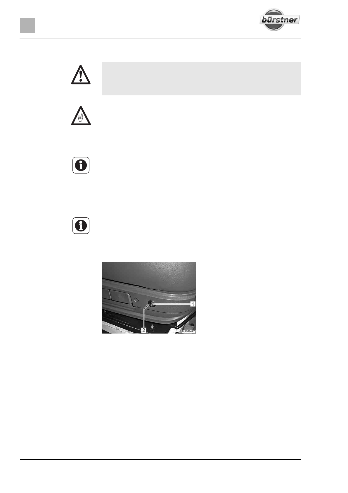
4
During the journey
4.9 Pilot seats for the driver's and front passenger's seats
X Before commencing the journey, rotate all swivel seats in the direction
of travel and lock in position.
X The seats must remain fixed in position during the journey and are not
to be rotated.
Z Before rotating the seats in the pitched vehicle, always apply the hand-
brake.
Z Push the driver's seat into the central position before rotating it. If the
driver's seat is in the very back or in the very front, there is a risk of colliding
with the handbrake lever or the seating group when rotating the driver's
seat.
Z The driver's seat and the front passenger's seat are part of the base
vehicle. The adjustment of the seats is described in the instruction manual
of the base vehicle.
Z The possibilities of seat adjustment differ according to the model and
equipment variants.
4.10 Seat heater (special equipment)
Switching on the seat
heater:
Z The seat heater only works when the ignition is switched on.
Depending on equipment levels, the driver's seat and the front passenger's
seat may have a 2-level seat heater.
Fig. 26 Switch for seat heater
Press the switch (Fig. 26,1) at the back on the left side of the seat console.
z For minimal heating: Press the switch so that it is in the down position.
z For the highest heat level: Press the switch so that it is in the up position.
The LED (Fig. 26,2) comes on when the seat heater is in use.
Switching off the seat
heater:
42 T-Modell - 17/18 - Ausgabe 09/17 - 2891569 - BUE-0029-19EN
Set switch (Fig. 26,1) to the middle position. The LED goes out.
Page 43
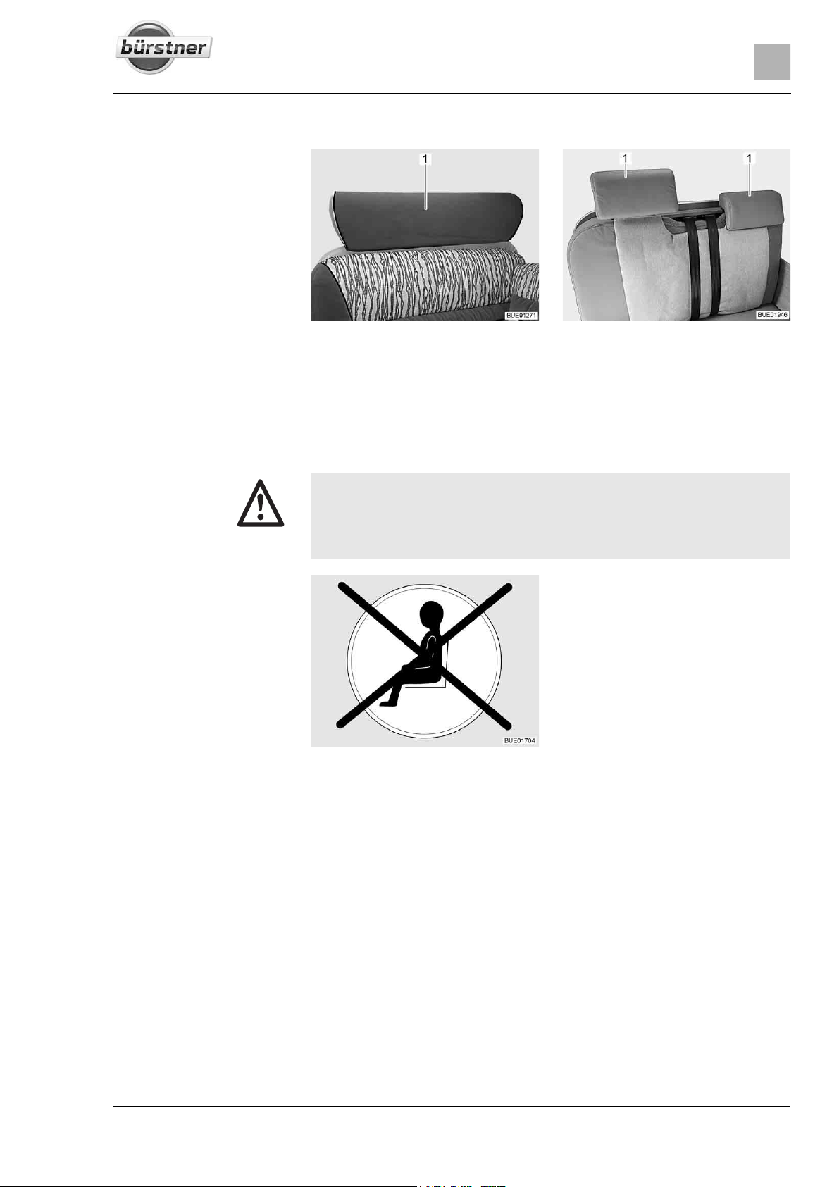
4.11 Headrests
Fig. 27 Bench headrest, one-part Fig. 28 Bench headrest, two-part
Before commencing the journey, adjust the headrest (Fig. 27,1 or Fig. 28,1) so
that the back of the head is supported at approximately ear height.
Push the headrests upwards or downwards by hand.
4.12 Seating arrangement
During the journey
4
X During the journey, persons are only to sit on the permitted seats. The
authorised number of seats is stipulated in the vehicle documents.
X During the journey sitting on the divans is not permitted.
X Seat belts must be worn by all passengers.
Fig. 29 Symbol "Do not use seat
Seats which may not be used during the journey are equipped with a sticker
(Fig. 29).
during the journey"
43T-Modell - 17/18 - Ausgabe 09/17 - 2891569 - BUE-0029-19EN
Page 44
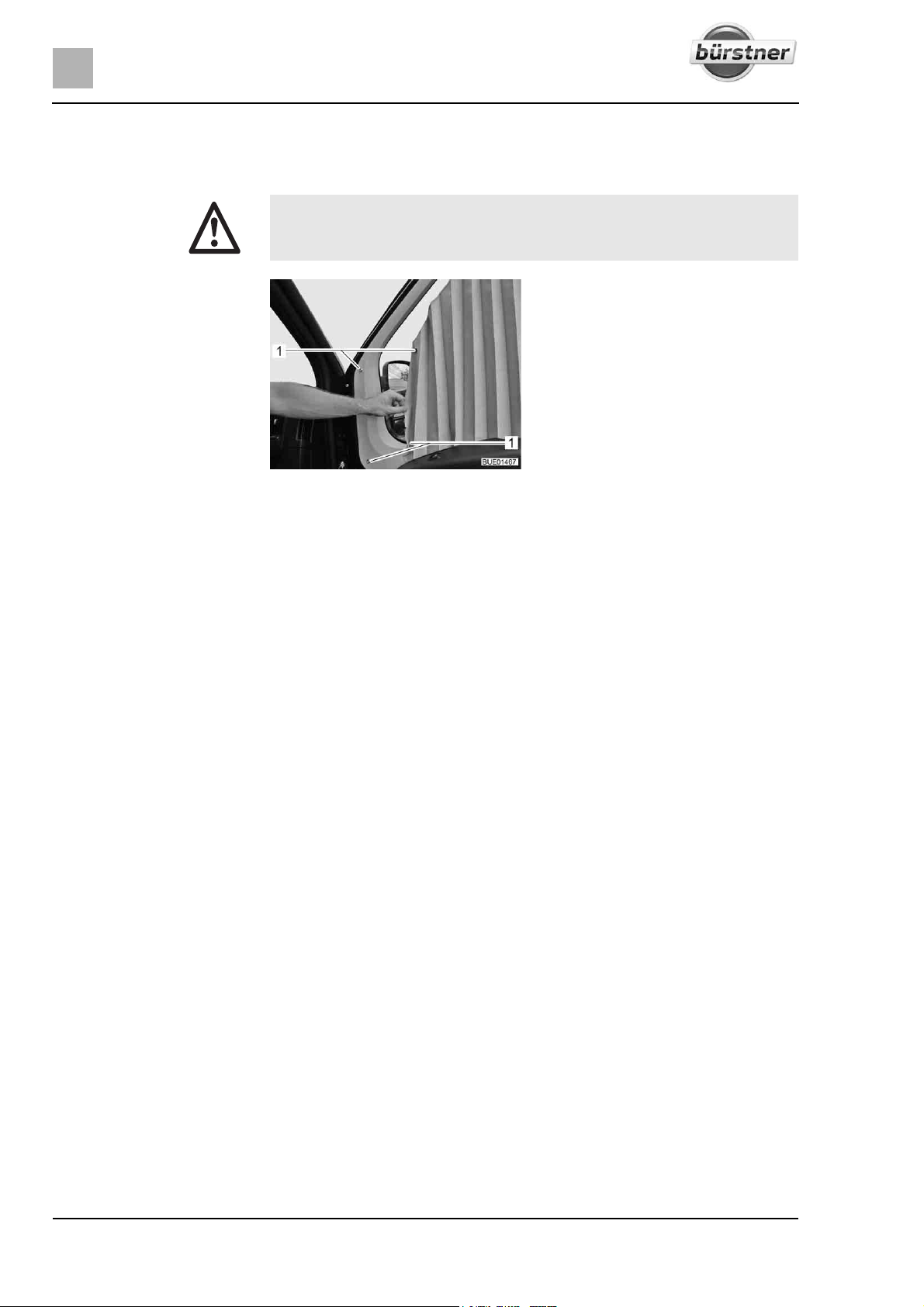
4
During the journey
4.13 Roman shade in the driver's cabin
4.13.1 Pleated Roman shades
X When on the move, the Roman shades for the windscreen, driver's
window and the front passenger's window respectively must be completely removed.
Fig. 30 Pleated Roman shades
Removing the pleated
shade:
Open the snap fasteners (Fig. 30,1), loosen the magnetic strips and detach
the pleated shade from the window (shown here on the passenger
window).
Stow away the pleated shades in the living area.
44 T-Modell - 17/18 - Ausgabe 09/17 - 2891569 - BUE-0029-19EN
Page 45
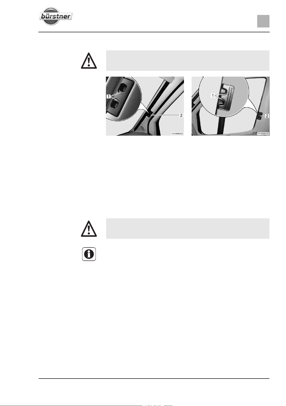
During the journey
4.13.2 Roman shades, Remis (partially special equipment)
X While travelling, the Roman shades for the windscreen, driver's window
and front passenger's window must be open, in a fixed position and
secured.
4
Fig. 31 Roman shade for the wind-
screen
Securing: Use the handle (Fig. 31,2) to pull the two halves of the Roman shade for
the windscreen outwards as far as they will go. When doing so, move the
handle horizontally in the direction of the locking recess.
Allow the release handles (Fig. 31,1) to engage.
Use handle (Fig. 32,2) to push in the Roman shades for the driver's and
passenger's window as far as possible.
Allow the release handles (Fig. 32,1) to engage.
Fig. 32 Roman shade for driver's and
passenger's window
4.14 Refuelling
X All gas-operated devices must be switched off for refuelling (heater,
cooker, oven, grill, refrigerator - depending on the equipment). Danger
of explosion!
Z The fuel filler neck is part of the base vehicle.
Z The fuel filler neck is labelled with the word "Diesel".
Refer to the instruction manual for the base vehicle for the position of the fuel
filler neck.
45T-Modell - 17/18 - Ausgabe 09/17 - 2891569 - BUE-0029-19EN
Page 46
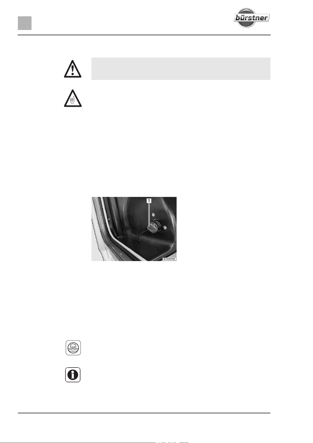
4
During the journey
4.15 Topping up AdBlue® (Citroen base vehicle)
X Store AdBlue
®
out of the reach of children. Do not store any AdBlue®
containers in the vehicle.
Z If the AdBlue
driven until the AdBlue
®
tank is empty, you cannot start the vehicle. If you have
®
tank has been emptied, the tank must be filled with
at least 3.8 litres.
Z Do not dilute AdBlue
Z Do not top the fuel tank up with AdBlue
®
with water.
®
.
The Citroen base vehicle is equipped with an emission control system that
®
operates with the additive AdBlue
of various sizes or at petrol stations that have an AdBlue
The additional tank for AdBlue
. AdBlue® can be purchased in containers
®
dispenser system.
®
has a capacity of 15 litres. Audible and visual
signals indicate when the reserve has been reached. The first alarm appears
when you can still drive 2400 km.
®
The AdBlue
- tank's filler neck is located underneath the fuel tank's filler neck.
The filler neck is closed with a blue lid.
Topping up AdBlue
Fig. 33 Filler neck for AdBlue
®
: Turn blue lid (Fig. 33,1) in an anticlockwise direction and remove it.
Top AdBlue
Place blue lid on filler neck and turn in a clockwise direction as far as it will
®
up from container or dispenser system.
®
go.
Immediately remove any liquid that has possible been spilled around the
filler neck with a moist cloth.
Before the next start of the engine, switch ignition on for approx. 10 sec-
onds without starting the engine while doing so.
Z Do not dispose of the AdBlue
®
containers in the domestic waste. Dispose
of the empty containers in accordance with the national directives or return
them to the point of sale.
Z Further information can be found in the instruction manual of the base
vehicle.
46 T-Modell - 17/18 - Ausgabe 09/17 - 2891569 - BUE-0029-19EN
Page 47
Pitching the motorhome
5
Chapter overview
This chapter contains instructions on how to pitch the vehicle.
Z Pitch the vehicle so that it is as horizontal as possible. Use ramps where
necessary. Otherwise, the water from the shower tray will not be able to
drain properly.
Z Secure the vehicle to prevent it from rolling.
Z Animals (especially mice) can cause great damage to the interior of the
vehicle. To prevent this from happening, regularly check the vehicle for
damages or animal traces after pitching.
5.1 Handbrake
Firmly apply the handbrake when parking the vehicle.
5.2 Entrance step
Z Observe the instructions in section 3.6.
In order to exit the vehicle, first fully extend the electrically operated entrance
step. Observe the indicator lamp on the dashboard.
5Pitching the motorhome
5.3 Ramps
Z Ramps are not included in the scope of delivery. Different models are avail-
able from accessory shops.
To enable the vehicle to be parked on the level, ramps can be used for height
compensation when the vehicle is parked on a hill or on uneven ground.
5.4 Wheel chocks
When parking the vehicle on slopes or inclines use the wheel chocks.
If the maximum permissible gross weight of the vehicle exceeds 4 tonnes,
wheel chocks must be used when parking on gradients. The wheel chocks are
provided as standard for vehicles with a maximum permissible gross weight
exceeding 4 tonnes.
47T-Modell - 17/18 - Ausgabe 09/17 - 2891569 - BUE-0029-19EN
Page 48
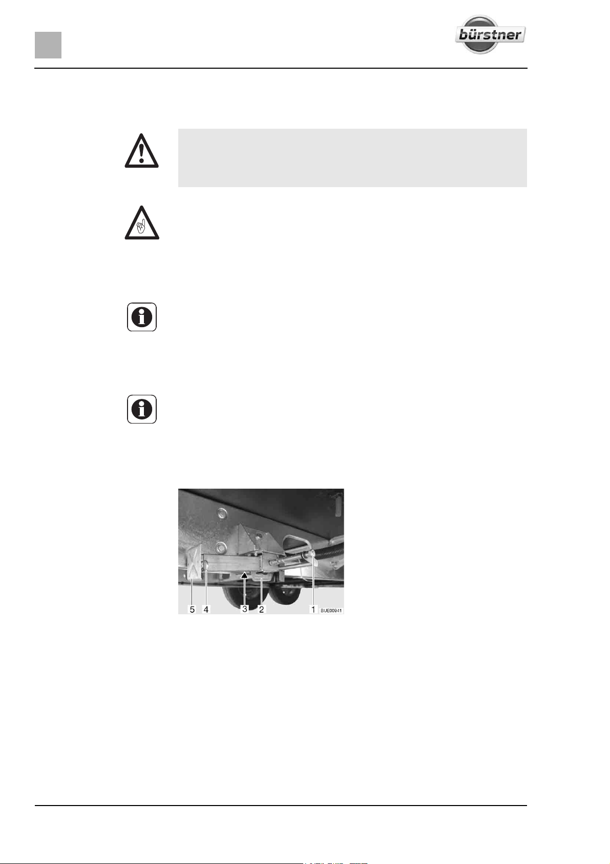
5
Pitching the motorhome
5.5 Supports
5.5.1 General instructions
X The steady legs must not be used to jack up the vehicle in order to work
beneath it, e.g. to change a wheel or carry out maintenance work.
X Whilst the vehicle is in a jacked up position, persons must not lie down
under it.
Z Always apply the handbrake before extending the steady legs.
Z Do not use the fitted supports as a vehicle jack. They supports are only for
stabilising the parked vehicle to prevent the rear axle from bottoming out.
Z When pitching the vehicle, ensure that the supports are evenly loaded.
Z Before driving away, wind up the supports as far as they can go, fully retract
and secure them.
Z When the ground is soft, place a pad or block under the supports in order
to prevent the vehicle from sinking into the ground.
Z Pitch the vehicle so that it is as horizontal as possible. Otherwise, the water
from the shower tray will not be able to drain properly.
5.5.2 Steady legs (special equipment)
Z Depending on the model, the hexagonal nut has a joint, which can be used
to bring the attached socket spanner into a more convenient position for
turning.
In order to ensure their correct function, clean and grease the interior tubes of
the steady legs regularly.
The length of the steady legs can be adjusted according to the model.
Fig. 34 Steady leg
Extending:
Place the socket spanner on the hexagon nut (Fig. 34,1) and rotate until
the steady leg is in a perpendicular downward position.
If the length of the steady leg can be adjusted, remove the splint (Fig. 34,4)
out of the support foot extension (Fig. 34,5).
Pull out the support foot extension until it has reached the required length.
Insert the splint in the support foot extension.
Rotate the hexagonal nut until the steady leg rests completely on the
ground and the vehicle is in a horizontal position.
48 T-Modell - 17/18 - Ausgabe 09/17 - 2891569 - BUE-0029-19EN
Page 49
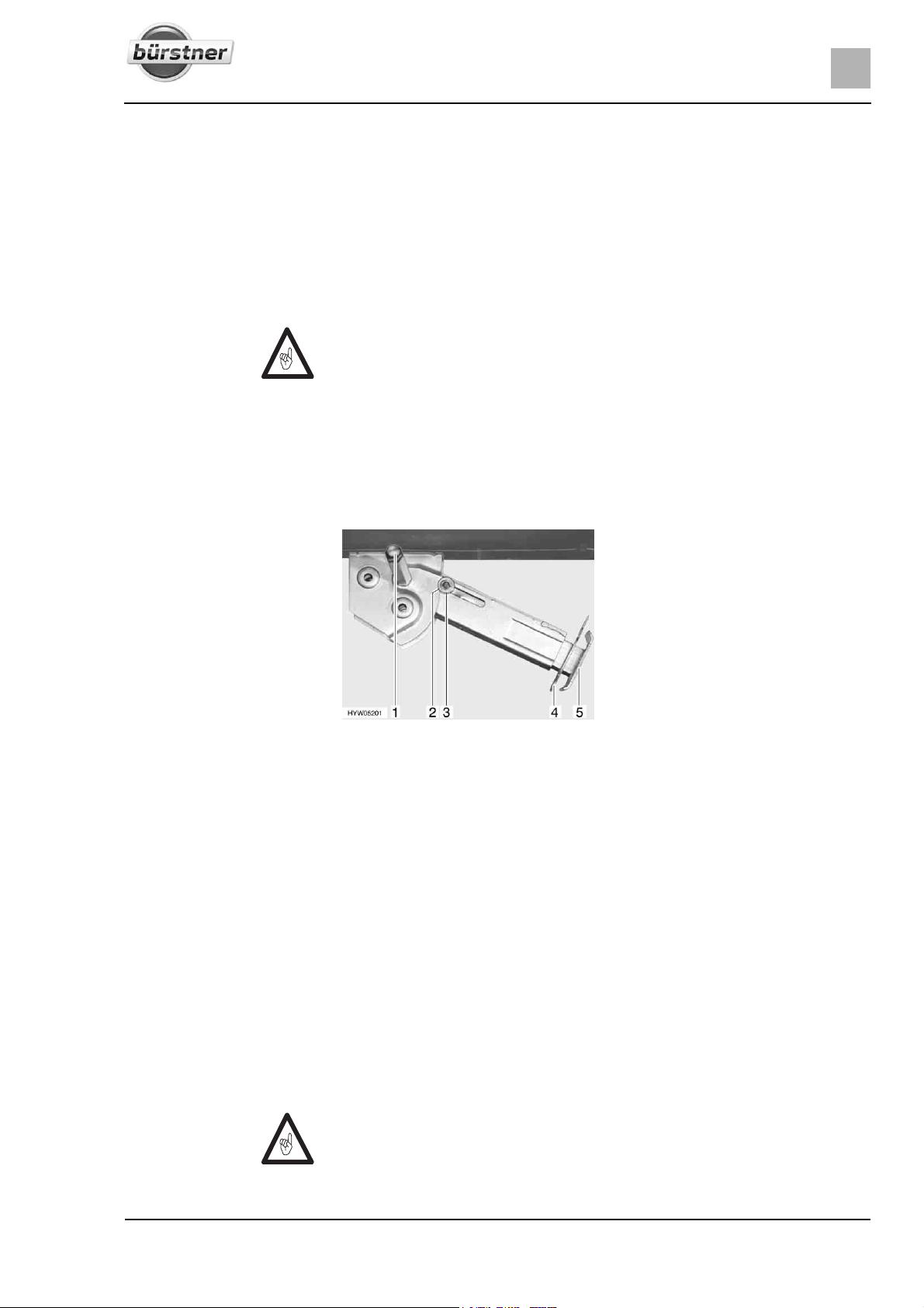
Pitching the motorhome
5
Retracting: Place the socket spanner on the hexagon nut (Fig. 34,1) and rotate until
the steady leg is clear of the ground.
If the length of the steady leg can be adjusted, remove the splint (Fig. 34,4)
out of the support foot extension (Fig. 34,5).
Push in the support foot extension (Fig. 34,5) and insert the splint
(Fig. 34,4) in the drilled hole in the support foot extension.
Rotate the hexagonal nut (Fig. 34,1) until the steady leg has swung
upwards and the guide (Fig. 34,2) has reached the very end of the slot
(Fig. 34,3).
Z Before commencing the journey, observe the following: Are all steady legs
and support foot extensions retracted completely and secured with the
splint?
5.5.3 Steady legs (AL-KO) (special equipment)
In order to ensure their correct function, clean and grease the interior tubes of
the steady legs regularly.
The length of the steady legs can be adjusted according to the model.
Extending:
Retracting:
Fig. 35 Steady leg
Place the socket spanner on the hexagon nut (Fig. 35,1) and rotate until
the steady leg is in a perpendicular downward position.
Remove the splint (Fig. 35,4) out of the support foot extension (Fig. 35,5).
Extend the support foot extension until it has reached the required length.
Insert the splint in the support foot extension.
Rotate the hexagonal nut until the steady leg rests completely on the
ground and the vehicle is in a horizontal position.
Place the socket spanner on the hexagon nut (Fig. 35,1) and rotate until
the steady leg is clear of the ground.
Remove the splint (Fig. 35,4) out of the support foot extension (Fig. 35,5).
Push in the support foot extension (Fig. 35,5) and insert the splint
(Fig. 35,4) in the drilled hole in the support foot extension.
Rotate the hexagonal nut (Fig. 35,1) with the socket spanner until the
steady leg has swung upwards and the guide disc (Fig. 35,3) has completely retracted into the notch (Fig. 35,2).
Z Before commencing the journey, observe the following: Are all steady legs
and support foot extensions retracted completely and secured with the
splint?
49T-Modell - 17/18 - Ausgabe 09/17 - 2891569 - BUE-0029-19EN
Page 50
5
Pitching the motorhome
5.6 230 V connection
The vehicle can be connected to a 230 V power supply (see chapter 8).
5.7 Refrigerator
X If the refrigerator is set to 12 V operation, it will constantly consume cur-
rent. Therefore, switch over to gas operation when the vehicle engine is
not running, and the vehicle is not connected to the 230 V power supply.
In the case of appliances with automatic power selection, the 12 V operation
of the refrigerator will only be selected in the automatic mode when the vehicle
engine is running.
In the case of appliances with manual power selection: When the vehicle
engine is switched off, switch the refrigerator to 230 V operation or gas operation.
5.8 Satellite unit (special equipment)
X Before commencing the journey, ensure that the antenna is in park posi-
tion. Danger of accidents!
Z Move the antenna into parking position in the event of strong wind (above
80 km/h).
Z The vehicle must be still during the satellite search. Do not walk through
the vehicle.
Z Satellite reception is only possible, when the antenna is positioned in direct
line of sight of the chosen satellite and the view is not blocked in any way.
Z Further information can be obtained in the device manufacturer's instruc-
tion manual.
5.8.1 Satellite unit with manual satellite selection (TeleSat)
The selection of the desired satellite is carried out on the operating panel of
the unit. The automatic advance unit ensures that the antenna is precisely
aligned to the desire satellite.
When switching on the unit, the antenna is extended automatically. When
switching off the unit and when starting the vehicle engine, the antenna is
retracted automatically.
The satellite unit is operated via the operating panel. When the antenna is
moving (retracting/extending or satellite search), this is indicated by an animation on the display.
The operating panel changes into standby mode after a few seconds without
any operation.
50 T-Modell - 17/18 - Ausgabe 09/17 - 2891569 - BUE-0029-19EN
Page 51
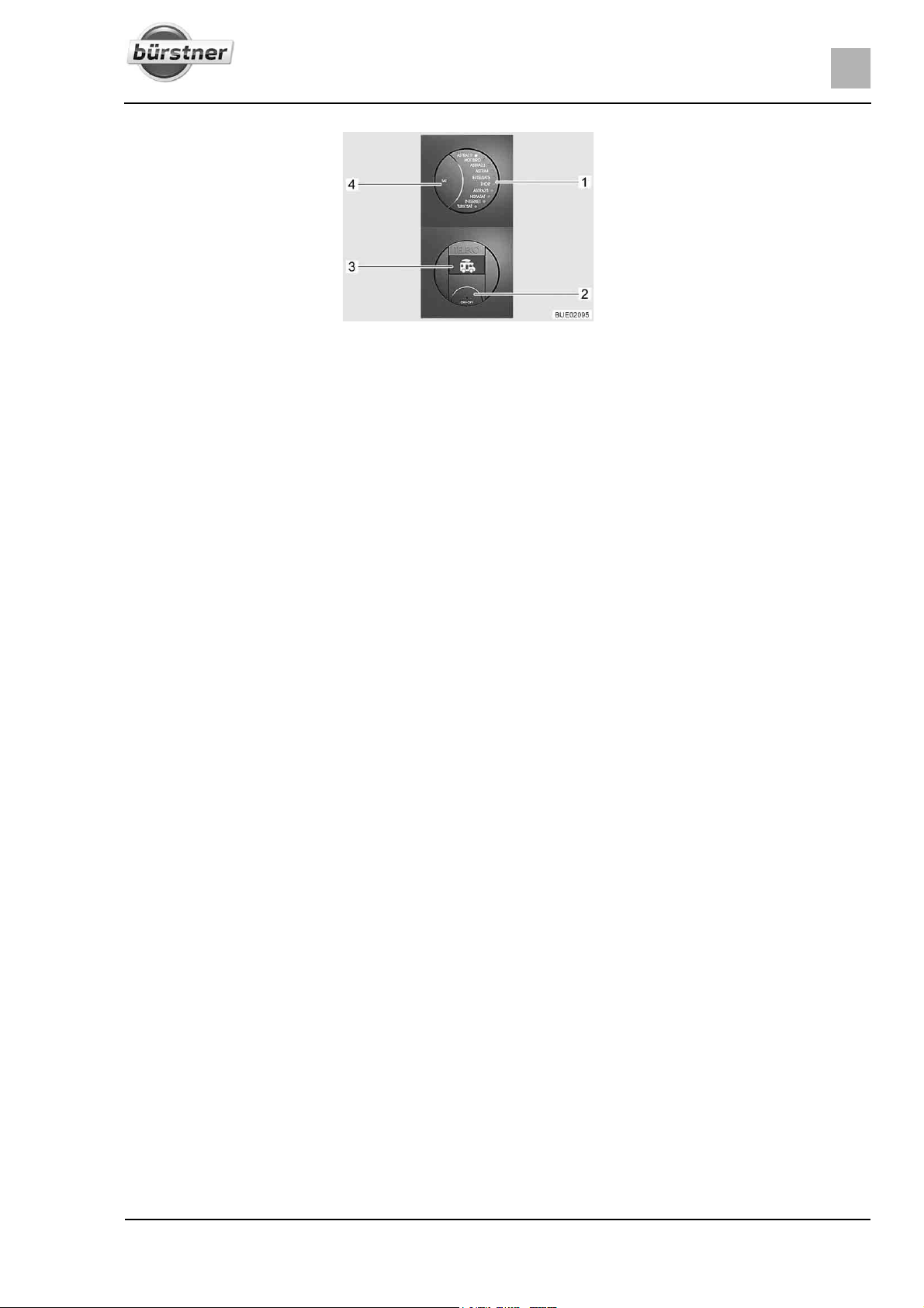
Pitching the motorhome
1 LED indicator of the selected satellite
2 On/Off button
3 Display
4 SAT button
Fig. 36 Operating panel (TeleSat)
Switching on the unit: Press the On/Off button (Fig. 36,2). The LED indicator of the selected sat-
ellite (Fig. 36,1) and the background lighting of the buttons are lit. The
symbol of the vehicle with retracted antenna appears on the display
(Fig. 36,3).
Press the On/Off button (Fig. 36,2) again. The system has been switched
on. If the antenna had been retracted, it will now extend to operating position.
If the LED of the desired satellite (Fig. 36,1) is already flashing, wait a few
seconds. The antenna automatically aligns with this satellite (the last satellite position is saved after switching off).
When the unit has found the satellite, the LED (Fig. 36,1) is lit permanently
and "SAT OK" is shown on the display (Fig. 36,3).
Switch on the SAT receiver and select the desired television channel.
5
Choosing a satellite:
Switching off the unit:
Press the SAT button (Fig. 36,4) repeatedly until the LED (Fig. 36,1) indi-
cates the desired satellite. The antenna automatically aligns with this satellite.
When the unit has found the satellite, the LED (Fig. 36,1) is lit permanently
and "SAT OK" is shown on the display (Fig. 36,3).
Press the On/Off button (Fig. 36,2). The LED indicator of the selected sat-
ellite (Fig. 36,1) and the background lighting of the buttons are lit. The currently selected satellite is shown on the display (Fig. 36,3).
Press the On/Off button (Fig. 36,2) again. The antenna retracts. When the
antenna has been fully retracted, the symbol of the vehicle with retracted
antenna is shown on the display. The system changes to the standby mode
after a few seconds.
51T-Modell - 17/18 - Ausgabe 09/17 - 2891569 - BUE-0029-19EN
Page 52
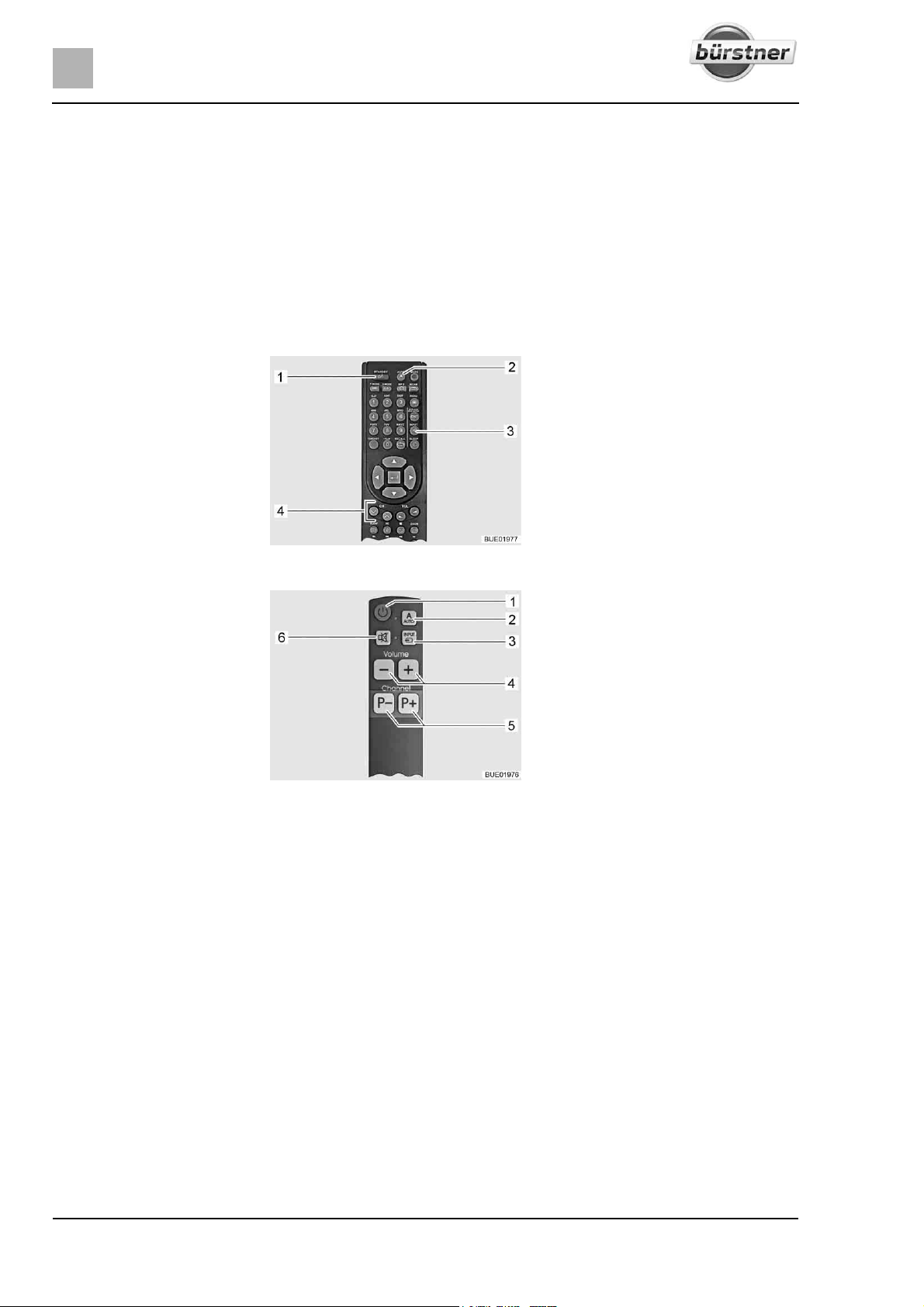
5
Pitching the motorhome
5.8.2 Satellite unit with automatic antenna alignment (Teleco)
The satellite unit is equipped with an automatic advance unit. This automatic
advance unit ensures that the antenna is aligned precisely.
When switching on the unit, the antenna is extended automatically. When
switching off the unit or when starting the vehicle engine, the antenna is
retracted automatically.
When the desired TV programme is chosen, the corresponding satellite is
selected and aimed at automatically.
The satellite unit is operated via remote control. Optionally, a simplified remote
control is available.
1 Television on/off button
2 AUTO button (advance unit and tele-
vision on/off)
3 INPUT button (selection of the signal
source)
4 Programme selection buttons
Switching on the unit:
Choosing a TV programme:
Fig. 37 Remote control
1 Television on/off button
2 AUTO button (advance unit and tele-
vision on/off)
3 INPUT button (selection of the signal
source)
4 Volume buttons
5 Programme selection buttons
6 Mute button
Fig. 38 Simplified remote control
(optional)
Press the AUTO button (Fig. 37,2 or Fig. 38,2) for 1 second. Thus, the tel-
evision and the advance unit are switched on.
If the antenna had been retracted, it will now extend to operating position. The
antenna then automatically starts searching for the satellite suitable for the set
TV programme.
When the unit finds the satellite, the TV programme appears automatically.
Press the programme selection buttons (Fig. 37,4 or Fig. 38,5) until the
desired TV programme has been selected.
The antenna automatically searches for the suitable satellite.
When the unit finds the satellite, the TV programme appears automatically.
Choosing the signal source:
Press the INPUT button (Fig. 37,3 or Fig. 38,3) repeatedly until the desired
signal source has been selected.
To return to the satellite channels display, press the INPUT button
(Fig. 37,3 or Fig. 38,3) repeatedly until the signal source DVB-S2 has been
selected.
52 T-Modell - 17/18 - Ausgabe 09/17 - 2891569 - BUE-0029-19EN
Page 53
Pitching the motorhome
Switching off the unit: Press the AUTO button (Fig. 37,2 or Fig. 38,2).
The antenna automatically moves into parking position. When reaching the
parking position, this is displayed on the screen.
The television and advance unit switch off after a few seconds.
5
Operating the unit without
using the antenna:
5.8.3 Satellite unit with automatic antenna alignment (Oyster
Press the Television on/off button (Fig. 37,1 or Fig. 38,1). The advance unit
is not switched on, the antenna remains in parking position.
Press the INPUT button (Fig. 37,3 or Fig. 38,3) repeatedly until the desired
signal source (e.g. DVD) has been selected.
Press the Television on/off button (Fig. 37,1 or Fig. 38,1) to switch the tel-
evision off.
Premium)
Z In the event of a longer stationary period, disconnect the flat screen from
the power supply with the flip switch to prevent the living area battery from
getting discharged.
Z If the location is adjusted with the help of the list of countries, the satellite
search will be accelerated.
Z If the antenna has been retracted by switching on the ignition, it is required
to restart the system by switching it off and on.
Z The reception of DVB-T/T2 channels (digital terrestrial television) is only
possible if there is a DVB-T/T2 antenna present.
The antenna will automatically be aligned with a pre adjusted satellite if the
receiver system is within the reach of this satellite.
When switching on the unit, the antenna is extended automatically. When
switching off the unit or when starting the vehicle engine, the antenna is
retracted automatically.
When the desired TV programme is chosen, the corresponding satellite is
selected and aimed at automatically.
The remote control's basic operating functions are listed here; refer to the
manufacturer's separate instruction manual for a full description.
The system is equipped in the factory with list of standard channels as well as
lists of favourites. You can change or add to these standard lists manually as
desired.
53T-Modell - 17/18 - Ausgabe 09/17 - 2891569 - BUE-0029-19EN
Page 54
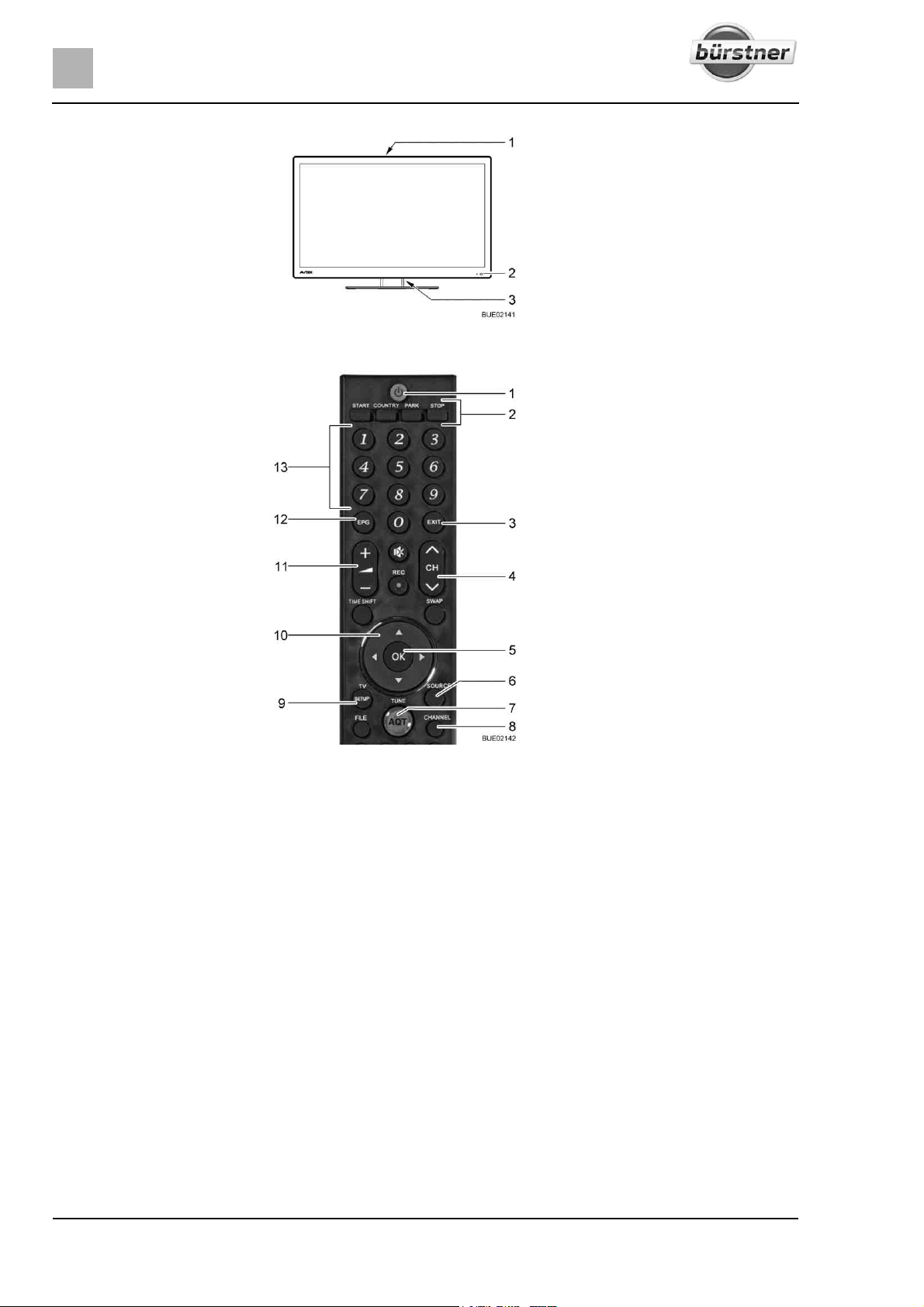
5
Pitching the motorhome
1 Operating buttons on the back of the
device
2 Standby mode/operation LED
3 ON/OFF flip switch
Fig. 39 Operation on the flat screen
1 POWER button
2 Manual control of antenna
3 EXIT button - exit menu without
saving
4 Programme selection button
5 OK button - confirm selection or
save setting
6 SOURCE button - select signal
source
7 AQT button - start DVB-T/T2
channel scan
8 CHANNEL button - call list of chan-
nels
9 SETUP button - call main menu
10 Navigation buttons in the menu
11 Volume button
12 EPG button - programme guide
13 Numeric keys - call programme
channel directly or enter numbers
Fig. 40 Remote control
Switching on the unit: Set flip switch (Fig. 39,3) on the flat screen's back to ON. The system
changes to standby mode. The LED (Fig. 39,2) is lit red.
Further operation is performed via the remote control and the indicators displayed on the flat screen.
Press the POWER button (Fig. 40,1) on the remote control. The LED
(Fig. 39,2) is lit blue.
Choosing a TV programme:
Press the programme selection buttons (Fig. 40,4 or Fig. 40,13) until the
desired TV programme has been selected.
The antenna automatically searches for the suitable satellite.
When the unit finds the satellite, the TV programme appears automatically.
Choosing the signal source:
Press the SOURCE button (Fig. 40,6) repeatedly until the desired signal
source has been selected.
To return to the satellite channels display, press the SOURCE button
repeatedly until the signal source DVB-S has been selected.
54 T-Modell - 17/18 - Ausgabe 09/17 - 2891569 - BUE-0029-19EN
Page 55
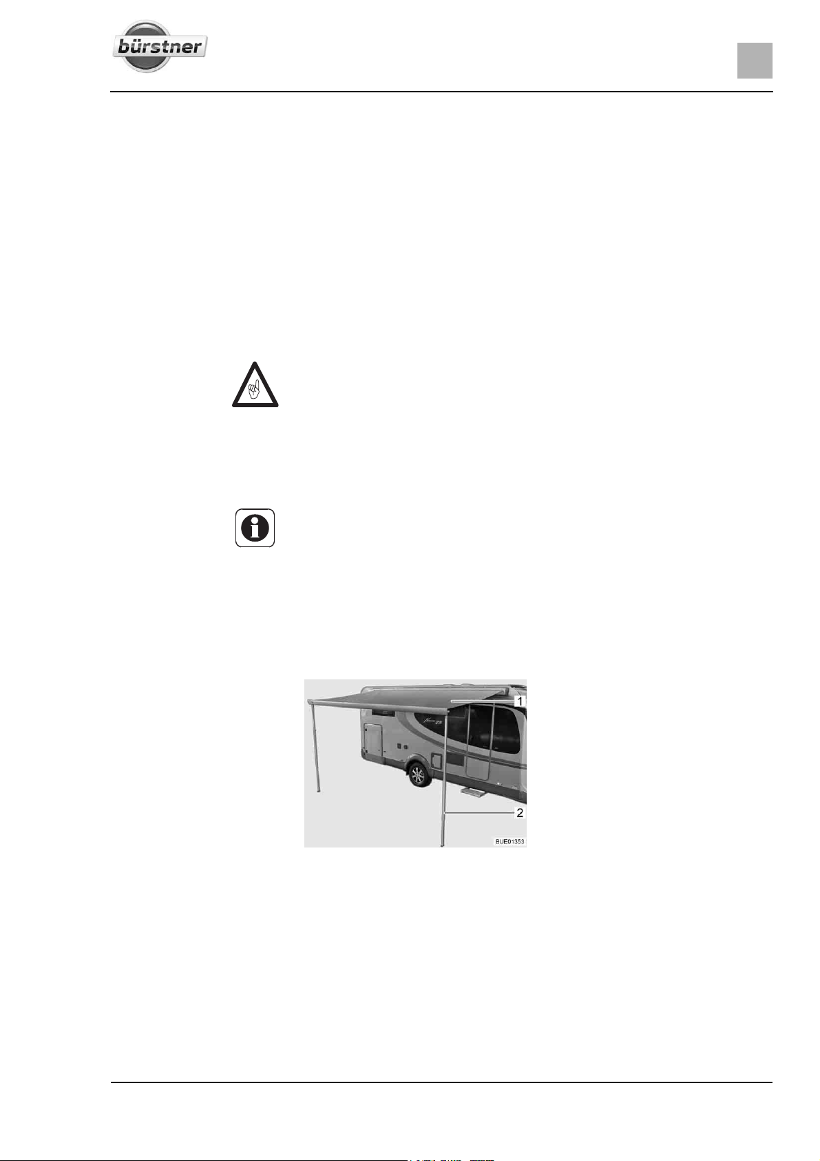
Pitching the motorhome
5
Operating the unit without
using the antenna:
Switching off the unit:
5.9 Awning (special equipment)
Press the PARK button (Fig. 40,2). The antenna moves into parking posi-
tion.
Press the SOURCE button (Fig. 40,6) repeatedly until the desired signal
source (e.g. DVD) has been selected.
Press the POWER button (Fig. 40,1) on the remote control. The system
changes to standby mode. The LED (Fig. 39,2) is lit red.
Set flip switch (Fig. 39,3) on the flat screen's back to OFF.
The system is disconnected from the power supply.
The antenna automatically moves into parking position.
Z Retract the awning in strong wind, rain or snow.
Z In the case of light rain, shorten one of the support legs so that water can
run off.
Z Only retract the awning when the fabric is dry. When the awning must be
retracted while the fabric is still wet: Extend the awning as soon as possible, in order to dry out the fabric.
Z Before retracting, remove leaves and coarse dirt from the awning.
Z Only use the awning for protection against the sun.
Z Also read the manufacturer's instruction manual.
Advantages of the awning The advantages of an awning are:
z The awning provides shade.
z The awning creates a covered vestibule and thus expands the space.
z The vehicle thus becomes more homelike.
z The integrated LED lighting (special equipment) provides additional light.
Fig. 41 Awning
Putting up the awning:
Use the manual crank to open up the awning (Fig. 41,1).
Set up the brackets (Fig. 41,2) when the awning is open.
55T-Modell - 17/18 - Ausgabe 09/17 - 2891569 - BUE-0029-19EN
Page 56

5
Pitching the motorhome
56 T-Modell - 17/18 - Ausgabe 09/17 - 2891569 - BUE-0029-19EN
Page 57
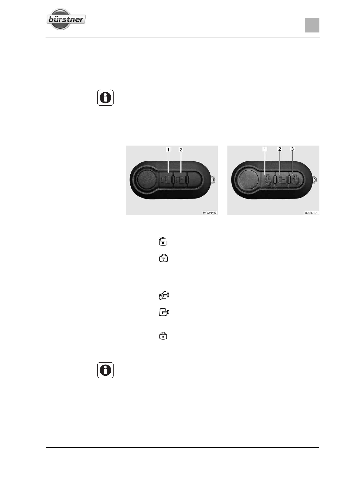
Living
6
Chapter overview
This chapter contains instructions about living in the vehicle.
6.1 Central locking system (special equipment)
Z The central locking mechanism locks the driver's door, the passenger's
door and the conversion entrance door.
Z The central locking system has no function, if the battery cut-off switch on
the transformer/rectifier is switched off.
Z If, after you press the release button, a door is not opened within
40 seconds, the central locking system automatically locks the doors
again.
6Living
Unlocking doors:
Locking doors:
Fig. 42 Remote control for central
locking system (2 buttons)
Press the button (Fig. 42,1) once briefly. The door locks are unlatched.
Press the button (Fig. 42,2) once briefly. The door locks are locked.
Fig. 43 Remote control for central
locking system (3 buttons)
Model with 3 buttons Depending on the equipment, the vehicle will be equipped with a remote con-
trol with 3 buttons.
Unlocking driver's door:
Unlocking conversion door:
Press the button (Fig. 43,1) once briefly. The driver's door is unlocked.
Press the button (Fig. 43,3) once briefly. The conversion door is
unlocked.
Locking all doors:
Press the button (Fig. 43,2) once briefly. All doors have been locked.
If one ore more doors have not been correctly closed, the direction indicators
will be flashing rapidly.
Z Further information can be found in the instruction manual of the base
vehicle.
57T-Modell - 17/18 - Ausgabe 09/17 - 2891569 - BUE-0029-19EN
Page 58
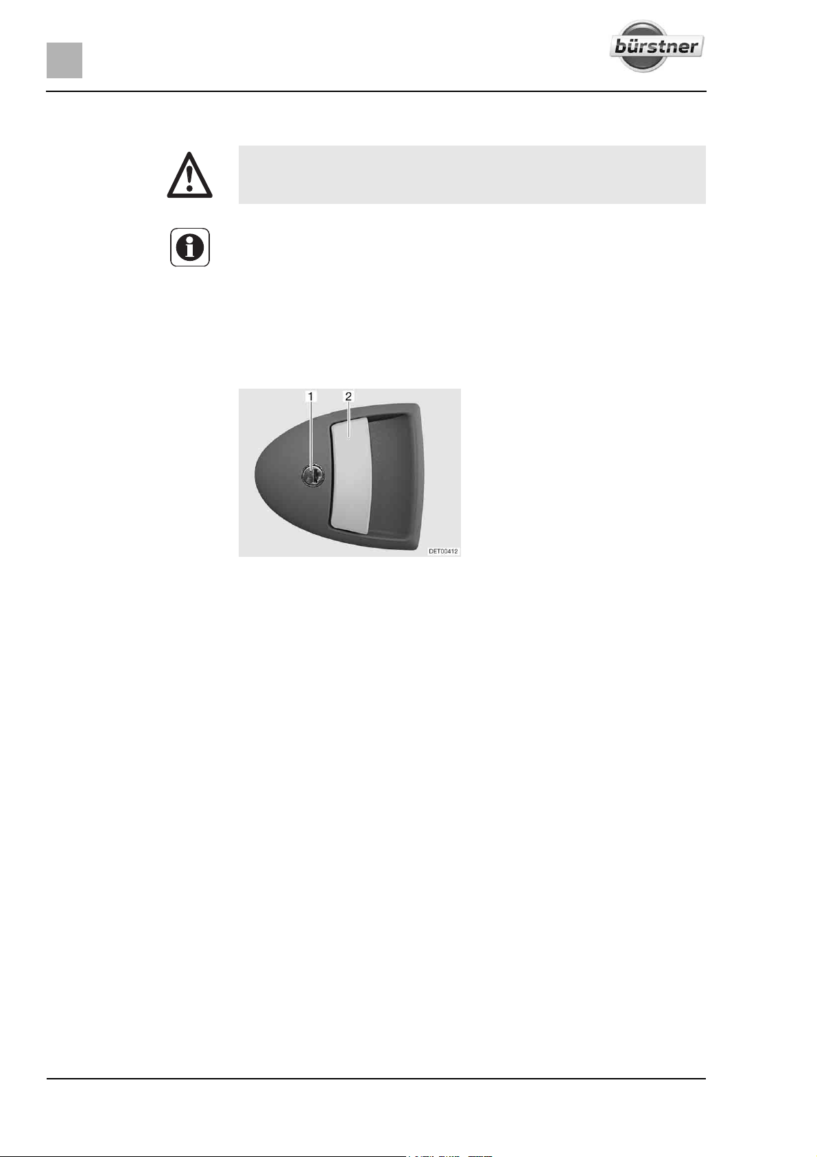
6
Living
6.2 Conversion door
X Only drive with locked doors.
Z Locking the doors can prevent them from opening of their own accord, e.g.
during an accident.
Z Locked doors also prevent forced entry, e.g. when waiting at traffic lights.
However, in an emergency, locked doors make it more difficult for helpers
to enter the vehicle.
Z When leaving the vehicle, always lock the doors.
6.2.1 Conversion door, outside (partially special equipment)
Fig. 44 Door lock of conversion door,
Opening: Insert the key into locking cylinder (Fig. 44,1) and turn until the door lock is
Return the key to the central position and remove it.
Pull on the door handle (Fig. 44,2). The door is open.
Locking:
Insert the key into locking cylinder (Fig. 44,1) and turn until the door lock is
Return the key to the central position and remove it.
outside
unlatched.
engaged.
58 T-Modell - 17/18 - Ausgabe 09/17 - 2891569 - BUE-0029-19EN
Page 59
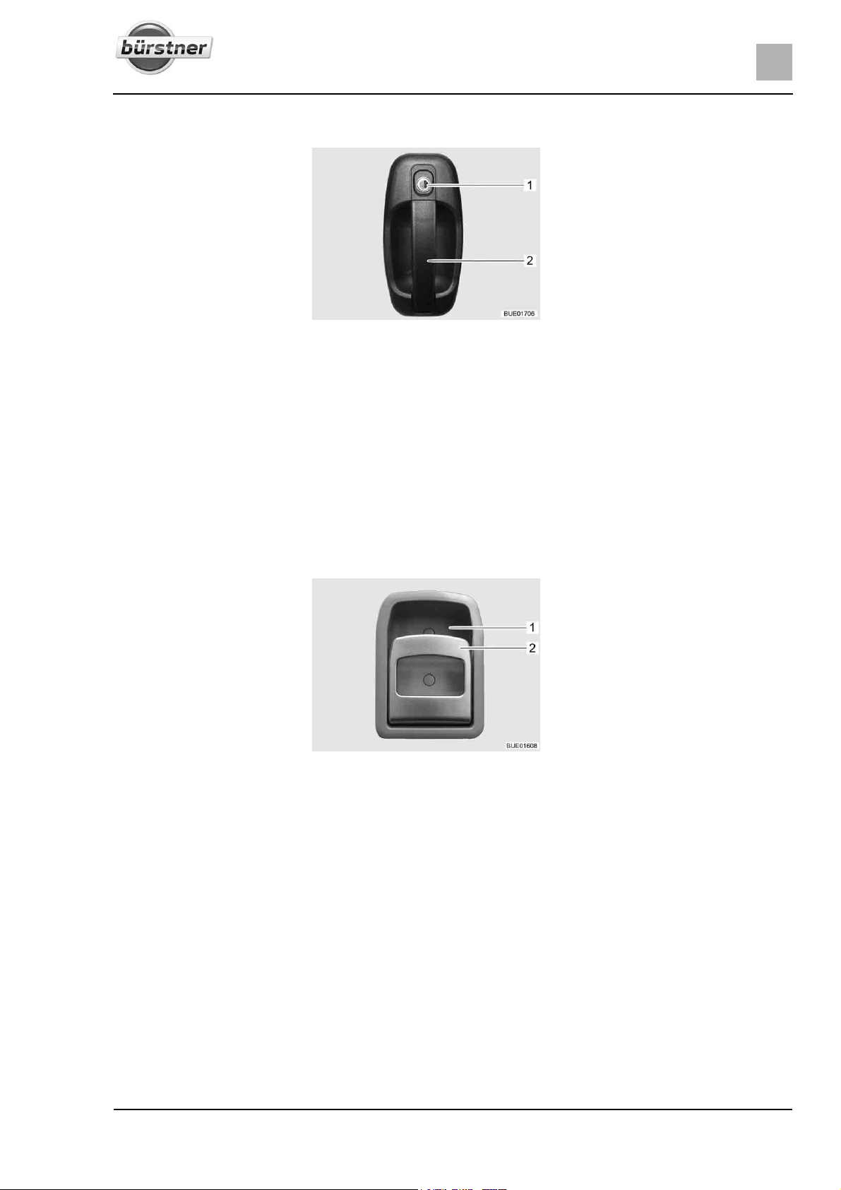
6.2.2 Conversion door, outside
Living
6
Fig. 45 Door lock of conversion door,
Opening: Insert the key into locking cylinder (Fig. 45,1) and turn until the door lock is
Return the key to the central position and remove it.
Pull upper part of the door handle (Fig. 45,2). The door is open.
Locking:
Insert the key into locking cylinder (Fig. 45,1) and turn until the door lock is
Return the key to the central position and remove it.
outside
unlatched.
engaged.
6.2.3 Conversion door, inside
Fig. 46 Door lock of conversion door,
Opening: Pull on the handle (Fig. 46,2). The door lock is unlatched or opened.
Locking:
Press the upper part of the handle (Fig. 46,2) in the direction of the
inside
recessed handle (Fig. 46,1). The door lock is locked.
59T-Modell - 17/18 - Ausgabe 09/17 - 2891569 - BUE-0029-19EN
Page 60
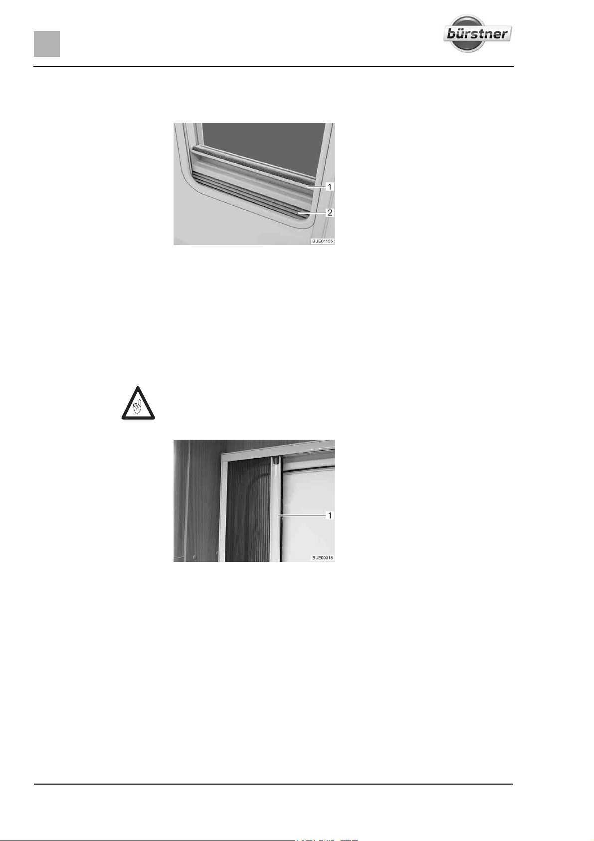
6
Living
6.2.4 Window of conversion door (partially special equipment)
The conversion door window is fitted with a Roman shade.
Fig. 47 Roman shade
Closing:
Opening:
Grip the Roman shade (Fig. 47,2) in the middle of the holding bar
(Fig. 47,1), pull it upwards and then release it at the desired height. The
Roman shade will stay at this height.
Grip the Roman shade in the middle of the holding bar and push it down.
6.2.5 Folding insect screen on the conversion door (partially special equipment)
Z Open the insect screen completely before closing the conversion door.
Fig. 48 Insect screen
Closing: Pull out the insect screen completely by the bar (Fig. 48,1).
Opening:
60 T-Modell - 17/18 - Ausgabe 09/17 - 2891569 - BUE-0029-19EN
Push the insect screen into its initial position by the bar (Fig. 48,1).
Page 61
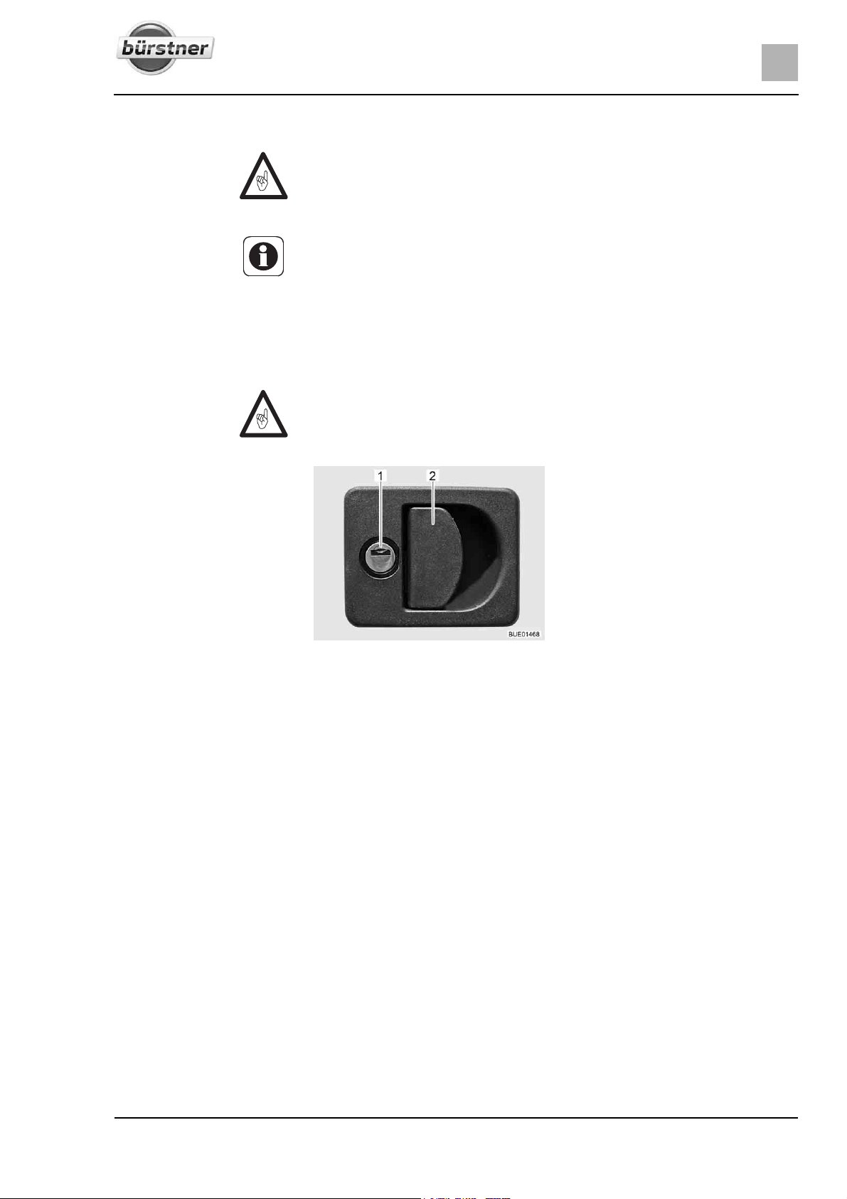
6.3 External flaps
Z Before commencing the journey, close all external flaps and lock them.
Z To open and close the external flap, open or close all locks that are fitted
to the external flap.
Z When leaving the vehicle, close all external flaps.
The external flaps fitted to the vehicle are all fitted with identical locking cylinders. Therefore, all locks can be opened with a single key.
6.3.1 Flap lock with recessed handle
Z To open the external flap, pull all the lock handles fitted to that particular
external flap at the same time.
1 Locking cylinder
2 Lock handle
Living
6
Fig. 49 Flap lock with recessed handle
Opening: Insert key into locking cylinder (Fig. 49,1) and turn a quarter turn. The flap
lock is unlatched.
Remove the key.
Pull on the lock handle (Fig. 49,2). The external flap is open.
Closing:
Firmly close the external flap.
Insert key into locking cylinder and turn a quarter turn. The flap lock is
locked.
Remove the key.
61T-Modell - 17/18 - Ausgabe 09/17 - 2891569 - BUE-0029-19EN
Page 62
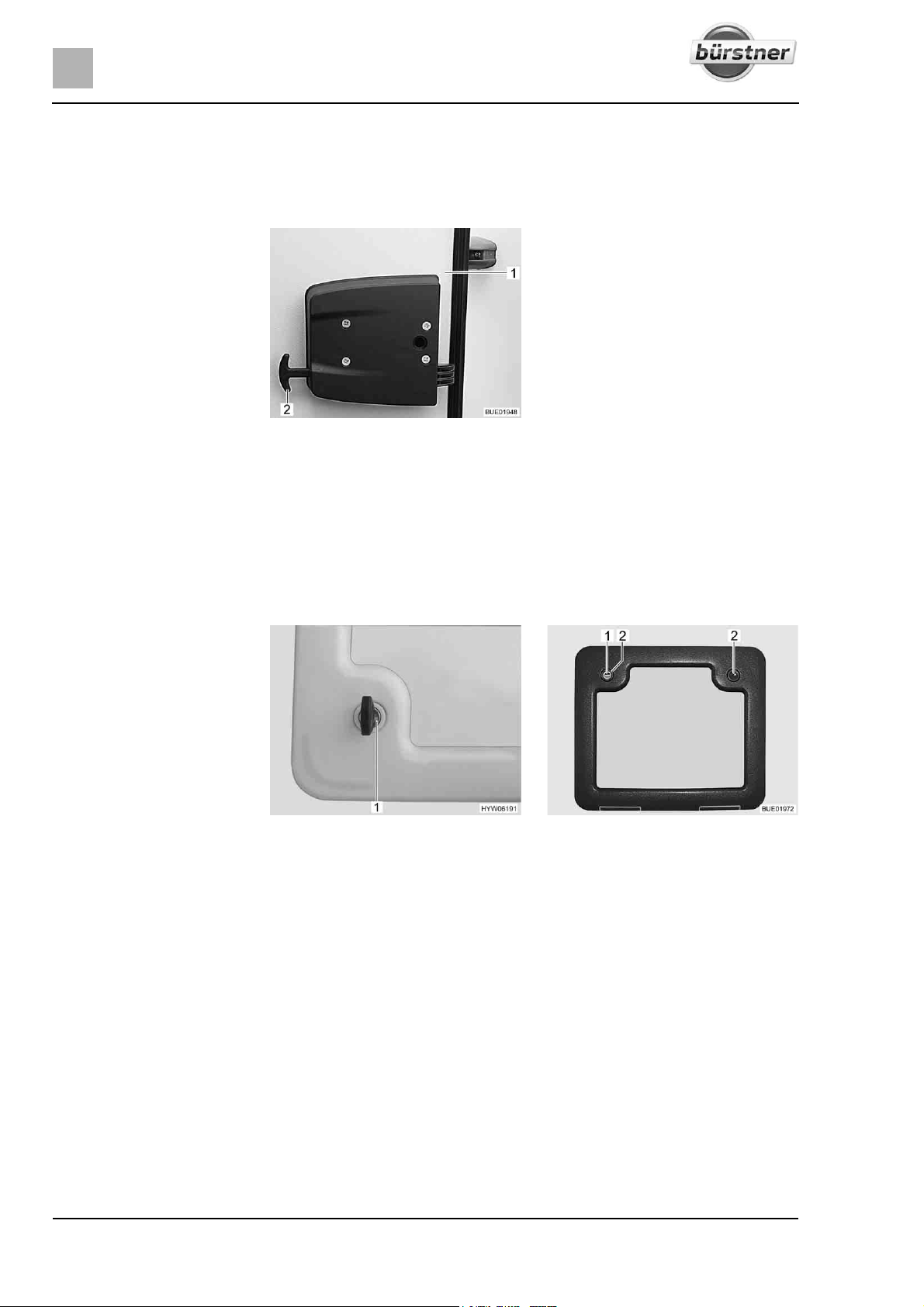
6
Living
6.3.2 Garage flap emergency release
The garage flap can be opened from the interior using the emergency release.
The emergency release is even possible if the garage flap has been locked
with the key.
Unlocking the garage flap:
6.3.3 Flap lock with push button
Opening:
Fig. 50 Garage flap emergency
release
Pull both handles of the emergency release (Fig. 50,2).
Push the garage flap (Fig. 50,1) outwards.
Depending on the flap size the service flap is equipped with one or two lockable push-button locks.
Fig. 51 Service flap push-button lock Fig. 52 Service flap push-button lock
(alternative)
Insert the key into locking cylinder of the lockable push-button lock
(Fig. 51,1 or Fig. 52,1) and turn a quarter turn. The push-button lock is
unlatched.
Remove the key.
If equipped, unlock the second lockable push-button lock as well.
Press the two push buttons (Fig. 52,2) of the push-button locks simultane-
ously with the thumb and open the service flap.
Closing:
62 T-Modell - 17/18 - Ausgabe 09/17 - 2891569 - BUE-0029-19EN
Close the service flap and press it shut. The push-button locks are now
engaged but not locked.
Insert the key into locking cylinder of the lockable push-button lock
(Fig. 51,1 or Fig. 52,1) and turn a quarter turn. The push-button lock is
locked.
Remove the key.
If equipped, lock the second lockable push-button lock as well.
Page 63
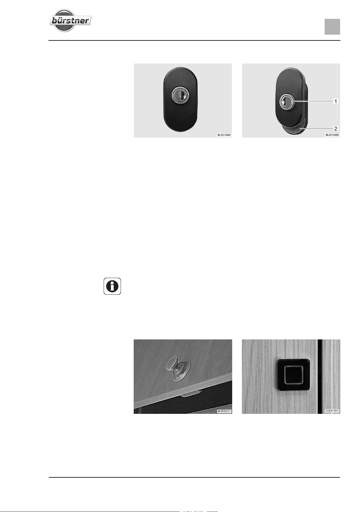
Living
6
6.3.4 Service unit flap lock
Fig. 53 Flap lock, locked Fig. 54 Flap lock, open
Opening: Insert the key into the locking cylinder and turn until the red ring (Fig. 54,1)
is visible. The flap lock is unlatched.
Remove the key.
Turn the handle half a turn in an anticlockwise direction until the red area
(Fig. 54,2) is visible. The lock is open.
Closing:
Close flap.
Turn the handle half a turn in a clockwise direction until the red area
(Fig. 54,2) is no longer visible.
Insert the key into the locking cylinder and turn until the red ring (Fig. 54,1)
is no longer visible.
Remove the key.
6.4 Furniture flaps
Z Before commencing the journey, close all furniture flaps and inner doors
and lock them.
Z The furniture flaps shown in this section are examples. Depending on the
model, the locks and handles on the furniture flaps may differ to those displayed here.
6.4.1 Furniture flaps with push button
Fig. 55 Furniture flap with round push
button
Opening: Press inner part of the lock. The push button (Fig. 55 or Fig. 56) jumps out.
Hold push button and open furniture flap.
Fig. 56 Furniture flap with rectangular
push button
63T-Modell - 17/18 - Ausgabe 09/17 - 2891569 - BUE-0029-19EN
Page 64
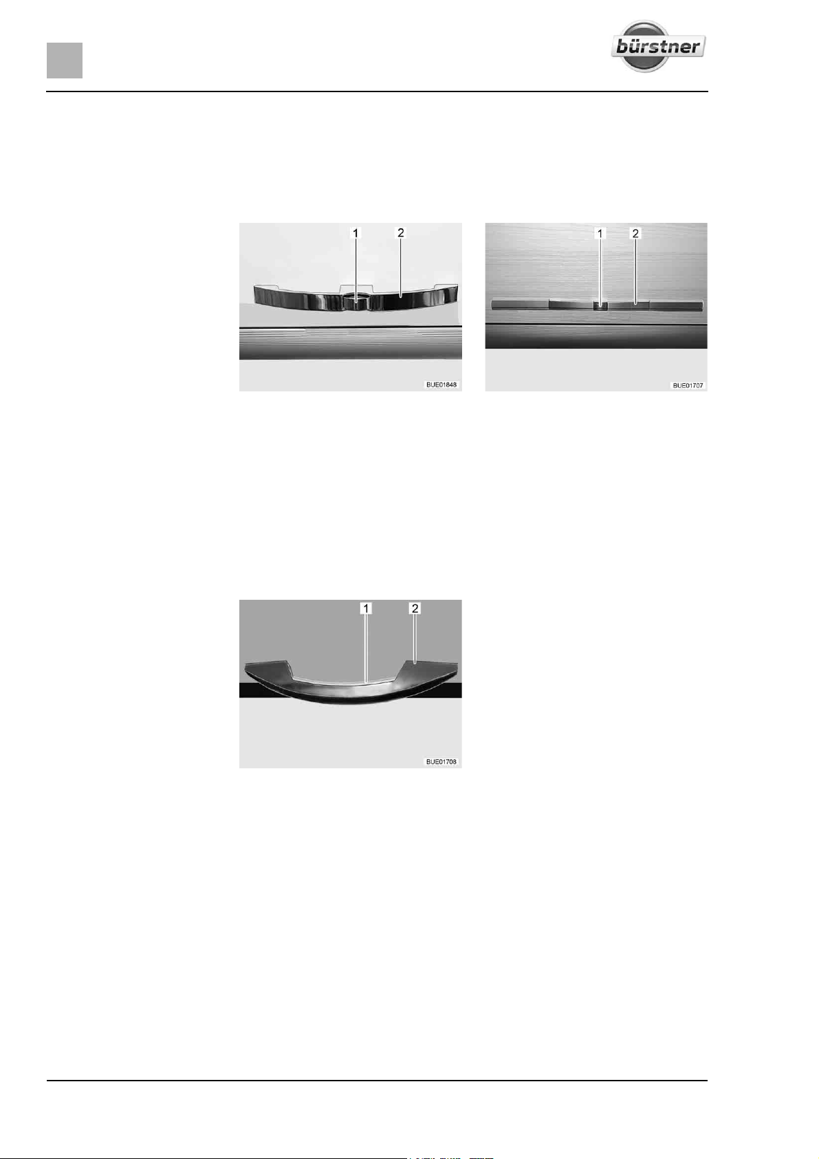
6
Living
Closing: Press furniture flap shut.
Press push button in until it locks. The furniture flap is closed correctly
when the fastener locks into place.
6.4.2 Furniture flaps with handle and push button
Fig. 57 Furniture flap with handle
Opening: Press the release knob (Fig. 57,1 or Fig. 58,1) on the handle (Fig. 57,2 or
Pull handle until furniture flap is open.
Closing:
Press the furniture flap down until you can feel the flap hinge close and
(example)
Fig. 58,2) and hold it down.
hear the lock snap into place.
Fig. 58 Furniture flap with handle
(alternative)
6.4.3 Furniture flaps with handle and unlocking bar
Fig. 59 Handle with unlocking bar
(example)
Opening: Press the unlocking bar (Fig. 59,1) and hold it down.
Pull the handle (Fig. 59,2) until the furniture flap is open.
Closing:
64 T-Modell - 17/18 - Ausgabe 09/17 - 2891569 - BUE-0029-19EN
Press the furniture flap down until you can feel the flap hinge close and
hear the lock snap into place.
Page 65
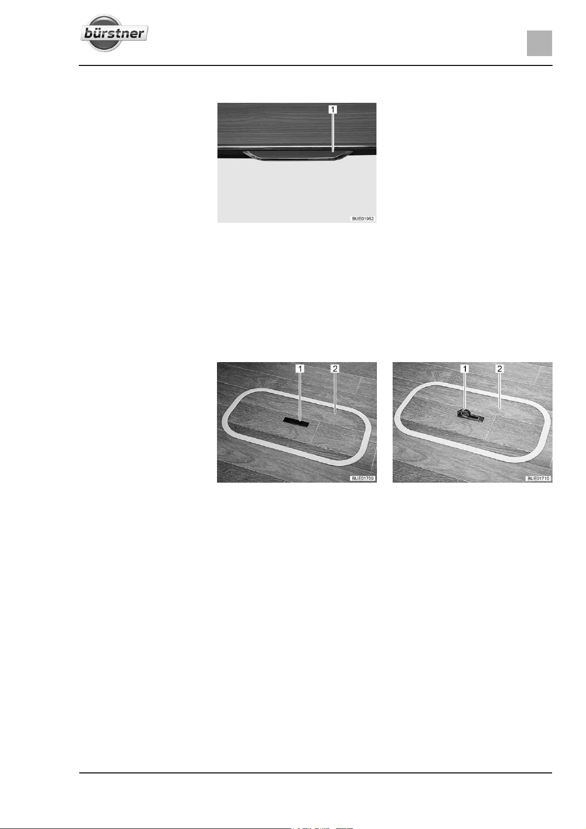
6.4.4 Furniture flaps with release handle
Living
6
Fig. 60 Furniture flap with release
Opening: Pull the release handle (Fig. 60,1) outwards.
Pull the release handle until the furniture flap is open.
Closing:
Press the furniture flap down until you can feel the flap hinge close and
handle
hear the lock snap into place.
6.5 Floor compartment cover
Fig. 61 Floor compartment cover
(handle recessed)
Fig. 62 Floor compartment cover
(handle swung out)
Opening: Push one side of the grip plate (Fig. 61,1) downwards. The handle
(Fig. 62,1) swivels upwards.
Remove the cover (Fig. 61,2 or Fig. 62,2) upwards.
Closing:
Insert the cover in the frame on the floor.
Swivel handle downwards.
65T-Modell - 17/18 - Ausgabe 09/17 - 2891569 - BUE-0029-19EN
Page 66
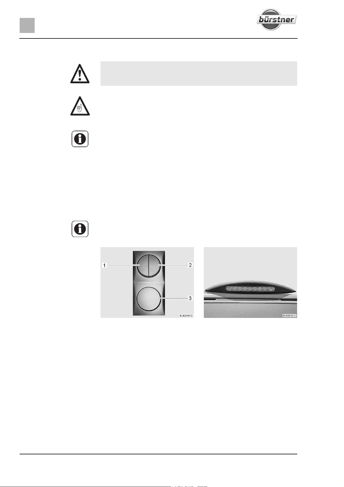
6
Living
6.6 Rotating seats
X Before commencing the journey, rotate all swivel seats in the direction
of travel and lock in position. During the journey, the swivel seats must
remain locked in place in the direction of travel.
Z Push the driver's seat into the central position before rotating it. If the
driver's seat is in the very back or in the very front, there is a risk of colliding
with the handbrake lever or the seating group when rotating the driver's
seat.
Z The driver's seat and the front passenger's seat are part of the base
vehicle. The adjustment of the seats is described in the instruction manual
of the base vehicle.
Rotating: Push both armrests at the driver's/front passenger's seat upward.
Push the driver's seat / front passenger's seat into the central position.
The seats can only be locked in position in the direction of travel.
6.7 Light switch
6.7.1 Entrance area
Z The light switches shown in this section are examples. Depending on the
model, the type and allocation of the light switches may differ to those displayed here.
Fig. 63 Light switch Fig. 64 Awning light
The entrance area has light switches (Fig. 63,1-3) for the following lamps:
z Entrance lights
z Awning lights
z Living area lights
z Canvas blind lighting (special equipment)
66 T-Modell - 17/18 - Ausgabe 09/17 - 2891569 - BUE-0029-19EN
Page 67
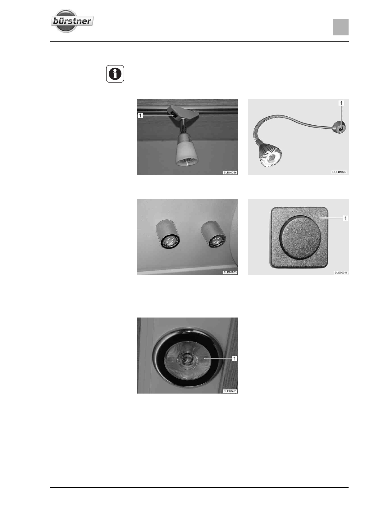
6.7.2 Interior
Z The lamps shown in this section are examples. Not all lamps used in the
vehicle are shown. The examples are intended to clarify the possible positions for the light switches. The type and appearance of the light switches
can deviate from those shown here.
Living
6
Fig. 65 Spotlight, switch mounted
directly on the lamp (example)
Fig. 67 Ceiling lamp, separate from
the switch (example)
The light switches in the interior are located either on the lamp itself (Fig. 65,1
or Fig. 66,1) or near the lamp (Fig. 68,1).
Fig. 66 Spotlight, switch mounted
directly on the lamp (example)
Fig. 68 Switch, separate from the lamp
(example)
Fig. 69 Recessed light, light switch in
To switch the recessed light on and off, press the interior of the recessed light
(Fig. 69,1).
the lamp
67T-Modell - 17/18 - Ausgabe 09/17 - 2891569 - BUE-0029-19EN
Page 68
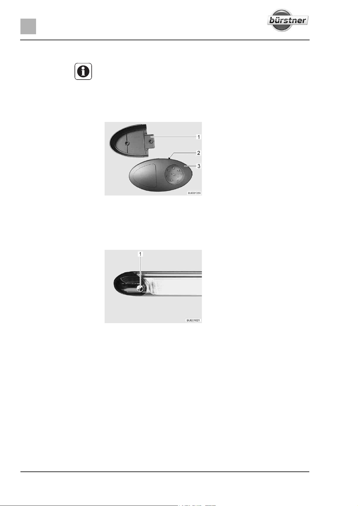
6
Living
6.7.3 Wardrobe light (partially special equipment)
Z The wardrobe light can be removed from its holder (Fig. 70,1) and used as
a torch.
Z When the wardrobe door is closed, the wardrobe light switches off auto-
matically.
Z A brightness sensor ensures that the wardrobe light comes on only when
it is dark. This prevents the wardrobe light from being accidentally switched
on during daylight hours, which would waste the batteries.
Fig. 70 Wardrobe light
The On/Off switch (Fig. 70,2) is located directly on the wardrobe light
(Fig. 70,3).
6.7.4 Tube lamp in the rear garage
Fig. 71 Tube lamp in the rear garage
Move your hand over the sensor (Fig. 71,1) on the lamp to switch it on and off.
68 T-Modell - 17/18 - Ausgabe 09/17 - 2891569 - BUE-0029-19EN
Page 69
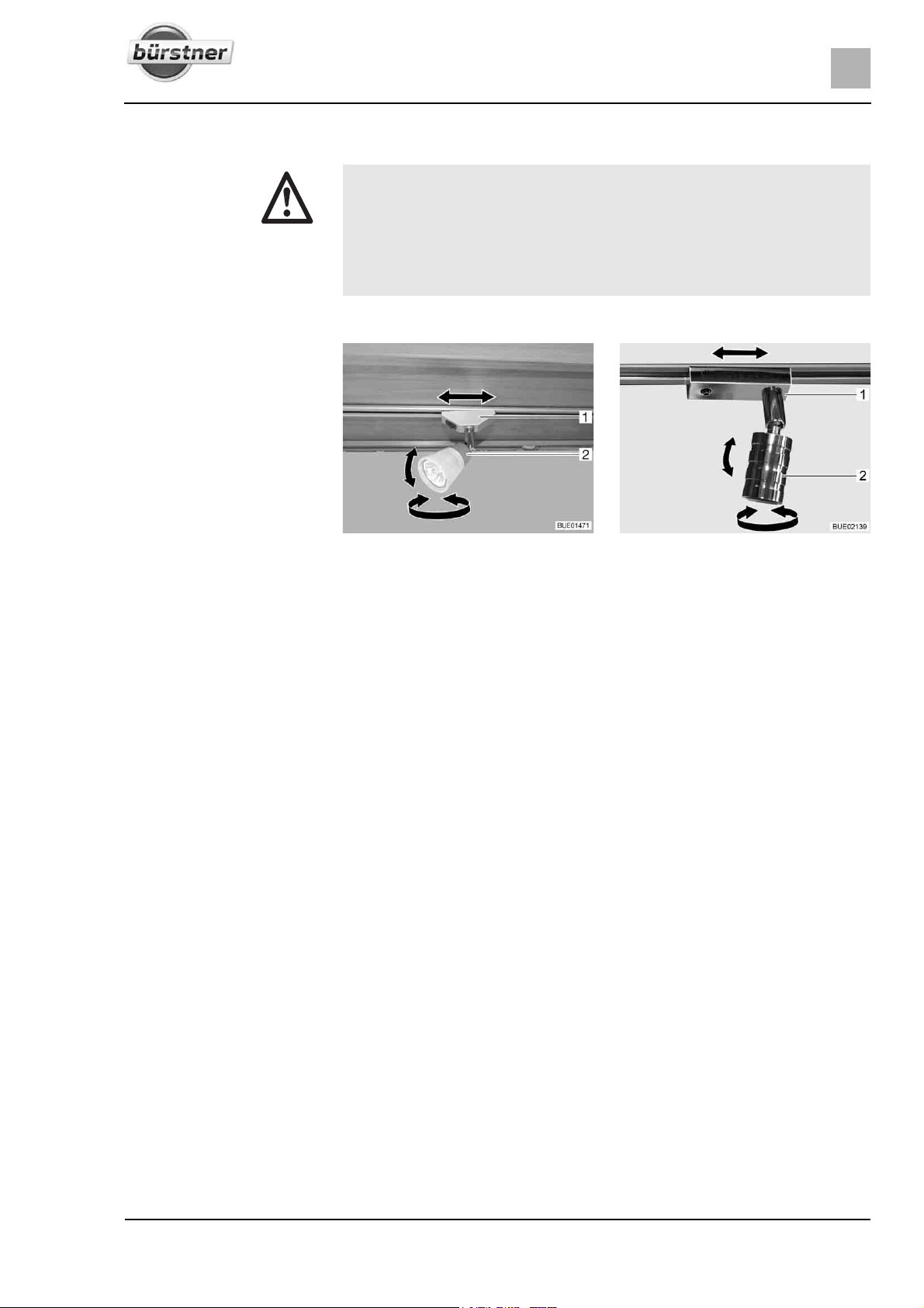
6.8 Spotlight
X Bulbs and light fittings can be extremely hot.
X Allow the light bulbs and lamp holders to cool down before touching
them.
X If the light is switched on or still hot, there must always be a safety dis-
tance of at least 30 cm between stores or curtains and flammable
objects. Fire hazard!
The spotlight can be rotated, moved or detached.
Living
6
Rotating:
Shifting:
Removing:
Fig. 72 Spotlight Fig. 73 Spotlight (alternative)
Grasp the housing (Fig. 72,2 or Fig. 73,2) and turn it.
The housing can be turned in different directions:
z To the left and to the right
z Up and down
Grip socket (Fig. 72,1 or Fig. 73,1) and turn by approx. 45°.
Push spotlight along the rail system to desired position.
Turn socket back.
Grip socket (Fig. 72,1 or Fig. 73,1) and turn by 90°.
Remove spotlight from rail.
The spotlight can be installed in any position into the rails.
69T-Modell - 17/18 - Ausgabe 09/17 - 2891569 - BUE-0029-19EN
Page 70
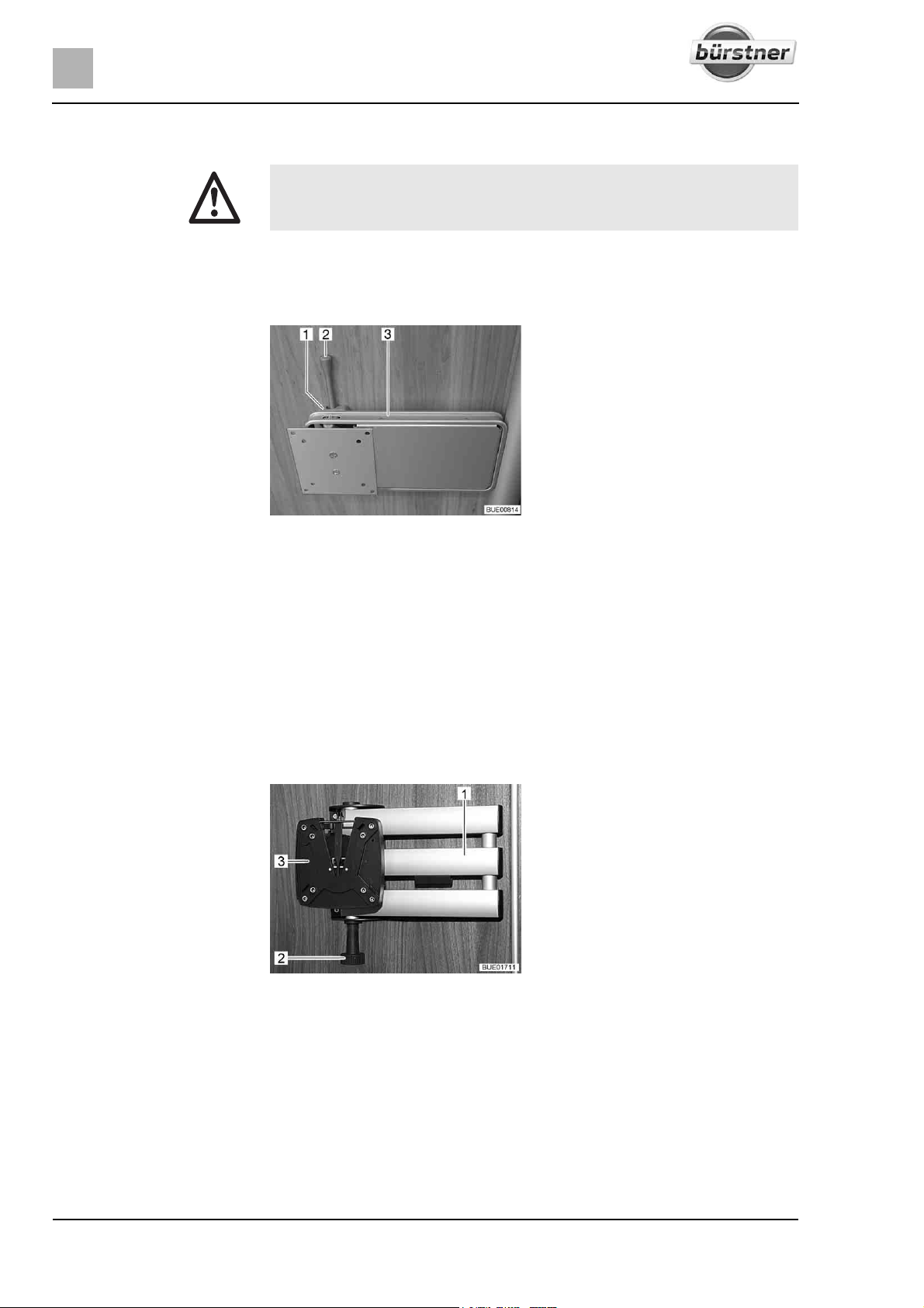
6
Living
6.9 Holder for flat screen
X Before commencing the journey, place and secure the flat screen and
screen support in the initial position. If the screen holder is installed in a
TV cabinet: Close TV cabinet.
6.9.1 Holder on the column
The holder for the flat screen is attached to a column.
Positioning:
Storing away:
6.9.2 Holder with jointed arm
Fig. 74 Holder on the column
Push the release lever (Fig. 74,2) to the side and turn the holder (Fig. 74,3)
with the flat screen to the desired position.
Press the flat screen slightly upwards and swivel it to the desired position.
Three different inclination angles may be used.
Turn the flat screen back until the holder (Fig. 74,3) engages in the lock
(Fig. 74,1).
The flat screen is fastened to a jointed arm.
Fig. 75 Holder with jointed arm
Positioning:
Storing away:
70 T-Modell - 17/18 - Ausgabe 09/17 - 2891569 - BUE-0029-19EN
Pull the release knob (Fig. 75,2). The jointed arm (Fig. 75,1) is unlocked.
Swivel flat screen into the desired position.
Take hold of the flat screen at the top and bottom edge with both hands and
set the desired angle of inclination.
Turn the flat screen back into the original position until you hear the holder
(Fig. 75,3) engage in the lock.
Page 71
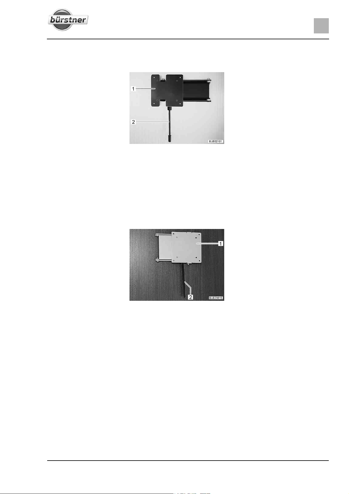
6.9.3 Wall holder
The flat screen is fastened to a wall holder.
Fig. 76 Wall holder
Living
6
Positioning:
Storing away:
6.9.4 Holder with release lever
Positioning:
Pull down the release lever (Fig. 76,1) and turn the holder (Fig. 76,2) with
the flat screen to the desired position.
Pull down the release lever and push back the flat screen until the holder
engages.
The holder for the flat screen is attached to the wall.
Fig. 77 Holder with release lever
Push the release lever (Fig. 77,2) to the side and turn the holder (Fig. 77,1)
with the flat screen to the desired position.
Press the flat screen slightly upwards and swivel it to the desired position.
Three different inclination angles may be used.
Storing away:
Turn flat screen back until the holder (Fig. 77,1) engages in the lock.
71T-Modell - 17/18 - Ausgabe 09/17 - 2891569 - BUE-0029-19EN
Page 72
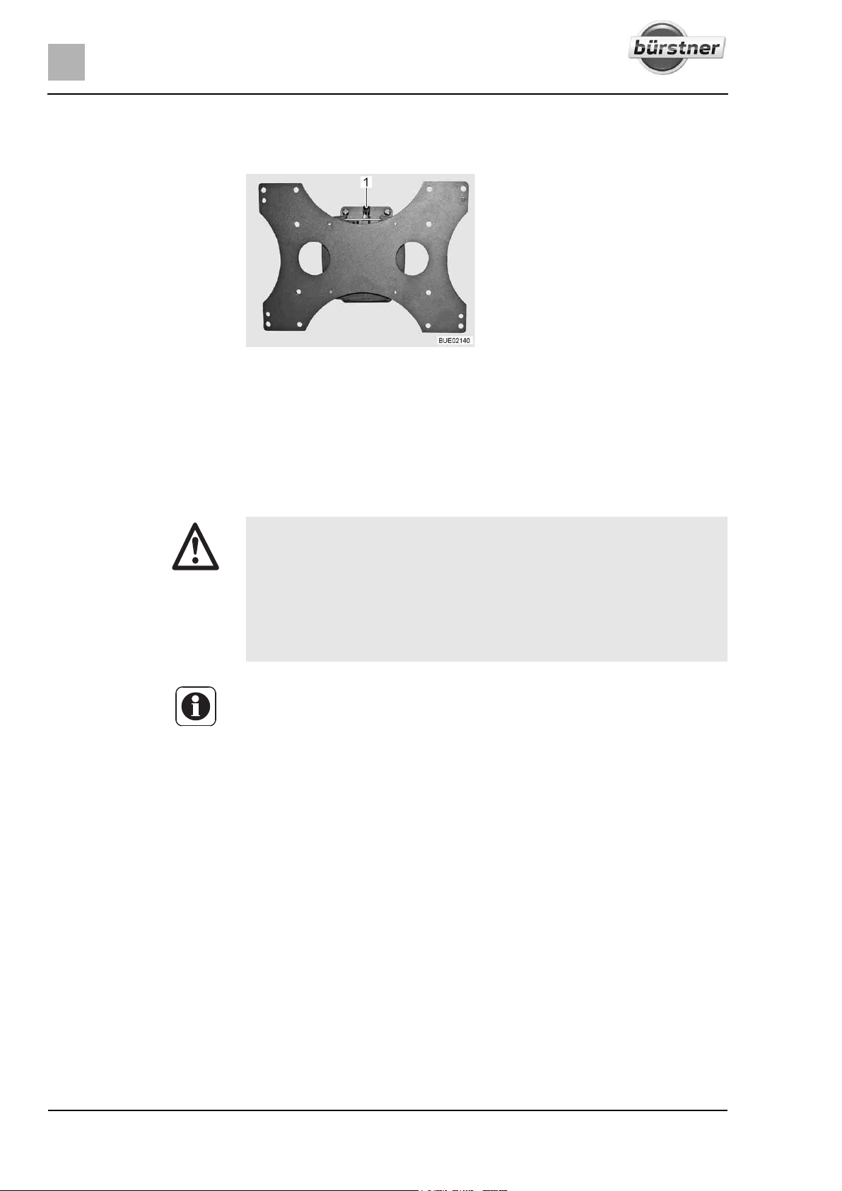
6
Living
6.9.5 Holder, rotatable
The flat screen is fastened to a holder with a rotatable joint.
Fig. 78 Holder (rotatable)
Positioning:
Removing flat screen:
6.10 Ventilation
Condensation Ensure that there is a continuous exchange of air by providing frequent and
Swivel the flat screen into the desired position.
Press and hold latch (Fig. 78,1) to the right.
Remove flat screen upwards.
X The oxygen in the vehicle interior is used up by breathing and the use of
gas operated appliances. That is why the used air must be replaced permanently. For this purpose, forced ventilation options (e.g. skylights with
forced ventilation, mushroom-shaped vents or floor vents) are fitted to
the vehicle. Never cover or block forced ventilations from the inside or
outside with objects such as e.g. a winter mat. Keep forced ventilations
clear of snow and leaves. There is a danger of suffocation due to
increased CO
Z Although sufficient ventilation is provided, in certain weather conditions,
condensation can form on metal objects (e.g. screwed connections in the
floor).
Z Additional cold spots can occur at thermal "bridges" (e.g. mushroom-
shaped vents, skylight edges, sockets, filler necks, flaps, etc.).
efficient ventilation. This is the only method for ensuring that condensation and
resulting mould is not formed during cool weather. During the colder season,
a pleasant living climate is created if heating output, air distribution and ventilation are synchronised. To avoid draft close the air outlet nozzles on the dashboard and set the air distribution of the base vehicle to air circulation.
If the vehicle is laid up for a longer period, occasionally ventilate it well, especially in summer as heat accumulation can occur. Do not only air the interior,
but also the storage spaces which are accessible from the outside. Air the
parking place as well if the vehicle is parked in a closed space (e.g. garage).
The occurrence of condensation could lead to the formation of mould.
levels.
2
72 T-Modell - 17/18 - Ausgabe 09/17 - 2891569 - BUE-0029-19EN
Page 73
6.11 Windows
Z The windows are fitted with a blind or Roman shade and with an insect
screen or folding insect screen. After the latch has been released, the blind
and insect screen automatically spring back to the initial position by tensile
force. In order not to damage the tension mechanics, hold onto the blind or
insect screen and allow it to slowly return to the initial position. The Roman
shade and folding insect screen are made of thin woven fabric. In order not
to damage the Roman shade or the insect screen, grasp the respective
handle and carefully return it to the initial position.
Z Do not keep blinds closed over a longer period of time as that can cause
increased material wear.
Z If the blind or the Roman shade is completely closed, exposure to direct
sunlight can cause heat to accumulate between the blind/the Roman shade
and the window. The window could be damaged.
Therefore, if the shade is installed in the bottom blind box, close the shade
only 2/3 when sunlight is intense. This allows the heat to escape between
the window and the shade.
If the shade is installed in the top blind box, close the shade fully and open
it regularly.
Also move the window into the "continuous ventilation" position.
Z Before commencing the journey, close the windows.
Z Depending on the weather, close the windows far enough to prevent mois-
ture from entering.
Z To open and close the window, open or close all catch levers which are
fitted to the window.
Living
6
Z When leaving the vehicle, always close the windows.
Z In extreme weather conditions or if the temperature fluctuates strongly, a
light condensation film can form on the double-glazed acrylic glass. The
glass is designed in such a way that condensation can evaporate when the
external temperature increases. There is no danger of the double-glazed
acrylic glass being damaged by condensation.
73T-Modell - 17/18 - Ausgabe 09/17 - 2891569 - BUE-0029-19EN
Page 74
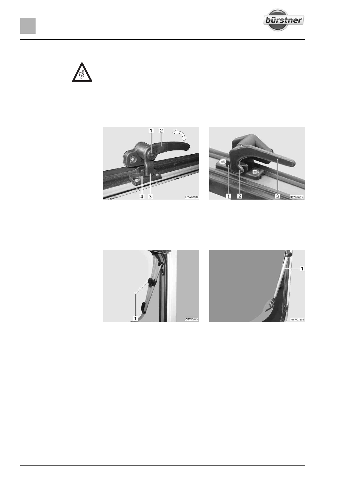
6
Living
6.11.1 Hinged window
Z If windows with automatic hinges are fitted, open the window fully in order
to release the lock. If the locking device is not released and the window is
closed nevertheless, there is the danger of the window breaking due to the
massive counter-pressure.
Z When opening the hinged windows, ensure that there are no torsional
forces. Open and close the hinged windows evenly.
Z If the catch lever is equipped with a safety knob, press the safety knob
when operating the catch lever.
Fig. 79 Catch lever with safety knob in
"closed" position
Opening: Press and hold the security button (Fig. 79,1), if present.
Turn the catch lever (Fig. 79,2 or Fig. 80,3) a quarter turn towards the
centre of the window.
Fig. 81 Hinged window with rotary
hinge
Hinged window with rotary hinge: Open the hinged window until the
required position has been reached and use knurled knob (Fig. 81,1) to
secure in position.
Hinged window with automatic hinge: Open the hinged window to the
desired latched position. The automatic hinge (Fig. 82,1) locks in place
automatically.
Fig. 80 Catch lever in "closed" position
Fig. 82 Hinged window with automatic
hinge
The hinged window remains locked in the required position.
74 T-Modell - 17/18 - Ausgabe 09/17 - 2891569 - BUE-0029-19EN
Page 75
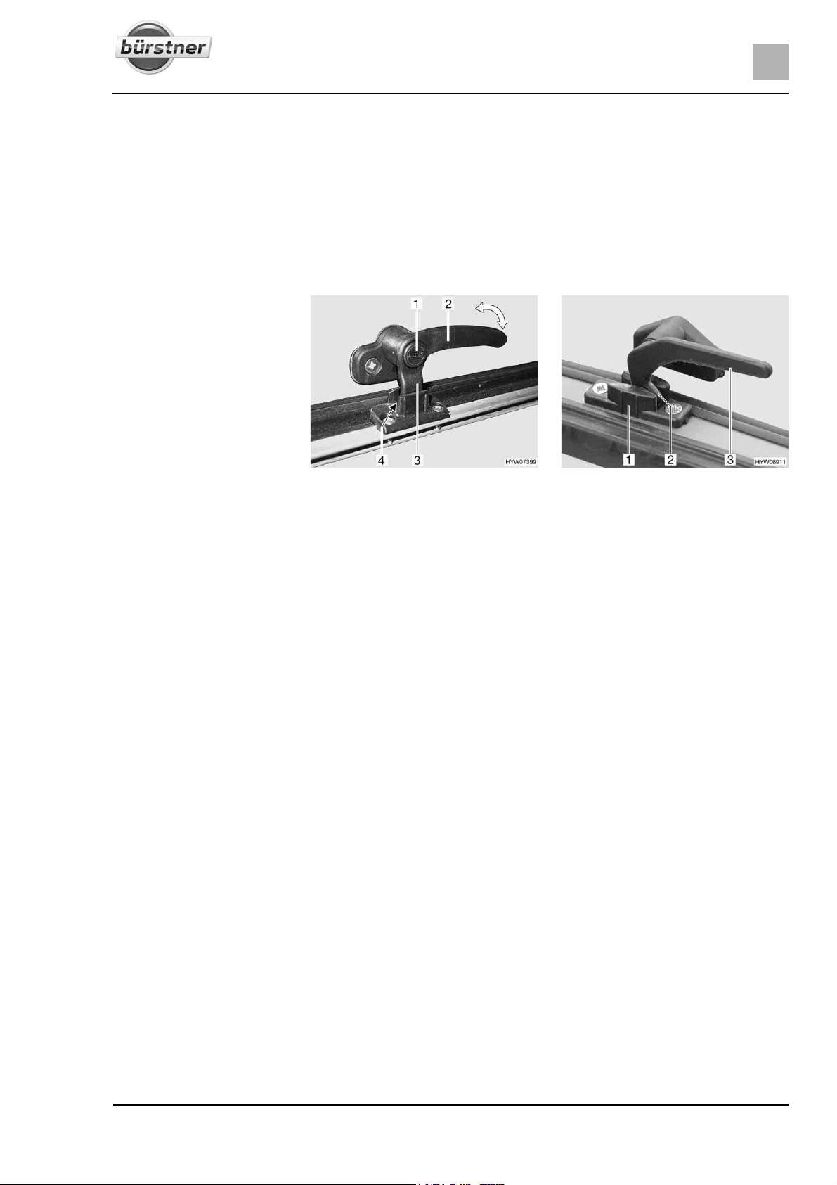
Living
6
Closing: Hinged window with rotary hinge: Turn knurled knob (Fig. 81,1) until the
latch is released.
Hinged window with automatic hinge: Open the hinged window as wide as
is necessary to release the lock.
Close the hinged window.
Press and hold the security button (Fig. 79,1), if present.
Turn the catch lever (Fig. 79,2 or Fig. 80,3) a quarter turn towards the
window frame. The locking catch (Fig. 79,3 or Fig. 80,2) on the catch lever
is entirely on the inner side of the window catch (Fig. 79,4 or Fig. 80,1).
Fig. 83 Catch lever with safety knob in
"continuous ventilation" position
Fig. 84 Catch lever in "continuous ven-
tilation" position
Continuous ventilation With the catch lever, the hinged window can be placed in two positions:
z "Continuous ventilation" (Fig. 83 and Fig. 84)
z "Firmly closed" (Fig. 79 and Fig. 80)
To place the hinged window into the "continuous ventilation" position:
Press and hold the security button (Fig. 83,1), if present.
Turn the catch lever (Fig. 83,2 or Fig. 84,3) a quarter turn towards the
centre of the window.
Slightly open the hinged window outwards.
Return the catch lever to its initial position. Move the locking catch
(Fig. 83,3 or Fig. 84,2) on the catch lever into the recess of the window
catch (Fig. 83,4 or Fig. 84,1).
Press and hold the security button (Fig. 83,1), if present.
Make certain that the safety knob is not pushed in but rather that it secures
the catch lever.
During the journey, the hinged window may not be in "continuous ventilation"
position.
If it rains, the "continuous ventilation" hinged window position could lead to
splashing water penetrating the living area. Therefore, close the hinged windows completely.
75T-Modell - 17/18 - Ausgabe 09/17 - 2891569 - BUE-0029-19EN
Page 76
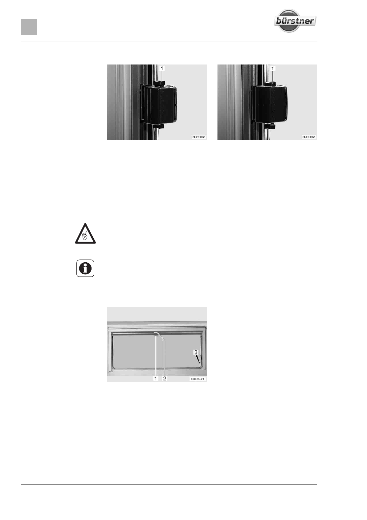
6
Living
6.11.2 Sliding window with pressure lock
Fig. 85 Sliding window, locked Fig. 86 Sliding window, unlocked
Opening: Push the latch (Fig. 85,1) downwards.
Open the window to the desired position.
Closing:
Close the window as far as it can go.
Push the latch (Fig. 86,1) upwards.
6.11.3 Blind and insect screen
Z Open blinds before commencing the journey. When the blinds are closed,
vibrations can damage the spring shaft.
Z Depending on the window size, the blinds are fitted with one or two han-
dles.
The windows are fitted with a blind and an insect screen. The blind and insect
screen are adjusted separately.
Fig. 87 Hinged window
Blind The blind is located in the upper blind box.
Closing:
76 T-Modell - 17/18 - Ausgabe 09/17 - 2891569 - BUE-0029-19EN
Pull blind at the handle (Fig. 87,2) downwards. If the blind is to be com-
pletely closed, it is suspended into the locking devices (Fig. 87,3) situated
on both sides of the window frame.
Page 77
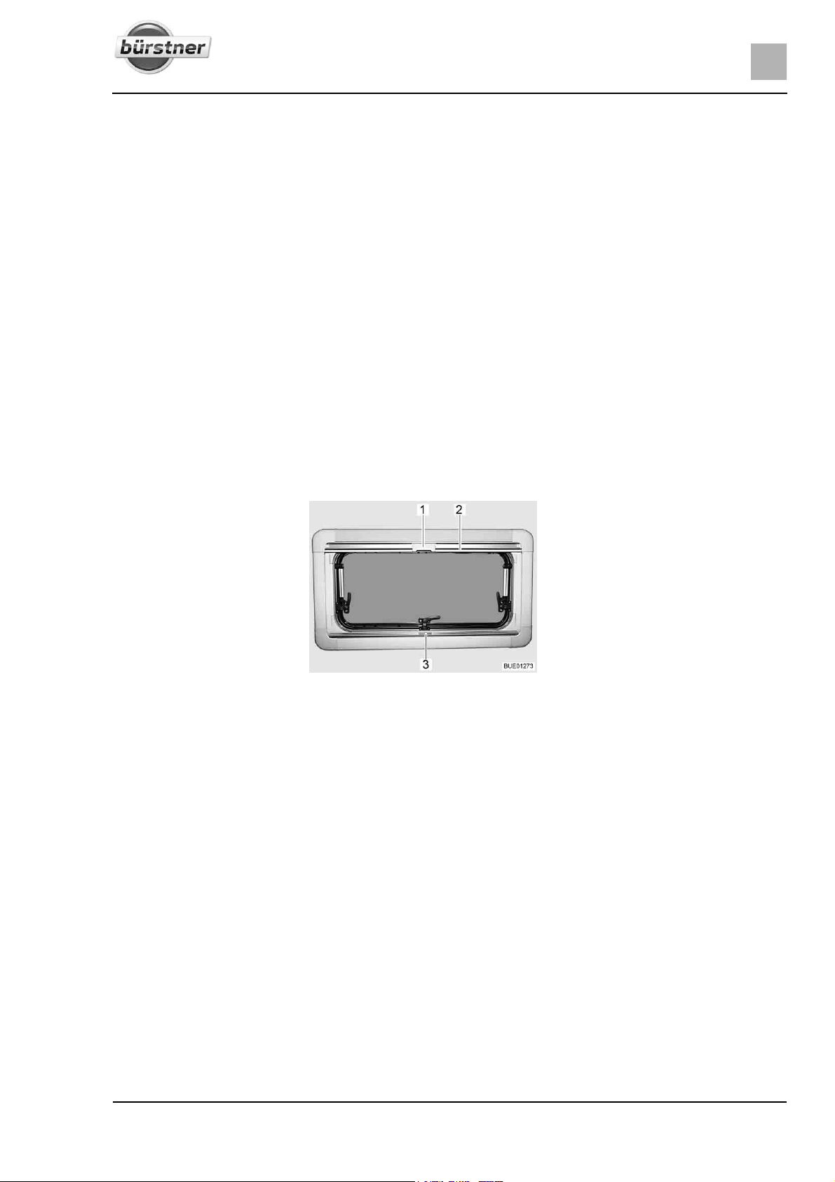
Living
Opening: If the blind is completely closed: Press handle (Fig. 87,2) downwards and,
at the same time, tilt it slightly inward. The blind can be taken out of the
locking devices situated on both sides of the window frame.
If the blind is in an intermediate position: Pull the handle (Fig. 87,2) slightly
downwards until the locking device releases.
Use handle to return blind slowly to its initial position.
Insect screen The insect screen is located in the upper blind box.
6
Closing:
Opening:
Pull insect screen at the handle (Fig. 87,1) down and hang it into the
locking devices (Fig. 87,3) situated on both sides of the window frame.
Press handle (Fig. 87,1) downwards and, at the same time, tilt it slightly
inward. The insect screen can be taken out of the locking devices situated
on both sides of the window frame.
Use handle to return the insect screen slowly to its initial position.
6.11.4 Roman shade and insect screen
The windows are fitted with a Roman shade and an insect screen. The insect
screen can only be moved together with the Roman shade.
Fig. 88 Hinged window
Roman shade The Roman shade is located in the bottom blind box.
Closing:
Opening:
Insect screen The insect screen is located in the upper blind box.
Closing:
Opening:
Grip the Roman shade in the centre of the holding bar (Fig. 88,3), pull it
from the bottom to the top and then release it at the desired height. The
Roman shade will stay at this height.
Grip the Roman shade in the centre of the holding bar and push it down.
Pull the insect screen down using the holding bar (Fig. 88,2), until it
touches the holding bar of the Roman shade (Fig. 88,3).
Clip the catch (Fig. 88,1) on the insect screen into the handle of the Roman
shade.
Push the catch (Fig. 88,1) on the insect screen inwards.
Move the insect screen back slowly on the holding bar (Fig. 88,2).
77T-Modell - 17/18 - Ausgabe 09/17 - 2891569 - BUE-0029-19EN
Page 78
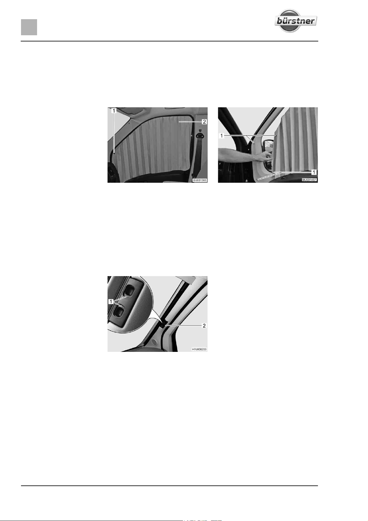
6
Living
6.11.5 Roman shades for windscreen, driver's window and front passenger's window
Depending on the model, the driver's cabin is shaded either with pleated
shades or with Remis Roman shades (special equipment).
Pleated shades The pleated shades are standard equipment on the vehicle.
Remis Roman shades
(special equipment)
Windscreen
Fig. 89 Pleated shades on passenger
window
The pleated shades (Fig. 89,2) are fixed with snap fasteners (Fig. 89,1 and
Fig. 90,1).
The Roman shades are fixed with magnetic strips and are permanently fitted
to the vehicle inside the frame.
Proceed as described below to open or close permanently installed Roman
shades.
Fig. 91 Roman shade for the wind-
screen
Fig. 90 Fixing of pleated shades
Shading:
Opening the Roman shade:
78 T-Modell - 17/18 - Ausgabe 09/17 - 2891569 - BUE-0029-19EN
Press the release handles (Fig. 91,1) and hold them down.
Use the handle (Fig. 91,2) to pull the Roman shade for the windscreen
towards the centre of the window.
Close the second Roman shade for the windscreen in the same way.
A magnetic catch holds both parts of the Roman shade together in the
centre.
Press the release handles (Fig. 91,1) and hold them down.
Use the handle (Fig. 91,2) to pull the two halves of the Roman shade for
the windscreen outwards as far as they will go. As you do so, lift the handle
up as high as the locking recess.
Let go of the release handles (Fig. 91,1) and let them engage.
Page 79
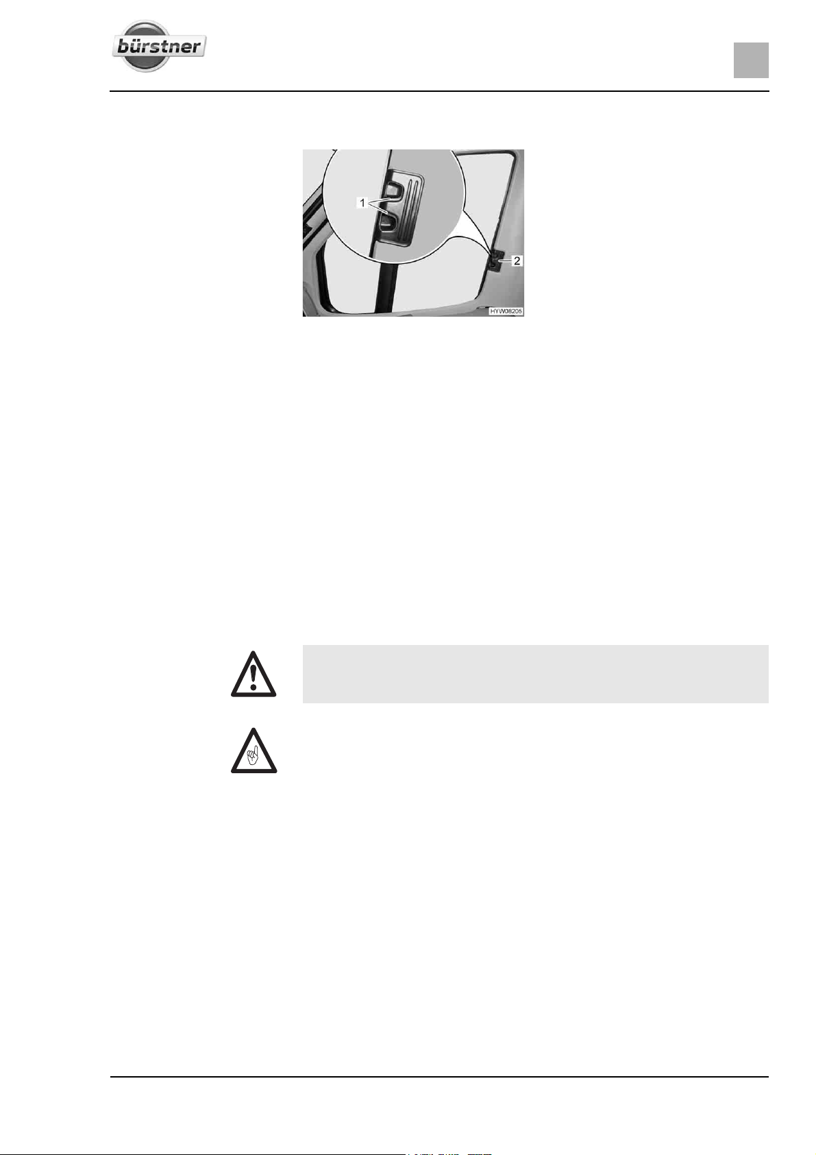
Driver's window and front
passenger's window
Living
6
Shading:
Opening the Roman shade:
6.12 Skylights
Fig. 92 Roman shade for driver's and
passenger's window
Press the release handles (Fig. 92,1) and hold them down.
Using the handle (Fig. 92,2), draw the Roman shades for the driver's and
passenger's window to the other side of the window and secure them to the
magnetic strips.
Press the release handles (Fig. 92,1) and hold them down.
Use handle (Fig. 92,2) to push in the Roman shades for the driver's and
passenger's window as far as possible.
Let go of the release handles (Fig. 92,1) and let them engage.
Depending on the model, skylights with or without forced ventilation are fitted
to the vehicle. If a skylight is fitted without forced ventilation, the forced ventilation is performed using mushroom-shaped vents.
X The apertures for forced ventilation must always be kept open. Never
cover or block forced ventilations with objects such as e.g. a winter mat.
Keep forced ventilations clear of snow and leaves.
Z The skylights are fitted with a blind or Roman shade and with an insect
screen or folding insect screen. After the latch has been released, the blind
and insect screen automatically spring back to the initial position by tensile
force. In order not to damage the tension mechanics, hold onto the blind or
insect screen and allow it to slowly return to the initial position. The Roman
shade and folding insect screen are made of thin woven fabric. In order not
to damage the Roman shade or the insect screen, grasp the respective
handle and carefully return it to the initial position.
Z Do not keep blinds closed over a longer period of time as that can cause
increased material wear.
Z If the blind or the Roman shade is completely closed, exposure to direct
sunlight can cause heat to accumulate between the blind/the Roman shade
and the skylight. The skylight could be damaged. For that reason, close the
blind/Roman shade only 2/3 of the way in direct sunlight. Open the skylight
slightly or move it to ventilation position.
Z Depending on the weather, close the skylights far enough to prevent mois-
ture from entering.
Z Do not climb on the skylights.
79T-Modell - 17/18 - Ausgabe 09/17 - 2891569 - BUE-0029-19EN
Page 80
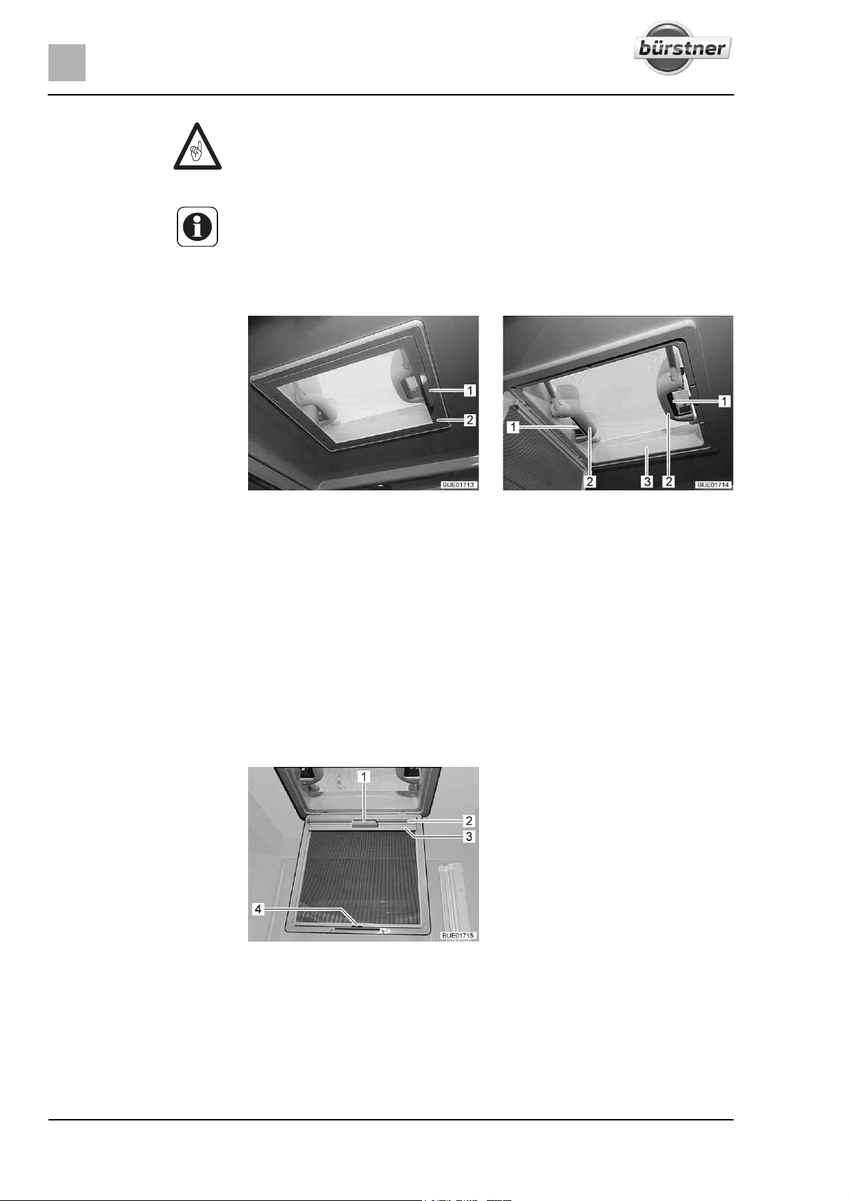
6
Living
Z Before commencing the journey, close the skylights.
Z Before commencing the journey, check that the skylights are closed and
locked.
Z When leaving the vehicle, always close the skylights.
6.12.1 Skylight with snap latch
Opening:
Closing:
Fig. 93 Skylight with snap latch Fig. 94 Handles with snap latches
The skylight can be pushed upwards either from one side or from both sides.
Use handle (Fig. 93,1) to swing down the insect screen (Fig. 93,2).
Push the snap latch (Fig. 94,1) towards the inside of the skylight
(Fig. 94,3). At the same time use the handle (Fig. 94,2) to press the skylight
upwards.
Swing insect screen upwards until it latches in place.
Use handle (Fig. 93,1) to swing down the insect screen (Fig. 93,2).
Using both handles (Fig. 94,2), pull down the skylight (Fig. 94,3) with force
until the two snap latches (Fig. 94,1) lock into place.
Swing insect screen upwards until it latches in place.
Fig. 95 Blind (skylight)
Blind Depending on the equipment, there will be a blind installed.
Closing:
Use handle (Fig. 93,1) to swing down the insect screen (Fig. 93,2).
Using the handle (Fig. 95,1), pull out the blind (Fig. 95,2) and hook the
retainer (Fig. 95,3) into the hook (Fig. 95,4) on the insect screen.
Swing insect screen upwards until it latches in place.
80 T-Modell - 17/18 - Ausgabe 09/17 - 2891569 - BUE-0029-19EN
Page 81
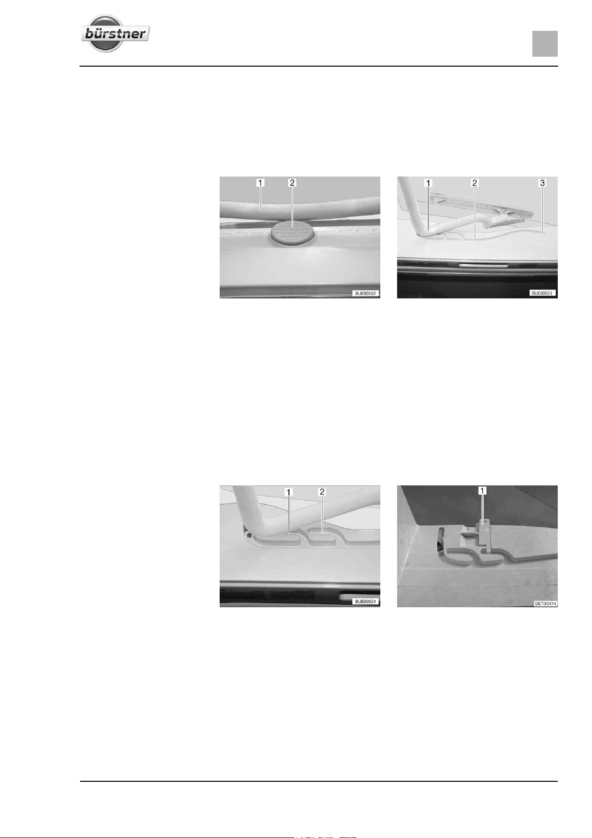
Living
Opening: Use handle (Fig. 93,1) to swing down the insect screen (Fig. 93,2).
Release the retainer (Fig. 95,3) from the hook (Fig. 95,4) and, using the
handle (Fig. 95,1), slowly return the blind (Fig. 95,2).
Swing insect screen upwards until it latches in place.
6.12.2 Heki skylight (mini and midi) (partially special equipment)
6
Opening:
Closing:
Fig. 96 Safety knob on the Heki sky-
light
Fig. 97 Heki skylight, guide
The Heki skylight is opened on one side only.
Press the safety knob (Fig. 96,2) and pull the bar (Fig. 96,1) down with both
hands.
Pull the bar (Fig. 97,1) in the guides (Fig. 97,2) to the rearmost position
(Fig. 97,3).
Use both hands to push the bar (Fig. 97,1) slightly upwards.
Push the bar back in the guides.
Push the bar upwards with both hands until it is above the safety knob
(Fig. 96,2).
Fig. 98 Heki skylight in ventilation
position
Fig. 99 Ventilation position locking
mechanism
Ventilation position The Heki skylight can be put in two ventilation positions: Bad weather position
(Fig. 98,1) and central position (Fig. 98,2). Depending on the model, the skylight can be locked in the central position with both left and right latches
(Fig. 99,1) on the skylight frame.
Press the safety knob (Fig. 96,2) and pull the bar (Fig. 96,1) down with both
hands.
81T-Modell - 17/18 - Ausgabe 09/17 - 2891569 - BUE-0029-19EN
Page 82
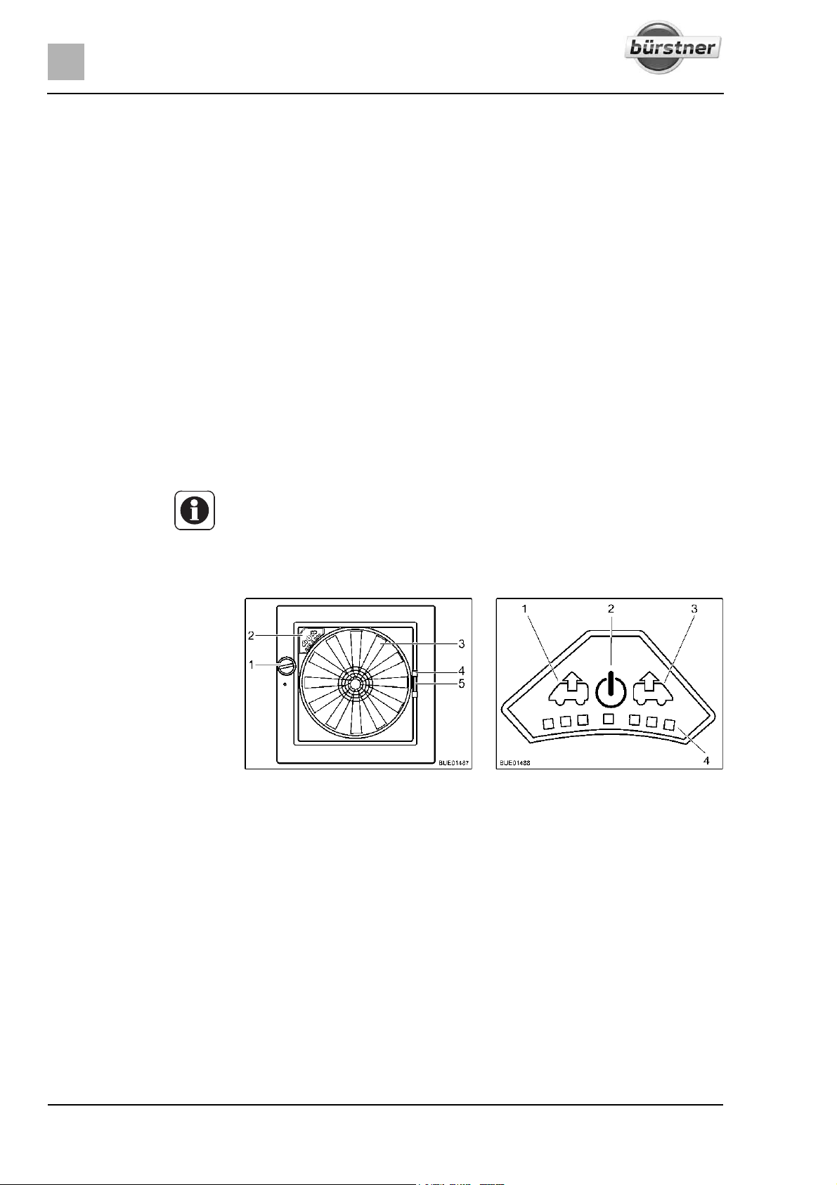
6
Living
Pull the bar in the guides (Fig. 97,2) to the desired position.
Push the bar slightly upwards and into the selected guide (Fig. 98,1 or 2)
and lock if necessary.
Roman shade To close and open the Roman shade:
Closing:
Opening:
Insect screen To close and open the insect screen:
Closing:
Opening:
Pull out Roman shade at the handle and release in the required position.
The Roman shade will stay in that position.
Slowly push the Roman shade at the handle to its initial position.
Pull the insect screen by the handle to the opposite handle of the Roman
shade.
Press the rear part of the handle of the insect screen. The latch is released.
Use handle to return the insect screen slowly to its initial position.
6.12.3 Omni-Vent skylight with fan (special equipment)
Z To save the battery, after one hour the fan automatically switches from
level 6 down to level 1.
The skylight is equipped with an insect screen, blind and an adjustable fan for
ventilation.
Fig. 100 Omni-Vent skylight Fig. 101 Control panel for fan
Opening:
Closing:
82 T-Modell - 17/18 - Ausgabe 09/17 - 2891569 - BUE-0029-19EN
Turn the knob (Fig. 100,1) until the desired opening angle is reached.
Turn the knob (Fig. 100,1) until the skylight is fully closed.
Page 83

Insect screen To close and open the insect screen:
Living
6
Closing:
Using the handle (Fig. 100,4) pull the insect screen across to the other side
of the frame.
Opening:
Press the handle of the insect screen together. The latch is released.
Use handle to return the insect screen slowly to its initial position.
Shade To close and open the shade:
Closing:
Press together the handle (Fig. 100,5) of the shade.
Pull out the shade to the desired position and release. The shade will stay
in that position.
Opening:
Press together the handle of the shade.
Slowly return the shade to its initial position.
Fan If the skylight is open, the interior can be vented and aerated with the 6-speed
fan (Fig. 100,3). The fan is operated via the operating panel (Fig. 100,2).
Switching on:
Press the On/Off button (Fig. 101,2). The fan runs in comfort mode (venting
at slowest fan speed).
Venting:
To increase the fan speed: Press the Vent button (Fig. 101,1). The fan
speed in the venting direction increases by one level. LEDs (Fig. 101,4)
show the operating levels.
To lower the fan speed: Press the Aerate button (Fig. 101,3). The fan
speed decreases by one level.
Aerating:
Boost function:
Switching off:
To increase the fan speed: Press the Aerate button (Fig. 101,3). The fan
speed in the aerating direction increases by one step. LEDs (Fig. 101,4)
show the operating levels.
To lower the fan speed: Press the Vent button (Fig. 101,1). The fan speed
decreases by one level.
Press and hold the Aerate button for approx. 3 seconds. The fan switches
to the maximum aeration level and then, after approximately 5 minutes,
automatically switches back to the previously selected level.
Press and hold the Vent button for approx. 3 seconds. The fan switches to
the maximum venting level and then, after approximately 5 minutes, automatically switches back to the previously selected level.
Press the On/Off button (Fig. 101,2). The fan stops, the LEDs go out.
83T-Modell - 17/18 - Ausgabe 09/17 - 2891569 - BUE-0029-19EN
Page 84
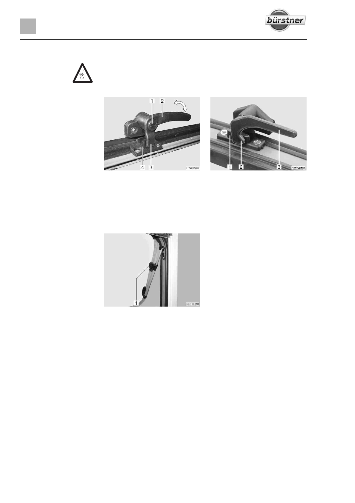
6
Living
6.12.4 Skyroof skylight (partially special equipment)
Z When opening the skylight, ensure that there are no torsional forces. Open
and close the skylight evenly.
Z If the catch lever is equipped with a safety knob, press the safety knob
when operating the catch lever.
Fig. 102 Catch lever with safety knob in
"closed" position
Fig. 103 Catch lever in "closed" position
Opening: Press and hold the security button (Fig. 102,1), if present.
Turn all catch levers (Fig. 102,2 or Fig. 103,3) a quarter turn towards the
centre of the skylight.
Press and hold the security button, if present.
Fig. 104 Skylight with rotary hinges,
Open the skylight until the required position has been reached and use
open
knurled knob (Fig. 104,1) to secure in position.
The skylight remains locked in the desired position.
Closing:
Turn knurled knob (Fig. 104,1) until the latch is released.
Close the skylight.
Press and hold the security button (Fig. 102,1), if present.
Turn all catch levers (Fig. 102,2 or Fig. 103,3) a quarter turn towards the
frame. The locking catch (Fig. 102,3 or Fig. 103,2) is located on the inside
of the skylight lock (Fig. 102,4 or Fig. 103,1).
Press and hold the security button, if present.
84 T-Modell - 17/18 - Ausgabe 09/17 - 2891569 - BUE-0029-19EN
Page 85
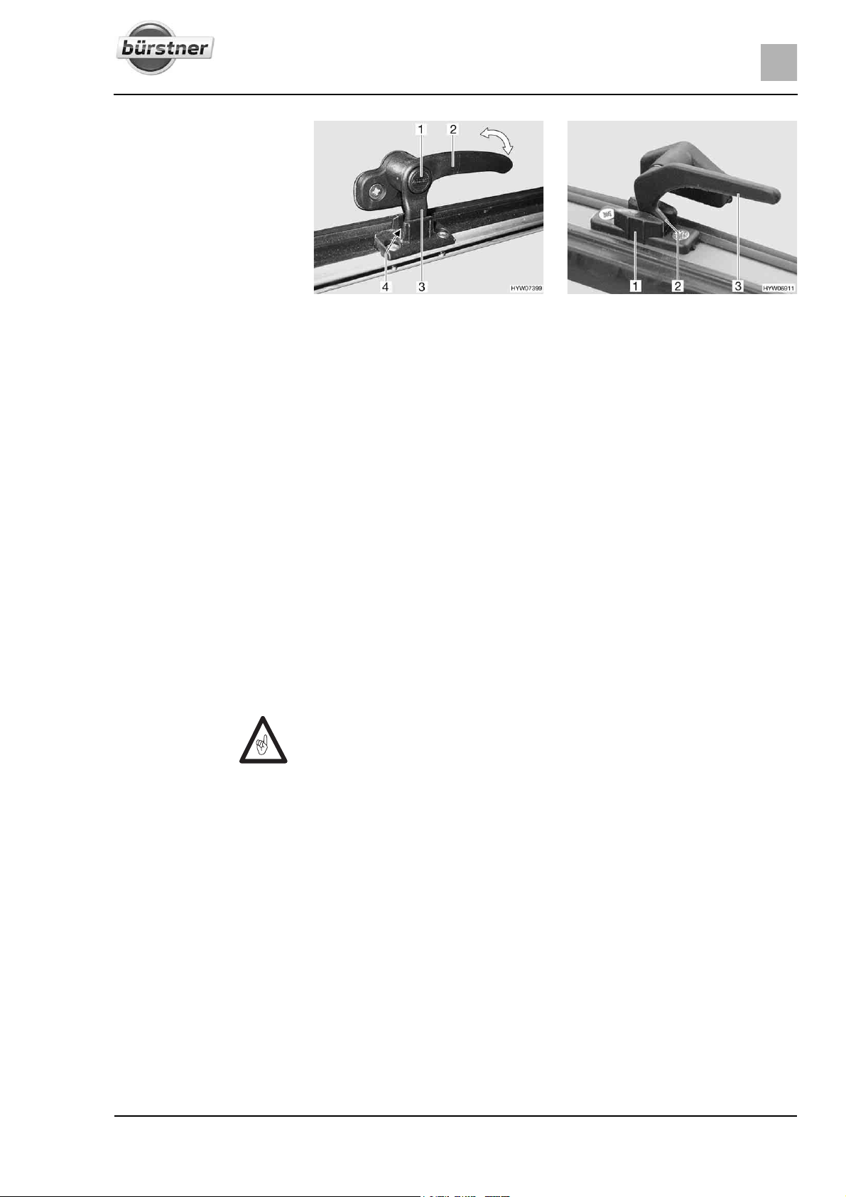
Living
6
Fig. 105 Catch lever with safety knob in
"continuous ventilation" position
Fig. 106 Catch lever in "continuous ven-
tilation" position
Continuous ventilation With the catch levers, the skylight can be placed in 2 different positions:
z "Continuous ventilation" (Fig. 105 and Fig. 106)
z "Firmly closed" (Fig. 102 and Fig. 103)
To place the skylight into the "continuous ventilation" position:
Press and hold the security button (Fig. 105,1), if present.
Turn all catch levers (Fig. 105,2 or Fig. 106,3) a quarter turn towards the
centre of the skylight.
Slightly push the skylight outwards.
Return all catch levers to their initial position. The locking catch (Fig. 105,3
or Fig. 106,2) has to be moved into the recess of the skylight lock
(Fig. 105,4 or Fig. 106,1).
Press and hold the security button, if present.
During the journey, the skylight may not be in the "continuous ventilation" position.
If it rains, the "continuous ventilation" skylight position could lead to splashing
water penetrating the living area. Therefore, close the skylight completely.
Z If the Roman shade is completely closed, heat can accumulate between
the Roman shade and the glass windows when exposed to direct sunlight.
The skylight could be damaged. For that reason, close the Roman shade
only 2/3 of the way in direct sunlight. Open the skylight slightly or move it
to ventilation position.
85T-Modell - 17/18 - Ausgabe 09/17 - 2891569 - BUE-0029-19EN
Page 86
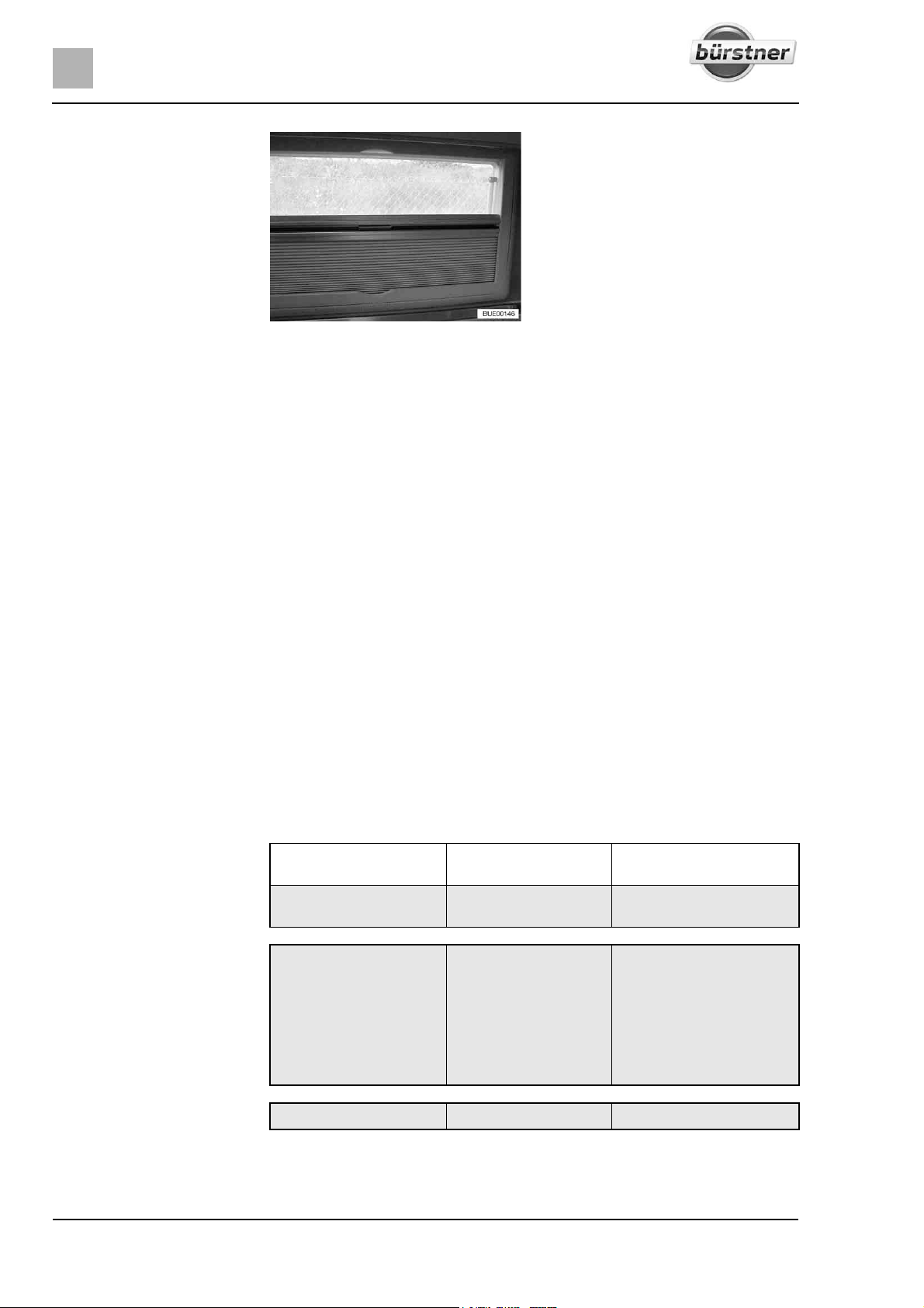
6
Living
Fig. 107 Skyroof skylight
Roman shade The Roman shade is fitted in the frame, at the bottom.
Closing:
Hold the Roman shade in the centre of the bottom rod and carefully draw
it upwards.
Release the Roman shade at the desired position. The Roman shade will
stay in that position.
Opening:
Carefully return the bottom rod of the Roman shade downwards to the limit
stop on the frame.
Insect screen The insect screen is fitted in the frame, at the top.
Closing:
Hold the insect screen in the centre of the bottom rod and carefully pull it
down.
Continuous adjustment of the insect screen may be made by moving the
bottom rod.
Opening:
Carefully return the bottom rod of the insect screen upwards to the limit
stop on the frame.
6.13 Tables
Depending on the model and equipment, various types of tables may be
installed. The tables' features differ in the following ways:
Table leg Table top Conversion to bed foun-
Fixed table
Screwed to the floor Shiftable, rotatable,
partially enlargeable
dation
Not possible
Suspension table
Lift-off table
z Changeable
z Foldable
z Divisible
Lifting mechanism Shiftable, rotatable Lower the table
Extendible Hang the table top from the
top into the bottom mounting rail
z Fold in the table leg
z Change the table leg
z Divide the table leg
86 T-Modell - 17/18 - Ausgabe 09/17 - 2891569 - BUE-0029-19EN
Page 87
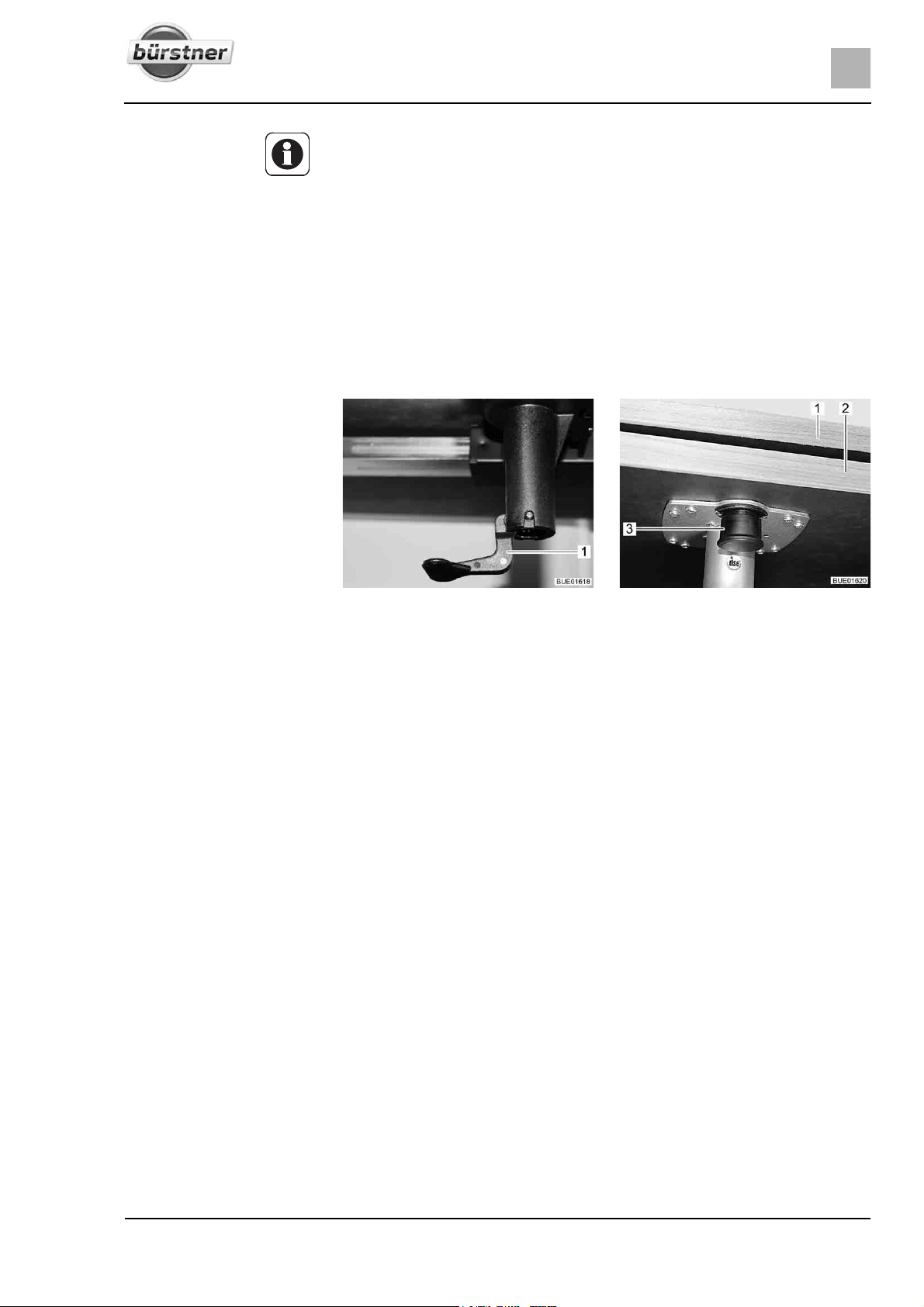
Living
Z Depending on the model, the tables can be adjusted in one or more of the
aforementioned ways.
The tables' main operation is described below. The type and position of the
operating controls may vary slightly.
6.13.1 Fixed table
Table leg The table leg is screwed into the floor.
The fixed table cannot be used as a bed foundation.
Adjusting the table top Depending on the model, the table top can be rotated, moved or extended.
6
Rotating the table top:
Moving the table top:
Expanding the table:
Reducing the table size:
Fig. 108 Unlocking of the table top Fig. 109 Swing-out table extension
Rotate table top to the desired position. In order to do this, you need a little
effort, because the table top rotates against the friction resistance on the
pillar table leg.
Fold lever (Fig. 108,1) downward.
Move the table top to the desired position.
Fold the lever back upwards.
Pull the knob (Fig. 109,3) of the lock down and swing out the table exten-
sion (Fig. 109,2).
Swing the table extension (Fig. 109,2) under the table top (Fig. 109,1) until
the lock latches in place audibly.
87T-Modell - 17/18 - Ausgabe 09/17 - 2891569 - BUE-0029-19EN
Page 88
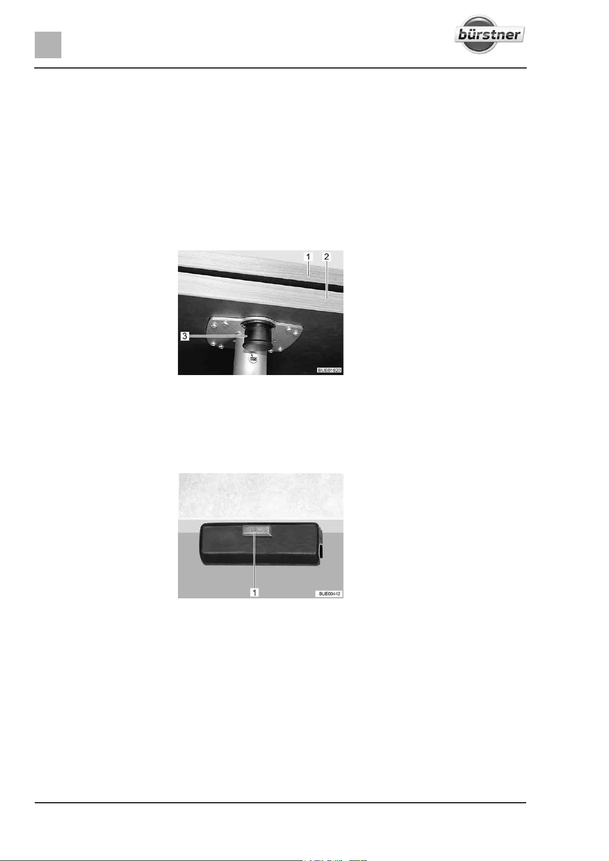
6
Living
6.13.2 Suspension table
Table leg The table leg can be set up at two different heights:
z Normal table height
z Decreased table height (when converting to a bed foundation)
To lower the table, there are the following possibilities (depending on model):
z Replacing the long table leg with a short one
z Folding in one part of the table leg
z Removing one part of the table leg
Table top Depending on the model, the table top can be extended.
Expanding the table:
Reducing the table size:
Conversion to bed
foundation:
Fig. 110 Swing-out table extension
Pull the knob (Fig. 110,3) of the lock down and swing out the table exten-
sion (Fig. 110,2).
Swing the table extension (Fig. 110,2) under the table top (Fig. 110,1) until
the lock latches in place audibly.
Fig. 111 Lock
Lift the front of the table top by approx. 45°.
Depending on the model, shorten the table leg to the conversion level.
Release the lock (Fig. 111,1) on the table top.
Take the table top out of the upper retainer.
Hook the table top at a 45° angle to the supports into the lower retainer and
place on the floor with the shortened table leg.
Lock the table top.
88 T-Modell - 17/18 - Ausgabe 09/17 - 2891569 - BUE-0029-19EN
Page 89
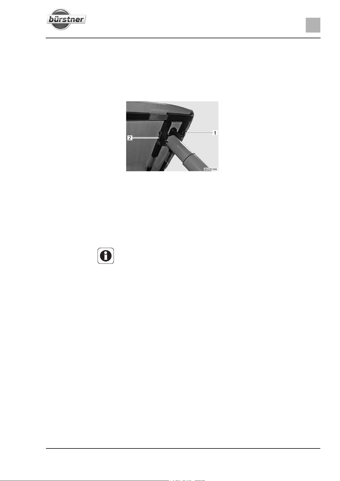
Living
6.13.3 Lift-off table
Table leg The table leg is screwed into the floor. The table can be lowered via a lifting
mechanism to become a bed foundation.
Adjusting the table top Depending on the model, the table top can be moved both lengthwise and
crosswise.
Fig. 112 Adjustment of lift-off table
6
Moving in a lengthways
direction:
Moving in a crossways
direction:
Rotating the table top: Rotate table top to the desired position. In order to do this, you need a little
Conversion to bed
foundation:
Fold lever (Fig. 112,1) downward.
Move the table top to the desired position.
Fold the lever back upwards.
Fold lever (Fig. 112,1) downward.
Move the table top to the desired position.
Fold the lever back upwards.
Z Before lowering the table top, remove the cushions from the benches or
shift the table top (depending on the installation situation).
effort, because the table top rotates against the friction resistance on the
pillar table leg.
Swivel the lever (Fig. 112,2) underneath the table top by 180° in a clock-
wise direction. The lifting mechanism in the table leg is unlocked.
Push the table top downwards as far as possible and hold it in that position.
Press on the centre of the table top.
Swivel back the lever by 180° in an anticlockwise direction. The table top
remains in the lowest position.
Moving the table top
upwards:
Swivel the lever (Fig. 112,2) underneath the table top by 180° in a clock-
wise direction. The table top moves automatically upwards to the limit stop.
Swivel back the lever by 180° in an anticlockwise direction. The table top
remains in the uppermost position.
89T-Modell - 17/18 - Ausgabe 09/17 - 2891569 - BUE-0029-19EN
Page 90
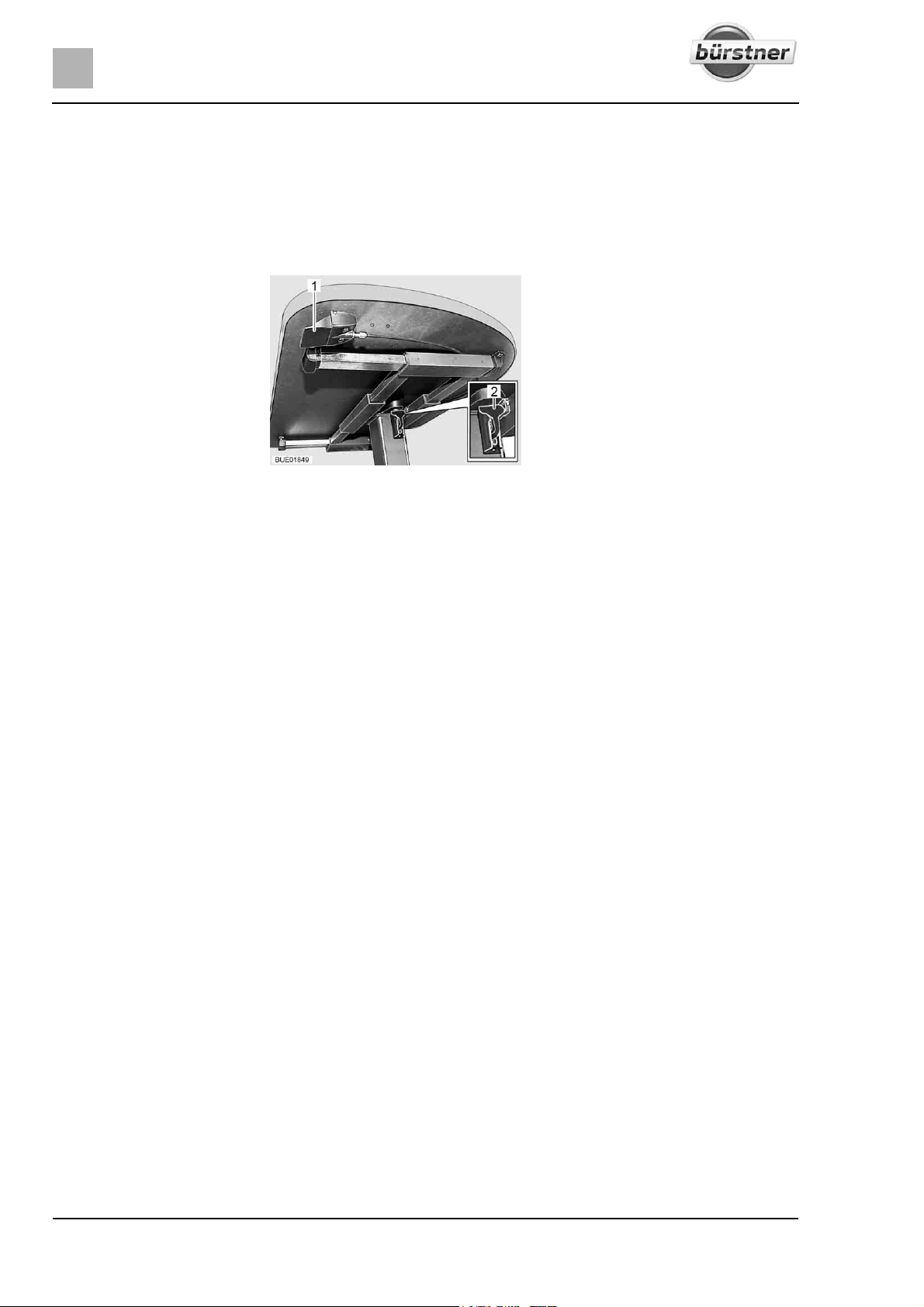
6
Living
6.13.4 Lift-off table (variant)
Table leg The table leg is screwed into the floor. The table can be lowered via a lifting
mechanism to become a bed foundation.
Adjusting the table top Depending on the model, the table top can be rotated and shifted both length-
wise and crosswise.
Fig. 113 Adjustment of lift-off table
Rotating the table top:
Moving the table top:
Conversion to bed
foundation:
Moving the table top
upwards:
Rotate table top to the desired position. In order to do this, you need a little
effort, because the table top rotates against the friction resistance on the
pillar table leg.
Fold down the catch lever (Fig. 113,2).
Move the table top to the desired position.
Fold the catch lever up.
Press up the lever (Fig. 113,1) under the table top. The lifting mechanism
in the table leg is unlocked.
Push the table top downwards as far as possible and hold it in that position.
Press on the centre of the table top.
Release the lever. The table top remains in the lowest position.
Press up the lever (Fig. 113,1) under the table top. The table top moves
automatically upwards to the limit stop.
Release the lever. The table top remains in the uppermost position.
90 T-Modell - 17/18 - Ausgabe 09/17 - 2891569 - BUE-0029-19EN
Page 91
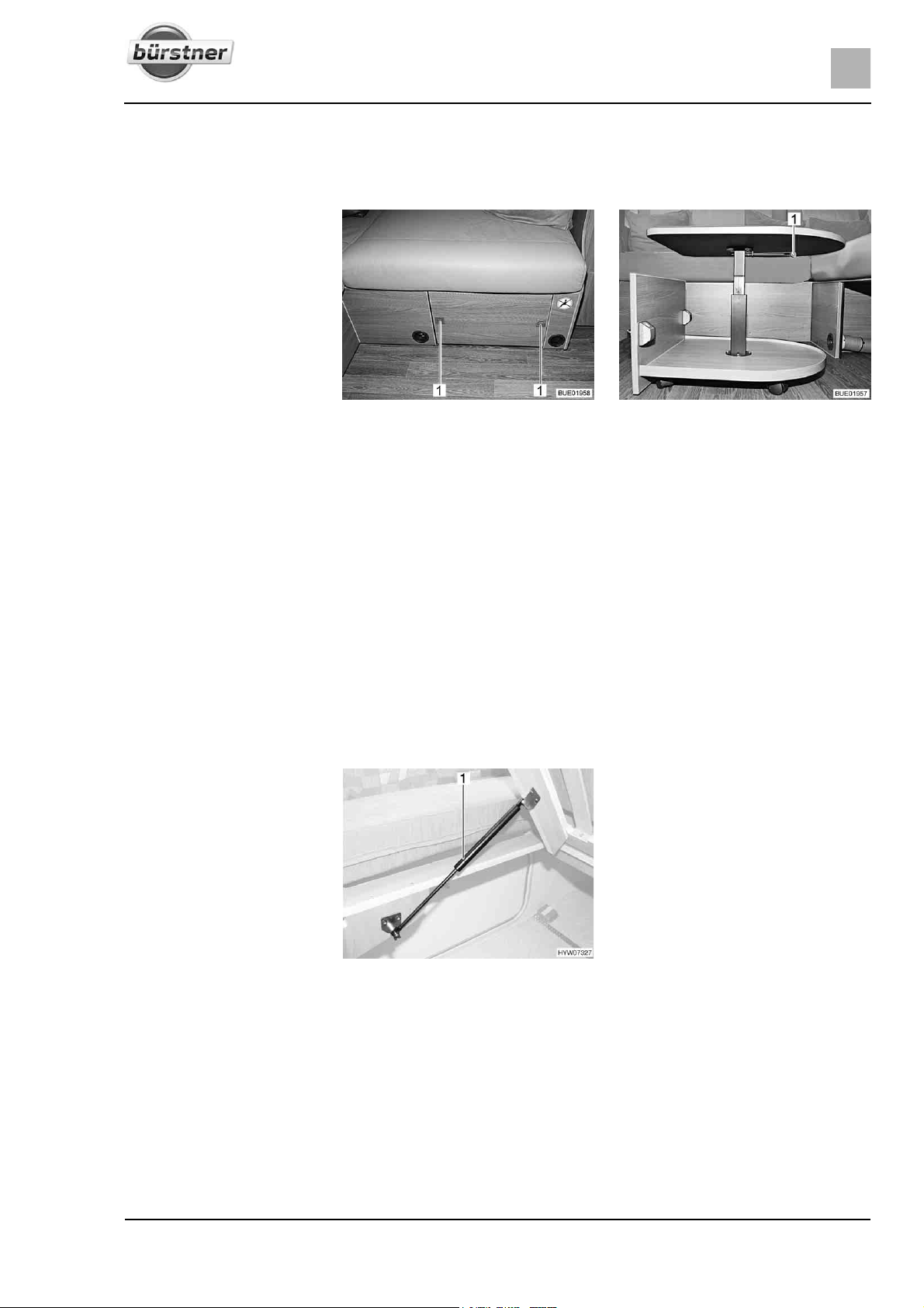
6.13.5 Coffee table (dependent on model)
The coffee table can be lowered. The coffee table can be stored in the seat
box.
Fig. 114 Coffee table, stored Fig. 115 Coffee table, extended
Living
6
Extending the coffee table:
Adjusting the table height:
Storing the coffee table:
6.14 Beds
6.14.1 Fixed bed (gas-pressure springs)
Press the push buttons (Fig. 114,1) on the seat box panel. The push but-
tons jump out.
Pull the coffee table out.
Turn the catch lever (Fig. 115,1) 90° downwards.
Move the table top to the desired position.
Turn the catch lever upwards again.
Turn the catch lever 90° downwards and lower the coffee table.
Run the coffee table into the seat box.
Press the push buttons (Fig. 114,1) in until they engage.
Opening:
Closing:
Fig. 116 Fixed bed
A storage space is underneath the bed. Lift up the slatted frame to place items
in the storage space or to empty it from the inside of the vehicle.
Lift the mattress forwards.
Lift slatted frame. The gas-pressure springs (Fig. 116,1) hold the slatted
frame open.
Press the slatted frame downwards against the resistance of the gas-pres-
sure springs.
91T-Modell - 17/18 - Ausgabe 09/17 - 2891569 - BUE-0029-19EN
Page 92
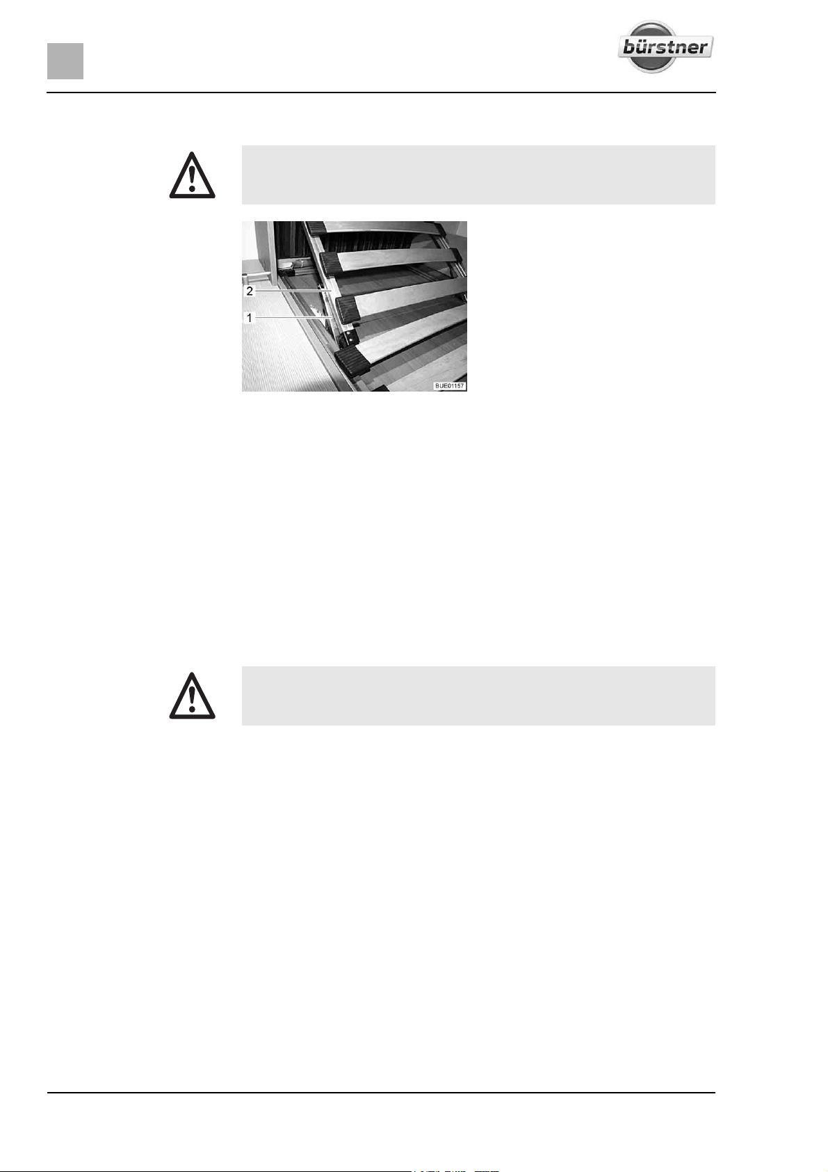
6
Living
6.14.2 Fixed bed (adjustable head section)
X Do not let the slatted frame fall down when closing the bed!
Fig. 117 Adjustable head section
Depending on the configuration, the head section of the slatted frame can be
adjusted in several stages.
Raising the head section:
Lowering the head section:
6.14.3 Fixed bed, hydraulic height adjustable (special equipment)
Raise the head section (Fig. 117,2) of the slatted frame to the desired posi-
tion. The support (Fig. 117,1) locks automatically into place.
The head section remains locked in the required position.
Raise the head section (Fig. 117,2) of the slatted frame until the lock is
released.
Guide the head section downwards slowly.
X Lower the bed to its lowest position to sleep in it.
The height of the fixed bed can be adjusted via a crank in the rear garage.
The bed can be raised before setting off. This increases the storage space
under the bed.
92 T-Modell - 17/18 - Ausgabe 09/17 - 2891569 - BUE-0029-19EN
Page 93
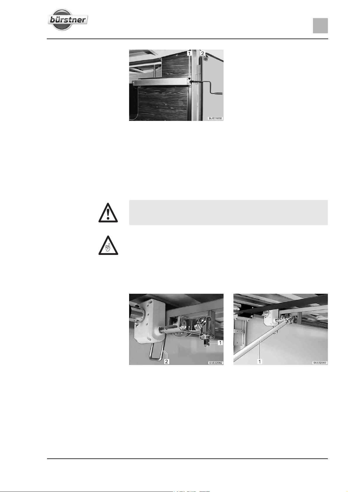
Living
Fig. 118 Crank in the rear garage
Attach the crank (Fig. 118,2) onto the journal (Fig. 118,1).
To lift the bed: Turn the crank clockwise.
To lower the bed: Turn the crank anticlockwise.
Remove the crank and store it.
6.14.4 Fixed bed, height adjustable via strap system (special equipment)
6
X Lower the bed to its lowest position to sleep in it.
Z Before using the bed, make sure that the lever of the locking device is in
the locked position (horizontal).
The height of the fixed bed can be adjusted via a crank in the rear garage.
The bed can be raised before setting off. This increases the storage space
under the bed.
Fig. 119 Height adjustment Fig. 120 Crank in the rear garage
Attach the crank onto the journal (Fig. 119,1).
Swivel the lever (Fig. 119,2) downwards into vertical position.
To lift the bed: Turn the crank (Fig. 120,1) clockwise.
To lower the bed: Turn the crank (Fig. 120,1) anticlockwise.
Swivel the lever (Fig. 119,2) upwards into horizontal position.
Remove the crank and store it.
93T-Modell - 17/18 - Ausgabe 09/17 - 2891569 - BUE-0029-19EN
Page 94
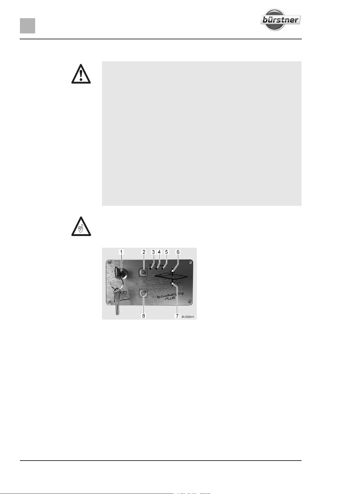
6
Living
6.14.5 Pull-down bed, electrically operated (Ixeo TL)
X The maximum permitted pull-down bed load is 200 kg.
X Do not reach into the area between the bed and the side wall when low-
ering or raising. Danger of bruises!
X Do not lower or lift the bed when there are people using the pull-down
bed.
X Only lower the bed if the lowering area is clear.
X Only lower the pull-down bed so far that it does not lie on any obstacles
such as headrests, cushions or anything similar. If possible, remove
such obstacles before lowering.
X Do not allow children to play with the pull-down bed.
X Store the key for the control unit such that children have no access to it.
X Only use the pull-down bed if the safety plates are inserted.
X Use separate children's beds or travel cots suitable for children.
X Never allow small children to remain in the pull-down bed without super-
vision.
X But in particular with regard to small children less than 6 years of age,
users should ensure that they cannot fall out of the pull-down bed.
Z Before starting a journey, the pull-down bed must be in the top end position.
Do not stow any bulky items or bedding on the pull-down bed so that the
pull-down bed can move to the top end position.
1 Key switch
2 UP button
3Alarm LED
4 Programme LED
5 RESET button (without function)
6UP LED
7DOWN LED
8 DOWN button
Fig. 121 Control unit
Control unit The pull-down bed is raised or lowered using the buttons (Fig. 121,2 and 8) on
the control unit (Fig. 121). The control unit is protected against unauthorized
use with the key switch (Fig. 121,1).
4 fixed positions of the pull-down bed are programmed at the factory:
Position 1: Top end position. The bed is in the ready-to-drive state.
Position 2: The bed moves down approx. 20 cm and lifts the head section.
Position 3: Top sleeping position. In this position you can use both the pulldown bed and the seating group under the pull-down bed to sleep on. This
position is adjusted to the ladder (special equipment) for climbing into the pulldown bed.
Position 4: Bottom sleeping position (bottom end position). The bed is lying on
the seat cushions and on the table.
94 T-Modell - 17/18 - Ausgabe 09/17 - 2891569 - BUE-0029-19EN
Page 95
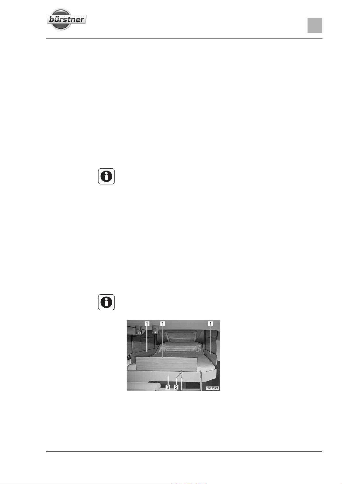
Living
6
Lowering the pull-down bed: Removing any obstacles in the area into which the pull-down bed extends:
Push the seats forwards and rotate, lower backrests, remove or fold cushions if necessary.
Switch off the lamps underneath the pull-down bed.
Turn the key in the key switch (Fig. 121,1) through 90° clockwise. The con-
trol unit (Fig. 121) is activated. Wait until both indicator lamps (Fig. 121,6
and 7) light up in green.
Press the arrow key (Fig. 121,8) and keep it pressed until the bed reaches
the next programmed position below. The green indicator lamp (Fig. 121,7)
is on while the bed is moving.
If necessary, press the arrow key (Fig. 121,8) again to reach the next posi-
tion.
Repeat the procedure until the desired position is reached.
Ensure that the pull-down bed is not resting on obstacles such as head-
rests, cushions or similar.
Z To prevent accidental incorrect operation, the key can be removed from the
key switch (Fig. 121,1). This necessitates the key being turned anticlockwise.
Lifting the pull-down bed:
Switch off the reading lamps in the pull-down bed.
Turn the key in the key switch (Fig. 121,1) through 90° clockwise. The con-
trol unit (Fig. 121) is activated. Both indicator lamps (Fig. 121,6 and 7) light
up in green.
Press the arrow key (Fig. 121,2) and keep it pressed until the bed reaches
the next programmed position above. The green indicator lamp (Fig. 121,6)
is on while the bed is moving.
If necessary, press the arrow key (Fig. 121,2) again to reach the next posi-
tion.
Repeat the procedure until the desired position is reached.
Ensure that there are no objects stuck between the roof and the pull-down
bed.
Z To prevent accidental incorrect operation, the key can be removed from the
key switch (Fig. 121,1). This necessitates the key being turned anticlockwise.
Fig. 122 Pull-down bed with safety
plates
Safety plates The safety plates are only required in the top sleeping position. The safety
plates are located underneath the mattress in the pull-down bed. Remove the
safety plates before using the pull-down bed but do not insert them until persons are already in the pull-down bed.
95T-Modell - 17/18 - Ausgabe 09/17 - 2891569 - BUE-0029-19EN
Page 96
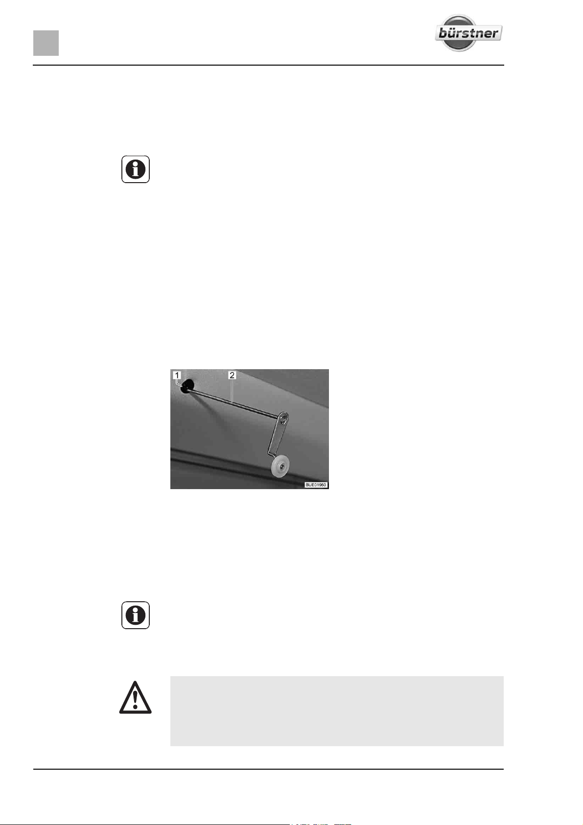
6
Living
Inserting the safety plates: Bring out the safety plates under the mattress and place them on the pull-
down bed.
Climb into the pull-down bed via the access ladder.
Insert the safety plates (Fig. 122,1) between the mattress and the bed sur-
round (Fig. 122,3).
Z Before the pull-down bed is pushed up: Remove the safety plates again
and place them under the mattress.
Access ladder (special
equipment)
Attaching:
If the pull-down bed is in the top sleeping position, only access the pull-down
bed using the access ladder.
Hook both bows of the access ladder (Fig. 122,2) into the bed surround
(Fig. 122,3).
Storing away:
Release the access ladder (Fig. 122,2) from the bed surround (Fig. 122,3).
Store the access ladder securely.
Emergency operation If it is no longer possible to move the pull-down bed with the arrow keys
(Fig. 121,2 and 8), first of all check the fuse Reserve 3 on the transformer/rectifier (see section 8.9.1). If the fuse is okay and it is still not possible to move
the pull-down bed, the pull-down bed can be operated manually.
Fig. 123 Crank for emergency operation
Remove the mattress from the pull-down bed.
Insert the crank (Fig. 123,2) provided or an Allen wrench into the accom-
modation (Fig. 123,1) on the motor. The holder is in the cut-out in the surround at the top left of the pull-down bed.
Turn crank or Allen wrench manually until the pull-down bed has reached
the upper parking position.
Z For instructions on troubleshooting, see section 14.12.
6.14.6 Pull-down bed, electrically operated (Ixeo Time, Lyseo TD)
X The maximum permitted pull-down bed load is 200 kg.
X Do not reach into the area between the bed and the side wall when low-
ering or raising. Danger of bruises!
X Do not lower or lift the bed when there are people using the pull-down
bed.
96 T-Modell - 17/18 - Ausgabe 09/17 - 2891569 - BUE-0029-19EN
Page 97
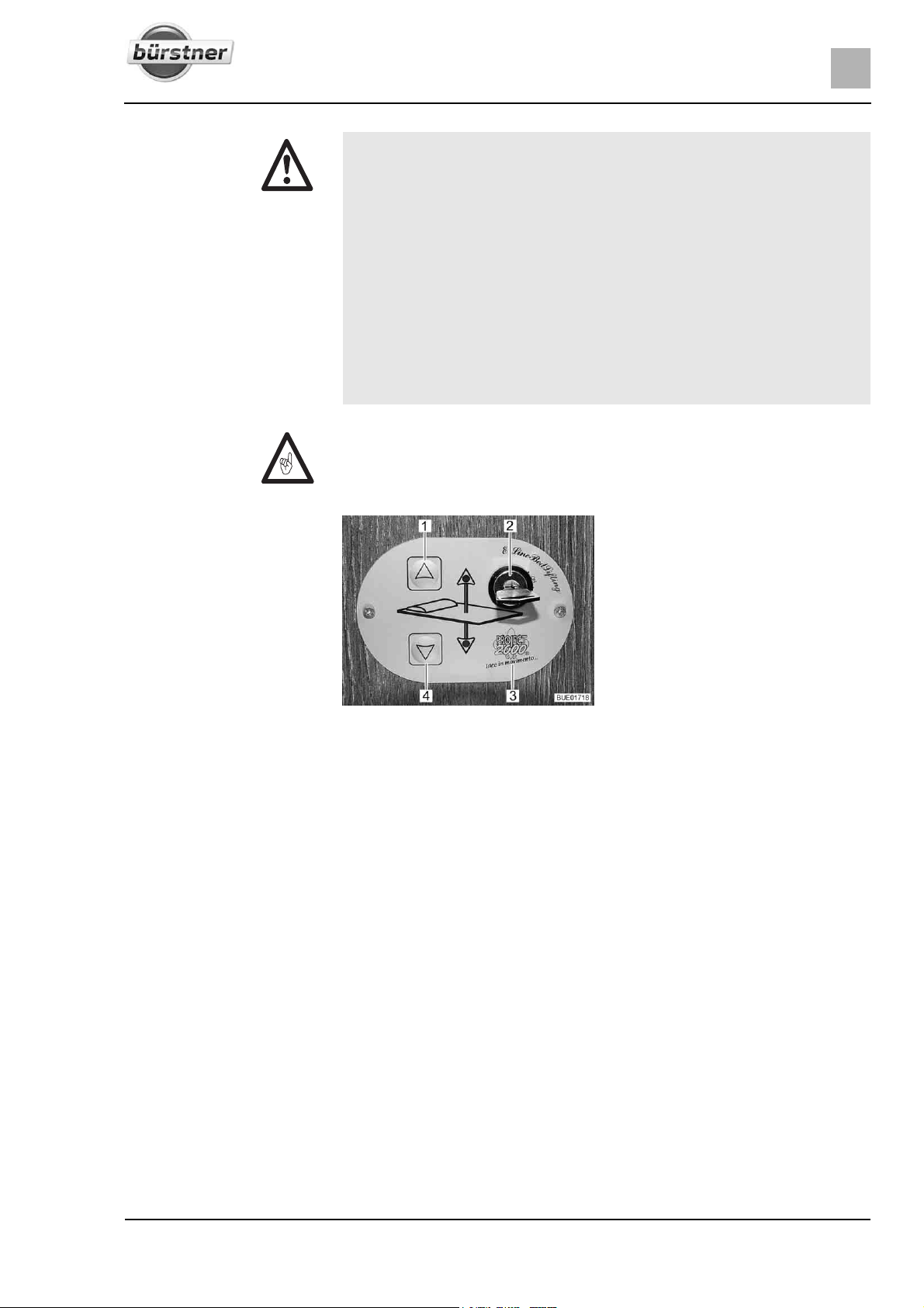
Living
X Only lower the bed if the lowering area is clear.
X Only lower the pull-down bed so far that it does not lie on any obstacles
6
such as headrests, cushions or anything similar. If possible, remove
such obstacles before lowering.
X Do not allow children to play with the pull-down bed.
X Store the key for the control unit such that children have no access to it.
X Only use the pull-down bed, if the safety net is set up.
X Use separate children's beds or travel cots suitable for children.
X Never allow small children to remain in the pull-down bed without super-
vision.
X But in particular with regard to small children less than 6 years of age,
users should ensure that they cannot fall out of the pull-down bed.
Z Before starting a journey, the pull-down bed must be in the top end position.
Do not stow any bulky items or bedding on the pull-down bed so that the
pull-down bed can move to the top end position.
Control unit The pull-down bed is raised or lowered using the buttons (Fig. 124,1 and 4) on
Lowering the pull-down bed:
Lifting the pull-down bed:
Fig. 124 Control unit
the control unit (Fig. 124,3). The control unit is protected against unauthorized
use with the key switch (Fig. 124,2).
The pull-down bed's height may be adjusted steplessly.
Removing any obstacles in the area into which the pull-down bed extends:
Push the seats forwards and rotate; remove or fold cushions if necessary.
Switch off the lamps underneath the pull-down bed.
Turn the key in the key switch (Fig. 124,2) by 90° in a clockwise direction
to position "On". The control unit (Fig. 124,3) is activated.
Press the arrow key (Fig. 124,4) and keep it pressed until the pull-down
bed has moved down into the desired position.
Ensure that the pull-down bed is not resting on obstacles such as head-
rests, cushions or similar.
Switch off the reading lamps in the pull-down bed.
Press the arrow key (Fig. 124,1) and keep it pressed until the pull-down
bed has moved down into the final upper position.
Ensure that there are no objects stuck between the roof and the pull-down
bed.
97T-Modell - 17/18 - Ausgabe 09/17 - 2891569 - BUE-0029-19EN
Page 98
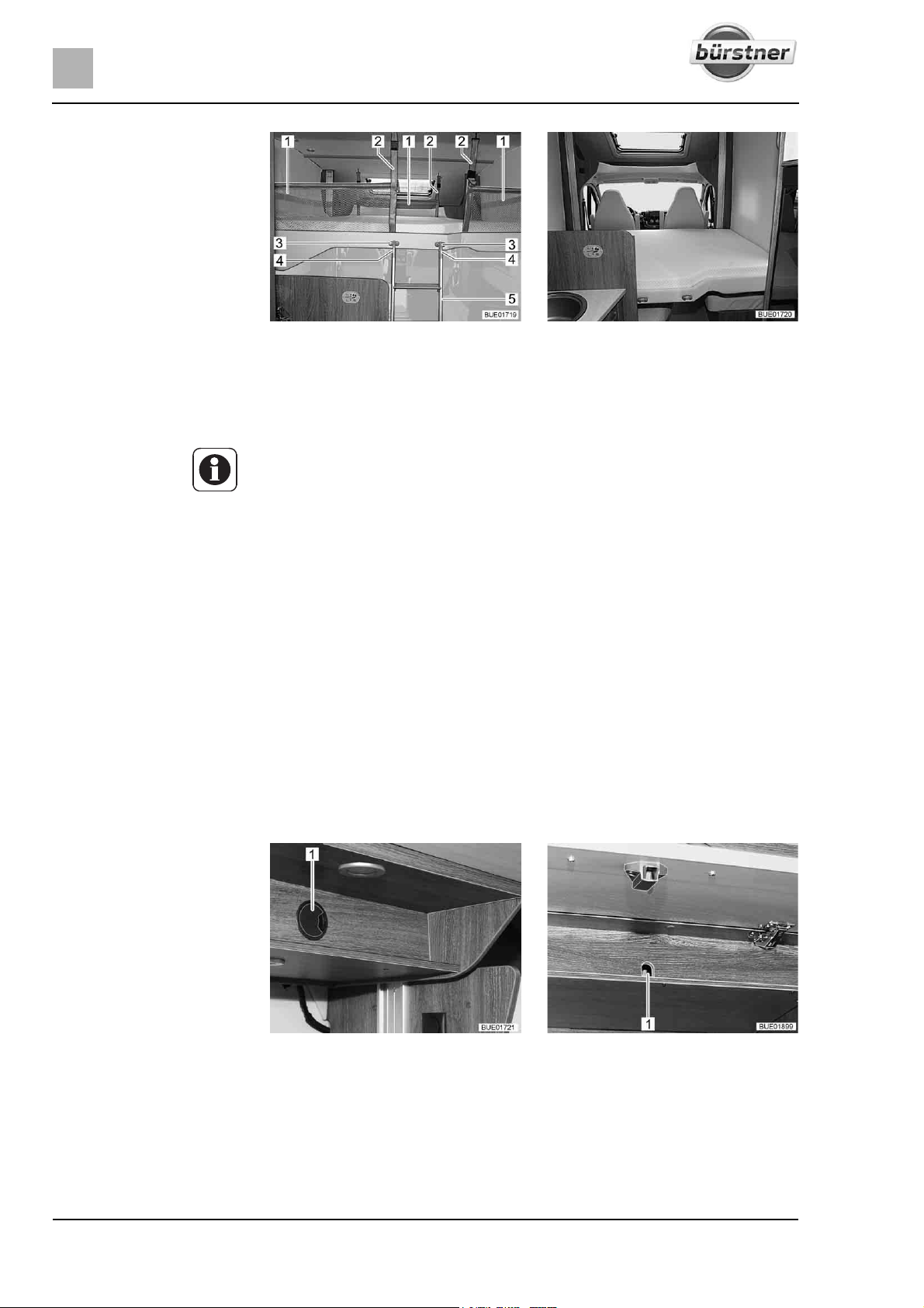
6
Living
Fig. 125 Pull-down bed complete with
Safety net The three safety nets (Fig. 125,2) with their retaining belts are located under-
neath the mattress in the pull-down bed. Only use the safety nets if persons
are already in the pull-down bed.
Z If the pull-down bed is lowered below 1 m (Fig. 126), it will not be possible
Setting up:
Access ladder If the pull-down bed is raised over 1 m, only access the pull-down bed using
Attaching:
Storing away:
Emergency operation If it is no longer possible to move the pull-down bed with the arrow keys
Attach retaining belts (Fig. 125,1) to the hooks on the ceiling.
the access ladder provided.
Hook both bows (Fig. 125,4) of the access ladder (Fig. 125,5) into the
Release the access ladder (Fig. 125,5) from the holders (Fig. 125,3).
Store the access ladder securely.
(Fig. 124,1 and 4), first of all check the fuse in the front wall-mounted cupboard
on the left-hand side of the vehicle or at Reserve 3 on the transformer/rectifier
(see section 8.9.1). If the fuse is okay and it is still not possible to move the
pull-down bed, the pull-down bed can be operated manually.
applied safety net
to set up the safety nets.
holders (Fig. 125,3).
Fig. 126 Pull-down bed, completely low-
ered (dependent on model)
Fig. 127 Access to drive Fig. 128 Access to drive (alternative)
If present, remove the cover from the access opening (Fig. 127,1 or
Fig. 128,1).
98 T-Modell - 17/18 - Ausgabe 09/17 - 2891569 - BUE-0029-19EN
Page 99
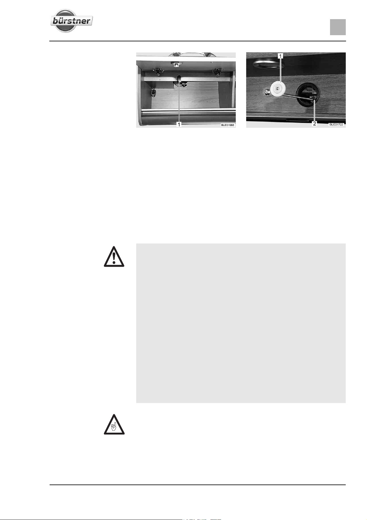
Living
Fig. 129 Access to drive (Lyseo) Fig. 130 Mechanical operation, drive
If the holder (Fig. 129,1) for the drive is installed in the wall-mounted cup-
6
board: open the wall-mounted cupboard.
Remove mattress from pull-down bed and reduce the load of the storage
cupboards to a minimum.
Insert the crank (Fig. 130,1) provided or an Allen wrench into the accom-
modation on the motor (Fig. 130,2 or Fig. 129,1).
Turn crank or Allen wrench manually until the pull-down bed has reached
the upper parking position.
6.14.7 Pull-down bed at the rear, electrically operated (Lyseo TD) (special equipment)
X Before setting off, always move the pull-down bed into the top end posi-
tion.
X The maximum permitted pull-down bed load is 200 kg.
X Do not reach into the area between the bed and the side wall when low-
ering or raising. Danger of bruises!
X Do not lower or lift the bed when there are people using the pull-down
bed.
X Only lower the bed if the lowering area is clear.
X Only lower the pull-down bed so far that it does not lie on any obstacles
such as headrests, cushions or anything similar. If possible, remove
such obstacles before lowering.
X Do not allow children to play with the pull-down bed.
X Store the key for the control unit such that children have no access to it.
X Use separate children's beds or travel cots suitable for children.
X Never allow small children to remain in the pull-down bed without super-
vision.
X But in particular with regard to small children less than 6 years of age,
users should ensure that they cannot fall out of the pull-down bed.
Z Before starting a journey, the pull-down bed must be in the top end position.
Do not stow any bulky items or bedding on the pull-down bed so that the
pull-down bed can move to the top end position.
99T-Modell - 17/18 - Ausgabe 09/17 - 2891569 - BUE-0029-19EN
Page 100
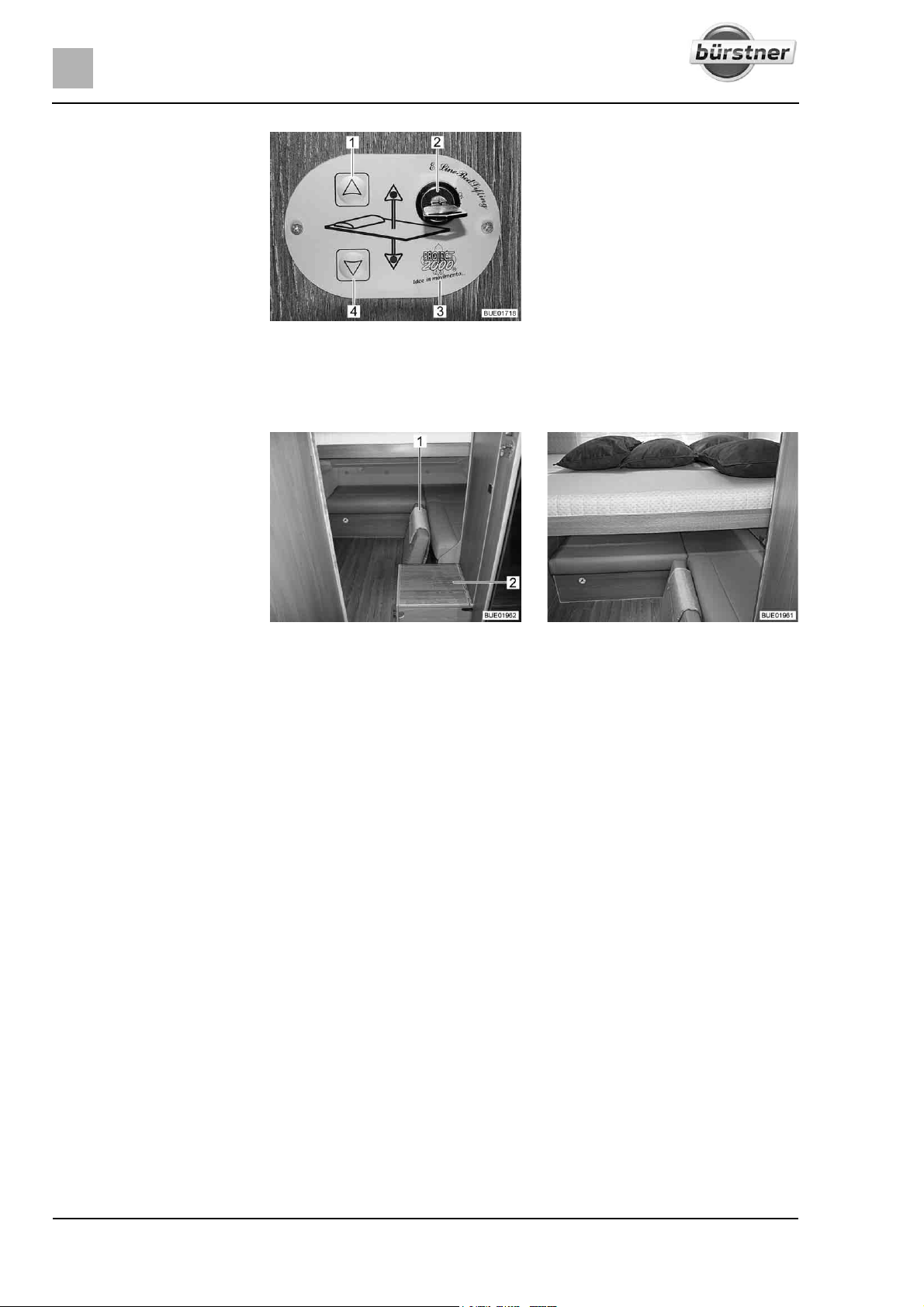
6
Living
Fig. 131 Control unit
Control unit The pull-down bed is raised or lowered using the buttons (Fig. 131,1 and 4) on
the control unit (Fig. 131,3). The control unit is protected against unauthorized
use with the key switch (Fig. 131,2).
Lowering the pull-down bed:
Lifting the pull-down bed:
Access assistance The storage compartment (Fig. 132,2) can be used as an access assistance.
Fig. 132 Storage compartment and
removed back cushion
Remove back cushion (Fig. 132,1) of the rear seating group.
Remove any other obstacles in the area into which the pull-down bed
Fig. 133 Pull-down bed at the rear, low-
ered
extends, e.g. bring the television into driving position.
Switch off the lamps underneath the pull-down bed.
Turn the key in the key switch (Fig. 131,2) through 90° clockwise. The con-
trol unit (Fig. 131,3) is activated.
Press the arrow key (Fig. 131,4) and keep it pressed until the pull-down
bed has moved down into the desired position.
Make sure that the pull-down bed is not resting on obstacles such as cush-
ions or similar.
Switch off the reading lamps in the pull-down bed.
Press the arrow key (Fig. 131,1) and keep it pressed until the pull-down
bed has moved down into the final upper position.
Ensure that there are no objects stuck between the roof and the pull-down
bed.
100 T-Modell - 17/18 - Ausgabe 09/17 - 2891569 - BUE-0029-19EN
 Loading...