

Page 1

OPERATING MANUAL
ForceMaster 9110
©2013 burster
Manufacturer:
burster präzisionsmesstechnik gmbh & co kg
Talstraße 1 – 5
Germany
P.O.Box 1432
Germany
Valid from:
08.10.2013
Tel.:
(+49) 07224 / 6450
Fax.:
(+49) 07224 / 64588
E-Mail:
www.burster.de
1378-BA9110EN-5170-101523
präzisionsmesstechnik gmbh & co kg
All rights reserved
76593 Gernsbach
76587 Gernsbach
Page 2

Warranty - exclusion of liability
All information in the present documentation was prepared and compiled with great care and reproduced
subject to effective control measures. No warranty is provided for freedom from errors. We reserve the
right to make technical changes. The present information as well as the corresponding technical data can
change without notice. Reproduction of any part of this documentation or its processing or revision using
electronic systems is prohibited without the manufacturer's prior written approval.
Components, devices and measured value sensors made by burster präzisionsmesstechnik (hereinafter
referred to as "product") are the results of targeted development and meticulous research. As of the date
of delivery, burster provides a warranty for the proper condition and functioning of these products covering
material and production defects for the period specified in the warranty document accompanying the
product. However, burster excludes guarantee or warranty obligations, as well as any liability beyond that,
for consequential damages caused by improper use of the product, in particular the implied warranty of
success in the market as well as the suitability of the product for a particular purpose. Furthermore,
burster assumes no liability for direct, indirect or incidental damages as well as consequential or other
damages arising from the provision and use of the present documentation.
Page 3
Page 4

4
of 95
Page 5
Contents
1. For your safety ................................................................................................................................................... 9
2. Introduction ...................................................................................................................................................... 10
2.1 Intended use ...................................................................................................................................... 10
2.2 Ambient conditions ............................................................................................................................ 10
2.2.1 Storage conditions ............................................................................................................ 10
2.2.2 Conditions of use .............................................................................................................. 10
2.3 Personnel .......................................................................................................................................... 11
2.4 Scope of supply ................................................................................................................................. 11
2.5 Conversions and modifications ......................................................................................................... 11
3. Device concept ................................................................................................................................................. 12
3.1 Range of functions ............................................................................................................................ 12
3.2 Simple operation................................................................................................................................ 12
3.3 Autoconfiguration .............................................................................................................................. 12
3.4 Counter .............................................................................................................................................. 12
3.5 Documentation of measuring operations .......................................................................................... 12
3.6 Languages ......................................................................................................................................... 13
3.7 Support for automation ...................................................................................................................... 13
3.8 Front view of the ForceMaster 9110 ................................................................................................. 14
3.9 Rear view of the ForceMaster 9110 .................................................................................................. 15
3.10 Menu structure of the
3.10.1 Operating example (extract from the menu) ..................................................................... 19
3.10.2 Aids to orientation for operation ........................................................................................ 19
3.10.3 Display and operating concept ......................................................................................... 20
3.10.4
Entering text and numbers ................................................................................................ 21
3.11 Autoconfiguration .............................................................................................................................. 22
3.11.1 "Autoconfig" menu ............................................................................................................ 22
3.11.2 "Step 1: teach-in" .............................................................................................................. 23
3.11.3 "Step 2: Set Modes" .......................................................................................................... 23
3.11.4 "Step 3: Set values" .......................................................................................................... 25
3.11.5 Finish autoconfiguration .................................................................................................... 27
3.12 Card reader ....................................................................................................................................... 28
3.12.1 MasterCard ....................................................................................................................... 28
3.12.2 ToolCard ........................................................................................................................... 28
3.12.3 PLCCard ........................................................................................................................... 28
3.13 "PLC & IO" menu ............................................................................................................................... 29
3.13.1 List of possible conditions ................................................................................................. 32
ForceMaster 9110
....................................................................................... 16
5 of 95
Page 6
3.13.2 List of possible commands ............................................................................................... 33
3.14 "Cam" menu ...................................................................................................................................... 33
3.15 Measuring and adjusting ................................................................................................................... 35
3.16 Force alarms ...................................................................................................................................... 35
3.16.1 Force alarm 1 .................................................................................................................... 35
3.16.2 Force alarm 2 .................................................................................................................... 35
3.17 Step chain controller (option) ............................................................................................................ 36
3.18 Cam switching mechanism ................................................................................................................ 37
3.19 I/O interface ....................................................................................................................................... 38
3.19.1 Connector pin assignments .............................................................................................. 38
3.19.2 I/O signal combinations .................................................................................................... 39
3.20 Switching on procedure ..................................................................................................................... 40
4. Initial commissioning ...................................................................................................................................... 41
4.1 Fitting the load cell to the manual press ............................................................................................ 41
4.2 Fitting the displacement measurement system (DMS) to the manual press .................................... 42
4.3 Setting up the measurement chain on the ForceMaster 9110 .......................................................... 44
5. Measurement .................................................................................................................................................... 46
6. Configuring the ForceMaster 9110 settings .................................................................................................. 49
6.1 "Counter" menu ................................................................................................................................. 50
6.2 USB stick (option) .............................................................................................................................. 52
6.2.1 Operation with a USB stick ............................................................................................... 52
6.2.2 "USB stick" menu .............................................................................................................. 53
6.2.3 Data storage example ....................................................................................................... 57
6.3 "PLC & IO" menu ............................................................................................................................... 58
6.3.1 List of possible conditions ................................................................................................. 61
6.3.2 List of possible commands ............................................................................................... 62
6.4 "Cam" menu ...................................................................................................................................... 62
6.5 "CARD" menu .................................................................................................................................... 64
6.6 "Manual settings"" menu. .................................................................................................................. 67
6.7 "Error signals" menu .......................................................................................................................... 69
6.8 "Order data" menu ............................................................................................................................. 72
6.9 "Statistics" menu ................................................................................................................................ 74
6.10 "Manual and internal settings" menu ................................................................................................. 75
6.11 "Date & time" menu ........................................................................................................................... 80
6.12 "Status" menu .................................................................................................................................... 81
6.13 "Languages" menu ............................................................................................................................ 81
6 of 95
Page 7
7.
Force-displacement curves ............................................................................................................................ 82
8. Technical data .................................................................................................................................................. 89
9. Configuration notes ......................................................................................................................................... 90
9.1 Choosing the right load cell ............................................................................................................... 90
9.2 Choosing the right displacement sensor ........................................................................................... 91
9.3 Advice ................................................................................................................................................ 91
10. Available accessories ...................................................................................................................................... 92
11. Ordering example ............................................................................................................................................ 93
12. Index .................................................................................................................................................................. 94
7 of 95
Page 8
8 of 95
Page 9
For your safety
can
1. For your safety
The following symbols on the device and in this manual warn of hazards:
Symbols in the manual
Warning
Death or serious injury
Caution
occur if no appropriate precautions are taken.
Damage to property can occur if no appropriate precautions are taken.
Note
Symbols on the device
It is important to heed these safety notices in order to ensure correct handling of the
instrument.
Observe the text on the device
Observe the text next to/underneath the warning sign:
"Unplug the mains before opening! - Observe safety instruction - Servicing only by trained
technicians"
9 of 95
Page 10

Intended use
2. Introduction
2.1 Intended use
The ForceMaster 9110 is a device for monitoring repetitive production processes. Its particular
purpose is the recording and evaluation of process signals, where the curve of the force has a
defined relationship with displacement or time. The result of the analysis is classified as either
ACCEPTABLE (OK) or is NOT acceptable (NOK). Visual and acoustic signals are given, and
made available at various interfaces.
The device is not a replacement for safety equipment, such as for the emergency shutdown of a
press if the pressing force exceeds a limit value.
2.2 Ambient conditions
2.2.1 Storage conditions
• clean packaging
• dry
• no condensation
• temperature between 0 °C and +60 °C
2.2.2 Conditions of use
• indoors
• maximum altitude: 2000 m above sea level
• operating temperature: between +5 °C and +40 °C
• humidity: 80% up to 31 °C, decreasing linearly above that temperature to 50%
at T
, no condensation
max
• protection class:1
• transient excess voltage: according to Category 2
• potential to ground: ≤ 12 V DC between analog ground and ground
• supply voltage: 90 to 264 V
, 47 to 63 Hz
eff
10 of 95
Page 11

Introduction
2.3 Personnel
The operating personnel must be familiar with the respectively applicable regulations. They must
follow these regulations.
2.4 Scope of supply
• ForceMaster 9110
• Operating manual
• 1 x mains cable
• PC software
• MasterCard 9110-Z001
2.5 Conversions and modifications
If you open up the ForceMaster 9110 or dismantle it during the warranty period, the warranty will
be immediately voided.
The ForceMaster 9110 may only be opened by our technical personnel.
It is forbidden to make any modification to the ForceMaster 9110 without our written permission.
In that case we can accept no liability.
11 of 95
Page 12

Range of functions
3. Device concept
3.1 Range of functions
The ForceMaster 9110 is a measuring instrument that monitors production operations at manual
presses by measuring the applied force and the distance travelled by the punch.
The design includes mechanisms that make sure that reported errors cannot be ignored.
3.2 Simple operation
Bei der Entwicklung des ForceMaster 9110 wurde auf einfache Bedienung großer Wert gelegt. Es
gibt nur einen Bedienknopf, der genügt, um durch das Menü zu navigieren.
3.3 Autoconfiguration
The work required to set up the ForceMaster 9110 has been simplified through the introduction of
an autoconfiguration system. You carry out the pressing of a part as an example, and the
ForceMaster 9110 records the pressing forces and the distance.
This makes all settings automatically. Whether the sensors are of F or F/s type is also detected.
The measuring mode is set automatically. Units such as newtons (N), kilonewtons (kN) or
displacement (mm) are set automatically.
3.4 Counter
The ForceMaster 9110 counts the number of parts that have been checked, recording both the
total number of parts as well as how many were assessed as OK and how many were NOK (not
OK). In practice, the number of parts that are assessed as NOK must be the same as the number
of parts in the scrap box at the manufacturing station. In this way you can also check whether the
worker has correctly sorted out the scrap parts.
3.5 Documentation of measuring operations
The ForceMaster 9110 offers several options for documenting production quality. You are also
able to write up to 50 manufacturing jobs into a job memory, transfer this to an Excel table, and
store it on a USB stick.
It must be possible to trace the documentation back to the individual manufacturer part. This is
only possible if a large amount of memory is available and if the data can be handled easily.
These facilities are provided by a USB stick.
12 of 95
Page 13

Device concept
Two recording modes are available to you. A CSV file is generated in both cases. Many
statistical programs (e.g. Excel, Access) can process this format.
• A job file records the data measured for each part, including what force was
reached, and whether the part was OK.
• A menu allows you to choose whether the entire pressing curve is to be stored.
Because a pressing curve contains a relatively large amount of data, the
storage process takes up to 3 seconds. In addition, this data record takes a
correspondingly large amount of storage on the stick.
It is possible to collect the accumulated data daily, and to use another stick for the following day.
The data that has been collected can then be saved on a PC or a server.
The large amount of storage available on a USB stick makes it possible to store the
documentation over a longer period of time. You should, however, evaluate the data regularly, so
that anything learnt from it can promptly be used to modify the production process.
3.6 Languages
The ForceMaster 9110 can be set for operation in a number of languages. See Section 6.15 for
the available languages.
3.7 Support for automation
The ForceMaster 9110 has a simple, freely programmable step chain controller, is supported in
addition by a cam switching mechanism. This allows simple, small-scale automation to be
implemented. There are 6 cams. Control signals can be triggered by these cams. Each cam can
be programmed in a variety of ways. The cam signals can exclusively be used through the
optional step chain controller.
13 of 95
Page 14
Support for automation
Key
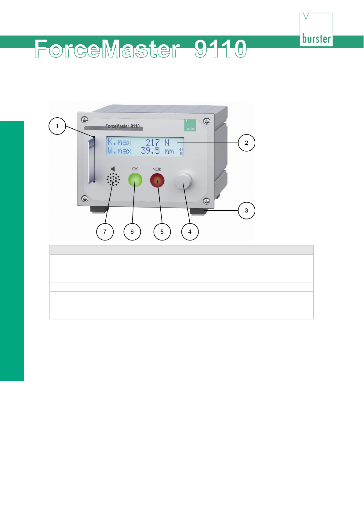
Explanation
4
Operating knob
5
Red indicator lamp NOK
6
Green indicator lamp OK
7
Loudspeaker
3.8 Front view of the ForceMaster 9110
1 Card reader
2 Two-line display
3 Folding feet
14 of 95
Page 15
Device concept
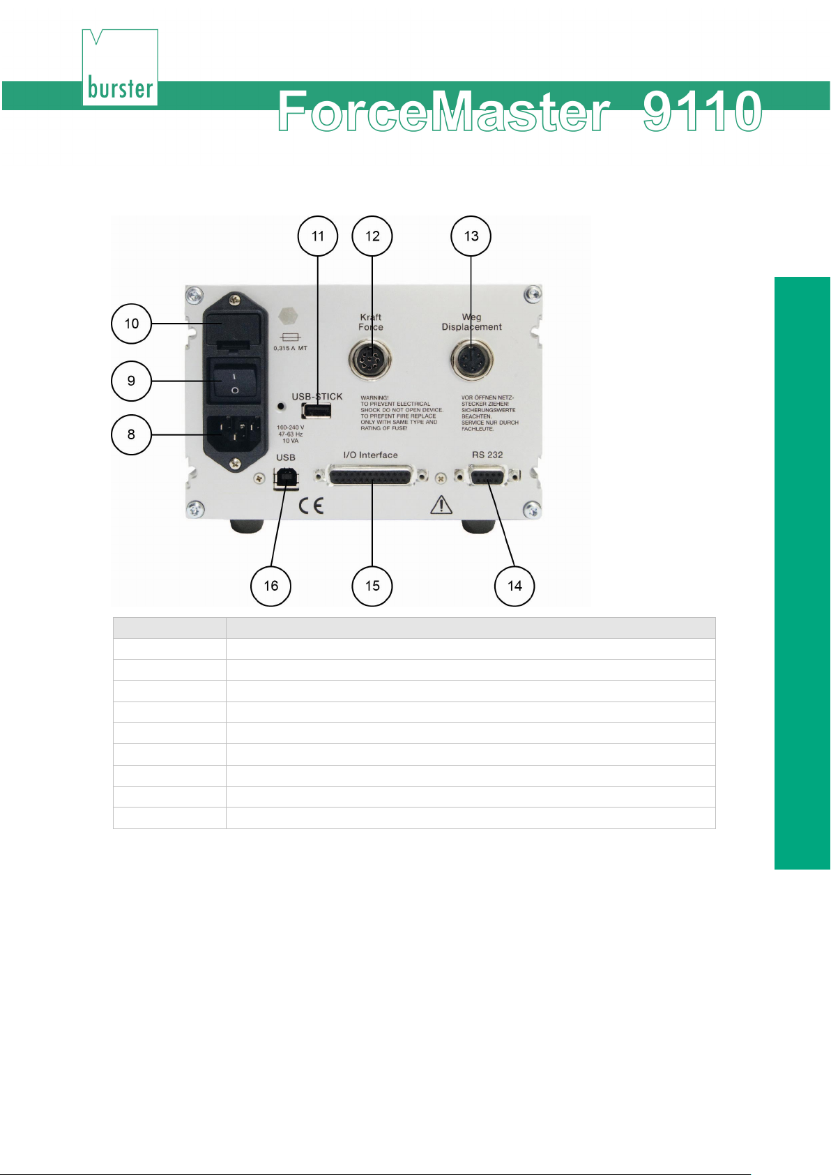
Key
Explanation
9
Mains switch
10
Fuse
11
Connection for USB stick (optional)
12
Connection for load cell
16
USB connection for PC
3.9 Rear view of the ForceMaster 9110
8 Mains connection
13 Connection for displacement sensor
14 RS232 interface
15 I/O interface
15 of 95
Page 16

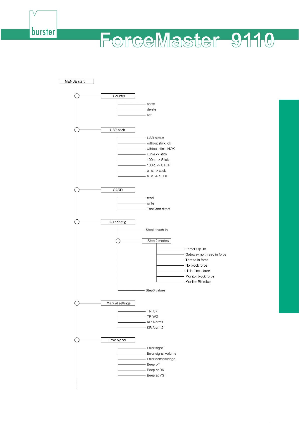
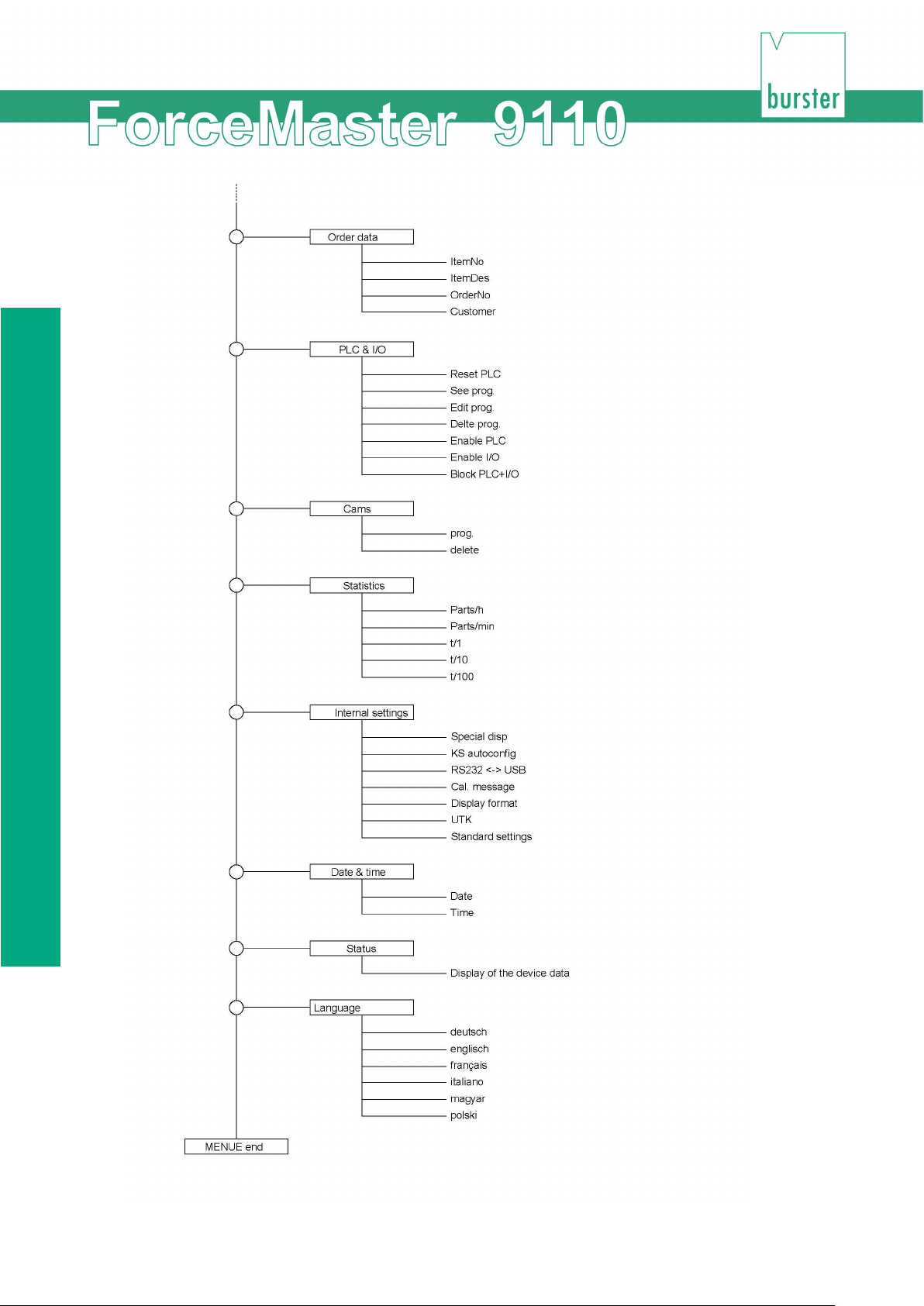
Menu structure of the ForceMaster 9110
3.10 Menu structure of the
ForceMaster 9110
16 of 95
Page 17
Device concept
17 of 95
Page 18
Menu structure of the ForceMaster 9110
18 of 95
Page 19
Device concept
Man. Einstell.
Fehlersignale
Fehlersignal
Fehl.sig.lautst.
Fehler quit
Beep aus
Beep bei BK
Beep VST
^^^^^
Unter-
Auftragsdaten
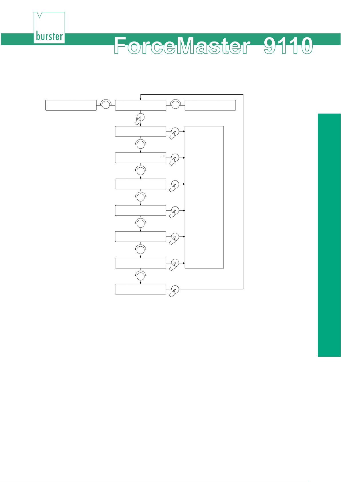
3.10.1 Operating example (extract from the menu)
funktion
Extract from the setting menu
The menu structure of the ForceMaster 9110 has been kept simple.
Like PC applications, there is a main menu. When you select a menu item, you are taken to a
sub-menu.
3.10.2 Aids to orientation for operation
Arrows that indicate the possible directions of rotation are provided on the lower right of the
display, immediately next to the rotary knob, for better orientation in the menu.
If the arrow points to the left (<) or to the right (>) you can turn the operating knob to the left or
right in order to reach a menu item.
19 of 95
Page 20
Menu structure of the ForceMaster 9110
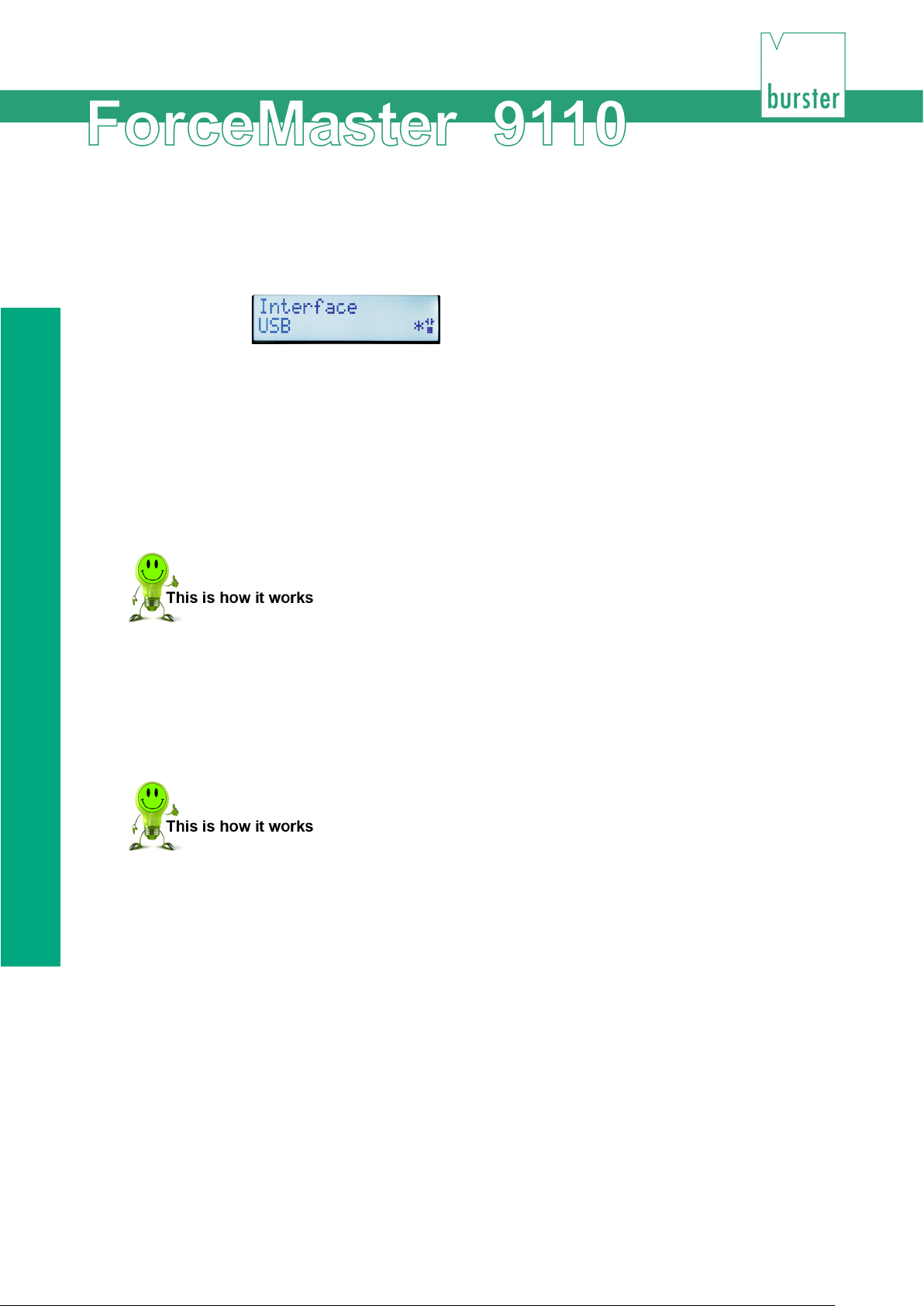
Note
There are menu functions that can be switched on or off.
An asterisk (*) appears at the end of the line if the function is switched on, so that
you can see the status straightaway.
3.10.3 Display and operating concept
A single knob, which you can turn and press, serves as the operating element.
When you have found the menu item where you want to change something, press the operating
knob. This takes you to a sub-menu. By turning the operating knob, you can navigate through the
sub-menu. When you have found the function you want, press the knob in order to select it.
1 Turn the operating knob until the menu item you want appears on the
display.
2 Press the operating knob in order to select the menu item.
To return from a sub-menu back to the main menu, turn the operating knob to the last menu item,
represented by arrows (^^^^^), and select it.
1 Turn the operating knob until the row of arrows (^^^^^) appears on the
display.
2 Press the operating knob to go to the main menu.
20 of 95
Page 21
Device concept
3.10.4
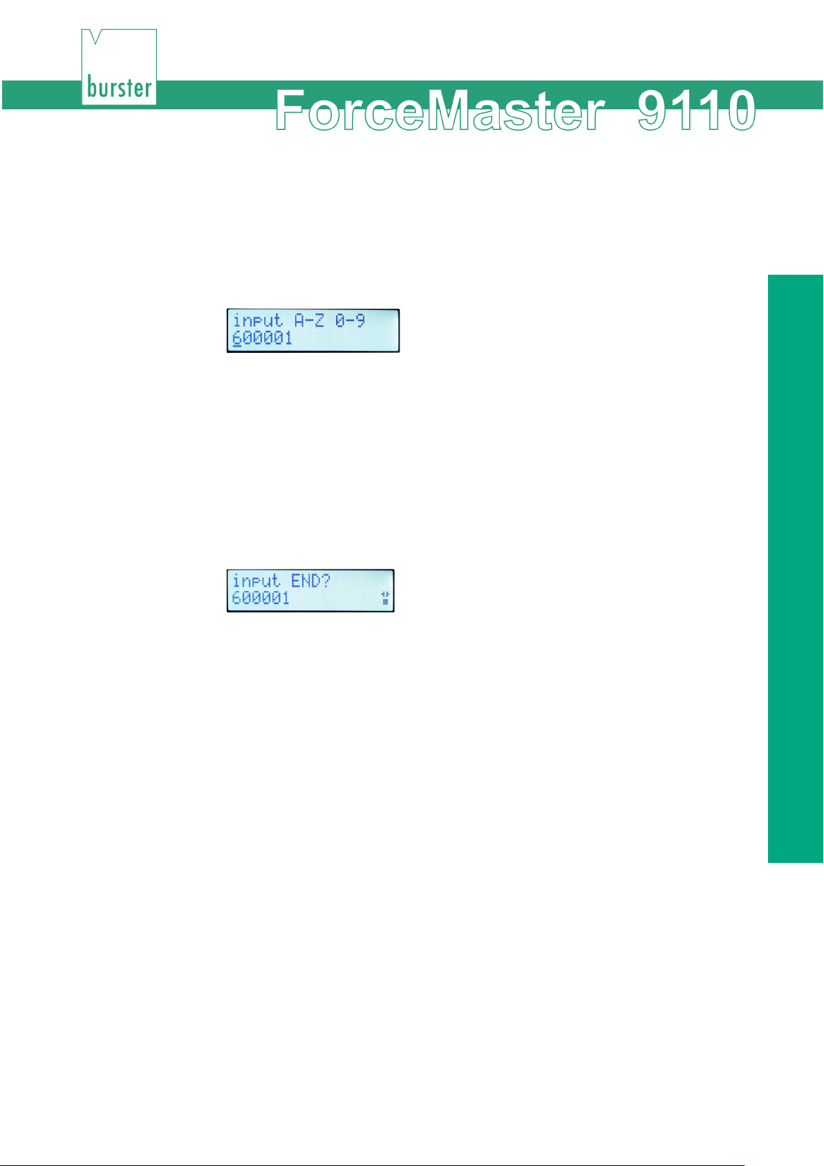
Text and numbers are input in order to make the settings in some of the menu items.
Entering text and numbers
1 Turn the operating knob to move the cursor to the location in the text that
you want to change.
2 Press the knob in order to select the text location.
3 Turn the operating knob in order to select the letter or the number that you
want.
4 Press the button again in order to confirm the selection.
5 Repeat steps 1 - 4 for every location in the text that you would like to
change.
6 In order to end the text input, move the cursor past the last location on the
line.
"input END?" then appears on the display.
7 Confirm that you are ending the input by pressing the operating knob.
3 When the pressing operation is complete, the numeric display shows "Step
2 set modes“.
21 of 95
Page 22
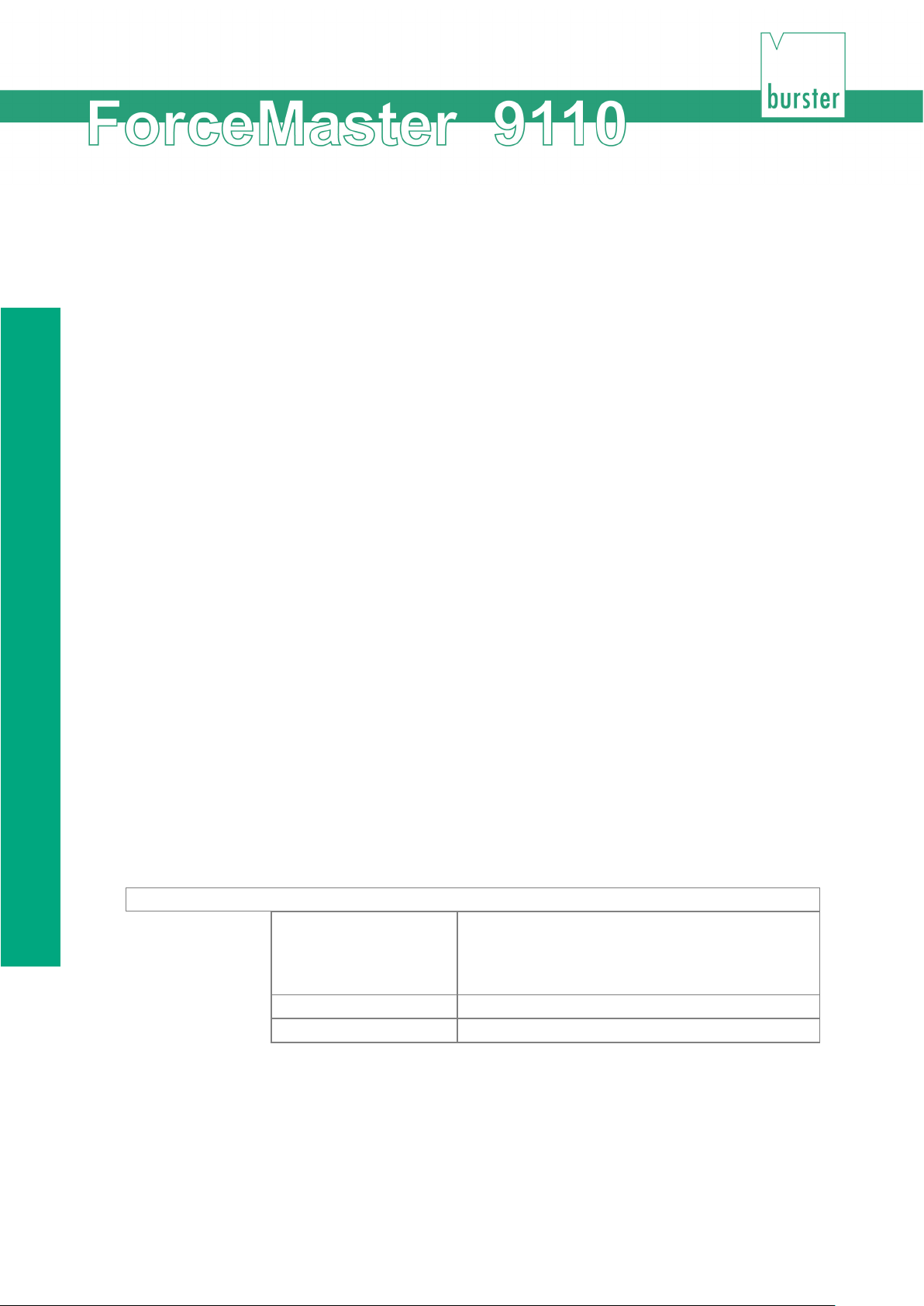
Autoconfiguration
A
utoc
onfig
Step 1 teach-in
Choose this menu item to start a teaching
Step 2 Modes
Choose this menu item to correct the modes.
Step 3 Values
Choose this menu item to correct the values.
3.11 Autoconfiguration
Autoconfiguration allows two aspects of the ForceMaster 9110 to be dealt with quickly and easily.
The ForceMaster 9110 detects the sensors that have been connected, and a teaching process
takes place in order to find the optimum monitoring values for the parts to be checked.
• Always start setting up the ForceMaster 9110 with an autoconfiguration.
If you want to correct the monitoring values manually at a later stage, you must first carry out an
autoconfiguration.
When you start the autoconfiguration, the ForceMaster 9110 will offer you the most reasonable
monitoring mode, according to whatever sensors you have connected.
The autoconfiguration brings you to an automated result in three steps. These three steps are:
Step 1: Teaching
The connected sensors and their attachment are detected automatically, and the teaching
process is initiated. Process a workpiece. Based on this process, the ForceMaster 9110 analyses
the force-displacement profile and offers a setting for the monitoring modes and monitoring
parameters.
Step 2: Setting the modes
You can check which monitoring modes the ForceMaster 9110 suggests, and are able to specify
a different one.
Step 3: Setting the parameters
You can check what monitoring parameters have been found by the ForceMaster 9110 for the
individual monitoring regions, and have the option of correcting them.
You then change to the measuring mode. You are also able to return to Step 1, and to run
through the autoconfiguration again with other parts.
3.11.1 "Autoconfig" menu
This menu offers you a way to get into the autoconfiguration.
process.
This is the usual starting point for a part that is to
be trained for the first time.
For a new part, start with "teach-in", and you will then be taken through all the following points.
For corrections (without a new teaching session), either choose "Step 2" to correct the modes, or
choose "Step 3" to correct the monitoring values.
If you have changed the values so much that it's no longer possible to take reasonable
measurements, then start a new autoconfiguration with "Teaching" in order to get to sensible
values again.
22 of 95
Page 23

Device concept
3.11.2 "Step 1: teach-in"
Always start the settings for a new part with a Teaching.
1 Open the "Autoconfiguration" menu.
2 Press the operating knob in order to select "Step 1 teach-in".
The display now shows: "waiting: downwards".
3 Carry out a pressing operation.
After you have pressed a part, but before you move the punch upwards again,
the display shows "waiting: upwards".
4 Move the punch back up.
When the pressing operation is complete, the display shows "Step 2 Set
modes".
It may be necessary to correct the values learnt through the autoconfiguration. If
necessary, they can be adjusted manually.
3.11.3 "Step 2: Set Modes"
In this step you can set the modes that are possible for monitoring. Selected modes are indicated
by a star.
In the pressing region you choose between force-displacement thresholds and five force
gateways. You can switch monitoring of the thread in force on or off.
23 of 95
Page 24
Autoconfiguration
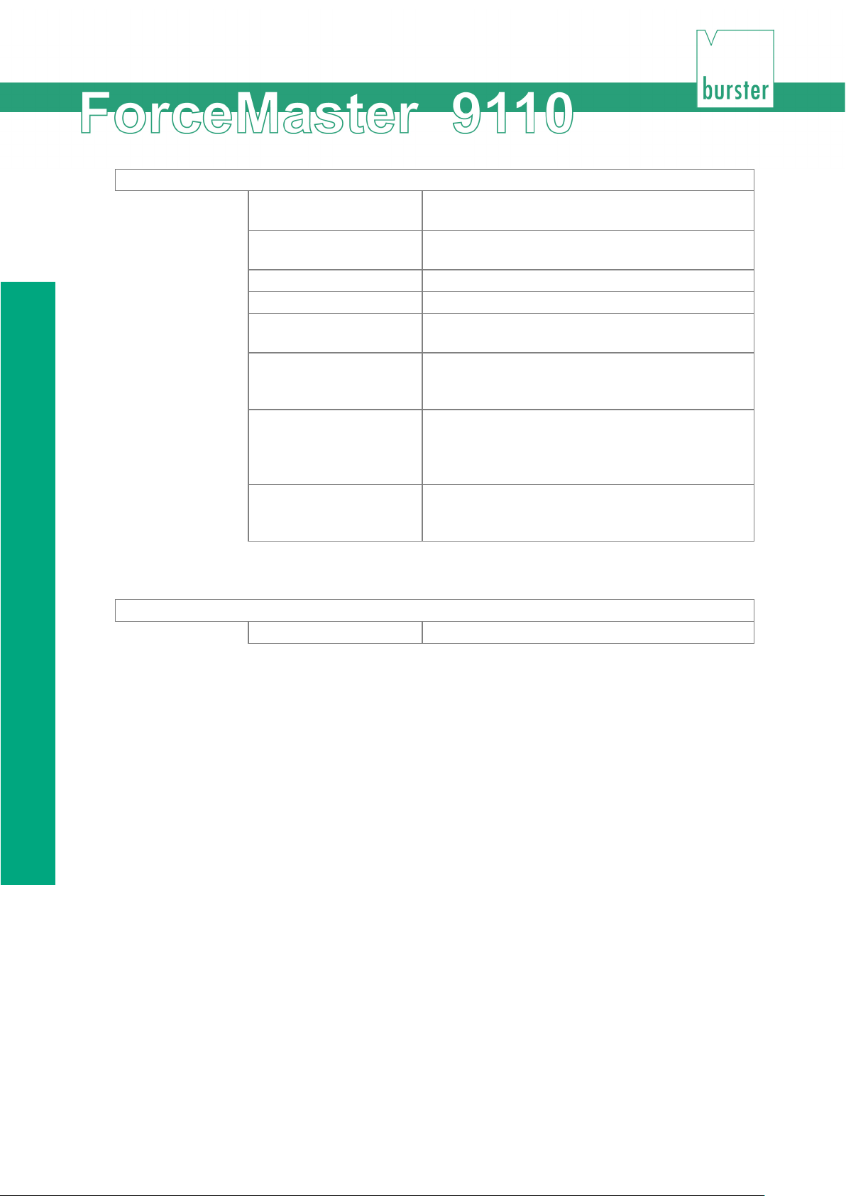
Step 2 Set modes
Means that force-displacement thresholds are
Gateways
No thread in force
Means that there is no thread in force.
No blocking force
Means that no monitoring takes place in the
Monitor blocking force
Means that between the start and end of blocking
must not be exceeded here.
Monitor the blocking
displacement
Means that the blocking force and the peening
Step 2 Set modes
Force thresholds
Means that force thresholds are monitored
Force-displacement
thresholds
Thread in force Means that there is an thread in force.
Hide blocking force Means that the curve must stop between the start
monitored.
Means that gateways specified in the force profile
are monitored.
blocking force region.
and end of blocking. There is no force monitoring
in this region.
the curve must reach the lower blocking force
threshold. The upper blocking force threshold
force + peening
If only forces monitored, only one mode is available:
displacement are monitored.
Setting the modes
1 Open the "Set modes" sub-menu.
2 Select the mode that you want to set.
4 Press the operating knob to confirm the setting.
24 of 95
Page 25
Device concept
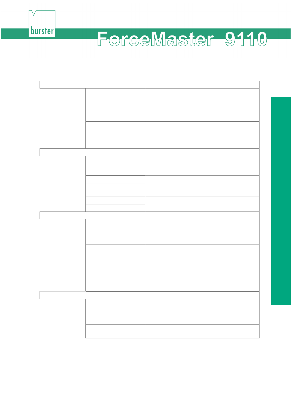
Set level
Displacement high
The end of the pressing phase.
Force high
The force threshold that the pressing force must
Set gateways
T1 lo
These values are to be set if you chose the
T1 hi
The upper force value of the gateway.
T2 lo
You can specify up to five gateways.
Set blocking
Displacement low
These values are to be set if you chose the
Force low
The force threshold that the blocking force must at
Force high
The force threshold that the blocking force must
Set the peening displacement
Pdisp min
These values are to be set if you chose the
Pdisp max
The peening displacement that must not be
3.11.4 "Step 3: Set values"
Displacement low These values are to be set if you chose the
"Force-displacement thresholds" item in Step 2.
"Displacement low" is the beginning of the
pressing phase.
Force low The force threshold, that the pressing force must
at least reach.
not exceed.
"Gateways" item in Step 2. "lo" is the lower force
value of the gateway.
T1 WG The displacement value at which the gateways
evaluated.
…
"Monitor blocking force" item in Step 2.
"Displacement low" is the beginning of the
blocking force monitoring.
Displacement high The end of the blocking force monitoring.
least reach. (Omitted in the "Hide blocking force"
mode)
not exceed. (Omitted in the "Hide blocking force"
mode)
"Monitor blocking force + Pdisp" item in Step 2.
"Pdisp min" is the peening displacement that must
be reached as a minimum.
exceeded.
25 of 95
Page 26
Autoconfiguration
Set thread in force
FIdisp high
These values are to be set if you chose the
FIforce high
The threshold that the thread in force must not
exceed.
Set level
Force high
The force threshold that the pressing force must
"Thread in force" item in Step 2. "FIdisp" high is
the final position, up to which the thread in force is
monitored.
The following limit values can be set when only force is monitored:
Force low The force threshold, that the pressing force must
at least reach.
not exceed.
Set the values for the force thresholds (pure force monitoring) or forcedisplacement thresholds
1 Open the "Set values" menu.
2 Press the operating knob in order to select the "Set level" menu item.
3 Select the value that you want to set.
4 Turn the operating knob in order to set the value.
5 Press the operating knob to confirm the setting.
Set the values of the gateways
1 Open the "Set values" menu.
2 Turn the operating knob until the "Set gateways" menu item appears.
3 Press the operating knob in order to select the menu item.
4 Select the value that you want to set.
5 Turn the operating knob in order to set the value.
6 Press the operating knob to confirm the setting.
26 of 95
Page 27

Device concept
Set the values of the blocking force monitoring
1 Open the "Set values" menu.
2 Turn the operating knob until the "Set blocking" menu item appears.
3 Press the operating knob in order to select the menu item.
4 Select the value that you want to set.
5 Turn the operating knob in order to set the value.
6 Press the operating knob to confirm the setting.
Set the values for the peening displacement
1 Open the "Set values" menu.
2 Turn the operating knob until the "Set peening displacement" menu item appears.
3 Press the operating knob in order to select the menu item.
4 Select the value that you want to set.
5 Turn the operating knob in order to set the value.
6 Press the operating knob to confirm the setting.
Set the values of the thread in force monitoring
1 Open the "Set values" menu.
2 Turn the operating knob until the "Set thread in force menu item appears.
3 Press the operating knob in order to select the menu item.
4 Select the value that you want to set.
5 Turn the operating knob in order to set the value.
6 Press the operating knob to confirm the setting.
3.11.5 Finish autoconfiguration
Autoconfiguration has been completed.
You can now change to measuring operation.
Select "MENU" in order to make more settings at the device. This will take you back to the
settings menu.
27 of 95
Page 28

Card reader
3.12 Card reader
A memory card can be inserted into the ForceMaster 9110. The card must always be inserted
with the contact to the right of the display.
There are three different memory cards, known as the MasterCard, ToolCard and PLCCard.
If you want to write data to a card, the ForceMaster 9110 checks whether it is the correct card.
You cannot, for example, store tool data to a MasterCard. In that case, an error message would
appear on the display.
3.12.1 MasterCard
If a MasterCard is inserted in measuring mode, and the operating knob is turned to the right, you
open the settings menu.
The MasterCard allows you to make certain settings at the device. This is not possible without the
MasterCard.
This prevents unauthorized users from changing important settings.
3.12.2 ToolCard
You can save the settings of the ForceMaster 9110 for a particular part that you make on the
ToolCard, and save them for later jobs.
If the part concerned has to be produced on another occasion, insert the associated ToolCard into
the
ForceMaster 9110
settings.
The following settings are saved:
• Order number
• Order name
• Part number
• Customer
• Down counter text
• Down counter value
and read the card in. The data saved on this card is then used for the
• Set measuring mode
• Set PLC mode
• Set operating configuration
• All the force and displacement values for monitoring the measurement
• Alarm thresholds
3.12.3 PLCCard
The description above for the ToolCard also applies to the PLCCard. There is more detail in
Section 6.3.
28 of 95
Page 29
Device concept
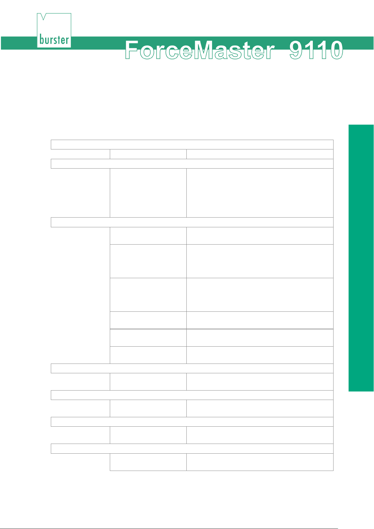
Reset PLC
This sub-menu item resets the PLC.
See program
This sub-menu item allows you to see the PLC
Edit program
Next STEP
Select this sub-menu item in order to edit the next
program step.
Entry condition
Select this sub-menu item in order to specify the
Entry command
Select this sub-menu item in order to specify the
Entry END
Select this sub-menu item in order to stop
Previous STEP
Select this sub-menu item in order to edit the
Delete program
Select this sub-menu item in order to delete the
Enable PLC
You can enable the PLC in this sub-menu. The
Enable I/O
Blog PLC + I/O
Activate this menu item in order to stop receiving
3.13 "PLC & IO" menu
This menu is only present on the ForceMaster 9110 with the step chain option. The step chain is a
very good way of automating small workstations economically.
See Section 3.17 Schrittkettensteuerung for more information.
You can make the following selections in the sub-menus:
program, but not to change it.
This lets you get a quick overview of the program.
By turning the knob, you can navigate through the
lines. Press the operating knob to return to the
main menu.
condition for the program step.
Entry parameter Select this sub-menu item in order to specify the
The standard error message signals are provided
You will find a list of possible conditions in Section
6.3.1 Liste möglicher Bedingungen.
command in the program step.
You will find a list of possible commands in
Section 6.3.2 Liste möglicher Befehle.
parameter for the program step.
processing the program step.
previous program step.
program entirely.
PLC executes the program.
at the outputs through this menu item.
signals at the outputs.
29 of 95
Page 30

"PLC & IO" menu
Reset PLC
1 Open the "PLC & I/O" menu.
2 Press the operating knob in order to select the "Reset PLC" menu item.
See program
1 Open the "PLC & I/O" menu.
2 Turn the operating knob until the "See program" menu item appears.
3 Press the operating knob in order to select the menu item.
4 Turn the operating knob in order to navigate through the lines of the menu.
5 Press the operating knob to return to the main menu.
Edit program
1 Open the "PLC & I/O" menu.
2 Turn the operating knob until the "Edit program" menu item appears.
3 Press the operating knob in order to select the menu item.
4 Turn the operating knob until the "Entry condition" menu item appears.
5 Press the operating knob in order to select the menu item.
6 Turn the operating knob in order to select the condition that you want.
7 Press the operating knob to confirm the condition.
8 Press the operating knob in order to select the "Entry command" menu item.
9 Turn the operating knob in order to select the command that you want.
10 Press the operating knob to confirm the command.
30 of 95
11 Press the operating knob in order to select the "Entry parameter" menu item.
12 Turn the operating knob in order to set the parameter that you want.
13 Press the operating knob in order to select the "Next STEP" menu item.
14 Repeat steps 2 to 13 until you have written the program through to the end.
15 If you want to correct an earlier step, turn the operating knob until "Previous STEP"
appears. Press the operating knob. Repeat this procedure until the step that needs
correcting appears.
16 Turn the operating knob until the "END entry" menu item appears.
17 Press the operating knob in order to select the menu item.
Page 31

Device concept
Delete program
1 Open the "PLC & I/O" menu.
2 Turn the operating knob until the "Delete program" menu item appears.
3 Press the operating knob in order to select the menu item.
4 Turn the operating knob until the "Yes" menu item appears.
5 Press the operating knob in order to select the menu item.
Enable PLC
1 Open the "PLC & I/O" menu.
2 Turn the operating knob until the "Enable PLC" menu item appears.
3 Press the operating knob in order to select the menu item.
Enable I/O
1 Open the "PLC & I/O" menu.
2 Turn the operating knob until the "Enable I/O" menu item appears.
3 Press the operating knob in order to select the menu item.
Blog PLC and I/O
1 Open the "PLC & I/O" menu.
2 Turn the operating knob until the "Blocking PLC + I/O" menu item appears.
3 Press the operating knob in order to select the menu item.
31 of 95
Page 32
"PLC & IO" menu
Condition
Meaning
Condition
Meaning
E1
Input 1 = 1
T1
Timer 1 elapsed
E2
Input 2 = 1
T2
Timer 2 elapsed
E3
Input 3 = 1
/T1
Timer 1 running
E4
Input 4 = 1
/T2
Timer 2 running
E5
Input 5 = 1
TDC
Top dead centre reached
E6
Input 6 = 1
/TDC
Top dead centre not reached
E7
Input 7 = 1
BDC
Bottom dead centre reached
E8
Input 8 = 1
/BDC
Bottom dead centre not reached
/E1
Input 1 = 0
OK
Part OK
/E2
Input 2 = 0
NOK
Part not OK
/E3
Input 3 = 0
<F1
Force smaller than force
Input 4 = 0
>F1
Force greater than force threshold
below
/E5
Input 5 = 0
<F2
Force smaller than force
Input 6 = 0
>F2
Force greater than force threshold
/E7
Input 7 = 0
DC0
Down counter = 0
/E8
Input 8 = 0
DCG
Down counter greater than 0
N1
Cam 1 = 1
TR
System triggered
N2
Cam 2 = 1
/TR
System not triggered
N3
Cam 3 = 1
N4
Cam 4 = 1
N5
Cam 5 = 1
N6
Cam 6 = 1
/N1
Cam 1 = 0
/N2
Cam 2 = 0
/N3
Cam 3 = 0
/N4
Cam 4 = 0
/N5
Cam 5 = 0
/N6
Cam 6 = 0
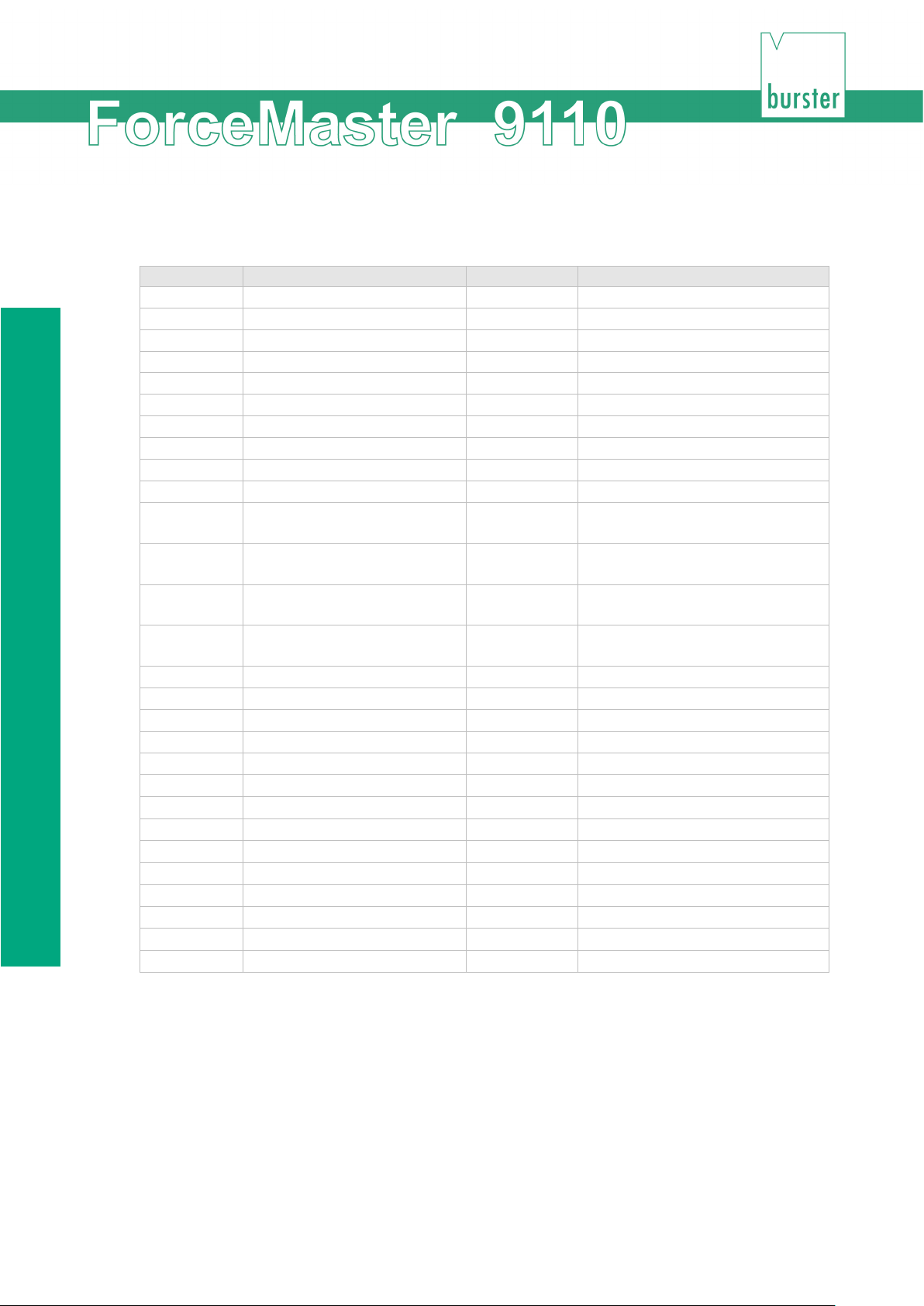
3.13.1 List of possible conditions
threshold below
/E4
threshold above
/E6
above
32 of 95
Page 33
Device concept
Command
Parameter
O1
Output 1
O2
Output 2
O3
Output 3
O4
Output 4
O5
Output 5
O6
Output 6
O7
Output 7
O8
Output 8
/O1
Reset output 1
/O2
Reset output 2
/O3
Reset output 3
/O4
Reset output 4
/O5
Reset output 5
/O6
Reset output 6
/O7
Reset output 7
/O8
Reset output 8
T1
Set timer 1 0.1 – 9.9 sec. (Input 1 = 0.1 sec)
T2
Set timer 2 0.1 – 9.9 sec.
/T1
Reset timer 1
/T2
Reset timer 2
JMP
Jump to target line
BE
Set beep
/BE
Reset beep
LO
Switch OK LED on
LN
Switch NOK LED on
/L
Switch LEDs off
CN+
NOK counter +1
CO+
OK counter +1
AE
Acknowledge error
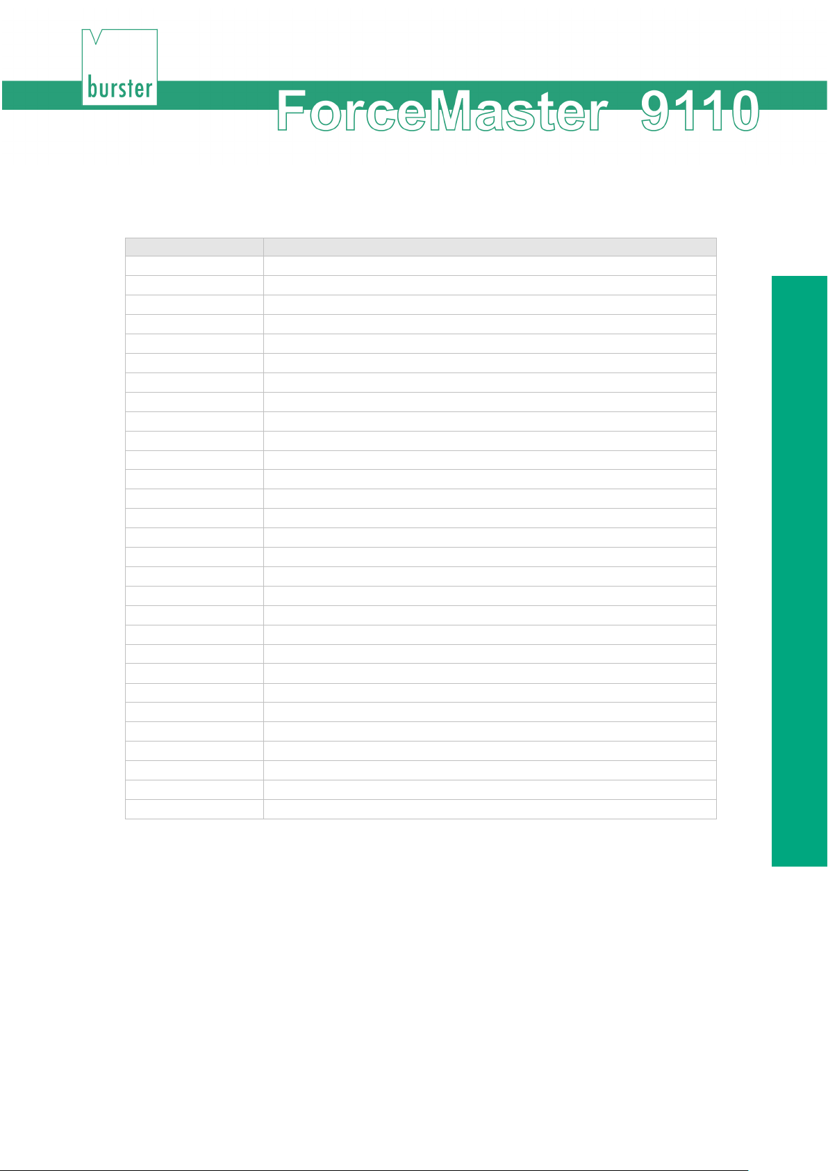
3.13.2 List of possible commands
3.14 "Cam" menu
This menu is only present on the ForceMaster 9110 with the step chain option.
The cams are an extension to the PLC. The PLC can query the electronic cams, and in that way
control automation procedures.
There is more information in Section 3.18, "Nockenschaltwerk".
33 of 95
Page 34
"Cam" menu
Next cam
Select this sub-menu item in order to edit the next
Cam end
Select this sub-menu item to set the end of the
Delete
You can make the following selections in the sub-menus:
Programming
cam.
Cam start Select this sub-menu item to set the beginning of
the cam.
cam.
Delete the complete setting with this sub-menu
item if you want to create an entirely new cam
program.
Programming cams
1 Open the "Cams" menu.
2 Press the operating knob in order to select the "Program" menu item.
3 Turn the operating knob until the "Cam start" menu item appears.
4 Press the operating knob in order to select the menu item.
5 Turn the operating knob in order to set the start value that you want.
6 Press the operating knob to confirm the value.
7 Press the operating knob in order to select the "End cam" menu item.
8 Turn the operating knob in order to set the end value that you want.
9 Press the operating knob to confirm the value.
10 Press the operating knob in order to select the "Next cam" menu item.
5 Repeat steps 3 to 10 until you have set all the cams that you want to.
Deleting cams
1 Open the "Cams" menu.
2 Turn the operating knob until the "Delete" menu item appears.
3 Press the operating knob in order to select the menu item.
4 Turn the operating knob until the "Yes" menu item appears.
6 Press the operating knob in order to select the menu item.
"CARD" menu.
34 of 95
Page 35

Device concept
3.15 Measuring and adjusting
The ForceMaster 9110 operates in two principal ways:
1) Measuring mode
2) Setup menu
The measuring mode is automatically active after switching on unless there is a MasterCard in the
card reader. In measuring mode, you can select different information windows by pressing the
operating knob.
The values set in the ForceMaster 9110 cannot be changed unless a MasterCard is inserted in
the device. You can only get to the settings menu if you have the appropriate authority by having
the MasterCard.
You get into measuring mode from the settings menu by pressing the operating knob when the
display is showing either "MENU start" or MENU". In that case, the ForceMaster 9110 changes
automatically into measuring mode after five seconds.
If measuring mode is left, and the MasterCard removed, the ForceMaster 9110 can no longer be
adjusted.
3.16 Force alarms
If auxiliary energy (compressed air or hydraulic power) are used for pressing, the ForceMaster
9110 can protect against excessive forces.
There are two force alarms for this purpose. Both force alarms set output 8, and have a reaction
time of about 1 millisecond. The occurrence of the alarm is indicated by an error message.
3.16.1 Force alarm 1
Force alarm 1 is effective from top dead centre of the press onwards until the ForceMaster 9110
detects the trigger. Once the trigger point has been reached, this alarm can no longer be
activated.
Force alarm 1 is therefore active when a part that is to be pressed is not positioned properly, as a
result of which the force shows spikes.
On a press using auxiliary energy, this alarm can be used to bring about an immediate halt or to
initiate a return stroke. This allows damage to the workpiece or the press to be prevented.
3.16.2 Force alarm 2
Force alarm 2 is always effective. It is useful if you want to protect your workpiece, tool or the
press itself.
On a press using auxiliary energy, this alarm can be used to bring about an immediate halt or to
initiate a return stroke. This allows damage to the workpiece, or the press to be prevented.
35 of 95
Page 36

Step chain controller (option)
3.17 Step chain controller (option)
The integrated step chain controller provides a good way of making even simple workstations
more productive.
The range of functions has been kept simple. The number of programming steps is limited to 60.
The step chain controller operates according to the step chain principle. If the condition at the
beginning of a line is satisfied, the command on that line is executed.
The step chain controller has 8 outputs, 7 inputs, and an emergency input. All the inputs can be
programmed with all the outputs. Internal signals, such as TDC, BDC, OK, NOK and others are
generated, and can be combined with other signals.
Possible conditions and commands will be found in Section 6.3 "PLC & IO“.
36 of 95
Page 37
Device concept
Cam start
Cam end
Function
20.2 mm
30.3 mm
Press movement downwards: cam activation at 20.2 mm
38.8 mm
-36.6 mm
Press movement downwards: cam activation at 38.8 mm
-10.1 mm
12.2 mm
Press movement upwards: cam activation at 10.1 mm
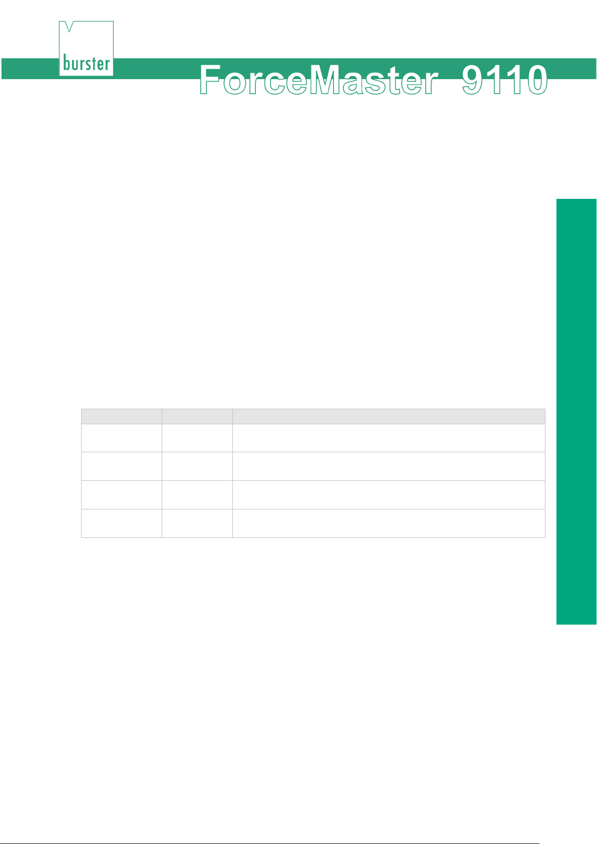
3.18 Cam switching mechanism
It is often helpful to add automated operations to a manual press.
Examples:
• When the press plunger moves down, the workpiece is fixed pneumatically.
• A welding pulse is triggered when the lowest point is reached.
• When the press plunger moves upwards, the workpiece is ejected
pneumatically.
Control procedures of this type can be implemented easily using the optional cam switching
mechanism.
Six freely programmable cams are available. Each of these cams is defined by a cam start and a
cam end. Control signals can be triggered by these cams. The cam signals can exclusively be
used through the step chain controller.
If the programmed value is positive, then the reaction occurs during the downwards movement of
the press. If the programmed value is negative, then the reaction occurs during the upwards
movement of the press.
Examples:
Press movement downwards: cam deactivation at 30.3 mm
-35.5 mm -16.6 mm Press movement upwards: cam activation at 35.5 mm
Press movement upwards: cam deactivation at 16.6 mm
Press movement upwards: cam deactivation at 36.6 mm
Press movement downwards: cam deactivation at 12.2 mm
If the electrical power supply to the ForceMaster 9110 is to be used for switching, pins 1 and 2
must be bridged together, as must pins 25 and 24. An input is activated through an electrical
contact from p 2 to the input pin.
The procedure for setting the cams will be found in Section 6.4 "Cams" menu“.
37 of 95
Page 38
Step chain controller (option)
Pin
Signal
Meaning
3
A1
OK 4 A2
Error
5
A3
Force
6
A4
Displacement
7
A5
Too high
10
A8
Alarm received
11
12
13
14
16
E8
Emergency off for International PLC operation
17
E7
Not evaluated by the ForceMaster 9110
18
E6
Not used
19
E5
Not used
20
E4
Not used
24
GND (E)
Common contact for all inputs
25
GND
Supply voltage
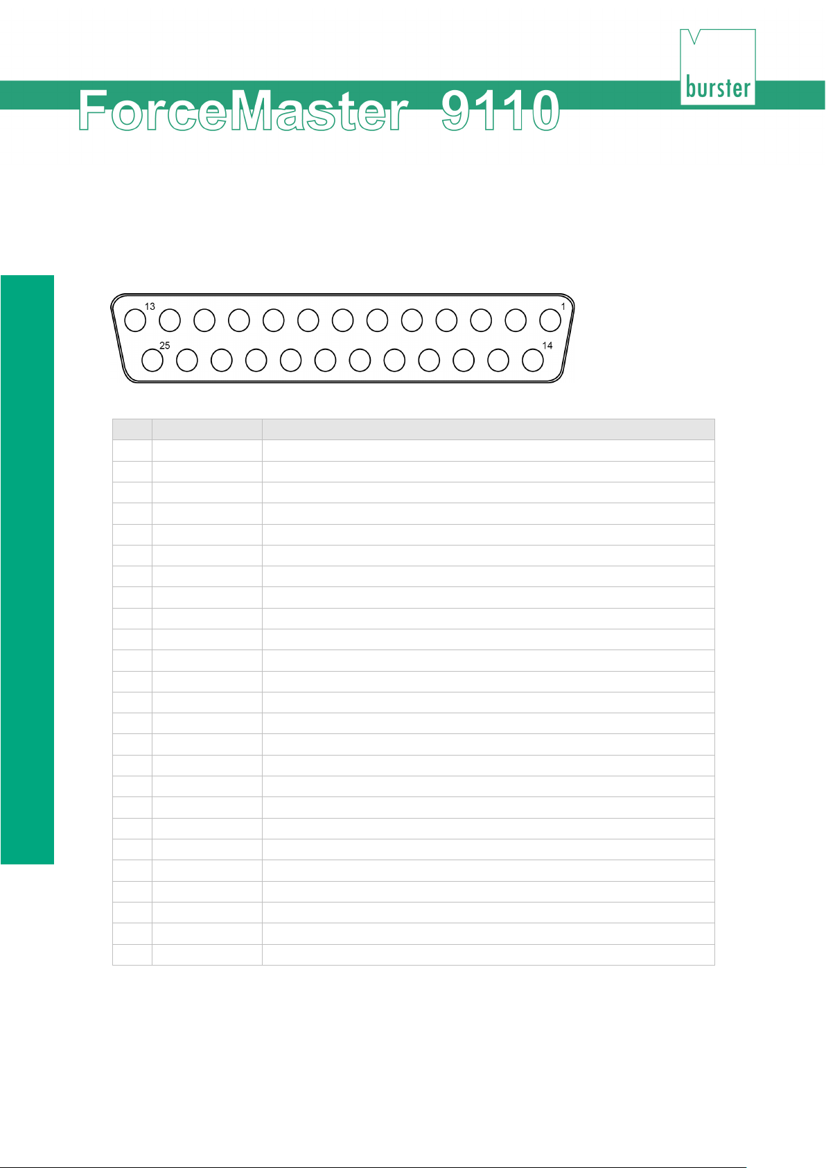
3.19 I/O interface
3.19.1 Connector pin assignments
1 U+ Supply voltage + 24 V
2 U+ (A) Common contact for all outputs U+
8 A6 Force in measuring window OK
9 A7 Ready to measure (blocking magnet)
15
21 E3 Not used
22 E2 Not used
23 E1 Error acknowledgement (100 ms pulse)
If the electrical power supply to the ForceMaster 9110 is to be used for external signals, pins 1
and 2 must be bridged together, as must pins 25 and 24.
The procedure for setting the cams will be found in Section 6.4 Fehler! Verweisquelle konnte
nicht gefunden werden..
38 of 95
Page 39
Device concept
A7
Ready for measurement
Signals
Meaning
A2 + A3
- Force too small (with normal
A2 + A4
- Force too small (with very small
not reached)
A2 + A4 + A5
End of measurement not reached
A1
Measurement OK
A6
Force between KSU and KSO (even
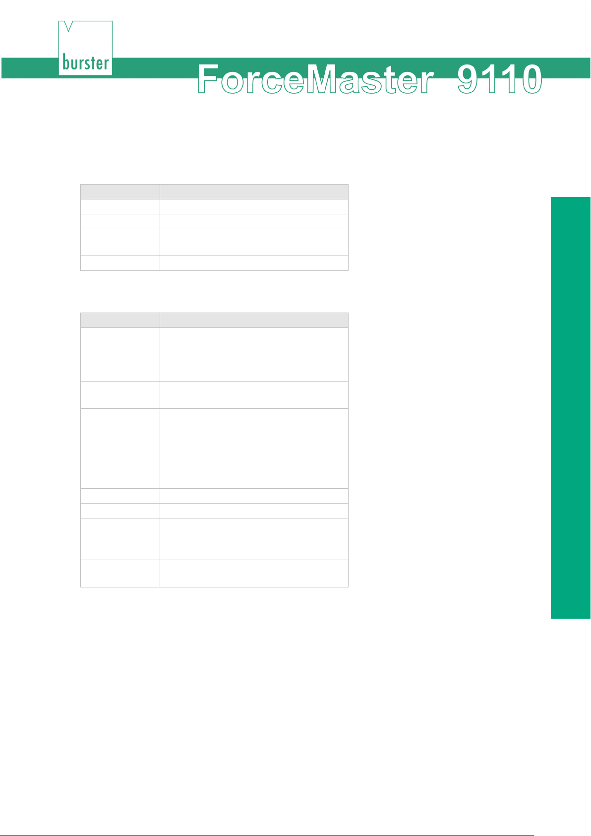
3.19.2 I/O signal combinations
"Force-displacement" measuring mode with gateways
Signals Meaning
A2 + A3 Force-displacement gateway error
A1 Measurement OK
A8 Force 1 or 2 has been exceeded (even
if measurement has not started)
"Force-displacement" measuring mode with force thresholds, or "Force-time"
displacement and threshold)
- BSU not reached
- BSO exceeded BE exceeded
A2 + A3 + A5 - Force too large with threshold
- Gateway violated
A7 Ready for measurement
A8 Force 1 or 2 has been exceeded (even
displacement and threshold)
- Peening displacement to small
- KSO exceeded
- Forced to small (start of measurement
when measurement has not started!)
if measurement has not started)
In addition to setting the outputs, the error messages are also displayed. Since the amount of
space on the display is limited, only one of the error messages available internally is displayed. As
a result, the same error message may be associated with a different pattern of set outputs.
Note
If one of the two alarm monitors is active, then output A8 is always reserved for
the status indication! This is true even when the step chain function is active, with
PLC+I/O blocked, or with an activated I/O function! The output A8 must not then
be used in the step chain function!
39 of 95
Page 40

Switching on procedure
3.20 Switching on procedure
Note
Once the ForceMaster 9110 has been switched on, it is ready for use after about 10 seconds.
If the sensors have been changed, the device recognizes this, and the message "Sensors have
been changed" appears. Perform an autoconfiguration if the sensors have been changed.
If the calibration interval of two years for one or more of the parts of the measuring system has
elapsed, the message "Load cell (or Displacement sensor or ForceMaster 9110) calibration
service” appears.
This is a reminder that a quality assurance systems such as the ForceMaster 9110 must be recalibrated regularly. Clear this message with the operating knob. It is only shown for your benefit,
and does not have any effect on the measuring function. This function can be deactivated.
If the ForceMaster 9110 still has an error saved from the last time it was operating, the
corresponding error message appears. This message cannot be cleared without a MasterCard. It
only appears if the error acknowledgement "with MasterCard and marker" is set.
Only change the sensors when the equipment is switched off.
Otherwise it cannot be guaranteed that the measured values are correct. The
sensors are only detected when switching on.
• The welcome text "HELLO" appears on the display.
• The ForceMaster 9110 carries out a self-test. It checks whether the sensors
from the last autoconfiguration are still connected.
• Information about the firmware version and the item number is displayed.
• The measurements of force and displacement appear. The device is ready to
use.
40 of 95
Page 41
Initial commissioning
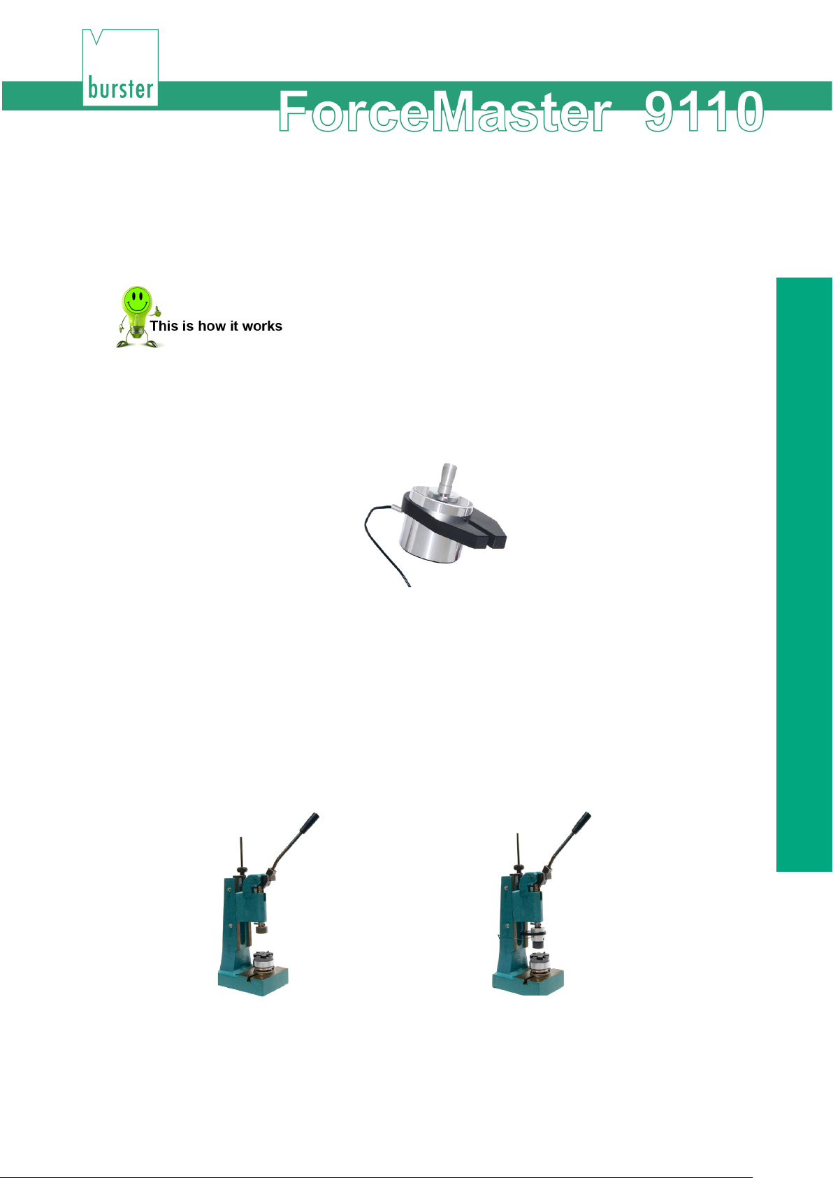
Push the press head upwards
Insert the sensor and the pressing tool
4. Initial commissioning
4.1 Fitting the load cell to the manual press
1 Push the supplied catch from the 5501-Z004 assembly kit from the peg
side, over the load cell.
7 Clamp the catch carefully (max. tightening torque 3 Nm) to the upper edge
of the load cell.
Mounting the catch on the load cell
2 If there is a pressing tool on the manual press, remove it.
3 Push the press head upwards by a distance equal to the height of the load
cell (depending on the measuring range).
4 Insert the load cell into the press plunger and fasten it with the grub screw
that is in the stamp.
8 Insert your pressing tool from underneath into the load cell, and fasten it
with the grub screw that is in the sensor. If there is a pressing tool on the
manual press, remove it.
41 of 95
Page 42
Fitting the load cell to the manual press
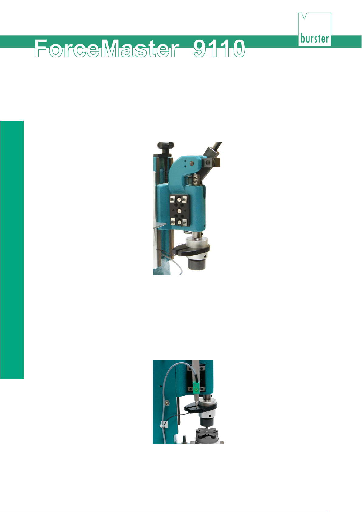
4.2 Fitting the displacement measurement system (DMS) to the manual press
1 Fit the adapter for the displacement sensor on the side of the press.
9 Use the 5501-Z004 adapter from the assembly kit supplied.
Adapter plate for displacement measurement system (DMS) on the
press
2 Push the displacement sensor with the probe tip downwards into the
adapter (typical application).
The probe tip must touch the catch that is already mounted on the load cell.
10 Push the displacement sensor downwards (the press is in the upper
position) until the displacement sensor's probe tip is firmly against its upper
stop (1-2 mm difference).
42 of 95
Displacement measurement system (DMS) in the upper position
Page 43
Initial commissioning
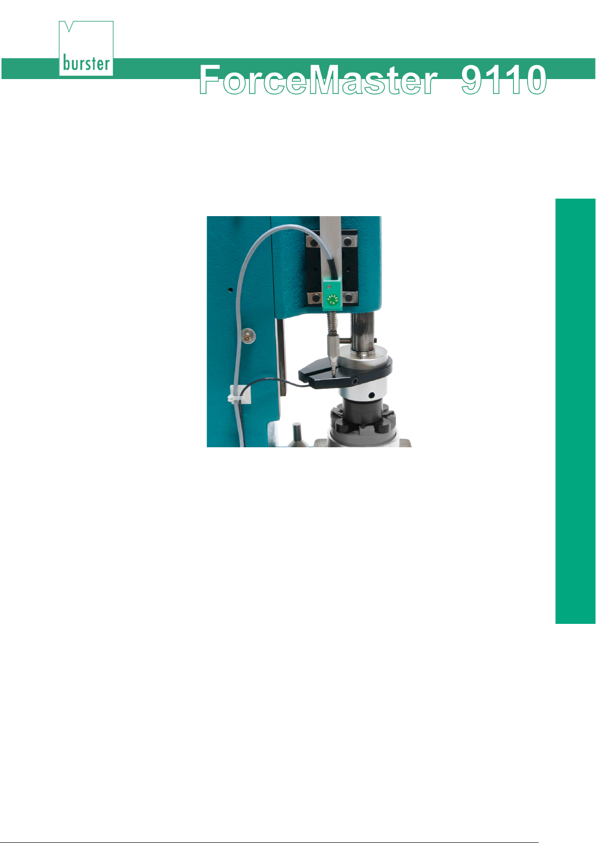
11 Check the lower press function (bottom dead centre BDC), by carefully
moving the press plunger downwards.
Voraussetzung: The displacement sensor must move freely, without
transverse force, and must not reach its lower stop at
BDC. It is necessary to make sure that the probe tip is
lying against the catch of the load cell.
Displacement measurement system (DMS) in the lower position
If a correction run is carried out, you will have to make some readjustment to the
displacement sensor. The aim is for the displacement sensor to be able to move
freely between the upper and lower positions of the press without reaching
either of its stops. Since the system deliberately provides a large number of
adjustment options (Moving the catch, displacement sensor and press head),
you will soon have found the correct position for the displacement sensor.
3 After any necessary readjustment/correction of the alignment has been
done, fasten finally all the relevant fitted parts (catch, displacement sensor,
press head if necessary) .
The sensors are now mounted on the manual press and are mechanically
adjusted for the parts that are to be pressed.
4 Connect the sensors to the ForceMaster 9110.
12 Switch the ForceMaster 9110 on.
43 of 95
Page 44
Fitting the load cell to the manual press
4.3 Setting up the measurement chain on the ForceMaster 9110
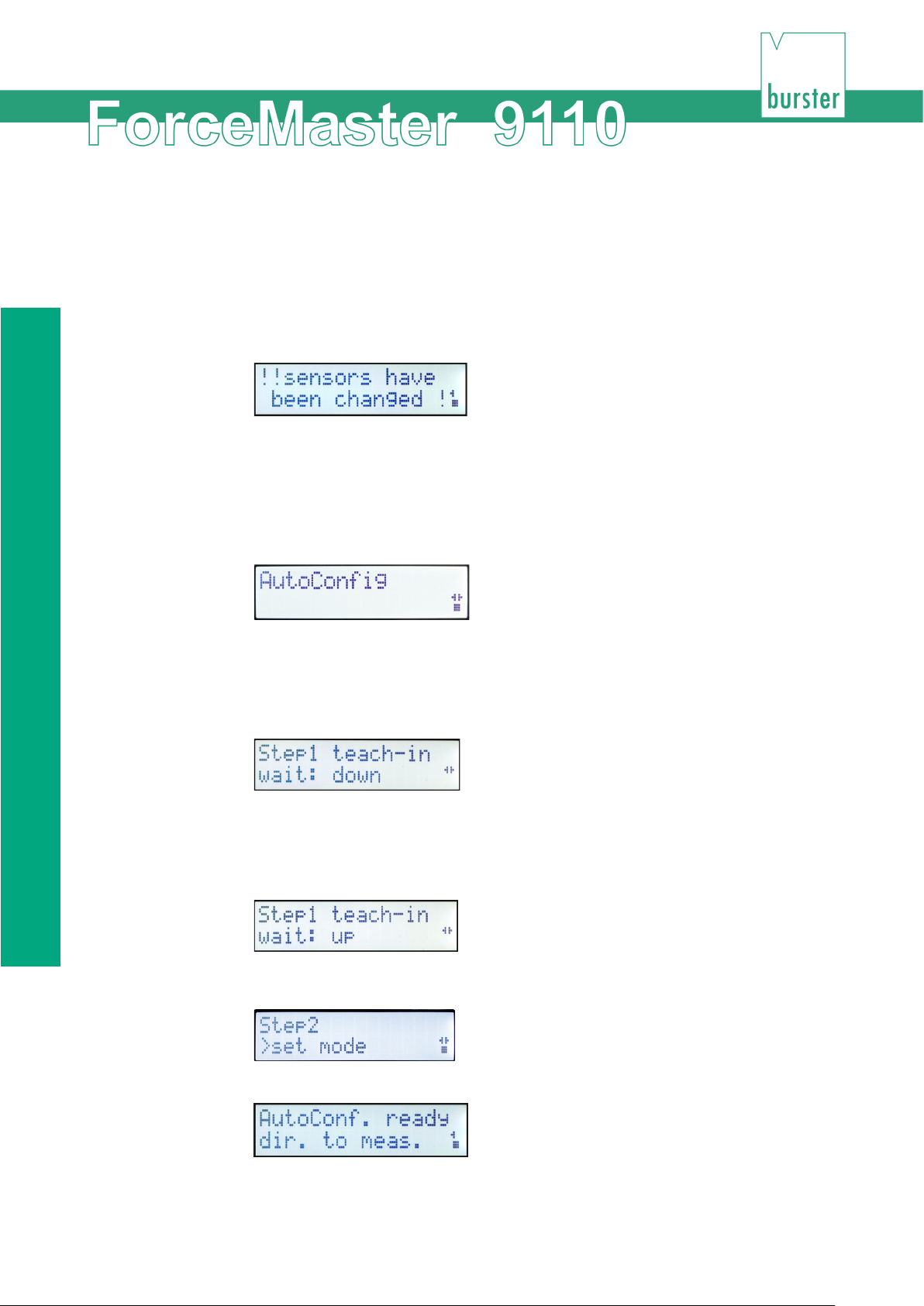
The message "sensors have been changed" is shown on the display after a self-test.
1 Press the operating knob to clear this message.
In order to train the measurement chain it is necessary to carry out an "autoconfig". As a result,
the ForceMaster 9110 automatically sets the evaluation elements for the part that is to be
pressed.
2 To carry out the autoconfig, insert the MasterCard into the card reader, and
turn the operating knob to the right until "AutoConfig" appears on the
display.
3 Push the operating knob in order to open the next sub-menu, "Step1 teach-
in“.
4 Press the operating knob again.
The display will show:
5 Carry out a pressing operation.
After you have pressed a part, the display will show "Step1 teach-in wait: up" before you move the
punch back to the top.
When the pressing operation is complete, the numeric display shows "Step2
>set mode“.
6 Turn the operating knob until you reach the following display.
The ForceMaster 9110 has saved the values it has learned, and is ready for measuring. You can
start production, with supervision.
44 of 95
Page 45

Initial commissioning
It may be necessary to correct the values learnt through the autoconfiguration. If necessary, these
can be manually adjusted – see Section 3.11.3.
45 of 95
Page 46
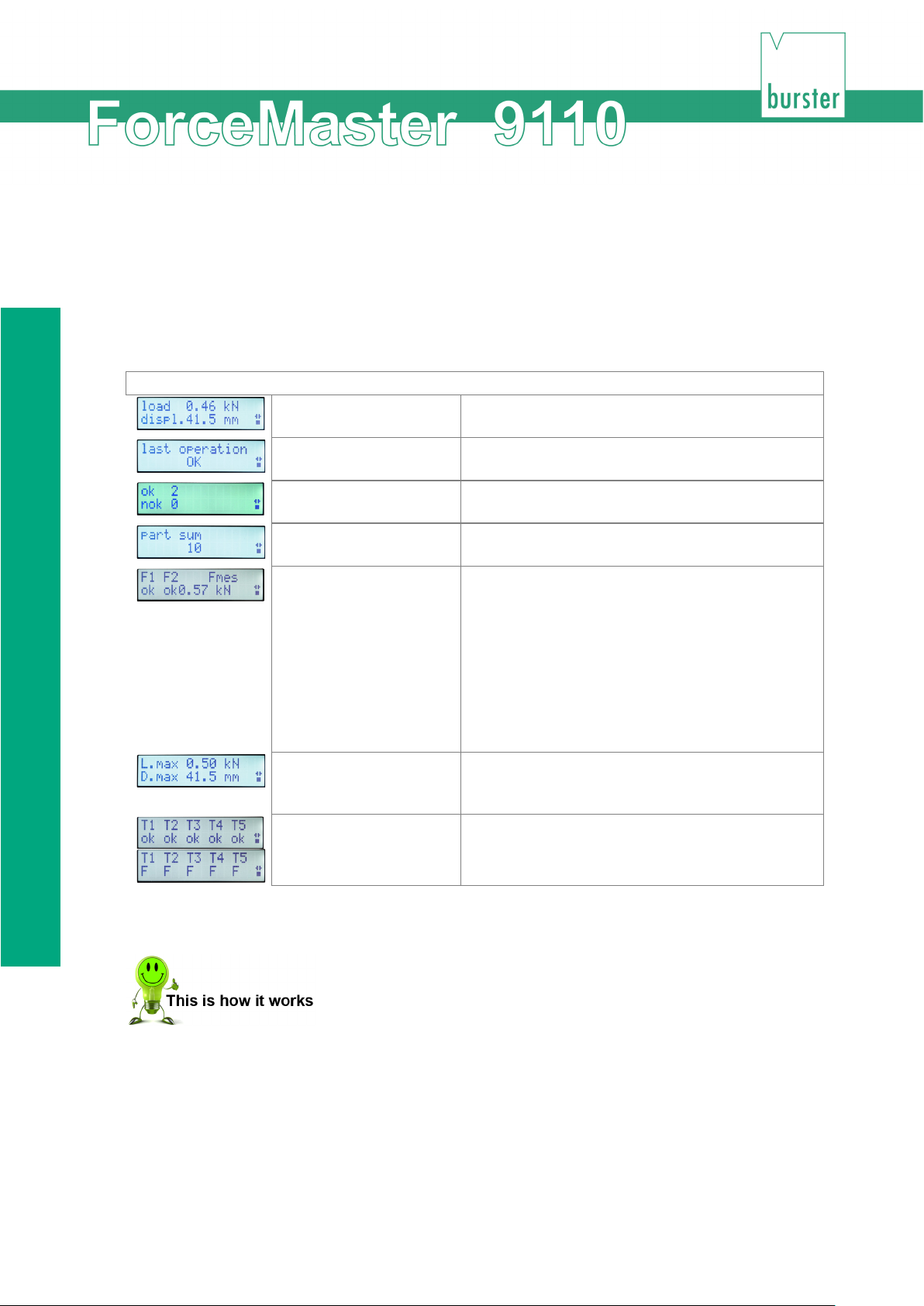
Fitting the load cell to the manual press
Current values
In this window you see the current values for force
displacement.
Ok parts, nok parts
In this window you can see how many operations
Parts total
In this window you see how many parts have
been checked altogether.
carried out.
Max. values
In this window you see the maximum force and
the last pressing operation.
T1 T2 T3 T4 T5
You see the evaluation of the gateways here, if
5. Measurement
In measuring mode you can choose between various information windows. Press the operating
knob to move from one window to the next.
After the "Max. values" window, the current values appear again.
You can choose between the following information windows:
Measuring mode
Last operation In this window you can see whether the last
F1, F2, Fmes F1: Status of force threshold 1
operation was OK or NOK.
were OK and how many were NOK.
Possible values are low or ok
F2: : Status of force threshold 2
Possible values are high or ok
high: force threshold was exceeded
low: force threshold was not reached
ok: evaluation OK
Fmes: the force with which the evaluation was
the maximum displacement that occurred during
Retrieving information in measuring mode
1 Drücken Sie den Bedienknopf im Messbetrieb so oft, bis die gewünschte
Information auf dem Display erscheint.
1 In measuring mode, press the operating knob as often is necessary for the
desired information to appear on the display.
46 of 95
activated.
Page 47

Measurement
In measuring mode, an error that occurs during the pressing operation is shown immediately as a
message on the display. You must acknowledge this error message (with or without MasterCard,
depending on the setting). After acknowledging the error the selected information window appears
again.
An attention signal sounds as soon as you produce a faulty part and (deliberately or accidentally)
do not acknowledge this procedure. Operating the press again immediately results in a further
error message.
In addition, the red lamp flashes in order to provide a further indication that a faulty part has been
produced. After acknowledging the error message, the red lamp continues to flash in order to
remind you that the last part that was produced was faulty.
47 of 95
Page 48
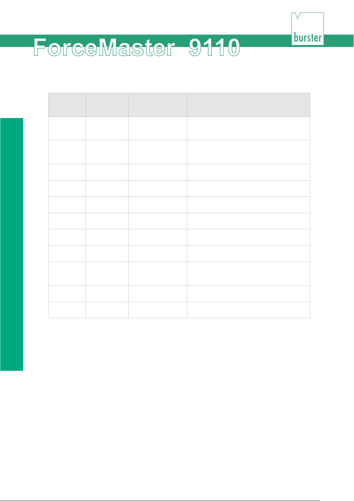
Fitting the load cell to the manual press
Internal
number
Displayed
Full text
Meaning
7
Pdisp too
Peening
The relative peening displacement was
8
Pdisp too
Peening
The relative peening displacement was
9
ESO
Thread in threshold
The thread in force was larger than
11
BE exceeded
Block end
The insertion displacement was larger than
13
BSU not
Block threshold
The blocking force has not reached the
15
Force too
Force too small
The force did not reach the lower threshold
16
ME not
End of
reached
The end of the measuring window was not
18
KSU violated
Force threshold
The force did not reach the lower threshold
Error messages and their meaning
fault
12 BSO
14 Force too
text
small
large
exceeded
exceeded
reached
large
small
reached
displacement too
small
displacement too
large
above exceeded
exceeded
Block threshold
above exceeded
below not reached
Force too large The force has exceeded the upper
measurement not
smaller than specified.
larger than specified.
specified.
the value for the block end.
The blocking force was larger than the block
threshold above.
block threshold below.
threshold in the measuring window.
in the measuring window.
reached.
below violated
19 Gateway
violated
Gateway violated Either the upper or the lower force limit was
in the measuring window.
violated in one of the 5 gateways.
48 of 95
Page 49
Configuring the ForceMaster 9110 settings
6. Configuring the ForceMaster 9110 settings
You can only reach the settings menu if the MasterCard is inserted in the card reader.
Opening one of the sub-menus
1 Insert the MasterCard into the card reader with the contacts pointing
towards the display.
2 Turn the operating knob until the sub-menu you want appears.
3 Press the operating knob in order to make settings in the sub-menu you
want.
The individual sub-menus are described in more detail further down in this document.
49 of 95
Page 50
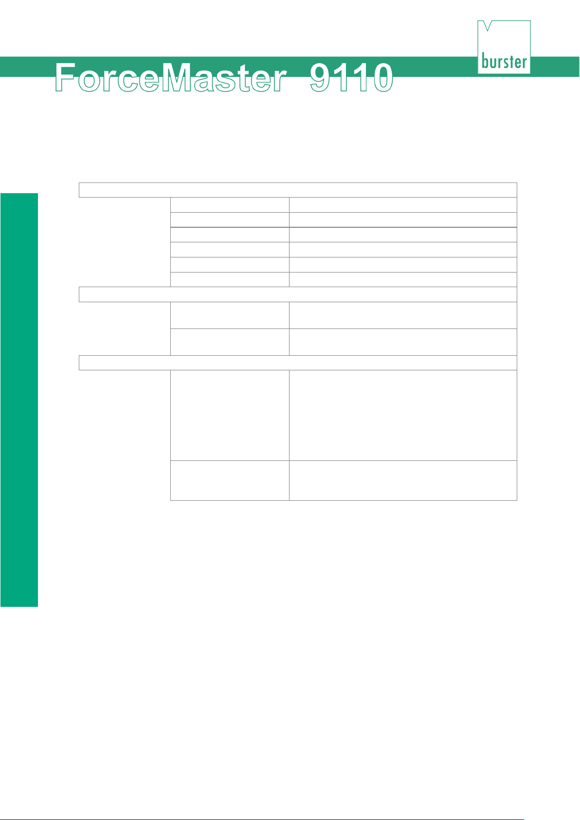
Fitting the load cell to the manual press
OK parts
Number of good parts
NOK parts
Number of bad parts
Down counter
Status of the down counter
Tot. strokes
Total number of strokes
delete
Parts counters
Sets the OK counter, the NOK counter and the
Down counter
Resets the down counter to the value specified
under sub-menu item "D-set".
set
Values 0 … 9999
Down c. text
Specifies the text that is to appear when the down
6.1 "Counter" menu
You can make the following settings in the Counter sub-menu:
display
Total parts Total of all parts
D-set Initial status of the down counter
total counter to zero.
Down counter Sets the initial value for the down counter.
The down counter allows you to have a freely
editable message shown on the display after the
number of working cycles that you specify.
When the message appears, it is necessary for it
to be confirmed at the press.
counter has counted down to zero.
Values 0 … 9 or Aa … Zz
Retrieving the value of a counter
1 Open the "Counters" menu.
2 Press the operating knob in order to select "Display".
2 Turn the operating knob until the value you want appears.
50 of 95
Page 51

Configuring the ForceMaster 9110 settings
Clearing the parts counter
1 Open the "Counters" menu.
2 Turn the operating knob until the "Clear" menu item appears.
3 Press the operating knob in order to select the menu item.
4 Press the operating knob in order to select "Parts count".
The message "Parts counter cleared" appears.
3 Press the operating knob to acknowledge the message.
Setting the down counter
1 Open the "Counters" menu.
2 Turn the operating knob until the "Set" menu item appears.
3 Press the operating knob in order to select the menu item.
4 Press the operating knob in order to select the "Down counter" menu item.
5 Turn the operating knob as long as necessary to see the number that you
want to set.
4 Press the operating knob to confirm the setting.
Entering text for the down counter
1 Open the "Counters" menu.
2 Turn the operating knob until the "Set" menu item appears.
3 Press the operating knob in order to select the menu item.
4 Turn the operating knob until the "Down counter text" menu item appears.
5 Enter the text. See Section 3.10.4, Text- und Zahleneingabe.
6 Turn the operating knob until "END input?" appears.
5 Press the operating knob to confirm the input.
51 of 95
Page 52
Fitting the load cell to the manual press
6.2 USB stick (option)
6.2.1 Operation with a USB stick
This section is only relevant if the interface for the USB stick is present.
A USB stick is not necessary to operate the ForceMaster 9110.
The USB stick inserted into the ForceMaster 9110 must be formatted.
If a USB stick is inserted, then the result of the last operation is written into the current job file
after every operation. If one is present, a lamp on the stick flashes in order to show that storage is
being carried out on the stick.
Caution
Do not switch the device off or withdraw the USB stick while storage is taking place or
If you have also selected curve logging with the stick inserted, then not only is the job file written,
but a graphic file is generated for every operation.
the stick's operating lamp is flashing.
This will result in loss of data and to problems storing data on the stick.
Note
The USB stick must be formatted as FAT. This permits a maximum storage capacity of 2
GB.
If a large quantity of data is already stored on the stick, the ForceMaster 9110 takes
longer to establish its data structure.
For fast working, the stick should contain is little data as possible. Existing data is
basically of no concern.
52 of 95
Page 53
Configuring the ForceMaster 9110 settings
USB status
USB module
"OK" means that a USB module is present, and is
this case 1 GB as an example).
"1014.1 MB free“
Indicates the available memory space (in this
"Folder 23_03_08"
Indicates the current folder where storage is
"JOB001.CSV"
Indicates the current job file to which data is being
"GRA011.CSV"
Indicates the next graphic file into which the next
Without stick:
OK
If this menu item is enabled, the ForceMaster
Without stick:
NOK
If this menu item is enabled, the ForceMaster
Curve -> stick
The most recent curve is stored on the stick under
6.2.2 "USB stick" menu
You can make the following settings in the "USB stick" menu:
working properly.
"NOK" means that either no USB module is
present, or that it is faulty.
USB stick "OK" means that the USB stick is present.
"Low" means that there is too little memory
capacity on the stick.
"NP" (not possible) means that the stick is faulty.
"No USB stick" means that no stick is inserted.
"Cap 1015.0 MB“
Indicates the storage capacity of the USB stick (in
case 1014.1 MB as an example).
presently taking place (in this case, folder
23_03_08 as an example).
written (in this case JOB001.CSV as an example).
pressing operation will be written (in this case
GRA011.CSV as an example).
9110 will also make measurements when no USB
stick is inserted, or if writing to the USB stick is not
possible.
9110 will not take measurements if it is not
possible to store the data on the stick. An error
message appears instead, and a warning tone is
sounded.
Work cannot continue until a USB stick on which it
is possible to write is inserted.
this menu item, so that a pressing operation can
be analyzed graphically.
53 of 95
Page 54
Fitting the load cell to the manual press
100 C -> stick
If this menu item is enabled, the following 100
100 C ->
STOP
If this menu item is enabled, the recording of 100 curves
All C -> stick
If this menu item is enabled, the following operations are
a great deal of space on the stick.
All C ->
operations are stored on the stick as a curve file.
Recording will stop after these 100 operations.
This is intended for product start-up, in order to record
this critical phase graphically.
is interrupted.
This menu item inactivates the previous one.
stored on the stick as a curve file.
This function is useful if graphical evaluations of critical
pressing operations on high-value parts are to be
carried out over a long period
Note that the ForceMaster 9110 is not able to measure
during the recording time. The graphic files also take up
STOP
If this menu item is enabled, the recording of all the
curves is interrupted.
This menu item inactivates the previous one.
Retrieving information from the USB status
1 Open the "USB stick" menu.
2 Press the operating knob in order to select "USB status".
6 Turn the operating knob until the information you want appears.
54 of 95
Page 55

Configuring the ForceMaster 9110 settings
Setting that measurements are also possible without a USB stick
1 Open the "USB stick" menu.
2 Turn the operating knob until the "Without stick: OK" menu item appears.
3 Press the operating knob in order to select the menu item.
Setting that measurements are only possible with a USB stick
1 Open the "USB stick" menu.
2 Turn the operating knob until the "Without stick: NOK" menu item appears.
3 Press the operating knob in order to select the menu item.
Storing the last measurement curve on the stick
1 Open the "USB stick" menu.
2 Turn the operating knob until the "Curve -> stick" menu item appears.
3 Press the operating knob in order to select the menu item.
Storing the next 100 measurement curves on the stick
1 Open the "USB stick" menu.
2 Turn the operating knob until the "100 C -> stick" menu item appears.
3 Press the operating knob in order to select the menu item.
Interrupting storage of the next 100 measurement curves on the stick
1 Open the "USB stick" menu.
2 Turn the operating knob until the "100 C -> STOP" menu item appears.
3 Press the operating knob in order to select the menu item.
Storing all measurement curves on the stick
1 Open the "USB stick" menu.
2 Turn the operating knob until the "All C -> stick" menu item appears.
7 Press the operating knob in order to select the menu item.
55 of 95
Page 56

Fitting the load cell to the manual press
Interrupting storage of all measurement curves on the stick
1 Open the "USB stick" menu.
2 Turn the operating knob until the "All C -> STOP" menu item appears.
8 Press the operating knob in order to select the menu item.
56 of 95
Page 57
Configuring the ForceMaster 9110 settings
Text in the data store
Meaning
PART.NO
Part number
ORDER.NO
Order number
265 1 0
Recording time[1], IO marker[2], error number[3]
52 1000
Sensor displacement max., sensor force max.
7 2 0
Measuring mode[4], blocking mode[5], thread in force
37.91 39.52 362 542
Block start, block end, block threshold below, block
30.67 213
Feet-in force end, upper thread in force threshold
32.28 50.9 157.6
2. Gateway position, gateway min., gateway max.
33.89 99.1 205.9
3. Gateway position, gateway min., gateway max.
35.50 140.8 247.5
4. Gateway position, gateway min., gateway max.
37.11 187.5 294.2
5. Gateway position, gateway min., gateway max.
29.02 32.3
Displacement value, force value
29.08 35.5
Displacement value, force value
29.16 38.4
Displacement value, force value
29.26 41.1
Displacement value, force value
29.36 41.6
Displacement value, force value
29.66 48.0
Displacement value, force value
29.63 51.4
Displacement value, force value
29.68 48.5
Displacement value, force value
29.64 48.2
Displacement value, force value
Etc. etc.
Displacement value, force value
6.2.3 Data storage example
15:36:27 11_02_10 10334455 9.014 Time, date, Snr.FM, Vers.SW. FM
Order data
ORDER.REF Order reference
CUSTOMER Customer name
Limits
mode[6]
30.67 38.72 213 320 Measurement start, measurement end, force threshold
below, force threshold above
threshold above
37.91 39.52 Peening displacement min., peening displacement max.
15.63 Trigger point displacement
29.86 0.0 106.7 1. Gateway position, gateway min., gateway max.
Curve data
28.89 28.9 Displacement value, force value
29.50 45.8 Displacement value, force value
57 of 95
Page 58
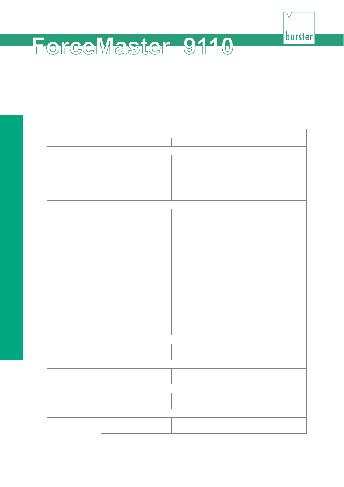
"PLC & IO" menu
Reset PLC
This sub-menu item resets the PLC.
See program
Edit program
Next STEP
Select this sub-menu item in order to edit the next
Entry command
Select this sub-menu item in order to specify the
Entry parameter
Select this sub-menu item in order to specify the
Previous STEP
Select this sub-menu item in order to edit the
Delete program
Enable PLC
You can enable the PLC in this sub-menu. The
Enable I/O
The standard error message signals are provided
at the outputs through this menu item.
Blog PLC + I/O
Activate this menu item in order to stop receiving
6.3 "PLC & IO" menu
This menu is only present on the ForceMaster 9110 with the step chain option. The step chain is a
very good way of automating small workstations economically.
See Section 3.17 Schrittkettensteuerung for more information.
You can make the following selections in the sub-menus:
This sub-menu item allows you to see the PLC
program, but not to change it.
This lets you get a quick overview of the program.
By turning the knob, you can navigate through the
lines. Press the operating knob to return to the
main menu.
program step.
Entry condition Select this sub-menu item in order to specify the
condition for the program step.
You will find a list of possible conditions in Section
6.3.1 Liste möglicher Bedingungen.
command in the program step.
You will find a list of possible commands in
Section 6.3.2 Liste möglicher Befehle.
parameter for the program step.
Entry END Select this sub-menu item in order to stop
processing the program step.
previous program step.
Select this sub-menu item in order to delete the
program entirely.
PLC executes the program.
58 of 95
signals at the outputs.
Page 59

Configuring the ForceMaster 9110 settings
Reset PLC
1 Open the "PLC & I/O" menu.
2 Press the operating knob in order to select the "Reset PLC" menu item.
See program
1 Open the "PLC & I/O" menu.
2 Turn the operating knob until the "See program" menu item appears.
3 Press the operating knob in order to select the menu item.
4 Turn the operating knob in order to navigate through the lines of the menu.
5 Press the operating knob to return to the main menu.
Edit program
1 Open the "PLC & I/O" menu.
2 Turn the operating knob until the "Edit program" menu item appears.
3 Press the operating knob in order to select the menu item.
4 Turn the operating knob until the "Entry condition" menu item appears.
5 Press the operating knob in order to select the menu item.
6 Turn the operating knob in order to select the condition that you want.
7 Press the operating knob to confirm the condition.
8 Press the operating knob in order to select the "Entry command" menu item.
9 Turn the operating knob in order to select the command that you want.
10 Press the operating knob to confirm the command.
11 Press the operating knob in order to select the "Entry parameter" menu item.
12 Turn the operating knob in order to set the parameter that you want.
13 Press the operating knob in order to select the "Next STEP" menu item.
14 Repeat steps 2 to 13 until you have written the program through to the end.
15 If you want to correct an earlier step, turn the operating knob until "Previous STEP"
appears. Press the operating knob. Repeat this procedure until the step that needs
correcting appears.
16 Turn the operating knob until the "END entry" menu item appears.
59 of 95
Page 60

"PLC & IO" menu
17 Press the operating knob in order to select the menu item.
Delete program
1 Open the "PLC & I/O" menu.
2 Turn the operating knob until the "Delete program" menu item appears.
3 Press the operating knob in order to select the menu item.
4 Turn the operating knob until the "Yes" menu item appears.
5 Press the operating knob in order to select the menu item.
Enable PLC
1 Open the "PLC & I/O" menu.
2 Turn the operating knob until the "Enable PLC" menu item appears.
3 Press the operating knob in order to select the menu item.
Enable I/O
1 Open the "PLC & I/O" menu.
2 Turn the operating knob until the "Enable I/O" menu item appears.
3 Press the operating knob in order to select the menu item.
Blog PLC and I/O
1 Open the "PLC & I/O" menu.
2 Turn the operating knob until the "Blocking PLC + I/O" menu item appears.
3 Press the operating knob in order to select the menu item.
60 of 95
Page 61
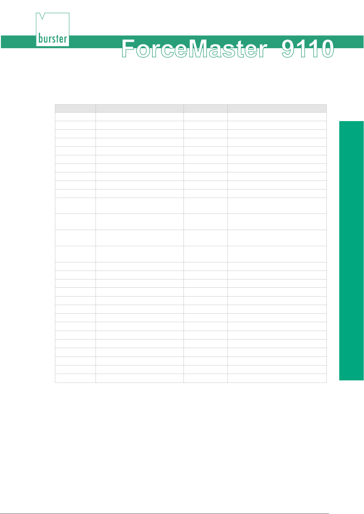
Configuring the ForceMaster 9110 settings
Condition
Meaning
Condition
Meaning
E1
Input 1 = 1
T1
Timer 1 elapsed
E2
Input 2 = 1
T2
Timer 2 elapsed
E3
Input 3 = 1
/T1
Timer 1 running
E4
Input 4 = 1
/T2
Timer 2 running
E5
Input 5 = 1
TDC
Top dead centre reached
E6
Input 6 = 1
/TDC
Top dead centre not reached
E7
Input 7 = 1
BDC
Bottom dead centre reached
E8
Input 8 = 1
/BDC
Bottom dead centre not reached
/E1
Input 1 = 0
OK
Part OK
/E2
Input 2 = 0
NOK
Part not OK
/E3
Input 3 = 0
<F1
Force smaller than force
Input 4 = 0
>F1
Force greater than force threshold
/E5
Input 5 = 0
<F2
Force smaller than force
/E6
Input 6 = 0
>F2
Force greater than force threshold
/E7
Input 7 = 0
DC0
Down counter = 0
/E8
Input 8 = 0
DCG
Down counter greater than 0
N1
Cam 1 = 1
TR
System triggered
N2
Cam 2 = 1
/TR
System not triggered
N3
Cam 3 = 1
N4
Cam 4 = 1
N5
Cam 5 = 1
N6
Cam 6 = 1
/N1
Cam 1 = 0
/N2
Cam 2 = 0
/N3
Cam 3 = 0
/N4
Cam 4 = 0
/N5
Cam 5 = 0
/N6
Cam 6 = 0
6.3.1 List of possible conditions
threshold below
/E4
below
threshold above
above
61 of 95
Page 62
"Cam" menu
Command
Parameter
O1
Output 1
O2
Output 2
O3
Output 3
O4
Output 4
O5
Output 5
O6
Output 6
O7
Output 7
O8
Output 8
/O1
Reset output 1
/O2
Reset output 2
/O3
Reset output 3
/O4
Reset output 4
/O5
Reset output 5
/O6
Reset output 6
/O7
Reset output 7
/O8
Reset output 8
T1
Set timer 1 0.1 – 9.9 sec. (Input 1 = 0.1 sec)
T2
Set timer 2 0.1 – 9.9 sec.
/T1
Reset timer 1
/T2
Reset timer 2
JMP
Jump to target line
BE
Set beep
/BE
Reset beep
LO
Switch OK LED on
LN
Switch NOK LED on
/L
Switch LEDs off
CN+
NOK counter +1
CO+
OK counter +1
AE
Acknowledge error
6.3.2 List of possible commands
6.4 "Cam" menu
This menu is only present on the ForceMaster 9110 with the step chain option.
The cams are an extension to the PLC. The PLC can query the electronic cams, and in that way
control automation procedures.
There is more information in Section 3.18 „Nockenschaltwerk“.
62 of 95
Page 63
Configuring the ForceMaster 9110 settings
Programming
Cam start
Select this sub-menu item to set the beginning of
Cam end
Select this sub-menu item to set the end of the
cam.
Delete
Delete the complete setting with this sub-menu
You can make the following selections in the sub-menus:
Next cam Select this sub-menu item in order to edit the next
cam.
the cam.
item if you want to create an entirely new cam
program.
Programming cams
1 Open the "Cams" menu.
2 Press the operating knob in order to select the "Program" menu item.
3 Turn the operating knob until the "Cam start" menu item appears.
4 Press the operating knob in order to select the menu item.
5 Turn the operating knob in order to set the start value that you want.
6 Press the operating knob to confirm the value.
7 Press the operating knob in order to select the "End cam" menu item.
8 Turn the operating knob in order to set the end value that you want.
9 Press the operating knob to confirm the value.
10 Press the operating knob in order to select the "Next cam" menu item.
11 Repeat steps 3 to 10 until you have set all the cams that you want to.
Deleting cams
1 Open the "Cams" menu.
2 Turn the operating knob until the "Delete" menu item appears.
3 Press the operating knob in order to select the menu item.
4 Turn the operating knob until the "Yes" menu item appears.
5 Press the operating knob in order to select the menu item.
63 of 95
Page 64
"Cam" menu
ToolCard
You read a tool card with this sub-menu item.
PLCCard
You read a PLC card with this sub-menu item.
Write
ToolCard
Through this sub-menu item, you save the current
PLCCard
Through this sub-menu item you save the current
Tool card direct
no
A MasterCard is required when loading a new
yes
A MasterCard is not required when loading a new
6.5 "CARD" menu
You can make the following selections in the sub-menus:
Read
The data saved on this card is then used for the
settings in the ForceMaster 9110.
The data saved on this card is then used in the
ForceMaster 9110 as the PLC program. At the
same time the cam data saved on this card is
written to the device memory.
settings of the ForceMaster 9110 with respect to
present data onto a tool card.
You can label the card, and can include it with the
order documentation.
PLC program and the cam settings onto a PLC
card.
You can label the card, and can include it with the
order documentation.
program from the ToolCard.
program from the ToolCard.
Insert a ToolCard into the card reader, and turn
the operating knob to the right until you reach the
Read ToolCard menu item. You can now read the
ToolCard, and are taken automatically back to the
measurement menu.
64 of 95
Page 65

Configuring the ForceMaster 9110 settings
Reading the ToolCard
1 Open the "CARD" menu.
2 Press the operating knob in order to select the "Read" menu item.
3 Take the MasterCard out of the card reader, and insert the ToolCard that
you want to read.
4 Press the operating knob in order to select the "Tool C" menu item. The
message "CARD read" appears.
5 Press the operating knob to acknowledge the message.
Writing to the ToolCard
1 Open the "CARD" menu.
2 Turn the operating knob until the "Write" menu item appears.
3 Press the operating knob in order to select the menu item.
4 Take the MasterCard out of the card reader, and insert the ToolCard onto
which you want to write the tool data.
5 Press the operating knob in order to select the "Tool C" menu item. The
message "CARD written" appears.
6 Press the operating knob to acknowledge the message.
Reading a PLCCard
1 Open the "CARD" menu.
2 Press the operating knob in order to select the "Read" menu item.
3 Take the MasterCard out of the card reader, and insert the PLCCard that
you want to read.
4 Turn the operating knob until the "PLCCard" menu item appears.
5 Press the operating knob in order to select the menu item. The message
"CARD read" appears.
6 Press the operating knob to acknowledge the message.
65 of 95
Page 66

"Cam" menu
Writing to the PLCCard
1 Open the "CARD" menu.
2 Turn the operating knob until the "Write" menu item appears.
3 Press the operating knob in order to select the menu item.
4 Take the MasterCard out of the card reader, and insert the PLCCard onto
which you want to write the current PLC program.
5 Turn the operating knob until the "PLCCard" menu item appears.
6 Press the operating knob in order to select the menu item. The message
"CARD written" appears.
7 Press the operating knob to acknowledge the message.
Enable reading a ToolCard for workers without MasterCards
1 Open the "CARD" menu.
2 Turn the operating knob until the "ToolCard direct" menu item appears.
3 Press the operating knob in order to select the menu item.
4 Turn the operating knob until the "Yes" menu item appears.
5 Press the operating knob in order to select the menu item.
Block reading a ToolCard for workers without MasterCards
1 Open the "CARD" menu.
2 Turn the operating knob until the "ToolCard direct" menu item appears.
3 Press the operating knob in order to select the "No" menu item.
66 of 95
Page 67
Configuring the ForceMaster 9110 settings
TR FO
TR DS
FO Alarm 1
FO Alarm 1
You can move the threshold for the force alarm 2
6.6 "Manual settings"" menu.
You can make the following selections in the sub-menus:
You can set the trigger point for the value of the
force through this sub-menu item.
You should, however, have enough experience of
monitoring the pressing force to make this setting
sensibly.
You can set the trigger point for the value of the
displacement through this sub-menu item.
You should, however, have enough experience of
monitoring the pressing force to make this setting
sensibly.
You can move the threshold for the force alarm 1
through this sub-menu item.
through this sub-menu item.
Setting the value of the force for the trigger point
1 Open the "Manual settings" menu.
2 Press the operating knob in order to select the "TR FO" menu item.
3 Turn the operating knob as long as necessary to see the value that you
want to set.
4 Press the operating knob to confirm the setting.
Setting the value of the displacement for the trigger point
1 Open the "Manual settings" menu.
2 Turn the operating knob until the "TR DS" menu item appears.
3 Press the operating knob in order to select the menu item.
4 Turn the operating knob as long as necessary to see the value that you
want to set.
5 Press the operating knob to confirm the setting..
67 of 95
Page 68

"Cam" menu
Setting force alarm 1
1 Open the "Manual settings" menu.
2 Turn the operating knob until the "FO alarm 1" menu item appears.
3 Press the operating knob in order to select the menu item.
4 Turn the operating knob as long as necessary to see the value that you
want to set.
2 Press the operating knob to confirm the setting.
Setting force alarm 2
1 Open the "Manual settings" menu.
2 Turn the operating knob until the "FO alarm 1" menu item appears.
3 Press the operating knob in order to select the menu item.
4 Turn the operating knob as long as necessary to see the value that you
want to set.
3 Press the operating knob to confirm the setting.
68 of 95
Page 69
Configuring the ForceMaster 9110 settings
Error signal
series of beeps
A repeating error signal remains active until
single hoot of the horn
series of horn hoots
single siren sound
series of siren sounds
Error signal volume
quiet
medium
loud
Error acknowledgement
standard
In this sub-menu you can choose how the
with MasterCard
Errors can only be acknowledged with a
with MasterCard and
Errors can only be acknowledged with the
Beep off
Beep at BF
A warning tone for the operative when he presses
Beep when
A warning tone for the operative when he
6.7 "Error signals" menu
Warning
Only use the highest volume level in a working environment where hearing protection
is obligatory. There is a risk of hearing damage.
You can make the following selections in the sub-menus:
single beep In this sub-menu you can choose the sound with
which the device reacts to a pressing error.
acknowledged.
very loud
pressing error is acknowledged. Error
acknowledgement without MasterCard
MasterCard.
MasterCard. The error message remains active
until switched on again.
at blocking force. When the desired blocking force
is reached, a short signal tone sounds to confirm
the correct force.
peening
marker
The warning tone is switched off.
performs a peening operation. When the desired
peening displacement is reached, a short signal
tone sounds to confirm correct peening.
69 of 95
Page 70

"Cam" menu
The large number of error signals makes it possible to detect quickly the device that is signaling
an error in an environment with several ForceMaster 9110s.
Setting the type of error signal
1 Open the "Error signal" menu.
2 Press the operating knob in order to select the "Error signal" menu item.
3 Turn the operating knob as long as necessary to see the type of error signal
that you want to set.
4 Press the operating knob to confirm your selection.
Setting the volume of the error signal
1 Open the "Error signal" menu.
2 Turn the operating knob until the "Error signal volume" menu item appears.
3 Press the operating knob in order to select the menu item.
4 Turn the operating knob as long as necessary to see the volume that you
want to set.
5 Press the operating knob to confirm your selection.
Setting the type of error acknowledgement
1 Open the "Error signal" menu.
2 Turn the operating knob until the "Error acknowledgement" menu item
appears.
3 Press the operating knob in order to select the menu item.
4 Turn the operating knob as long as necessary to see the type of
acknowledgement that you want to set.
5 Press the operating knob to confirm your selection.
Setting the warning tone when the blocking force is reached
1 Open the "Error signal" menu.
2 Turn the operating knob until the "Beep at BF" menu item appears.
3 Press the operating knob in order to select the menu item.
Setting the warning tone when the peening displacement is reached
1 Open the "Error signal" menu.
2 Turn the operating knob until the "Beep when peening" menu item appears.
3 Press the operating knob in order to select the menu item.
70 of 95
Page 71

Configuring the ForceMaster 9110 settings
Switching off the warning tone
1 Open the "Error signal" menu.
2 Turn the operating knob until the "Beep off" menu item appears.
3 Press the operating knob in order to select the menu item.
71 of 95
Page 72
"Order data" menu
ItemNo
You can enter the text for the item number here.
You can enter the text for the item designation
You can enter the text for the order number here.
Customer
You can enter the text for the customer's name
6.8 "Order data" menu
This data appears in the printout, and is written into the USB stick. It is also available in
measuring mode.
You can make the following selections in the sub-menus:
The text appears on printouts, and in the Excel
table of the job memory.
ItemDes
here. The text appears on printouts, and in the
Excel table of the job memory.
OrderNo
The text appears on printouts, and in the Excel
table of the job memory.
here. The text appears on printouts, and in the
Excel table of the job memory.
Entering the item number
1 Open the "Order data" menu.
2 Press the operating knob in order to select the "ItemNo" menu item.
4 Enter the item number. See Section 3.10.4, Text- und Zahleneingabe.
72 of 95
Page 73

Configuring the ForceMaster 9110 settings
Entering the item designation
1 Open the "Order data" menu.
2 Turn the operating knob until the "ItemDes" menu item appears.
3 Press the operating knob in order to select the menu item.
4 Enter the item number. See Section 3.10.4, Fehler! Verweisquelle konnte
nicht gefunden werden..
Entering the order number
1 Open the "Order data" menu.
2 Turn the operating knob until the "OrderNo" menu item appears.
3 Press the operating knob in order to select the menu item.
4 Enter the item number. See Section 3.10.4, Fehler! Verweisquelle konnte
nicht gefunden werden..
Entering the customer name
1 Open the "Order data" menu.
2 Turn the operating knob until the "Customer" menu item appears.
3 Press the operating knob in order to select the menu item.
5 Enter the item number. See Section 3.10.4, Fehler! Verweisquelle konnte
nicht gefunden werden.“.
73 of 95
Page 74
"Order data" menu
Parts per hour
Parts per minute
Time for ten parts
Time for a hundred parts
6.9 "Statistics" menu
This menu is purely an information window. The time for the statistical information begins when
the setting menu is closed, and stops when the measurement menu is closed.
You can retrieve the following information in this menu:
Statistics
Time per part
Retrieving statistical information
1 Open the "Statistics" menu.
6 Turn the operating knob until the information you want appears.
74 of 95
Page 75
Configuring the ForceMaster 9110 settings
Special
normal
Select this menu item in order to return to the
FS. Autoconfig
When you start an autoconfiguration, the
RS232 <-> USB
RS232
Select this menu item in order to switch from the
Cal. message
off
Select this menu item in order to switch the
on
Select this menu item in order to switch the
and the sensor on.
6.10 "Manual and internal settings" menu
You can make the following selections in the sub-menus:
displacement
inverse The ForceMaster 9110 expects a rising value from
the displacement sensor when the press is
moving in the direction of the workpiece
(downwards). Our displacement sensors are
shipped such that when the press is moving
downwards, the sensing pin springs out of the
sensor housing.
If you have chosen to mount the displacement
sensor in such a way that it runs in the opposite
direction, you can invert the display direction in
this menu through the "inverse" menu item.
standard display direction.
auto Select this menu item in order to have the display
direction depended automatically.
ForceMaster 9110 takes the force as a trigger in
order to detect when the pressing process starts.
This standard figure is for this force to be 5% of
the sensor's rated value.
If you want a larger or smaller triggering force for
some particular application, you can set it in this
menu.
USB interface to the RS232 interface.
USB Select this menu item in order to switch from the
RS232 interface to the USB interface.
calibration message about the ForceMaster 9110
and the sensor off.
calibration message about the ForceMaster 9110
75 of 95
Page 76
"Order data" menu
Display format
Displacement
Select this menu item in order to choose the unit
Force
Select this menu item in order to choose the unit
pound-f, Kp, pdl.
UTK
Train
Train the UTK sensor to the position of the bottom
Adjustment
Adjust the UTK sensor at the press, so that the
Standard settings
This sub-menu item sets the ForceMaster 9110
in which displacement is measured. Possibilities:
millimeters, inches, free
in which the force is measured. Possibilities: N,
dead centre of the press.
measuring range covers the full range through
which the press travels.
two standard values.
This is useful when settings have been made in
the various sub-menus that are inappropriate.
After the standard settings have been restored,
the ForceMaster 9110 is again in the state in
which it was shipped.
Setting the displacement measurement for the sensing pin in compression
1 Open the "Internal settings" menu.
2 Press the operating knob in order to select the "Special displacement" menu item.
3 Turn the operating knob until the "Inverse" menu item appears.
7 Press the operating knob in order to select the menu item.
Setting the displacement measurement for the sensing pin in extension
1 Press the operating knob in order to select the "Special displacement"
menu item.
8 Press the operating knob in order to select the "Normal" menu item.
76 of 95
Page 77

Configuring the ForceMaster 9110 settings
Triggerkraft einstellen
1 Open the "Internal settings" menu.
2 Turn the operating knob until the "FS autoconfig" menu item appears.
3 Press the operating knob in order to select the menu item.
4 Press the operating knob in order to select the "Force level" menu item.
5 Turn the operating knob in order to set the value that you want.
6 Press the operating knob to confirm your setting..
Selecting the RS232 interface
1 Open the "Internal settings" menu.
2 Turn the operating knob until the "RS232 <-> USB" menu item appears.
3 Press the operating knob in order to select the "RS232" menu item.
Selecting the USB interface
1 Open the "Internal settings" menu.
2 Turn the operating knob until the "RS232 <-> USB" menu item appears.
3 Press the operating knob in order to select the menu item.
4 Turn the operating knob until the "USB" menu item appears.
5 Press the operating knob in order to select the menu item.
Switching the calibration message off
1 Open the "Internal settings" menu.
2 Turn the operating knob until the "Standard settings" menu item appears.
3 Turn the operating knob until the "CAL message" menu item appears.
4 Turn the operating knob until the "Yes" menu item appears.
5 Press the operating knob in order to select the menu item.
Switching the calibration message on
1 Open the "Internal settings" menu.
2 Turn the operating knob until the "Standard settings" menu item appears.
3 Turn the operating knob until the "CAL message" menu item appears.
4 Turn the operating knob until the "No" menu item appears.
5 Press the operating knob in order to select the menu item.
77 of 95
Page 78

"Order data" menu
Changing the displacement unit
1 Open the "Internal settings" menu.
2 Turn the operating knob until the "Display format" menu item appears.
3 Press the operating knob in order to select the menu item.
4 Turn the operating knob until the "Displacement" menu item appears.
5 Press the operating knob in order to select the menu item.
6 Turn the operating knob until the unit you want appears.
9 Press the operating knob in order to select the menu item.
Changing the force unit
1 Open the "Internal settings" menu.
2 Turn the operating knob until the "Display format" menu item appears.
3 Press the operating knob in order to select the menu item.
4 Turn the operating knob until the "Force" menu item appears.
5 Press the operating knob in order to select the menu item.
6 Turn the operating knob until the unit you want appears.
7 Press the operating knob in order to select the menu item.
Training the UTK
1 Open the "Internal settings" menu.
2 Turn the operating knob until the "Train the UTK" menu item appears.
3 Press the operating knob in order to select the menu item.
4 Bring the press, with the UTK sensor fitted, to the bottom dead centre position.
5 Press the operating knob in order to conclude the procedure. The UTK sensor is now
tared to a value of 182°.
78 of 95
Page 79

Configuring the ForceMaster 9110 settings
Adjusting the UTK
1 Open the "Internal settings" menu.
2 Turn the operating knob until the "Adjust the UTK" menu item appears.
3 Press the operating knob in order to select the menu item.
4 Bring the UTK sensor with the shaft to a position at which the entire transit path of the
press is continuously displayed.
5 Press the operating knob in order to conclude the procedure.
6 Execute the "Train the UTK" menu item.
Setting to standard settings
1 Open the "Internal settings" menu.
2 Turn the operating knob until the "Standard settings" menu item appears.
3 Press the operating knob in order to select the menu item.
4 Turn the operating knob until the "Yes" menu item appears.
5 Press the operating knob in order to select the menu item.
79 of 95
Page 80
"Order data" menu
The date is needed by the ForceMaster 9110 for
order to set it.
Time
The time is needed by the ForceMaster 9110 for
6.11 "Date & time" menu
You can make the following selections in the sub-menus:
Date
printouts, for the job memory, and for monitoring
the calibration intervals. Choose this menu item in
printouts and for the job memory. Choose this
menu item in order to set it.
Setting the date
1 Open the "Date & time" menu.
2 Press the operating knob in order to select the "Date" menu item.
3 Turn the operating knob in order to set the day.
4 Press the operating knob to confirm the value.
5 Repeat steps 3 and 4 for the month and for the year.
Setting the time
1 Open the "Date & time" menu.
2 Turn the operating knob until the "Time" menu item appears.
3 Press the operating knob in order to select the menu item.
4 Turn the operating knob in order to set the hours.
5 Press the operating knob to confirm the value.
6 Repeat steps 3 and 5 for the minutes.
80 of 95
Page 81
Configuring the ForceMaster 9110 settings
Status
Firmware version
Software version
Version date
Language
German
English
Italian
Hungarian
6.12 "Status" menu
This menu is purely an information window.
You can retrieve the following information in this menu:
C
Version time
1 Select the "Status" menu.
2 Turn the operating knob until the information you want appears.
6.13 "Languages" menu
Select this menu item in order to change the language settings.
French
Polish
1 Select the "Languages" menu.
2 Turn the operating knob as long as necessary to see the language that you
want to set.
3 Press the operating knob to confirm the set language.
81 of 95
Page 82
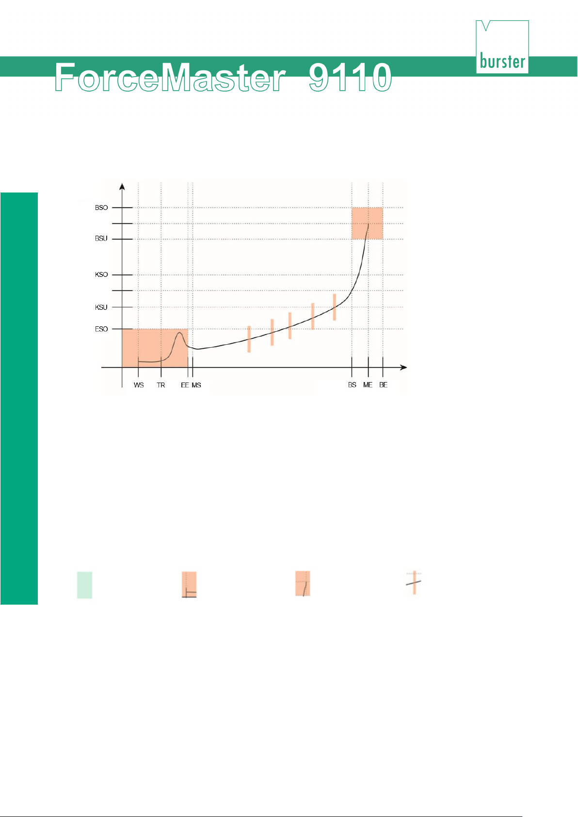
"Languages" menu
7. Force-displacement curves
Example of a pressing curve: The thread in region is represented as a red rectangle at the start of the
curve, and the blocking region as a red square at its end. The red bars symbolize the
gateways.
Abbreviations:
WS = displacement start TR = trigger
MS = measurement start ME = measurement end
KSU = force threshold below KSO = force threshold above
BS = block start BE = block end
BSU = block threshold below BSO = block threshold above
EE = end thread in ESO = thread in threshold above
Key:
Region Thread in window Block window Gateway
82 of 95
Page 83
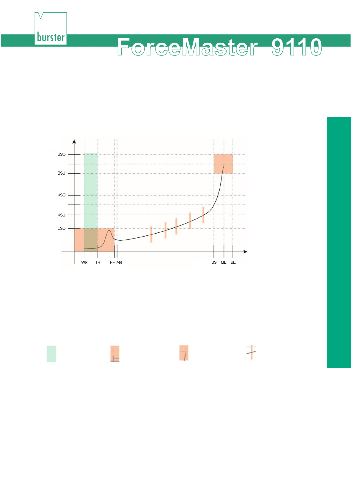
Force-displacement curves
Region 1
The press moves in the direction of the workpiece, without any force being developed. It is not
necessary to monitor the force in this region.
If the ForceMaster 9110 is being used in automatic presses, the Alarm force 1 can be used for
collision monitoring. (See Section 3.16 Kraft-Alarme).
Abbreviations:
WS = displacement start TR = trigger
MS = measurement start ME = measurement end
KSU = force threshold below KSO = force threshold above
BS = block start BE = block end
BSU = block threshold below BSO = block threshold above
EE = end thread in ESO = thread in threshold above
Key:
Region Thread in window Block window Gateway
83 of 95
Page 84
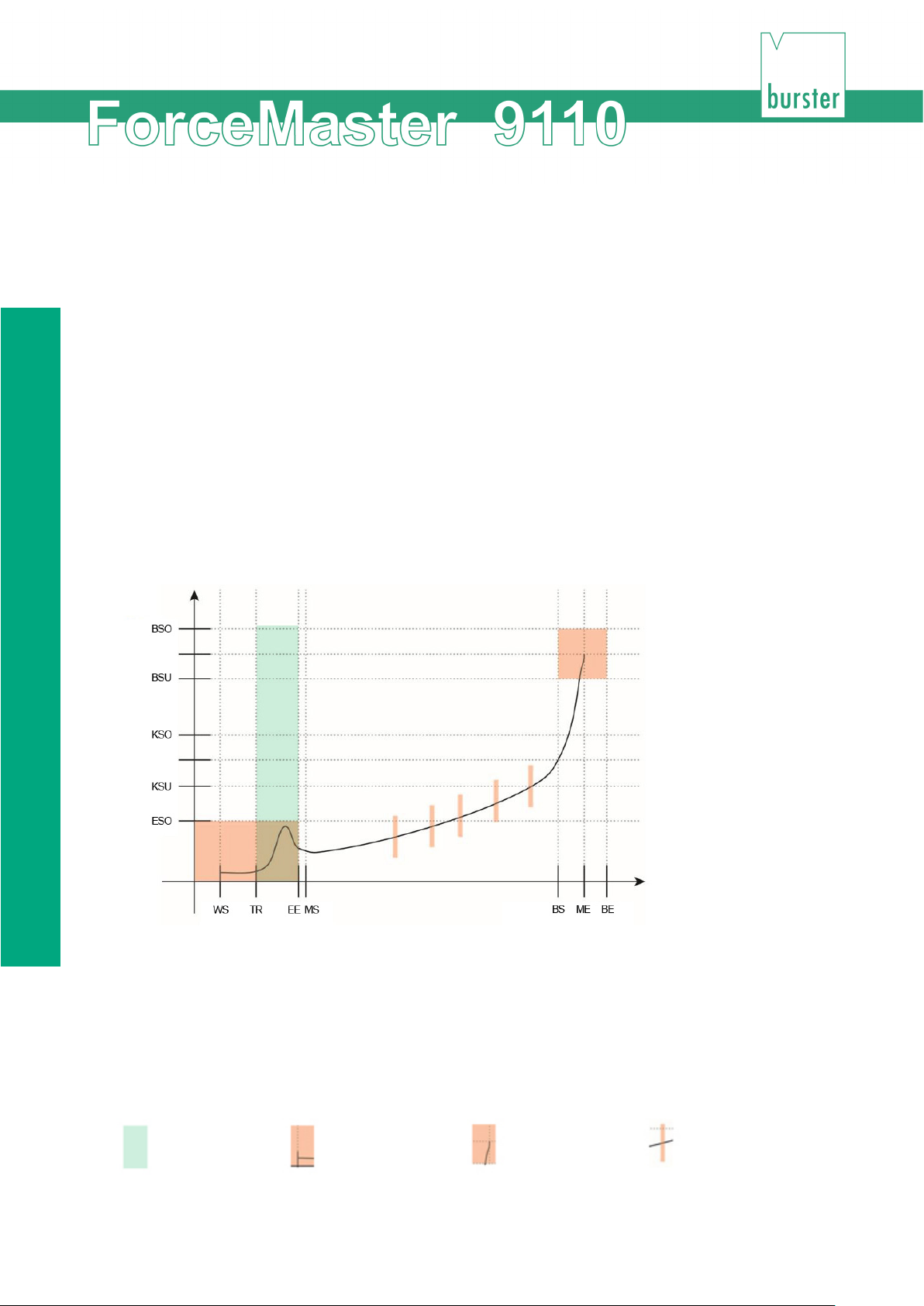
"Languages" menu
Region 2
The press meets the workpiece. This is a critical moment. In many cases an increased force
occurs here, since the part that is to be pressed in must be fed into the lower part of the
workpiece. That is why we refer to this force as the thread in force. It is sometimes useful to
monitor the thread in force. There are also pressing-in processes that do not give rise to a thread
in force.
A thread in force occurs when
• the part that is to be pressed in cannot be fed cleanly into the lower part
• there are sharp edges or burrs on both parts
• play in the pressing tool makes an exact pressing position difficult.
The thread in force has two monitoring parameters:
• force threshold above (KSO); the thread in force must not exceed this
threshold
• displacement start (EE), where monitoring of the thread in force ends.
Abbreviations:
WS = displacement start TR = trigger
MS = measurement start ME = measurement end
KSU = force threshold below KSO = force threshold above
BS = block start BE = block end
BSU = block threshold below BSO = block threshold above
EE = end thread in ESO = thread in threshold above
Key:
Region Thread in window Block window Gateway
84 of 95
Page 85

Force-displacement curves
Region 3
The thread in operation is complete. The force will rise, since the frictional forces of the parts
being pressed gets greater and greater. The force can vary both upwards and downwards. This is
a result of surface roughness and the effects of lubricating media such as cooling agent from the
machining, or even skin grease from touching the parts. Generally speaking, pressing operations
in region 3 are rarely closely reproducible, although similar in trend.
Two types of monitoring are available for the actual pressing region: two force thresholds or five
force gateways. (See Section 7 Kraft-Weg-Kurven).
• Force thresholds
The pressing region itself is monitored for two force thresholds.
The force threshold below (KSU) must be exceeded, since otherwise the
pressing force is too small and the parts could come apart again.
The force threshold above (KSO) must not be exceeded, as otherwise the
workpiece will be damaged.
• Force gateways
Gateways are force tolerance ranges that depend on displacement. The force
must not be above or below this gateway at defined displacements for a good
part. They are arranged at five displacement positions. The force profile must
pass through these gateways. Each gateway is defined by three parameters the position of the gateway on the displacement axis, the lower gateway point
Monitoring using force thresholds can be set up quickly, and is suitable for most operations. Force
gateways are more complicated to set up.
You can choose freely between the force threshold and gateway modes.
on the force axis and the upper gateway point on the force axis.
Even complicated force curves can be monitored since each gateway can be
defined freely.
85 of 95
Page 86
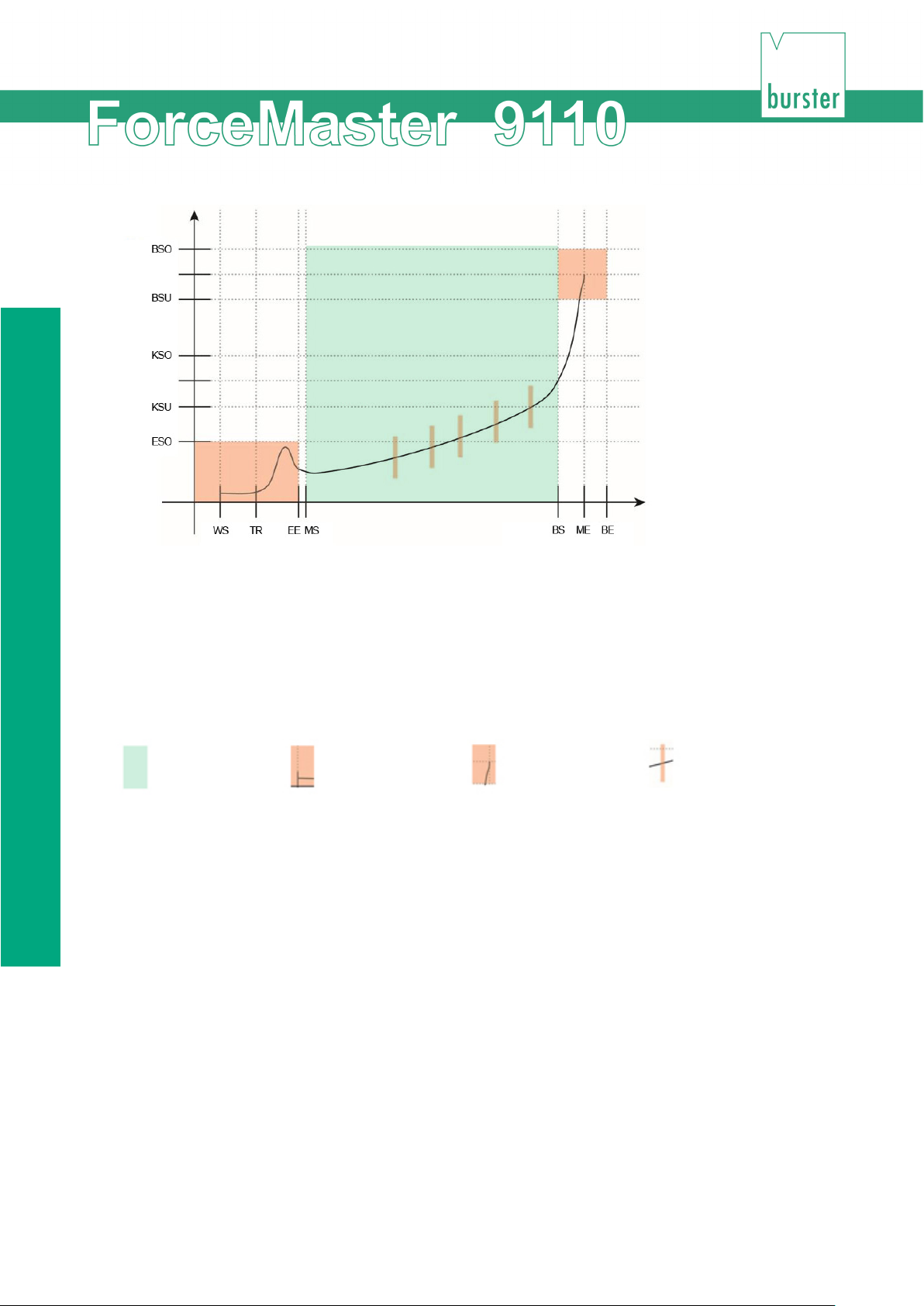
"Languages" menu
Abbreviations:
WS = displacement start TR = trigger
MS = measurement start ME = measurement end
KSU = force threshold below KSO = force threshold above
BS = block start BE = block end
BSU = block threshold below BSO = block threshold above
EE = end thread in ESO = thread in threshold above
Key:
Region Thread in window Block window Gateway
Region 4
The pressing operation has been completed. However, if the part that is to be pressed in is to
come against an internal stop (e.g. in a blind hole), then the part cannot be pressed in any further.
The part comes up against a block, which is why we call this force the blocking force. There are
reasons for monitoring this blocking region. These reasons will be considered more closely below.
The blocking force occurs when
1) the part being pressed in is pressed against a block (a floor)
2) the tool runs against a hard stop which limits the pressing position.
Blocking force does not occur when a hard stop on the press limits the pressing displacement. In
this case, monitoring the blocking force does not work.
Monitoring parameters for case 1:
The block threshold below (BSU) must be exceeded in order to make sure that the part is firmly
seated. The block threshold above (BSO) must not be exceeded, as otherwise the workpiece will
be damaged.
The block threshold below (BSU) must be reached. This is where blocking force monitoring starts.
86 of 95
Page 87
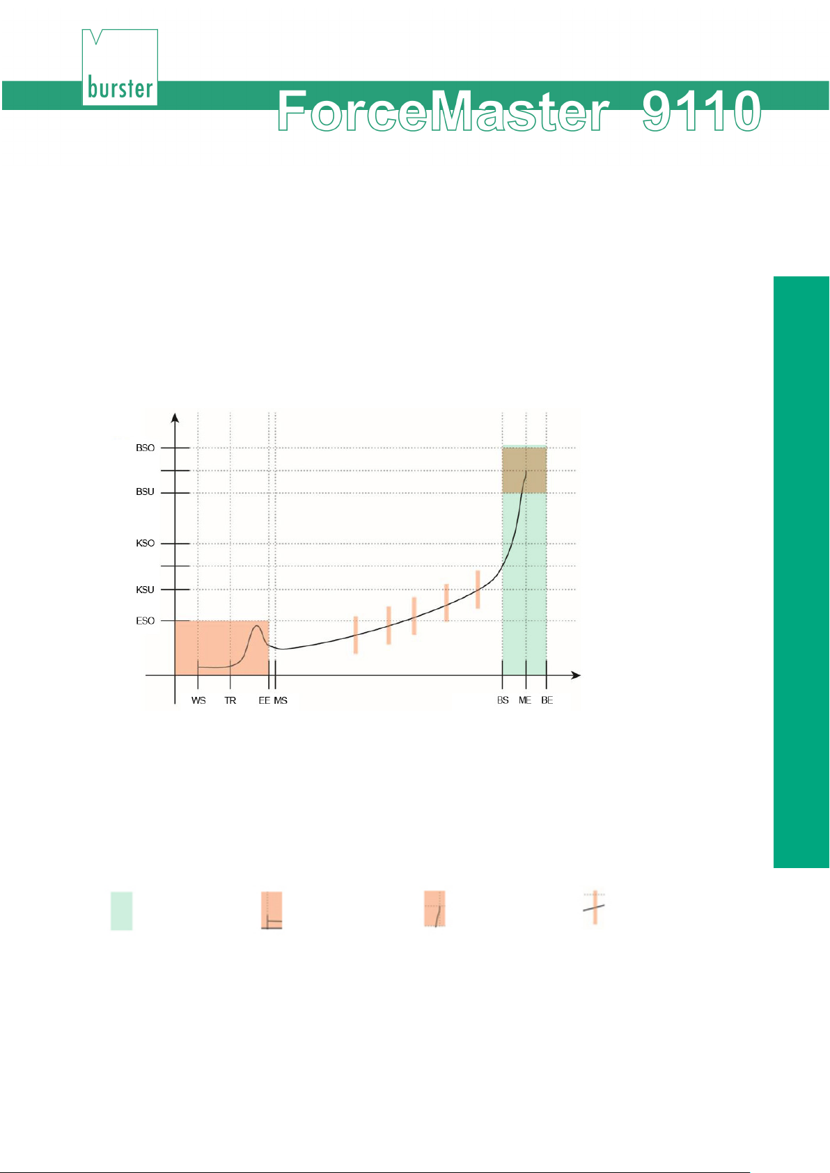
Force-displacement curves
The block threshold above (BSO) must not be exceeded, since otherwise manufacturing
tolerances will be violated.
Monitoring parameters for case 2:
In this case there are no force thresholds, since the tool finishes the insertion displacement. The
displacement is, however, must be monitored, in order to detect exceeding the manufacturing
tolerances.
The block threshold below (BSU) must be reached.
The block threshold above (BSO) must not be exceeded, since otherwise manufacturing
tolerances will be violated.
Abbreviations:
WS = displacement start TR = trigger
MS = measurement start ME = measurement end
KSU = force threshold below KSO = force threshold above
BS = block start BE = block end
BSU = block threshold below BSO = block threshold above
EE = end thread in ESO = thread in threshold above
Key:
Region Thread in window Block window Gateway
Region 5
Peening is a special case. A fastening effect is generated in peening operations through the
deformation of material. Peening operations usually involve a short displacement. It is useful here
to monitor the peening displacement and to check that a minimum peening force is achieved.
A force threshold above must not be exceeded, since otherwise there is a risk that the workpiece
may be damaged or destroyed.
87 of 95
Page 88
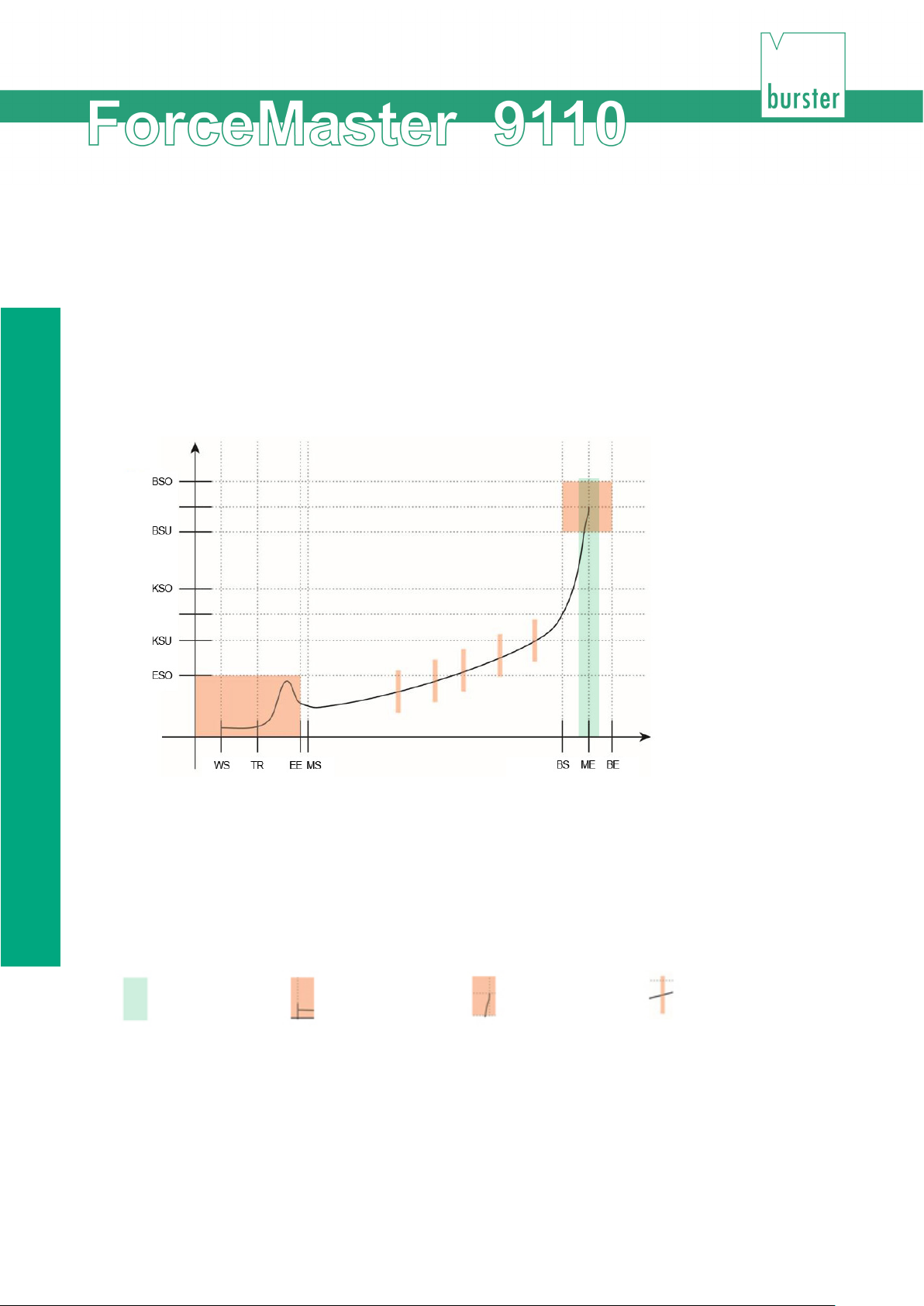
"Languages" menu
The following applies if a peening operation is to be monitored:
Only the peening displacement is monitored. The peening displacement starts when the lower
blocking force threshold is exceeded. The displacement value measured at this position is stored
(peening start position). The maximum peening displacement is determined like a slave pointer.
The relative peening displacement is calculated when the lower blocking force threshold is
exceeded. The peening displacement is monitored for two parameters.
Minimum peening displacement is the displacement that the peening operation must at least have
required. Maximum peening displacement is the displacement that must not be exceeded, since
otherwise manufacturing tolerances will not be observed.
Abbreviations:
WS = displacement start TR = trigger
MS = measurement start ME = measurement end
KSU = force threshold below KSO = force threshold above
BS = block start BE = block end
BSU = block threshold below BSO = block threshold above
EE = end thread in ESO = thread in threshold above
Key:
Region Thread in window Block window Gateway
Special case: Force monitoring only
If no displacement sensor is attached to ForceMaster 9110, none of the monitoring regions can be
used, since the ForceMaster 9110 cannot establish a relationship between force and
displacement.
There is only, therefore, a force threshold below (KSU) and a force threshold above (KSO).
88 of 95
Page 89

Technical data
8. Technical data
General device data
• Display: 2-line illuminated LCD display
• Warding and acknowledgement tones: adjustable signal type
• Warning tone volume: up to 75 dB
• Measurement channels: Force/displacement or force/time
• Interface: USB, RS232
• Mains connection 90 ... 240 V AC / 50 ... 60 Hz
• Cut-off frequency: 1 kHz
• Working temperature range: 0 ... 60 °C
• Air humidity: 10 ... 80 %, no condensation
• Housing type: Aluminum profile housing
• Protection class: IP20
• Connections: coded special connector
• Sampling interval: 10 kHz
• Number of I/O: 8 input / 8 outputs
• Dimensions ( W x H x D): 150 x 95 x 260 [mm]
• Weight: approx. 3 kg
Sensors for the force channel
• Bridge resistor: 350 Ω ... 5 kΩ
• Connecting technology: 4-wire
• Sensor excitation: 5 V
• Excitation current: 20 mA
• Power consumption: approx. 0.3 VA
• Input voltage: 1 mV ... 10 mV
• Deviation: < 1% of full scale
Sensors for the displacement channel
• Sensor type: potentiometric displacement sensor
• Track resistance: 1 kΩ ... 5 kΩ
• Displacement magnitude: 10 mm ... 150 mm
• Deviation: < 1% of full scale
89 of 95
Page 90

Choosing the right load cell
9. Configuration notes
Measurements must be taken to monitor the quality of the pressing processes that are being used
more and more often. You have decided to do this with the ForceMaster 9110.
The press has force and displacement sensors mounted on it for this purpose. These sensors
supply a measurement signal to the ForceMaster 9110. It evaluates the profile of the force in
relation to displacement. If the values exceed or fall below specified limits, the pressing operation
is reported as faulty. The correct choice of sensors is very important if this process is to run
smoothly.
You therefore need a load cell and the displacement sensor. We have arranged for the installation
of the sensors to be as user-friendly as possible. Equipping or retrofitting a press is done quickly.
You only need a few minutes to fit a load cell. The displacement sensor can be mounted in no
more than 15 minutes. Our technology allows the ForceMaster 9110 to be set up for your
particular production process in a very short time.
9.1 Choosing the right load cell
The range of forces appropriate for the sensor to be chosen does not depend on your press, but
on your application. If, for example, the pressing force required for your production operation is
about 200 N, which will be done on a press that can deliver 5 kN, and you buy a load cell capable
of up to 5 kN, it will not supply a useful measurement signal at 200 N, since this is only 4% of the
full-scale value of the sensor. For this example, choosing a sensor with a full-scale value of 500 N
would be appropriate.
The majority of load cells are damaged if they are loaded with twice their rated value. In the
example described, this would appear to happen if we only consider the rated value of the
components, the 5 kN of the press and the 500 N of the sensor. The sensor would be overloaded.
This applies to the majority of load cells. Our Type 8552 load cells can also withstand this kind of
overload.
So do not choose your load cell in the light of the rating of the press, but according to the forces
that will occur in your application.
If you don't know the figure, send us your parts, and we will measure the force. Alternatively you
can request a trial system from us, with one or more load cells, with which you can carry out test
measurements. Once either we or you have found out what the forces that occur are, you can
order the correct load cell.
Presses with different receptacle holes for load cells are available on the market. We can offer
you sensors for receptacle holes with particular graduations between 10 mm and 16 mm that are
suitable for almost any typical commercial press.
90 of 95
Page 91

Configuration notes
9.2 Choosing the right displacement sensor
The stroke of your press is crucial for the choice of displacement sensor. If the press has a stroke
and 50 mm, you can get a 50 mm displacement sensor from us.
Note, however, that the smallest resolution step for a 50 mm displacement sensor is 0.0125 mm
(measured displacement/4000). It is possible that this resolution is to coarse for your application.
In peening operations, the active measuring displacements are often less than 2 mm. This would
mean that in this example you would only be able to resolve 160 steps within the active
measuring window. For some applications this is inadequate.
A 10 mm sensor would be more suitable for the example above. The resolution step size here is
0.0025 mm. This would make 800 resolution steps available for the peening operation, which is
sufficient for a good evaluation. Your displacement sensor should therefore also be chosen in the
light of your application.
An adapter set comes with the displacement sensor, with which you can mount it on practically
any typical commercial press.
9.3 Advice
If you like, we can also make a suitable choice for you. We need your specifications for this.
Contact us, and we will be glad to give you further advice.
91 of 95
Page 92

Advice
10. Available accessories
• 9110-Z001 MasterCard for full configuration access
• 9110-Z002 (PLC card, storage of PLC step chain procedures)
• 9110-Z003 (Tool card for storing the tool data and measuring programs)
• 8552 Load cell
• 5501-Z004 Assembly kit for displacement sensors on manual presses
• 8713 Displacement sensor
• 9900-K349 (USB cable to PC)
• 9900-K333 (RS232 cable to PC)
• 99221-591A-0090030 Connecting cable for potentiometric displacement sensors
with plug-in connections
• 9900-V245 Connecting plug for load cells, sensor calibration data stored
in the plug
• 9900-V221 Connecting plug for potentiometric displacement sensors,
sensor calibration data stored in the plug
• 99005 Connector mounting
• 9110-P001 Configuration and analysis software FMControl
92 of 95
Page 93

Ordering example
ForceMaster
9110 V
x x x
x
Standard
0 0 0 0
Options
Step chain function
1
11. Ordering example
• ForceMaster with PLC function and USB logging, setting up and evaluation
software (under preparation) Type 9110-V0101
Order code
USB stick logging 1
Accessories
• Assembly kit for easy assembly of the displacement sensor to the manual
press Type 5501-Z004
• Connecting cable for potentiometric displacement sensors with plug-in
connection (e.g. 8712) Type 99221-591A-0090030
• RS232 cable to PC Type 9900-K333
• USB cable to PC Type 9900-K349
• MasterCard for full configuration access Type 9110-Z001
• PLC card for saving PLC step chain processes on the card Type 9110-Z002
• Tool card for saving the tool data and measuring program Type 9110-Z003
• Connecting plug for load cells, sensor calibration data stored in the plug Type
9900-V245
• Connecting plug for potentiometric displacement sensors, sensor calibration
data stored in the plug Type 9900-V221
• Connector mounting Type 99005
93 of 95
Page 94
Advice
12. Index
A
Ambient conditions ........................... 10
Assembly kit ................... 40, 41, 91, 92
utoc
onfig ..................... 21, 22, 43, 74
A
Autoconfiguration ..... 12, 21, 26, 39, 44
Automation ....................................... 13
F
Force alarms ................................... 34
Force channel ................................. 88
Force gateways ............................... 84
Force profile .................................... 23
Force threshold .24, 25, 31, 47, 56, 60,
83, 84, 86, 87
B
G
Blocking force .......... 23, 24, 47, 68, 85
Gateways ............................ 38, 47, 84
Grub screw ...................................... 40
C
Cam ................... 31, 32, 33, 60, 61, 62
Cams ................................... 13, 36, 63
Card reader ...................................... 27
Commissioning ................................ 40
Conditions of use ............................. 10
Connecting cable ....................... 91, 92
Connecting plug ......................... 91, 92
Connecting technology .................... 88
Connector pin assignments ............. 37
Conversions ..................................... 11
Counter .......................... 12, 32, 49, 61
Counters .......................................... 50
Customer name ............................... 56
H
Housing type ................................... 88
Humidity .......................................... 10
I
I/O interface..................................... 37
Indicator lamp .................................. 14
Item designation .............................. 72
Item number .................................... 71
94 of 95
D
Data storage .............................. 52, 56
Date ........................................... 56, 79
Dimensions ...................................... 88
Displacement channel ...................... 88
Displacement measurement system
.............................................. 41, 42
Displacement sensor .... 39, 41, 42, 74,
89, 90
Displacement start ........................... 83
Down counter ........... 27, 31, 49, 50, 60
E
Error acknowledgement 37, 39, 46, 68,
69
Error message ......... 27, 34, 39, 45, 52
Error signals ..................................... 68
L
Level ............................................... 25
Load cell ........................ 39, 40, 41, 89
Loudspeaker ................................... 14
M
Mains connection ...................... 15, 88
Mains switch .................................... 15
Manual press ................. 40, 41, 42, 92
Manual presses ............................... 91
Manual settings ............................... 66
Manufacturing tolerances .......... 85, 87
Master card ......................... 27, 34, 39
Master carte .............................. 48, 68
MasterCard ..............27, 34, 39, 48, 68
Measurement chain ......................... 43
Measurement channels ................... 88
Measuring mode ............................. 45
Modes ........................... 20, 21, 22, 43
Page 95

Index
O
Operating temperature ..................... 10
Order data ............................ 56, 71, 72
Order number................. 27, 56, 71, 72
Sensing pin ............................... 74, 75
Standard settings ............................ 75
Statistics .......................................... 73
Status .............................................. 80
Step chain ................28, 32, 35, 57, 61
Storage conditions .......................... 10
Supply voltage ................................. 10
Switching on procedure ................... 39
P
Parts counter.................................... 50
Parts counters .................................. 49
Peening displacement ... 23, 24, 26, 86,
87
Personnel ......................................... 11
PLC .............. 28, 32, 35, 37, 57, 61, 63
PLC card .................................... 27, 63
PLCCard .................................... 27, 63
Press ..... 34, 36, 41, 46, 49, 74, 82, 85,
89, 90
Press head ................................. 40, 42
Press plunger ....................... 36, 40, 42
Pressing curve ................................. 13
Pressing region .......................... 22, 84
Pressing tool .............................. 40, 83
Probe tip .......................................... 41
Profile ......................................... 21, 89
Protection class .......................... 10, 88
R
Readjustment ................................... 42
RS232 ................ 15, 74, 76, 88, 91, 92
T
Teach-in .............................. 21, 22, 43
Text and number input
Thread in force .........23, 25, 26, 47, 83
Thread in process ........................... 84
Time .......................................... 56, 79
Tool card ................................... 27, 63
ToolCard ................................... 27, 63
Tore ................................................ 84
Trigger point .............................. 34, 56
.................. 20
U
USB stick....................... 12, 51, 52, 71
W
Warning ....................................... 9, 68
Warning tone ................................... 68
Warranty...................................... 2, 11
Weight ............................................. 88
Working temperature ....................... 88
Workpiece ... 21, 34, 36, 74, 82, 84, 85,
86
S
Scope of supply ............................... 11
95 of 95
 Loading...