

Page 1

The VS4x1(R)
Video Switcher
and VS8x1(R)
Four/Eight Input
Vertical Interval
with RS232
Manual Version 4.0
ALBUQUERQUE, NM 87109 USA
(505) 898-1455
Made in USA
(505) 898-0159 FAX
www.burstelectronics.com
Hardware, software and manual copyright by Burst Electronics. All rights reserved. No part of this
publication may be reproduced or distributed in any form or by any means without the written permission
of Burst Electronics.
Page 2

Page 3

Four/Eight Input Switcher
Introduction
Congratulations on your purchase of VS4x1/VS8x1 Vertical
Interval Switcher. This manual will explain the various
functions of the VS4x1/VS8x1 (as well as the RS232
options, model VS4x1R/VS8x1R). Unless otherwise stated,
all functions of the VS4x1 are the same for the VS8x1.
Overview
The model VS4x1 is a four (4) input active switcher (VS8x1
is an eight (8) channel active switcher). The appropriate
front panel channel switch selects the output. An LED
indicates the currently selected active channel. Switching
from one video source to another is done during the
vertical interval. Both products use digital logic that inhibits
the selection of an inactive input (no video). This is a safety
feature that can be disabled, explained later. The logic
detects sync to determine if video is present.
Operation
When a channel is selected, the switcher waits for the start
of the next vertical interval to change to the selected input.
If the inputs are synchronous (genlocked), this will allow a
seamless transition from one input to another. All inputs are
DC clamped, at the back porch (color burst), to ground by
the video switcher. The output is also ground referenced. If
there are any level shifts on the incoming video, the video
switcher will eliminate these offsets and ground reference
the outgoing video.
Input Termination
Each channel input has a 75 Ohm termination resistor. This
termination may be removed, resulting in the video
switcher being in the bridging or HiZ mode. This allows
looping of the inputs (looping adapter part number BNC-
1 VS4x1 & VS8x1 Video Switch
Page 4

LOOP). To change the input termination, remove the front
panel, slide the top cover off, and then remove the jumper
shunt for each individual video input (located next to the
BNC connectors, W1 for channel 1, W2 for channel 2, etc.).
A handy place to store the shunt is hanging off one of the
jumper pins.
Video (Sync) Detection
The video switcher allows selection of only active (input
video present) input channels. This feature may be
disabled by either of two ways, front panel control or
internal jumper/DIP switch. For front panel control, turn
power off, press and hold input channel 2 and turn power
on. The video switcher will now select any input, regardless
if video is present. To cancel this feature, cycle power.
When the internal switch/jumper method is used, then
cycling power has no effect.
Jumper/Switch Setting for the Sync Detect
For the VS4x1 there is a DIP switch located inside the unit,
just behind the front panel. Locate the small four (4)
position DIP switch labeled S6. Move switch #2 from the
open (up) position to the closed (down) position. Turn
power on, and now any input can be selected regardless if
there is input video.
For the VS8x1 there is a jumper (W10) located behind the
front panel. A shunt (jumper) has been included with the
unit and is hanging on one of the pins. Place the shunt onto
both pins of W10. Turn power on, and now any input can be
selected regardless if there is input video.
Po w e r
The unit is powered from an external 12Vdc source.
Polarity insensitive, the video switcher has an auto polarity
feature. Do not use AC, use only DC.
Remote Control via RS232 (R Version)
An option is remote control via RS232. The data
transmission is 2400 baud 8-N-1. Any terminal emulation
2 VS4x1 & VS8x1 Video Switch
Page 5

program such as Windows Terminal (HyperTerminal), or
ProComm is all that is required to communicate with the
video switcher.
To cause the device to switch to an active input (video is
present), issue the command: Vx, where x is the channel
number (V2 switches to input #2). The VS switcher will
echo back to the computer Vx (where x is the channel
number). If there is no video present (and detection of
video is enabled) the Vx command will echo back to the
computer “NV” (no video) and not switch. If video detection
is disabled, the VS switcher will only echo back Vx for
channels that have active video present on the input, but
will switch to wherever the command stated.
Audio Switching Using the AS4x1R Audio Switcher
If both audio and video are to be switched, then an
AS4x1R audio switcher is required along with the RS232
controlled video switcher. In this configuration, the video
switcher becomes the controller to the audio switcher. With
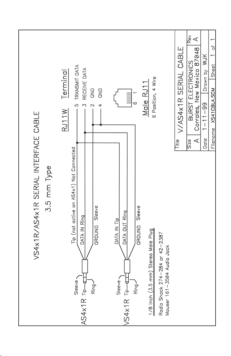
both units connected using a RS232 cable (3.5mm stereo
headphone type cable, with a male plug on each end,
Radio Shack #42-2387), switching of the video switcher
input will cause the audio switcher to follow to the same
input channel.
The audio switcher can do audio breakaway from the video
switcher simply by using the front panel switches on the
AS4x1R. This method of changing the audio input will not
affect which video channel is selected. To have the audio
input changed back to the same video input, simply
reselect the current video input on the video switcher. If you
do not want the audio to switch, but you do want the video
to switch, hold down the appropriate audio input switch
while changing the video input switch.
This function, the AS4x1R following the VS4x1R/VS8x1R,
can be disabled. If this function is disabled, the audio
switcher will not follow the switching commands of the
video switcher. As shipped, the video switchers have the
jumpers set to enable the follow mode function.
3 VS4x1 & VS8x1 Video Switch
Page 6

To disable the follow mode for the VS4x1, remove the front
panel, and slide the top cover off. Locate the four position
DIP switch labeled S6. Move switch #1 from the closed
(down) position to the open (up) position. The VS4x1
switcher will not send data to the AS4x1R or echo data to
the computer.
The follow mode function can be re-enabled two ways,
front panel control or internal jumper. Setting DIP switch S6
#1 to closed (down). For front panel control, press and hold
video switcher channel #1 while power is turned on. This
method operates in follow mode until power is cycled,
follow mode will then be disabled.
To disable follow mode on the VS8x1R, remove the front
panel and slide the top cover off. Located behind the front
panel is a shunted jumper (W9). Remove this shunt.
Replace the top cover and front panel. The video switcher
will not echo data to the computer, or send data to the
AS4x1R.
The follow mode function can be re-enabled two ways.
Reinstall W9 or front panel control. For front panel control,
press and hold video switcher channel #1 while power is
turned on. This method operates in follow mode until power
is cycled, follow mode will then be disabled.
If follow mode is off, the video switch does not echo via the
RS232 port when the channel switches are pressed. If the
follow mode is on then the switch echoes the commands.
Example: with follow mode on when channel 2 is pressed,
then B2 is sent out the RS232 port.
If the commands to the video switch are via the RS232 port
(vs the front panel) then the switch always echoes back the
command. Example: regardless of whether follow mode is
on or off, if V2 is sent to the video switch then it echoes
back V2. There is one case where in the echo returned is
different. If sync detect is on and an inactive channel is
selected the video switch echoes NV (no video). If sync
detect is off, then there is no echo for inactive inputs.
4 VS4x1 & VS8x1 Video Switch
Page 7

Jumper/switch settings:
VS4x1R:
Switch S6 Function Position
1 Follow Mode Up-Off, Down-On
2 Sync Detection Up-On, Down-Off
3 not used
4 not used
VS8x1R:
Jumper Function Position
W9 Follow Mode In-Enabled, Out-Disabled
W10 Sync Detection In-Enabled, Out-Disabled
RS232 Commands:
Command Function
Vx Switches video to “x” channel
Ax Switches audio to “x” channel
Bx Switches both video and audio (AS4x1R)
to “x” channel
CC Responds with Current Channel,
Vx (VS8x1R only)
Responses from switchers:
Responses Function
NV No Video present (if video detect is enabled)
KE Keyboard Error (invalid code sent)
KT Keyboard Time-out error (5 second time-span
to get the data sent to the VS switcher)
Vx Successful video switch to the “x” channel
(only if video is present on the input)
Bx Used in conjunction with the AS4x1R,
successful audio/video switch to the “x”
channel (only if video is present on the input)
5 VS4x1 & VS8x1 Video Switch
Page 8

Specifications:
Video
Switching: Vertical Interval
Bandwidth: 25 MHz
Diff Gain: 0.1 %
Diff Phase: 0.1 deg
S/N: 60 dB
Crosstalk: 60 dB
Output: 75 Ohms 1% DC Clamped
Switching Delay Between Channels: 200 mS
General
Video Connector: BNC, 4-Pin (Mini DIN–Y/C)
Size: VS4x1: 4.1W x 1.5H x 5.5D inches,
VS8x1: 5.6W x 1.5H x 6.5D inches
Power: 8 to 14 Vdc polarity insensitive
Current: VS4x1: 125 mAdc,
VS8x1: 150 mAdc
Wall Module Power Supply Included (center Negative)
Rack Mount VS4x1: Model RM-4 Holds 4 units
Rack Mount VS8x1: Model RM-3 Holds 3 units
There are also rack mounts that hold a mix of VS4x1 and
VS8x1, call us for details.
RS232
Protocol: 2400 Baud 8N1
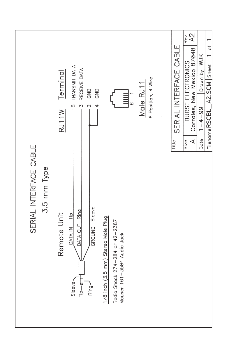
Connector: 1/8 inch stereo (3.5 mm) 3 conductor
Pinout: Tip-Receive Ring-Transmit Sleeve-Ground
6 VS4x1 & VS8x1 Video Switch
Page 9
Page 10
Page 11
Page 12
 Loading...