

Page 1

The MCG-3
and RCG-3
Color Micro Character
Generator
Manual Version 2.01
BURST ELECTRONICS INC
ALBUQUERQUE, NM 87109 USA
(505) 898-1455
Made in USA
(505) 898-0159 FAX
BURSTELECTRONICS.COM
Hardware, software and manual copyright by Burst Electronics. All rights reserved. No part of this publication
may be reproduced or distributed in any form or by any means without the written per mission of Burst
Electronics.
Page 2

Color Micro Character Generator
Table of Contents
Part One: Introduction
About The Manual
Tutorial
Main menu
Screen control menu
Utility menu
Loss of Video Menu
Part Two: Remote Control Tutorial
Waking up the MCG-3
Networking Notes on Cables
Command Reference
Part Three: Technical
Lithium Battery (BR2325)
Notes on “Master Reset”
Troubleshooting and Flashing Lights
Specifications
Jumper Settings
Error Messages
ASCII to MCG-3 Display Convert Table
1 MCG-3 Color Micro Character Generator
Page 3

PART ONE
Please Note:
This manual applies to both the MCG-3 Color Micro Character
Generator and the RCG-3, a remote control only version of the
MCG-3. All statements in this manual apply to both units unless
noted otherwise.
Introduction:
The MCG-3 is a low cost character generator for adding titles or
captioning to NTSC Color or Monochrome video. The MCG-3 will
automatically Genlock to NTSC inputs with no adjustments or switch
settings required. The MCG-3 outputs color characters, appropriate for
logging and documenting experiments, video source I.D., camera and
location display for security applications, time and date stamp from a
PC (or the MCG-3 with the real time clock option), Patient monitoring,
Information displays, and basic CG applications. The MCG-3 can be
operated in stand-alone mode without an incoming video signal.
The unit displays a maximum of 240 characters (10 lines by 24 letters).
Characters may be set to 4 widths and 4 heights for a total of 16
character sizes.
The character set includes both upper and lower case letters A–Z and
a–z, numerals 0–9, and various punctuation marks and symbols as
shown in the MCG-3 character table. Characters may be set to one of
seven colors or transparent and can be made to flash. The character box
or background behind the characters may also be set on a page by page
basis.
The display memory holds 10 pages of text and is protected from
power loses by a lithium cell that should last 8 to 10 years. Stored on a
page by page basis for each page is: the character size, display position,
background and letter color status, and the position of the Real Time
Clock Display.
2 MCG-3 Color Micro Character Generator
Page 4

The MCG-3 may be controlled by either front panel controls or
remotely by an RS232 link to a PC, the RCG-3 is remote control only.
Multiple units may be chained together with standard RJ11 modular
telephone cable and individually accessed from a PC. Easy to use two
letter commands are sent to the MCG-3 from a PC running a terminal
emulation program (such as Qmodem or Procomm), from Windows
Run Terminal, or from user written software.
The MCG-3 has 3 LEDs: Power, RS232 Activity (Remote), and OnLine status.
About This Manual:
This manual is divided into three sections. Section One is a tutorial and
describes initial setup and MCG-3 front panel operation. Section Two
describes how to remotely control one MCG-3 or a network of MCG3’s from a Personal Computer. Also included in Section Two is a
reference section describing how to use each of the two letter remote
control commands. Section Three has information on specifications,
troubleshooting etc.
When reading the next section, the Tutorial, it is best to have the MCG3 in front of you to get a full understanding of the operation of the
MCG-3.
Material Supplied:
In the shipping carton you should find:
1 MCG-3 Color Micro Character Generator
1 AC adapter 12 Vdc/500mA
1 Operations manual
1 Three foot modular telephone cable (RJ11 Type)
1 DB-9 (RS232) to RJ11 (Telephone cord) adapter
1 Floppy Disk (Containing example software for remote control)
3 MCG-3 Color Micro Character Generator
Page 5

Operation:
Power up the MCG-3 using the AC adapter or an external source of 12
Vdc. The MCG-3 has an auto polarity feature for the DC input
(polarity is unimportant). Connect a video source (black burst, VCR,
live video, etc.) to the VIDEO-IN BNC connecter. Connect the
VIDEO-OUT BNC connecter to a composite monitor. The RS232 host
and loop RJ11 connectors will be discussed in Section Two.
The RJ11 connectors are for remote control of the MCG-3 from a PC
computer RS232 port, and not for direct connection to a telephone
system.
Switch the unit on. When the unit is powered up it goes to On Line
status and displays the page it was set for the last time it was powered
up. The Green POWER LED and the red ON LINE LED should glow.
The page will appear blank if there is no text present. (If no text is
displayed and the page is not blank or if the green Power LED is
flashing, see the section on troubleshooting.)
The following section applies to the MCG-3 only and not the RCG-3.
The RCG-3 does not have any front panel control switches. It is
designed for remote control applications.
The MCG-3 may be controlled either by front panel controls or via an
RS232 link to a PC. This section will discuss front panel control.
(Remote control via a PC is discussed in Section Two.)
Front panel controls use menus on the screen to guide the user in
editing text or setting options. There are 4 menus:
MM
CGCG
-3 M-3 M
AA
II
N MN M
EE
NN
TT
T
TT
UU
U
UU
EE
E
EE
E
EE
RORO
RO
RORO
O MO M
O M
O MO M
N
NN
L ML M
L M
L ML M
UU
U
UU
EE
NN
UU
E
N
U
EE
NN
UU
EE
NN
UU
E
N
U
EE
NN
UU
MM
AA
II
N MN M
EE
NN
M
MM
A
I
N M
AA
II
N MN M
UU
E
N
U. The UP and
EE
NN
UU
M
CG
-3 M
A
I
EE
E
EE
TT
T
TT
N CN C
N C
N CN C
Y MY M
Y M
Y MY M
F VF V
F V
F VF V
N M
AA
II
N MN M
OO
NN
O
N
OO
NN
EE
NN
E
N
EE
NN
II
DD
I
D
II
DD
MM
CGCG
-3 M-3 M
SS
CC
RR
EE
S
C
R
E
SS
CC
RR
EE
UU
TT
II
LILI
U
T
I
LI
UU
TT
II
LILI
LL
OO
SS
S OS O
L
O
S
S O
LL
OO
SS
S OS O
As each new menu is brought up, move the arrow to the item of interest
and read the manual description.
Press the MENU button now to go to the
4 MCG-3 Color Micro Character Generator
Page 6

DOWN arrow buttons will move the arrow to select the different menu
items. The following details each menu item.
Main Menu:
EE
DD
II
T PT P
AGAG
E
D
I
EE
DD
II
Move the arrow to
cursor will appear. The cursor may be moved left or right with the
arrow buttons, and up or down by holding SHIFT and pressing the
arrow buttons. Holding the arrow keys for more than about a second
will cause the key to repeat, moving the cursor across the screen.
Characters may be selected by pressing the PLUS or MINUS keys.
Holding down the PLUS or MINUS keys will cause the characters to
cycle up or down. The cycling will stop briefly at the beginning and
end of: the ABC’s, the numbers, and the punctuation marks and
symbols.
The color and flashing characteristic of each character may be set by
holding down the SHIFT key and pressing the PLUS or MINUS key.
The cursor and current character will be changed to the new color. This
color will become the “current” color and subsequent characters will be
added in the new color. NOTE: when cycling through the colors using
the SHIFT and PLUS or MINUS key, the colors will follow this
sequence: color-1, color-1 (flashing), color-2, color-2 (flashing) and so
on. See page 21 for color sequence.
Try setting some titles to get a feel for using
EE
DD
II
E
D
I
EE
DD
II
EE
T P
AG
E
T PT P
AGAG
EE
T PT P
AGAG
EE
T P
AG
E press the MENU key.
T PT P
AGAG
EE
EE
DD
II
T PT P
AGAG
E
D
I
EE
DD
II
EE
T P
AG
E. Press the MENU key. A flashing
T PT P
AGAG
EE
EE
DD
II
T PT P
E
D
I
T P
EE
DD
II
T PT P
AGAG
EE
AG
E. To exit from
AGAG
EE
DD
II
SS
PP
LALA
Y PY P
AGAG
D
I
S
P
LA
DD
II
SS
PP
LALA
Pressing the MENU key displays the currently selected page. Pressing
the DISP key will cause the unit to toggle between on line and off line.
Pressing the PLUS or MINUS keys will switch the unit to the next
higher or lower page. There are ten pages that may be selected.
5 MCG-3 Color Micro Character Generator
Y P
Y PY P
AG
AGAG
EE
E
EE
Page 7

Once you have set text on all your pages, this is the menu item you will
use to recall them. Press the MENU key to exit.
CC
HH
AA
NN
GG
E PE P
AGAG
C
H
A
N
G
CC
HH
AA
NN
GG
This is another way to change pages. Pressing the PLUS or MINUS
keys will change the current page and show the page number.
SS
ET BET B
ACAC
S
ET B
AC
SS
ET BET B
ACAC
Pressing the PLUS (+) or MINUS (-) keys will change the background
color for the current page. Setting the background to
result in a transparent background, i.e. just the characters will be keyed
over the incoming video. Full page background colors can be obtained
by continuing to press the PLUS (+) key until
menu item. Set the background color and then go to
see what the page looks like with different background colors. Note
that in the Full Background mode, the video generated by the unit is no
longer genlocked. This should not present a problem unless you are
using an external mixer vs. the internal mixer of the unit.
Change the background color and then go to
what the page looks like with different background colors.
SS
ET VET V
EE
S
ET V
E
SS
ET VET V
EE
SS
ET HET H
OO
S
ET H
O
SS
ET HET H
OO
This menu item sets the size of the characters displayed with
PP
AGAG
EE
P
AG
E. Move the arrow to
PP
AGAG
EE
Pressing the PLUS or MINUS keys will change the character size for
the current page.
After setting a character size, go to
characters look like.
Character size is stored on a page by page basis such that each page
may have a different character size. On a given page, all characters are
of the same size.
EE
E P
AG
E
E PE P
AGAG
EE
KGKG
RORO
UU
NN
KG
KGKG
RR
T (VT (V
R
T (V
RR
T (VT (V
RR
Z (Horizontal) SZ (Horizontal) S
R
Z (Horizontal) S
RR
Z (Horizontal) SZ (Horizontal) S
DD
RO
U
N
D
RORO
UU
NN
DD
ertical) Sertical) S
ertical) S
ertical) Sertical) S
II
I
II
ZZ
Z
ZZ
SS
S
SS
EE
E
EE
II
ZZ
I
Z
II
ZZ
ET HET H
ET H
ET HET H
ZZ
EE
RO (0)RO (0)
Z
E
RO (0) will
ZZ
EE
RO (0)RO (0)
FF
UU
LLLL
F
U
LL is observed on the
FF
UU
LLLL
DD
II
SS
PP
LALA
Y PY P
AGAG
D
I
S
P
LA
DD
II
SS
PP
LALA
DD
II
SS
PP
LALA
Y PY P
D
I
S
P
DD
II
SS
PP
EE
E
EE
OO
RR
Z SZ S
II
ZZ
EE
SS
O
R
Z S
I
OO
Z
RR
Z SZ S
II
ZZ
DD
II
SS
PP
LALA
D
I
S
P
LA
DD
II
SS
PP
LALA
E or
EE
Y PY P
Y P
Y PY P
S
ET V
SS
AGAG
AG
AGAG
ET VET V
ET VET V
AGAG
LA
Y P
AG
LALA
Y PY P
AGAG
EE
RR
T ST S
E
R
T S
EE
RR
T ST S
EE
E to see what the
EE
Y P
AG
Y PY P
AGAG
EE
E to see
EE
DD
II
SS
PP
D
I
S
P
DD
II
SS
PP
II
ZZ
EE
I
Z
E.
II
ZZ
EE
EE
E to
EE
LALA
LA
LALA
YY
Y
YY
6 MCG-3 Color Micro Character Generator
Page 8

Screen Control Menu:
SS
ET HET H
OO
RR
S
ET H
SS
ET HET H
SS
ET VET V
S
ET V
SS
ET VET V
This menu item sets the display position of the characters on the video
monitor. The display position may be set by either pressing the PLUS
or MINUS keys, or by pressing the MENU key.
If you pressed the MENU key, the current page is displayed. You can
move the page left and right by pressing the arrow keys, or up and
down by pressing SHIFT and the arrow keys.
Display position is stored on a page by page basis such that each page
may have a different display position.
Press MENU to exit.
CC
LEALEA
C
LEA
CC
LEALEA
Pressing the MENU key clears only the currently selected page.
CC
LEALEA
C
LEA
CC
LEALEA
Pressing the MENU key clears all 10 pages. (Use this one with
caution!)
DD
II
SS
D
I
S
DD
II
SS
Pressing the MENU key will display on the screen in large print (the ID
code used to access the MCG-3 in a network of linked MCG-3’s). This
is useful in setting up a network of MCG-3’s.
Press MENU to exit.
Z (Horizontal) PZ (Horizontal) P
O
R
Z (Horizontal) P
OO
RR
Z (Horizontal) PZ (Horizontal) P
EE
RR
T (VT (V
E
R
T (V
EE
RR
T (VT (V
R PR P
AGAG
EE
R P
AG
E
R PR P
AGAG
EE
R AR A
LL PLL P
R A
LL P
R AR A
LL PLL P
PP
LALA
Y IY I
D OD O
P
LA
Y I
D O
PP
LALA
Y IY I
D OD O
ertical) Pertical) P
ertical) P
ertical) Pertical) P
AGAG
EE
SS
AG
E
S
AGAG
EE
SS
N SN S
CC
N S
C
R
N SN S
CC
OO
S (PS (P
osition)osition)
O
S (P
osition)
OO
S (PS (P
osition)osition)
OO
S (PS (P
osition)osition)
O
S (P
osition)
OO
S (PS (P
osition)osition)
RR
EE
EE
NN
E
E
N
RR
EE
EE
NN
CC
LL
OO
CC
K DK D
II
SS
PP
LALA
C
L
O
C
K D
CC
LL
OO
CC
K DK D
This menu item is used to set a display position for the Real Time
Clock option. If this option is not installed, this item will default to
7 MCG-3 Color Micro Character Generator
YY
I
S
P
LA
Y
II
SS
PP
LALA
YY
Page 9

OO
FF
FF
O
F
F. For more information, see the
OO
FF
FF
the rear of this manual.
RR
EAEA
L TL T
II
MM
E CE C
LL
OO
CC
R
EA
L T
I
M
L TL T
E C
II
MM
E CE C
RR
EAEA
KK
L
O
C
K addendum at
LL
OO
CC
KK
Utility Menu:
NN
O CO C
LL
OO
CC
K IK I
NN
STST
AA
LLELLE
N
O C
L
O
C
K I
N
NN
O CO C
LL
OO
This menu item will change to
option is installed. For more information, see the REAL TIME CLOCK
addendum at the rear of this manual.
DD
II
AGAG
NN
I
AG
II
AGAG
ET BET B
ET B
ET BET B
OO
N
O
NN
OO
PP
AA
P
A
PP
AA
AA
A
AA
D
DD
This item tests RAM, ROM, tests the RS232 (Remote control) port, and
checks if the real time clock is running, if installed. Note that the
RS232 test requires a loop back plug. See Section Three for more
information on building a loop back plug. Results of the tests will be
either
Pressing the MENU key runs the tests. To exit, press the MENU key
after the test.
SS
S
SS
Pressing the PLUS or MINUS keys will set the baud rate (1200, 1800,
2400, 4800 & 9600) for the RS232 link. (The baud rate is stored in
battery backed memory.)
CC
STST
ST
STST
SS
S
SS
UU
U
D RA
UU
K IK I
NN
II
CC
I
C
II
CC
SS
EE
S
E
SS
EE
D RAD RA
D RAD RA
ST
STST
SS
S
SS
D!D!
D! or
D!D!
TT
T
TT
DD
A
LLE
D
AA
LLELLE
DD
SS
ET CET C
LL
OO
CC
S
ET C
SS
ET CET C
FF
AA
II
LELE
DD
F
A
I
LE
D.
FF
AA
II
LELE
DD
EE
E
EE
KK
L
O
C
K when the real time clock
LL
OO
CC
KK
SS
ET DET D
EVEV
II
CC
E IE I
S
ET D
EV
SS
ET DET D
EVEV
Pressing the PLUS or MINUS keys will set the ID code used to access
the MCG-3 in a network of linked MCG-3’s (The ID is stored in
battery backed memory.)
8 MCG-3 Color Micro Character Generator
DD
I
C
E I
D
II
CC
E IE I
DD
Page 10

MM
AA
STST
EE
R RR R
EE
SS
M
A
ST
E
MM
AA
STST
EE
Resets MCG-3 to factory defaults as follows:
Character is size set to smallest size for all pages.
Display position is centered for all pages.
Background is set to ON for all pages.
Baud rate is set to 9600 baud.
Device ID code is set to 01.
Clock display is set to OFF.
This menu item is useful is you want to “start over from scratch.”
This menu item should also be used after replacing the lithium battery,
or to recover from a “Flashing Power LED” condition. (See Section
Three for more information.)
Note that text pages are not erased by this menu item. If you want to erase
all the pages, use
VV
EE
RR
SS
II
V
VV
Pressing the MENU key will show the version number of the ROM
software and a copyright statement. You may need this information if
you ever need to call the factory for technical support.
OO
E
R
S
I
O
EE
RR
SS
II
OO
R R
R RR R
N NN N
N N
N NN N
ETET
E
S
ET
EE
SS
ETET
CC
LEALEA
R AR A
LL PLL P
AGAG
EE
C
LEA
R A
R AR A
LL P
LL PLL P
CC
LEALEA
UU
MM
BB
EE
RR
U
M
B
E
R
UU
MM
BB
EE
RR
SS
AG
E
S on the Screen Control Menu.
AGAG
EE
SS
Loss of Video Menu:
LL
OO
SS
S DS D
ETET
EE
CTCT
II
OO
L
O
S
S D
LL
Pressing the PLUS or MINUS key will change the loss of video mode
to ON or OFF respectively. With loss of video set to OFF, the unit will
output the incoming video signal (which, if video has been lost, will be
a blank screen). With loss of video set to ON, if the input video signal
is lost, the unit will switch to a default background screen.
ET
OO
SS
S DS D
ETET
9 MCG-3 Color Micro Character Generator
NN
E
CT
I
O
N
EE
CTCT
II
OO
NN
Page 11

DD
EE
FF
AA
UU
LL
T PT P
AGAG
D
E
F
A
U
DD
Pressing the PLUS or MINUS key will change the default page for loss
of video. If the default page is set to 0 (zero), then the unit will display
the current page on loss of video. If the default page is set to a valid
page (1–10), upon loss of video, that page will be displayed.
DD
D
DD
Upon loss of video, the time delay in switching to the internally
generated video can be set from
(in 10 second increments) by depressing the +/- buttons. The return to
genlocked mode will be instantaneous once a good video signal is
received. If white noise, such as that generated by a VCR playing an
unrecorded tape or a satellite link with loss of signal, is to be detected
the delay mode should be set to
the external video will be delayed 2–3 seconds so the MCG-3 can
ascertain that an acceptable video signal is present.
L
EE
FF
AA
UU
LL
EE
LALA
Y MY M
E
LA
Y M
EE
LALA
Y MY M
T P
T PT P
EE
AG
E
AGAG
EE
OO
DD
EE
O
D
E
OO
DD
EE
OO
FF
FF
O
F
F (switches instantly) to 90 seconds
OO
FF
FF
WW
T_NT_N
OO
II
SS
W
WW
T_N
T_NT_N
EE
O
I
S
E. In this mode the return to
OO
II
SS
EE
10 MCG-3 Color Micro Character Generator
Page 12

PART TWO
Remote Control Tutorial
WARNING!!! – DO NOT CONNECT YOUR
MCG-3 UNIT TO A TELEPHONE SYSTEM.
DAMAGE WILL RESULT AND YOUR
WARRANTY MAY BE VOIDED.
The RJ11 connectors are for remote control of the MCG-3 from a PC
computer, and not for use with the telephone.
Your MCG-3 may be controlled from a PC computer via the
computer’s RS232 (serial) port by sending the MCG-3 simple two
letter commands (See the command reference for more information on
commands).
We provide:
1 RJ11 cable (36 inch)
1 DB9 to RJ11 adapter (DB25 to RJ11 also available)
You will need the following:
1 PC computer with a RS232 Serial Port
1 terminal emulation program such as Qmodem or Procomm
(ANSI.SYS compatible). From Windows, run Terminal; from Windows
95, select HyperTerminal.
You will need to determine if you have one or two RS232 ports, and
CC
OO
the name of the one you plan to use. The names will be
CC
OO
M2:M2:
C
O
M2:. If you have only one RS232 port then the correct name is
CC
OO
M2:M2:
CC
OO
M1:M1:
C
O
M1:.
CC
OO
M1:M1:
We’ll start by connecting the DB9-to-RJ11 adapter to the RS232 port
you have chosen. Next, connect one end of the RJ11 (Telephone Type)
C
CC
M1:M1:
O
M1: or
OO
M1:M1:
11 MCG-3 Color Micro Character Generator
Page 13

cable to the DB9 to RJ11 adapter, and connect the other end to the
RJ11 connecter on the MCG-3 marked HOST. (It is assumed that the
MCG-3 is connected to a video source and a monitor, and that the
MCG-3 is turned on.)
Next, run your communications program. You will need to set up the
program for the following:
CC
OO
Set the COM port to either
(Depending on what you chose earlier.)
Baud rate: 9600 baud
(Unless you changed it in the
Stop bits: 1
Data bits: 8
Parity: None
Echo: Off (or Set Duplex to Full)
Note that other combinations may not work reliably or may not work at
all, so please double check your connections and communications
program setup. Also confirm that the MCG-3
00
11
0
1, in the utility menu.
00
11
If you did everything correctly, then when you type on your computer
keyboard the REMOTE light should flash.
M1:M1:
C
O
M1: or
CC
OO
M1:M1:
Utility MenuUtility Menu
Utility Menu)
Utility MenuUtility Menu
CC
OO
M2:M2:
C
O
M2:
CC
OO
M2:M2:
Device IDevice I
Device I
Device IDevice I
DD
D code is set to
DD
12 MCG-3 Color Micro Character Generator
Page 14

Networking:
Your MCG-3 may be used as a stand alone unit, or in a network of
linked MCG-3’s. Networking allows more than one MCG-3 to be
controlled from a single PC computer, over a single RS232 link.
A MCG-3 network is much like the a telephone party line, where each
subscriber may listen in but only one person is allowed to talk at any
one time. Because of this, each MCG-3 may be put to sleep or woke up
and in this way only one MCG-3 will talk at any one time.
Each MCG-3 in a network is assigned a unique ID number. (See “Set
UU
TT
II
LILI
TT
Y MY M
EE
NN
device ID” in the
wake up an MCG-3 so you can send it commands.
The ID on the RCG-3 must be set before the units are connected as a
network.
U
T
I
LI
T
UU
Y M
TT
II
LILI
TT
Y MY M
UU
E
N
U in Part One). This number is used to
EE
NN
UU
Waking Up the MCG-3
When first powered up the MCG-3 will be asleep, meaning that it will
WW
AA
KK
ignore any data sent to it except for a
front panel keypad will work whether the MCG-3 is awake or asleep).
The wake command format is as follows:
>W>W
K,idK,id
>W
K,id
>W>W
K,idK,id
idid
Where
id is the device ID number.
idid
WW
AA
KK
After receiving a
the following:
##
id Rid R
EAEA
DD
#
id R
##
id Rid R
CC
OO
MM
C
O
M
CC
OO
MM
>_>_
>_
>_>_
Again, the
receive commands.
YY
EA
D
Y
EAEA
DD
YY
MM
AA
NN
D?D?
M
A
N
D?
MM
AA
NN
D?D?
II
DD
I
D is the device number. At this time the MCG-3 is ready to
II
DD
EE
W
A
K
E command the responding MCG-3 will send
WW
AA
KK
EE
EE
W
A
K
E command. (However, the
WW
AA
KK
EE
13 MCG-3 Color Micro Character Generator
Page 15

To switch to another MCG-3 on the network, first issue a sleep
command as follows:
>S>S
PP
>S
P
>S>S
PP
WW
AA
This will put all MCG-3’s on the network to sleep. Next issue a
command using the ID number for the MCG-3 you wish to work with.
SS
LELE
EE
Note that the
SS
LELE
EE
PP
S
LE
E
P command puts all MCG-3’s on the network to sleep.
SS
LELE
EE
PP
PP
S
LE
E
P command does not use an ID number; instead, the
SS
LELE
EE
PP
W
WW
KK
A
K
AA
KK
Notes On Cables:
Your MCG-3 uses standard RJ11 modular telephone cable. This type of
cable was chosen because of its low cost and ease of use.
RJ11 cable (with connectors) is widely available in various lengths, or
customs lengths can be fabricated. You can make you own cable (Radio
Shack stocks cable, connectors, and the crimping tool), or often a
telephone supply house can fabricate custom length cables.
The cable has four conductors and uses four conductor RJ11
connectors. The connectors should be attached so as to have the
locking “snap” tab facing the same way on both ends of the cable. See
Figure One or use the sample cable that came with your MCG-3 as an
example. Some cable has a rib along one side to aid in orienting the
connectors.
EE
E
EE
Connecting the MCG-3
To connect several MCG-3’s together, proceed as follows:
Run an RJ11 cable from the PC computer to the RS232 HOST
connecter on the first MCG-3. Next connect another RJ11 cable from
the RS232 LOOP connecter on the first MCG-3 to the RS232 HOST
connecter on the next MCG-3. The process repeats for all MCG-3’s on
the network. See Figure Two.
14 MCG-3 Color Micro Character Generator
Page 16

The RJ11 cabling should be a direct connection from one MCG-3 unit
to the next. Do not use “Y” connectors or try to double up units. Also
the computer MUST be first in line on the network.
If the layout of a building is such that the computer should be in the
middle of the cabling, you might want to split the network between two
COM ports on the computer. See Figure Three.
Video Cabling
Video cabling is set up a bit different than the RJ11 cables. If multiple
MCG-3s will be using the same video source, then a video DA, such as
the Burst Model VDA-4 or VDA-8, must be used between the video
source and the MCG-3s. The MCG-3 VIDEO-OUT connecter is
connected to a video monitor. The monitor should be terminated in 75
ohms.
If the MCG-3 units will use separate video sources, then connect each
video source to its MCG-3 and the VIDEO-OUT of the MCG-3 to its
video monitor.
15 MCG-3 Color Micro Character Generator
Page 17

COMMAND REFERENCE:
Your MCG-3 may be remotely controlled by sending two letter
commands. The commands in this section are listed in alphabetical
order.
All commands have the same basic format, as follows:
CC
C,X, YC,X, Y
C
C,X, Y
CC
C,X, YC,X, Y
CC
Where:
XX
X and
XX
Parameters are information the command needs to operate. These may
be page and line numbers or something else. Parameters may be one or
two characters long. Some commands take one parameter, others take
two, and some don’t use parameters at all.
An example:
The following command,
MCG-3 memory:
WW
W
WW
This sequence will write THIS IS A TEST to page 8, line 3 of the
MCG-3.
To display the page that has this line, use the
command:
DD
P,8P,8
D
P,8
DD
P,8P,8
In this case we used only one parameter.
To get started, first be sure to read the remote control tutorial and
WW
W
WW
get familiar the remote control commands. If you will be controlling
your MCG-3 manually then you will simply send the MCG-3
commands with a communications program. If you will be writing
CC
C
C is the two letter command itself.
CC
CC
YY
Y are operation parameters.
YY
WW
W
WW
L,8,3, TL,8,3, T
L,8,3, T
L,8,3, TL,8,3, T
AA
A
AA
HH
II
S IS I
S A TS A T
EE
H
I
S I
S A T
HH
II
S IS I
S A TS A T
KK
II
NN
G UG U
K
KK
PP
I
N
G U
P the MCG-3. Then look over the command reference to
II
NN
G UG U
PP
STST
E
ST
EE
STST
RR
II
TT
E LIE LI
NN
R
I
T
RR
II
TT
EE
E LI
N
E, will write a line of text to the
E LIE LI
NN
EE
DD
II
SS
PP
LALA
D
DD
Y PY P
I
S
P
LA
Y P
II
SS
PP
LALA
Y PY P
AGAG
AG
AGAG
EE
E
EE
16 MCG-3 Color Micro Character Generator
Page 18

your own software to control your MCG-3, look at the example
programs on the floppy disk that came with your MCG-3.
These example programs show how to send commands and how to set
RR
EAEA
DD
MM
EE
.D.D
OO
up the serial port of a PC computer. See the
floppy disk for more information.
The description of each command is formatted as follows:
PURPOSE: Tells what the command does.
FORMAT: Shows the correct format for the command. Either upper or
lower case characters are acceptable (case insensitive). Commas must
separate commands and all parameters.
DESCRIPTION: Describes in detail how the command is used.
EXAMPLE: Shows one or more examples of how to use the command.
R
EA
D
M
RR
EAEA
DD
MM
E
.D
O
EE
.D.D
OO
CC
C file on the
CC
17 MCG-3 Color Micro Character Generator
Page 19

Command List
Name Command Action
BB
Background
Baud Rate
Clear All
Change Color
Clock Display
Clear PC Screen
Clear Page
Character Size
Clear Video
Date Location
Delay Mode
Display Page
Edit Page
Help
Loss Detect
Loss Page
Master Reset
Display ID
Mixer
IBM PC Type
Page Position
Run Diagnostics
Read Line
Set Current Page
Set Date
Set ID
Sleep
Set Responds
Set Time
Time Format
Time Location
Version Number
Wake
Write Line
18 MCG-3 Color Micro Character Generator
GG
B
G Sets background color.
BB
GG
BB
RR
B
R Sets the serial baud rate.
BB
RR
CC
AA
C
A Clears all pages.
CC
AA
CC
CC
C
C Changes the current text color
CC
CC
CDCD
CD Turns TIME/DATE ON/OFF.
CDCD
CC
LL
C
L Clears PC Screen.
CC
LL
CPCP
CP Clears one page.
CPCP
CC
SS
C
S Sets character size.
CC
SS
CVCV
CV Clears only Video Display screen.
CVCV
DD
LL
D
L Date location on video.
DD
LL
DD
MM
D
M Delay on Loss of Video.
DD
MM
DD
PP
D
P Displays page on video.
DD
PP
EE
PP
E
P Allows editing of a page.
EE
PP
HH
EE
H
E Prints help screen to PC.
HH
EE
LDLD
LD Sets Loss Detect on/off.
LDLD
LPLP
LP Sets Loss of Video page.
LPLP
MM
RR
M
R Performs Master Reset.
MM
RR
II
DD
I
D Displays MCG-3 network ID on video.
II
DD
MXMX
MX Sets Mixer to on or off line.
MXMX
PP
CC
P
C Sets Control for IBM Type PC.
PP
CC
PP
PP
P
P Sets position of page on screen.
PP
PP
RR
DD
R
D Runs diagnostic tests.
RR
DD
RR
LL
R
L Prints MCG-3 text line to PC.
RR
LL
SS
CC
S
C Sets the current page.
SS
CC
SS
DD
S
D Sets the date of Real Time Clock.
SS
DD
SS
II
S
I Sets unit ID.
SS
II
SS
PP
S
P Puts all devices on network to sleep.
SS
PP
SS
RR
S
R Turns responses from commands on or off
SS
RR
(for high speed communication).
STST
ST Set time of day for Real Time Clock.
STST
TT
FF
T
F Display format for Time of Day.
TT
FF
TT
LL
T
L Time Location on Video Update.
TT
LL
VNVN
VN Prints ROM software version number to PC.
VNVN
WW
KK
W
K Wakes up a device on the network.
WW
KK
WW
LL
W
L Writes a line of text to the MCG-3.
WW
LL
Page 20

BB
G BG B
ACAC
KGKG
RORO
UU
NN
B
G B
AC
BB
PURPOSE: Set the background color for the current page.
FORMAT:
DESCRIPTION: Sets the background color for the currently selected
page. Background color is stored on a page by page basis.
To enable Full Background mode, add an “F” (case insensitive) after
the color number.
EXAMPLE:
KG
G BG B
ACAC
KGKG
p = 0 indicates a transparent background
p = (1–8) sets background to color (1–8)
BB
G,3G,3
B
G,3 Sets the background color for the currently
BB
G,3G,3
BB
G,3fG,3f
B
G,3f Sets to color 3 with full background on.
BB
G,3fG,3f
Code Screen Color
1 Black
2 Red
3 Green
4 Orange
5 Blue
6 Magenta
7 Cyan
8 White
RO
RORO
BB
B
BB
G,pG,p
G,p
G,pG,p
DD
U
N
D
UU
NN
DD
selected page to color 3.
19 MCG-3 Color Micro Character Generator
Page 21

BB
R BR B
AA
UU
D RAD RA
TT
B
R B
A
U
BB
R BR B
AA
UU
PURPOSE: Sets the serial interface baud rate.
FORMAT:
x = baud rate code
EXAMPLE:
BB
R,4R,4
B
R,4 Sets the baud rate to 9600
BB
R,4R,4
Code Baud Rate
0 1200
1 1800
2 2400
3 4800
4 9600
D RA
D RAD RA
BB
B
BB
T
TT
R,xR,x
R,x
R,xR,x
EE
E
EE
20 MCG-3 Color Micro Character Generator
Page 22

CC
A CA C
LEALEA
R AR A
C
A C
LEA
CC
A CA C
LEALEA
PURPOSE: Clears all 10 pages in the MCG-3 memory.
FORMAT:
DESCRIPTION: Clears all 10 pages in the MCG-3 memory. This
command does not clear the MCG-3 screen (See the
DD
II
SS
PP
LALA
D
I
S
P
LA
DD
II
SS
PP
LALA
used with caution. This command needs no parameters.
LLLL
R A
LL
R AR A
LLLL
CC
AA
C
A
CC
AA
CD, CCD, C
LEALEA
CD, C
LEA
CD, CCD, C
LEALEA
YY
Y command). For obvious reasons this command should be
YY
RR
R
RR
21 MCG-3 Color Micro Character Generator
Page 23

CC
C CC C
HH
AA
NN
GG
E CE C
OO
LL
OO
C
C C
H
A
N
G
CC
C CC C
PURPOSE: Changes the current text color
FORMAT:
p = 0–1 sets current text color to transparent
p = (2–15) sets current text color
DESCRIPTION: Changes the current text color. After changing the
current text color, subsequent writes will be done in the new color. The
following table lists the numbers and associated colors.
Color Number Resulting Color
0 or 1 Transparent
2 Orange
3 Orange (flashing)
4 Green
5 Green (flashing)
6 Yellow
7 Yellow (flashing)
8 Dark Blue
9 Dark Blue (flashing)
10 Red
11 Red (flashing)
12 Light Blue
13 Light Blue (flashing)
14 White
15 White (flashing)
E C
HH
AA
NN
GG
E CE C
CC
C,pC,p
C
C,p
CC
C,pC,p
RR
O
L
O
R
OO
LL
OO
RR
EXAMPLE:
CC
C,4C,4
C
C,4 Sets current text color to Green.
CC
C,4C,4
22 MCG-3 Color Micro Character Generator
Page 24

CD CCD C
LL
OO
CC
K DK D
II
SS
PP
LALA
CD C
L
O
C
CD CCD C
PURPOSE: Turns time and date display on or off.
FORMAT:
DESCRIPTION: This command sets the on/off status for the date and
time of day displays. This display status is stored on a page by page
basis. If the RTC option is not installed, issuing this command will
produce a
K D
LL
OO
CC
K DK D
DD
S,xS,x
D
S,x
DD
S,xS,x
x = T for TIME display only
x = D for DATE display only
x = B to display BOTH time and date
x = O (Not zero) to turn OFF both time and date display
RR
EAEA
R
EA
RR
EAEA
I
II
S
P
SS
L TL T
L T
L TL T
YY
LA
Y
PP
LALA
YY
II
MM
E CE C
LL
OO
CC
K NK N
OO
T IT I
NN
STST
AA
LLELLE
I
M
E C
L
O
C
K N
O
T I
N
II
MM
E CE C
LL
OO
CC
K NK N
ST
OO
T IT I
NN
STST
A
AA
LLE
LLELLE
DD
D error.
DD
23 MCG-3 Color Micro Character Generator
Page 25

CC
L (or CL (or C
C
L (or C
CC
L (or CL (or C
PURPOSE: Clears the PC Screen.
FORMAT:
DESCRIPTION: This command will send back to the PC a
SS
CC
S
C
SS
CC
PC screen gets cluttered up from previous commands. Note: this
command is used only when the MCG-3 is being controlled through a
communications program, and is not intended for use with user written
software.
LS) Clear PLS) Clear P
LS) Clear P
LS) Clear PLS) Clear P
CC
LL
C
L or
CC
LL
RR
EE
EE
NN
R
E
E
N code to clear the PC’s video screen. This is useful when the
RR
EE
EE
NN
C ScrC Scr
eeneen
C Scr
een
C ScrC Scr
eeneen
CC
LSLS
C
LS
CC
LSLS
CC
C
CC
LEALEA
LEA
LEALEA
RR
R
RR
24 MCG-3 Color Micro Character Generator
Page 26

CP CCP C
LEALEA
R PR P
AGAG
CP C
LEA
CP CCP C
LEALEA
PURPOSE: Clears one page.
R P
R PR P
AG
AGAG
EE
E
EE
FORMAT:
DESCRIPTION: Clears the page indicated. Page is cleared in the
MCG-3 memory only. This command does not clear the MCG-3 screen
(See the
EXAMPLE:
CP,pCP,p
CP,p
CP,pCP,p
p = page number 1 through 10
CD, CCD, C
LEALEA
R DR D
II
SS
PP
LALA
CD, C
LEA
LEALEA
R D
R DR D
CD, CCD, C
CP,4CP,4
CP,4 Clears page 4 in MCG-3 memory.
CP,4CP,4
YY
I
S
P
LA
Y).
II
SS
PP
LALA
YY
25 MCG-3 Color Micro Character Generator
Page 27

CC
S CS C
HH
AA
RACTRACT
EE
R SR S
II
ZZ
C
S C
H
A
RACT
CC
S CS C
HH
AA
PURPOSE: Sets character size for a page.
FORMAT:
x = Horizontal size 1 through 4
y = Vertical size 1 through 4
DESCRIPTION: Sets character size for the current page. There are 16
sizes available (4 horizontal, 4 vertical). Character size is stored on a
page by page basis. If there are more characters on a page in memory
than will fit on the screen for the current character size, as many
characters as is possible from the upper left portion of the page will be
displayed. The following tables will show how many characters and
lines will by displayed for different character sizes.
Horz. size No. of characters (per line)
120
212
38
46
RACTRACT
CC
C
CC
E
EE
S,x,yS,x,y
S,x,y
S,x,yS,x,y
R S
R SR S
EE
I
Z
E
II
ZZ
EE
Vert. size No. of lines (per page)
19
26
34
43
EXAMPLE:
CC
S,2,2S,2,2
C
S,2,2 Sets character size to display 12 characters
CC
S,2,2S,2,2
by 6 lines.
26 MCG-3 Color Micro Character Generator
Page 28

CV CCV C
LEALEA
R VR V
II
DD
EE
CV C
LEA
LEALEA
R V
R VR V
CV CCV C
PURPOSE: Clears the MCG-3 Video Display.
OO
I
D
E
O
II
DD
EE
OO
FORMAT:
DESCRIPTION: This command clears the MCG-3 Video display
screen but not any of the ten pages of the MCG-3 memory.
CVCV
CV
CVCV
27 MCG-3 Color Micro Character Generator
Page 29

DD
L DL D
AA
TT
E LE L
OO
CC
AA
TT
II
OO
D
L D
A
T
E L
DD
L DL D
PURPOSE: Sets the display position of the date (RTC) display.
FORMAT:
DESCRIPTION: Sets the display position for date display maintained
in the Real Time Clock option. If this option is not installed, issuing
this command will produce a
error. The display position is stored on a page by page basis.
O
AA
TT
E LE L
OO
DD
D,xx,yyD,xx,yy
D
D,xx,yy
DD
D,xx,yyD,xx,yy
xx = Two digit horizontal position, 01 through 13
yy = Two digit vertical position, 00 through 09
NN
C
A
T
I
O
N
CC
AA
TT
II
OO
NN
RR
EAEA
L TL T
II
MM
E CE C
LL
OO
CC
K NK N
OO
T IT I
NN
STST
AA
R
EA
L T
I
M
E C
L
O
C
K N
O
RR
EAEA
L TL T
II
MM
E CE C
LL
OO
CC
K NK N
T I
OO
T IT I
LLELLE
N
ST
A
LLE
NN
STST
AA
LLELLE
DD
D
DD
28 MCG-3 Color Micro Character Generator
Page 30

DD
M DM D
EE
LALA
Y MY M
OO
DD
DD
D
DD
O
OO
M,xM,x
M,x
M,xM,x
EE
D
E
DD
EE
LP (Loss PLP (Loss P
LP (Loss P
LP (Loss PLP (Loss P
Loss Detect (LD)Loss Detect (LD)
Loss Detect (LD)
Loss Detect (LD)Loss Detect (LD)
(LD,(LD,
11
))
(LD,
1
). During the delay there is no output from
(LD,(LD,
11
))
age)age)
age)
age)age)
D
M D
E
LA
DD
M DM D
PURPOSE: Sets delay, in seconds, after input video is lost before page
defined by LP command is displayed.
FORMAT:
DESCRIPTION: After loss of input video is detected, a preset delay
can be set before the page of text defined by the
command is displayed. This applies only if the
command is set “ON”
the unit. Code 1 (white noise) is used when, upon loss of video, the
input becomes white noise such as loss of signal from a satellite feed or
the end of a tape on a VCR. Special software within the unit analyzes
the noise to determine if valid video (sync) is present or if it is just
random noise.
EXAMPLE:
Y M
EE
LALA
Y MY M
x=0 to 9
DD
M,4M,4
D
M,4 Sets the delay to 30 seconds
DD
M,4M,4
Code Delay
0 Off (no delay)
1 White Noise
2 10 seconds
3 20 seconds
4 30 seconds
5 40 seconds
6 50 seconds
7 60 seconds
8 70 seconds
9 80 seconds
29 MCG-3 Color Micro Character Generator
Page 31

DD
P DP D
II
SS
PP
LALA
Y PY P
AGAG
D
P D
I
S
P
DD
P DP D
PURPOSE: Displays a page, in the MCG-3 memory, on the screen.
FORMAT:
DESCRIPTION: The MCG-3 holds 10 pages of text. This command
copies any one page to the screen. The contents of the pages in memory
are unaffected.
If the character size for the page is larger than size 1 vert., 1 horz., only
a portion of the page may be displayed. (See the CS, character size,
command for more details).
EXAMPLE:
LA
II
SS
PP
LALA
DD
D
DD
p = Page to be displayed 1 through 10
DD
P,P,
77
D
P,
7 Copies page seven to the screen.
DD
P,P,
77
Y P
Y PY P
P,pP,p
P,p
P,pP,p
AG
AGAG
EE
E
EE
30 MCG-3 Color Micro Character Generator
Page 32
EE
P EP E
DD
II
T PT P
AGAG
E
P E
D
I
EE
P EP E
DD
II
T P
T PT P
AG
AGAG
EE
E
EE
PURPOSE: Edit a page from a remote location.
EE
FORMAT:
E
EE
P,pP,p
P,p
P,pP,p
p = Page to be edited 1 through 10
DESCRIPTION: This command displays, on the PC, a copy of the
referenced page to the PC and allows editing of the page, on a line by
line basis, on the computer screen.
Page 7 ID01
43 2 1
THIS IS A TEST
4
3
2
1
PLEASE STAND BY
ONE MOMENT PLEASE
ENTER LINE NUMBER?__
Line #
1
2
3
4
5
6
7
8
9
10
Computer Monitor Screen
31 MCG-3 Color Micro Character Generator
Page 33

Type ^C for command line.
Type ^F to toggle Flash.
Type ^B to toggle Background.
After issuing this command, the MCG-3 asks for a line number. Enter
the desired line. (Line numbers are printed on the right side of the box.)
The text line is reprinted in the second box, and the third box down
then is blanked. Enter the text for this line in the third box, then press
return. Now the new text is printed back to the first box. Continue this
EE
DD
II
T PT P
AGAG
process until all desired lines are entered. To exit
The numbers on the left and top of the first box are a guide to indicate
how many characters will fit across the MCG-3 screen for different
character sizes.
For example, in the above figure for character size 3 horizontal, 4
vertical: only the word THIS would by displayed on the MCG-3
screen. Similarly, if the character size were 1 horizontal, 2 vertical, then
the words THIS IS A TEST followed by PLEASE STAND BY would
by displayed. However the words on line 7, ONE MOMENT
PLEASE, would not be displayed.
Front panel controls will be inoperative while this command is
executing.
The communications software used must be ANSI.SYS compatible
(most are); also, you must have the statement DEVICE=ANSI.SYS in
configconfig
your
communications program for more detail.
.sys.sys
config
.sys file. See the documentation that came with your
configconfig
.sys.sys
E
D
I
EE
DD
II
T P
T PT P
EE
AG
E press ^C.
AGAG
EE
32 MCG-3 Color Micro Character Generator
Page 34

HH
E HE H
EE
LPLP
H
E H
E
LP
HH
E HE H
EE
LPLP
PURPOSE: Prints a help screen to the PC.
HH
EE
HH
EE
FORMAT:
DESCRIPTION: This command displays, on the PC a brief list of all of
the remote control commands and their parameters. This listing may be
exited from at any time by pressing Ctrl-C on the PC keyboard.
Front panel controls will be inoperative while this command is
executing.
If the entire help screen is not visible, make sure the terminal emulation
program is set for no line feed after carriage return. In Procomm, this is
accomplished with Alt-F3.
H
HH
E or
EE
LPLP
H
E
LP
HH
EE
LPLP
33 MCG-3 Color Micro Character Generator
Page 35

II
D DD D
II
SS
PP
LALA
Y IY I
I
D D
I
S
II
D DD D
II
SS
PURPOSE: Displays the network ID code on the MCG-3 screen.
FORMAT:
DESCRIPTION: The network ID code is the code used to access the
MCG-3 in a
the MCG-3 screen. This is useful in diagnosing a network spread over a
large building. This command also echoes the ID back over the serial
interface.
DD
P
LA
Y I
D
PP
LALA
Y IY I
DD
II
DD
I
D
II
DD
WW
AA
KK
EE
W
A
K
E command. This command displays the ID code on
WW
AA
KK
EE
34 MCG-3 Color Micro Character Generator
Page 36

LD LLD L
OO
SS
S DS D
ETET
EE
LD L
O
S
LD LLD L
PURPOSE: Enables loss of video detect mode.
S D
OO
SS
S DS D
ET
ETET
CTCT
E
CT
EE
CTCT
FORMAT:
DESCRIPTION: If loss of video detect is desired, set LD to on
Upon loss of incoming video, the unit will generate an internal NTSC
signal (this is referred to as the standalone mode) and display the page
of text defined by the
given or the
be displayed. If the loss video detect is set to off
will not generate an output upon loss of input video.
EXAMPLE:
LD,xLD,x
LD,x
LD,xLD,x
x = 1 equals off
x = 0 equals on
LP (Loss PLP (Loss P
LP (Loss P
LP (Loss PLP (Loss P
LPLP
LP command is set to 0
LPLP
LD,LD,
11
LD,
1 Loss of video is on.
LD,LD,
11
age)age)
age) command. If no
age)age)
(LD,(LD,
11
(LD,
1
(LD,(LD,
11
LPLP
LP command is
LPLP
(LP,0)(LP,0)
(LP,0) then the current page will
(LP,0)(LP,0)
(LD,0)(LD,0)
(LD,0) then the unit
(LD,0)(LD,0)
))
).
))
35 MCG-3 Color Micro Character Generator
Page 37

LP LLP L
OO
SS
S PS P
AGAG
LP L
O
S
LP LLP L
OO
SS
PURPOSE: Defines what page of the internal 10-page memory is
displayed upon loss of incoming video.
S P
S PS P
AG
AGAG
EE
E
EE
FORMAT:
DESCRIPTION: If the loss of video detect is on
will switch to a standalone mode and internally generate a NTSC signal
and display the page defined by this command. If this command is set
to zero
EXAMPLE:
LP,xLP,x
LP,x
LP,xLP,x
x = 0 to 10
(LP,0)(LP,0)
(LP,0) then the current page is displayed.
(LP,0)(LP,0)
LP,4LP,4
LP,4 Display page 4 of memory.
LP,4LP,4
(LD,(LD,
11
))
(LD,
1
) then the unit
(LD,(LD,
11
))
36 MCG-3 Color Micro Character Generator
Page 38

MM
R MR M
AA
STST
EE
R RR R
EE
SS
M
R M
A
ST
MM
R MR M
PURPOSE: Resets the unit to factory default settings.
FORMAT:
DESCRIPTION: See the section towards the end of this manual
entitled “NOTES ON
function of
EXAMPLE:
E
AA
STST
EE
MM
M
MM
Master RMaster R
Master R
Master RMaster R
MM
RR
M
R Performs a master reset.
MM
RR
R R
R RR R
RR
R
RR
ETET
E
S
ET
EE
SS
ETET
MM
AA
STST
EE
R RR R
EE
SS
M
A
MM
AA
eseteset
eset.
eseteset
ST
STST
E
EE
ETET
R R
E
S
ET” for a description of the
R RR R
EE
SS
ETET
37 MCG-3 Color Micro Character Generator
Page 39

MX MMX M
II
XX
EE
MX M
MX MMX M
PURPOSE: Sets MCG-3 line status.
RR
I
X
E
R
II
XX
EE
RR
FORMAT:
DESCRIPTION: This command sets the ONLINE (Mixer ON,
characters are present) and OFFLINE (Mixer OFF, characters are NOT
present) status of the MCG-3. The looped though video is not affected
(other than the character overlay). The contents of the MCG-3 page,
memory are not affected.
EXAMPLE:
MX,xMX,x
MX,x
MX,xMX,x
x = 1 for Mixer On (ONLINE)
x = 0 for Mixer Off (OFFLINE)
MX,MX,
11
MX,
1 Sets MCG-3 to ONLINE. ONLINE LED ON.
MX,MX,
11
38 MCG-3 Color Micro Character Generator
Page 40

PP
C SC S
ET FOET FO
R PR P
C OC O
RR
II
EE
NN
TT
AA
TT
II
OO
P
C S
ET FO
R P
C O
R
I
E
PP
C SC S
ET FOET FO
R PR P
C OC O
PURPOSE: Sets Edit Page command to use IBM PC extended “Line
Draw” characters.
PP
FORMAT:
x = 1 for IBM PC
x = 0 for non IBM PC
DESCRIPTION: Sets whether or not the
use IBM PC (XT, AT) extended ASCII characters to build the “edit”
boxes. This command is used when the MCG-3 will be controlled
through non-IBM PC equipment, such as a dumb terminal. The default
for this command is 1 for IBM PC. This setting is maintained in battery
back RAM.
P
PP
C,xC,x
C,x
C,xC,x
N
RR
II
EE
NN
NN
T
A
T
I
O
N
TT
AA
TT
II
OO
NN
EE
DD
II
T PT P
AGAG
E
D
I
EE
DD
II
EE
T P
AG
E command will
T PT P
AGAG
EE
39 MCG-3 Color Micro Character Generator
Page 41

PP
P PP P
AGAG
E PE P
OO
SS
II
TT
II
OO
P
P P
AG
E P
PP
P PP P
PURPOSE: Sets the position of the page on the screen.
FORMAT:
DESCRIPTION: This command sets the horizontal and vertical
position of a page on the screen. The page position may need
adjustment after changing a character size, or you may want to position
text over an object on the incoming video (such as redoing a telephone
number on a commercial).
The numbers used to specify the vertical and horizontal positions are
arbitrary. For the MCG-3 (but not the RCG-3), probably the best way
to determine what position you may want, for a given situation, is to
manually adjust an MCG-3 to the position you want, and use the
numbers on the screen (in the
this command.
O
AGAG
E PE P
OO
PP
P
PP
x = Horizontal position
y = Vertical position
S
I
T
SS
II
TT
P,x,yP,x,y
P,x,y
P,x,yP,x,y
NN
I
O
N
II
OO
NN
SS
CC
RR
EE
EE
N CN C
OO
NN
TT
RORO
S
C
R
E
E
N C
SS
CC
RR
O
EE
EE
N CN C
OO
LL
N
T
RO
L menu) to send with
NN
TT
RORO
LL
40 MCG-3 Color Micro Character Generator
Page 42

RR
D RD R
UU
N DN D
II
AGAG
NN
OO
STST
II
CC
R
D R
U
N D
I
AG
RR
D RD R
UU
N DN D
PURPOSE: Runs diagnostic tests from a remote location.
FORMAT:
DESCRIPTION: This command is exactly the same command used in
the utility menu and as such it displays the results of the tests on BOTH
the MCG-3 screen and the PC screen. The results of the RS232 loop
test are not sent to the PC as a loop plug can not be installed while the
PC is connected to the MCG-3. However, if you would like your
software to be able to conduct the RS232 loop test, simply echo back
all characters sent by the MCG-3 after the results of the ROM test. The
test string sequence, in ASCII, is as follows:
(space)1234567890(space)abcdefghijklmnopqrstuvwxyz
(space)1234567890(space)ABCDEFCHIJKLMNOPQESTUVWXYZ
Spaces are 32d (ASCII).
Possible results of the RAM and ROM tests are as follows:
Testing RAM...(space)RAM Test Passed!
Testing RAM...(space)RAM Test Failed.
Testing ROM...(space)ROM Test Passed!
Testing ROM...(space)ROM Test Failed.
Each line ends with a carriage return (13d), linefeed (10d).
One easy way to interpret the results of the tests is to look for either a
period or an exclamation point just before the carriage return, line feed.
The results of the diagnostics test will flash momentarily on the video
screen, then the video will return to the last page displayed. The results
will be maintained on the PC screen.
II
RR
R
RR
AGAG
DD
D
DD
N
NN
SS
O
ST
I
C
S
OO
STST
II
CC
SS
41 MCG-3 Color Micro Character Generator
Page 43

RR
L RL R
EAEA
D LID LI
NN
R
L R
EA
RR
L RL R
EAEA
PURPOSE: Reads one line from the MCG-3 memory.
FORMAT:
p = Page number 1 through 10
1 = line number 1 through 9
DESCRIPTION: This command reads any line in the MCG-3 memory,
given the page and line number. Results are in ASCII. However, if a
character is displayed in bold (meaning BG-Background is On) or is
flashing, the corresponding ASNI.SYS codes will also be sent.
Codes are defined as follows:
Function ANSI code
Bold on ESC[7m
Flash on ESC[5m
All attr. off ESC[0m
Note that ESC is ASCII code 27d.
EXAMPLE: If the string THIS IS A TEST is in the MCG-3 memory at
page 1, line 1 and the word IS is flashing the sequence read by the
command
THIS ESC[5misESC[0m A TEST
followed by a carriage return (13d), and line feed (10d).
If there were no flashing or bolded characters the sequence read would
be
THIS IS A TEST
again followed by a carriage return (13d), and line feed (10d).
D LI
D LID LI
RR
R
RR
RR
R
RR
EE
N
E
NN
EE
L,p,lL,p,l
L,p,l
L,p,lL,p,l
L,L,
11
,,
11
L,
1
,
1 would be:
L,L,
11
,,
11
42 MCG-3 Color Micro Character Generator
Page 44

SS
C SC S
ET CET C
UU
RR
RR
EE
NN
T PT P
AGAG
S
C S
ET C
U
R
R
E
SS
C SC S
ET CET C
PURPOSE: Provides a means of setting the current page without
affecting the video display.
FORMAT:
p = page number 1 through 9
DESCRIPTION: This command is used in conjunction with commands
that affect the current page. This command allows the current page to
be changed without affecting the video display, so that undisplayed
pages may be changed or edited while another page is being displayed.
EXAMPLE:
DD
P,P,
11
D
P,
1 Display Page 1 to Video Screen
DD
P,P,
11
SS
C,5C,5
S
C,5 Current Page is now 5
SS
C,5C,5
BB
G,0G,0
B
G,0 Set Page 5 Background OFF
BB
G,0G,0
PP
P,P,
11
2,22,2
P
P,
1
2,2
PP
P,P,
11
2,22,2
DD
P,5P,5
D
P,5 Display Page 5
DD
P,5P,5
N
UU
RR
RR
EE
NN
SS
C,pC,p
S
C,p
SS
C,pC,p
11
1 Set Current Page (5) to 12 Horizontal,
11
T P
AG
T PT P
AGAG
21 Vertical
EE
E
EE
43 MCG-3 Color Micro Character Generator
Page 45

SS
D SD S
ET DET D
AA
TT
S
D S
ET D
SS
D SD S
ET DET D
PURPOSE: Sets the date maintained in the RTC option.
FORMAT:
mm = Two digit month 01 through 12
dd = Two digit date 01 through 31
yy = Two digit year 00 through 99
DESCRIPTION: This command sets the date maintained in the RTC
option. The Real Time Clock will automatically detect and adjust for
leap year. If the RTC option is not installed, issuing this command will
produce a
EE
A
T
E
AA
TT
EE
SS
D,mm-dd-yyD,mm-dd-yy
S
D,mm-dd-yy
SS
D,mm-dd-yyD,mm-dd-yy
RR
EAEA
L TL T
II
L T
L TL T
MM
I
M
II
MM
R
EA
RR
EAEA
E CE C
E C
E CE C
LL
OO
CC
K NK N
OO
T IT I
NN
STST
AA
LLELLE
L
O
C
K N
O
T I
N
LL
OO
CC
K NK N
ST
OO
T IT I
NN
STST
A
AA
LLE
LLELLE
DD
D error.
DD
44 MCG-3 Color Micro Character Generator
Page 46

SS
I SI S
ET IET I
S
I S
SS
I SI S
PURPOSE: Sets the network ID code for the unit.
FORMAT:
DESCRIPTION: Used to set the ID of each unit when multiple units
are on the same RS232 port. If only one unit is on the RS232 port, set
the ID to 01 (factory default). To set an ID, connect only one unit at a
time to the serial port and set its ID. Note that the
WW
(
W
WW
is possible, although a little risky, to have more than one unit with the
same ID on the same RS232 port; the
(S(S
(S
(S(S
EXAMPLE:
DD
ET I
D
ET IET I
DD
SS
I,xxI,xx
S
I,xx (hex)
SS
I,xxI,xx
xx = 01 to FF
WW
AA
KK
EE
W
A
K
E command
WW
AA
KK
EE
K,0K,0
11
K,0
1) must be sent before sending any other command to the unit. It
K,0K,0
11
Set RSet R
espesp
onsesonses
esp
onses must be off
espesp
onsesonses
R,0)R,0)
R,0) in that case.
R,0)R,0)
II
D,04D,04
I
D,04 Sets the ID to 04
II
D,04D,04
Set R
Set RSet R
45 MCG-3 Color Micro Character Generator
Page 47

SS
P SP S
LELE
EE
S
P S
SS
P SP S
PURPOSE: Puts all devices in the network to sleep.
FORMAT:
DESCRIPTION: This command is used when you want switch control
from the PC to another MCG-3 on the network. The sleep command
causes all MCG-3’s on the network to ignore all data sent to them
except for the
The front panel controls a active whether the MCG-3 is asleep or
awake.
EXAMPLE: The following sequence will access two MCG-3’s and
send each some commands.
PP
LE
E
P
LELE
EE
PP
SS
PP
S
P
SS
PP
WW
AA
KK
EE
W
A
K
E command. See the
WW
AA
KK
EE
WW
K,0K,0
11
W
K,0
1 Unit with ID 01 is awake
WW
K,0K,0
11
DD
P,P,
11
00
D
P,
1
0 Display page 10 on unit 01
DD
P,P,
11
00
SS
PP
S
P Put all units asleep
SS
PP
WW
K,02K,02
W
K,02 Now accessing unit 02
WW
K,02K,02
CP,5CP,5
CP,5 Clears Page 5 of unit 02
CP,5CP,5
WW
W
WW
AA
A
AA
KK
EE
K
E command.
KK
EE
46 MCG-3 Color Micro Character Generator
Page 48

SS
R SR S
ET RET R
EE
SS
PP
OO
NN
SS
EE
S
R S
ET R
E
S
SS
R SR S
ET RET R
PURPOSE: Turns responses from commands on or off.
FORMAT:
x = 2 “>” prompt
x = 1 Responses on
x = 0 Responses off
DESCRIPTION: When responses are set to off, the corresponding unit
will not send ANY data to the PC but will still accept commands. Also,
the MCG-3 front panel controls become inoperative. There are
basically three situations where you might want to use this command.
First, if you want to send commands to more than one unit at a time
(see the example below). This way, the units on the network won’t try
to all talk at once. Second, if you want to send commands at high speed
(9600 baud - no wait between characters). Because the unit won’t have
to spend time echoing back received characters or processing the
signals from the front panel controls, it will have more time to process
incoming characters at high speed. The third situation is to lockout the
front panel controls on the MCG-3 to prevent unauthorized use.
Set RSet R
If
Set R
Set RSet R
the unit will only respond with a “>” prompt. The purpose of this is to
allow for faster data transfers at 9600 baud (although you can use other
baud rates). The “>” character acts as a line pacing character. When the
unit receives a line of data, after processing that data and when the unit
is ready to receive more data, the unit will send a “>” character. At this
time the unit is ready for another line of data. This method of data
transfer is compatible with most terminal programs that support ASCII
data transfers.
If for some reason your software should miss the “>” character (line
noise, etc.), the unit will not send another “>” character. Your software
P
EE
SS
PP
SS
R,xR,x
S
R,x
SS
R,xR,x
espesp
onsesonses
esp
onses is set to 2
espesp
onsesonses
SS
O
N
S
E
S
OO
NN
SS
EE
SS
(S(S
R,2)R,2)
(S
R,2) then after receiving a line of data,
(S(S
R,2)R,2)
47 MCG-3 Color Micro Character Generator
Page 49

should time out and try to resend the line of data in this case. Also, the
first line sent should be a blank line (only a carriage return/line feed).
After sending the blank line, you should look for the “>” character.
This has two purposes: first, it will clear the unit’s serial buffer, and
second, you can confirm that the unit is in response mode 2.
WW
AA
KK
Caution: When sending a
unit is hung up because the
when really the unit has had its responses set to off. Also if a unit is in
SS
LELE
EE
PP
S
LE
E
P mode it will not respond to an
SS
LELE
EE
PP
OO
FF
are set to
reminder.
EXAMPLE: The following sequence will send a command to more
than one unit:
SS
S
SS
WW
W
WW
SS
S
SS
WW
W
WW
SS
S
SS
WW
W
WW
SS
S
SS
WW
W
WW
SS
S
SS
WW
W
WW
SS
S
SS
SS
S
SS
WW
W
WW
SS
S
SS
SS
S
SS
WW
W
WW
SS
S
SS
SS
S
SS
FF
O
F
F, the Yellow REMOTE LED will glow constantly as a
OO
FF
FF
PP
P All units asleep
PP
K,0K,0
11
K,0
1 Unit 01 is awake
K,0K,0
11
R,0R,0
R,0 Responses for unit 01 are OFF
R,0R,0
K,02K,02
K,02 Unit 02 is awake
K,02K,02
R,0R,0
R,0 Responses for unit 02 are OFF
R,0R,0
K,03K,03
K,03 Unit 03 is awake
K,03K,03
R,0R,0
R,0 Responses for unit 03 are OFF
R,0R,0
L,L,
11
,,
11
,T,T
EE
STST
II
NN
L,
1
,
1
,T
L,L,
11
,,
11
,T,T
PP
P Put all units to sleep
PP
K,0K,0
11
K,0
1 Unit 01 is awake
K,0K,0
11
R,R,
11
R,
1 Responses for unit 01 are ON
R,R,
11
PP
P Put all units to sleep
PP
K,02K,02
K,02 Unit 02 is awake
K,02K,02
R,R,
11
R,
1 Responses for unit 02 are ON
R,R,
11
PP
P Put all units to sleep
PP
K,03K,03
K,03 Unit 03 is awake
K,03K,03
R,R,
11
R,
1 Responses of unit 03 are ON
R,R,
11
PP
P Put all units to sleep
PP
GG
E
ST
I
N
G Write TESTING to all awake units
EE
STST
II
NN
GG
EE
W
A
K
E command, it is possible to think that a
WW
AA
KK
EE
WW
AA
KK
EE
W
A
K
E command didn’t send a response,
WW
AA
KK
EE
SS
R,R,
11
S
R,
1 command. When responses
SS
R,R,
11
48 MCG-3 Color Micro Character Generator
Page 50

ST SST S
ET TET T
II
MM
ST S
ET T
ST SST S
ET TET T
PURPOSE: Sets the time maintained in the RTC option.
EE
I
M
E
II
MM
EE
FORMAT:
DESCRIPTION: This command sets the time of day maintained in the
RTC option. The Real Time Clock can operate in military (24 hour) or
standard (12 hour) formats. To operate in military time use MT in place
of xx above, to operate in standard time use AM or PM. If the RTC
option is not installed, issuing this command will produce a
TT
II
MM
T
I
M
TT
II
MM
ST,hh:mm:xxST,hh:mm:xx
ST,hh:mm:xx
ST,hh:mm:xxST,hh:mm:xx
hh - Two digit hour, 01 through 12 (or 01 through 23 for MT)
mm - Two digit minute, 00 through 59
xx - MT (Military 24 hour mode)
RR
EAEA
R
EA
RR
EAEA
E CE C
LL
OO
CC
K NK N
OO
T IT I
NN
STST
AA
LLELLE
E C
E CE C
L
O
C
K N
O
T I
N
LL
OO
CC
K NK N
ST
OO
T IT I
NN
STST
A
AA
LLE
LLELLE
DD
D error.
DD
LL
L
LL
49 MCG-3 Color Micro Character Generator
Page 51

TT
F TF T
II
MM
E FOE FO
RR
MM
AA
T
F T
I
M
TT
PURPOSE: Sets the display format for the time of day.
FORMAT:
DESCRIPTION: This command sets the time of day display format.
The time format is stored on a page by page basis. If the RTC option is
not installed, issuing this command will produce a
CC
C
CC
EXAMPLE:
E FO
F TF T
II
MM
E FOE FO
x = 1 for no seconds displayed (12:59)
x = 2 for AM/PM indicator (12:59 AM)
x = 3 for seconds display (12:59:59)
LL
OO
CC
K NK N
L
O
LL
OO
C
K N
O
OO
CC
K NK N
OO
TT
F,3F,3
T
F,3 Sets RTC for Seconds Display
TT
F,3F,3
TT
L,L,
11
3,03,0
T
L,
1
3,0
TT
L,L,
11
3,03,0
CD,TCD,T
CD,T Turn on Time display
CD,TCD,T
TT
R
M
A
T
RR
MM
AA
TT
TT
F,xF,x
T
F,x
TT
F,xF,x
RR
EAEA
L TL T
EA
EAEA
L T
L TL T
II
I
II
R
RR
T IT I
NN
STST
AA
LLELLE
T I
N
ST
T IT I
NN
STST
99
9 Time to be displayed in lower right corner
99
A
AA
LLE
LLELLE
DD
D error.
DD
NN
EE
N
E
NN
EE
50 MCG-3 Color Micro Character Generator
Page 52

TT
L TL T
II
MM
E LE L
OO
CC
AA
TT
II
OO
T
L T
I
M
E L
TT
L TL T
PURPOSE: Sets the display position of the time of day (RTC) display.
FORMAT:
DESCRIPTION: Sets the display position for the time display
maintained in the Real Time Clock option. If this option is not
installed, issuing this command will produce a
NN
OO
T IT I
N
O
T I
NN
OO
T IT I
page basis.
O
II
MM
E LE L
OO
TT
T
TT
xx - Two digit horizontal position, 01 through 13
yy - Two digit vertical position, 00 through 10
NN
STST
AA
LLELLE
N
ST
A
LLE
NN
STST
AA
LLELLE
NN
C
A
T
I
O
N
CC
AA
TT
II
OO
NN
L,xx,yyL,xx,yy
L,xx,yy
L,xx,yyL,xx,yy
RR
EAEA
L TL T
II
L T
L TL T
MM
I
M
II
MM
R
EA
RR
EAEA
DD
D error. The display position is stored on a page by
DD
E CE C
E C
E CE C
LL
OO
CC
KK
L
O
C
K
LL
OO
CC
KK
51 MCG-3 Color Micro Character Generator
Page 53

VN VVN V
EE
RR
SS
II
OO
N NN N
UU
MM
BB
EE
VN V
E
R
S
I
O
VN VVN V
PURPOSE: Prints the ROM software version number to the PC.
N N
EE
RR
SS
II
OO
N NN N
RR
U
M
B
E
R
UU
MM
BB
EE
RR
FORMAT:
DESCRIPTION: This command print the version number of the ROM
software and a copyright statement to the PC.
VNVN
VN
VNVN
52 MCG-3 Color Micro Character Generator
Page 54

WW
K WK W
AA
KK
W
K W
WW
K WK W
PURPOSE: Wakes up an MCG-3 that is in sleep mode
FORMAT:
DESCRIPTION: This command is used when you want switch control
of the PC to another MCG-3 on the network. The
causes the referenced MCG-3’s to start accepting data after previously
being asleep. See the
Also see “Waking up the MCG-3” in the Remote control tutorial.
The ID code may be a decimal number in the range 00 to 99, or
hexadecimal number in the range 00 to FF.
EXAMPLE:
EE
A
K
E
AA
KK
EE
WW
K,idK,id
W
K,id
WW
K,idK,id
id = Two digit network ID code
SS
LELE
EE
PP
S
LE
E
P command.
SS
LELE
EE
PP
WW
K,0K,0
11
W
K,0
1 Unit 01 is awake
WW
K,0K,0
11
SS
PP
S
P Unit 01 is asleep
SS
PP
WW
K,F7K,F7
W
K,F7 Unit F7 is awake
WW
K,F7K,F7
SS
PP
S
P Unit F7 is asleep
SS
PP
WW
W
WW
AA
KK
A
K
AA
KK
EE
E command
EE
53 MCG-3 Color Micro Character Generator
Page 55

WW
L WL W
RR
II
TT
E LIE LI
NN
W
L W
R
I
WW
PURPOSE: Write a line of text to the MCG-3 memory.
FORMAT:
DESCRIPTION: This command will send one line of text to the MCG3 memory.
EXAMPLE:
To cause a word to flash, use the
T
L WL W
RR
II
TT
p = Page number (1 through 10) of where text will go.
1 = Line number (1 through 10) of page where text will go.
text = Text to be sent to page, 24 characters max.
WW
L,2,5,TL,2,5,T
W
L,2,5,T
WW
L,2,5,TL,2,5,T
CC
C,4C,4
C
C,4 Sets color to Green
CC
C,4C,4
WW
L,L,
11
W
L,
1
WW
L,L,
11
CC
C,5C,5
C
C,5 Sets color to Green (flashing)
CC
C,5C,5
WW
L,L,
11
W
L,
1
WW
L,L,
11
CC
C,4C,4
C
C,4 Sets color to Green
CC
C,4C,4
WW
L,L,
11
W
L,
1
WW
L,L,
11
E LI
E LIE LI
WW
W
L,p,l,text
WW
,4,T,4,T
,4,T
,4,T,4,T
,4,T,4,T
,4,T
,4,T,4,T
,4,T,4,T
,4,T
,4,T,4,T
EE
N
E
NN
EE
L,p,l,textL,p,l,text
L,p,l,textL,p,l,text
HH
II
S IS I
S A TS A T
EE
H
I
S I
S A T
HH
II
S IS I
S A TS A T
HH
II
S IS I
S A TS A T
H
I
S I
S A T
HH
II
S IS I
S A TS A T
HH
II
S IS I
SS
H
I
S I
S Changes “THIS IS” characters to
HH
II
S IS I
SS
HH
II
SS
H
I
S Changes “THIS” to Green
HH
II
SS
STST
E
ST Will write THIS IS A TEST
EE
STST
to page 2, line 5.
WW
LL
W
L function multiple times:
WW
LL
EE
STST
E
ST Writes text in Green
EE
STST
Green (flashing)
TT
HH
II
S IS I
S A TS A T
EE
RESULT:
54 MCG-3 Color Micro Character Generator
T
H
I
S I
S A T
TT
HH
II
S IS I
S A TS A T
STST
E
ST All characters Green, with “IS”
EE
STST
flashing.
Page 56
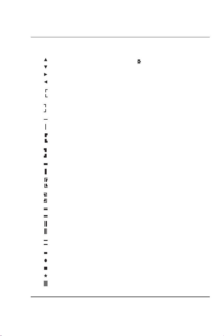
ASCII Code Table
Number
Char. Dec. Hex
0 00H
1 01H
2 02H
3 03H
4 04H
5 05H
6 06H
7 07H
8 08H
9 09H
10 0AH
11 0BH
12 0CH
13 0DH
14 0EH
15 0FH
16 10H
17 11H
18 12H
19 13H
20 14H
21 15H
22 16H
23 17H
24 18H
25 19H
26 1AH
27 1BH
28 1CH
29 1DH
30 1EH
Number
Char. Dec. Hex
31 1FH
<space> 32 20H
! 33 21H
" 34 22H
# 35 23H
$ 36 24H
% 37 25H
& 38 26H
' 39 27H
( 40 28H
) 41 29H
*422AH
+432BH
,442CH
-452DH
.462EH
/ 47 2FH
0 48 30H
1 49 31H
2 50 32H
3 51 33H
4 52 34H
5 53 35H
6 54 36H
7 55 37H
8 56 38H
9 57 39H
:583AH
;593BH
<603CH
=613DH
55 MCG-3 Color Micro Character Generator
Page 57

Number
Char. Dec. Hex
>623EH
? 63 3FH
@ 64 40H
A 65 41H
B 66 42H
C 67 43H
D 68 44H
E 69 45H
F 70 46H
G 71 47H
H 72 48H
I 73 49H
J744AH
K754BH
L764CH
M774DH
N784EH
O 79 4FH
P 80 50H
Q 81 51H
R 82 52H
S 83 53H
T 84 54H
U 85 55H
V 86 56H
W 87 57H
X 88 58H
Y 89 59H
Z905AH
[915BH
\925CH
|935DH
^945EH
Number
Char. Dec. Hex
_ 95 5FH
` 96 60H
a 97 61H
b 98 62H
c 99 63H
d 100 64H
e 101 65H
f 102 66H
g 103 67H
h 104 68H
i 105 69H
j 106 6AH
k 107 6BH
l 108 6CH
m 109 6DH
n 110 6EH
o 111 6FH
p 112 70H
q 113 71H
r 114 72H
s 115 73H
t 116 74H
u 117 75H
v 118 76H
w 119 77H
x 120 78H
y 121 79H
z 122 7AH
123 7BH
124 7CH
125 7DH
126 7EH
127 7FH
56 MCG-3 Color Micro Character Generator
Page 58
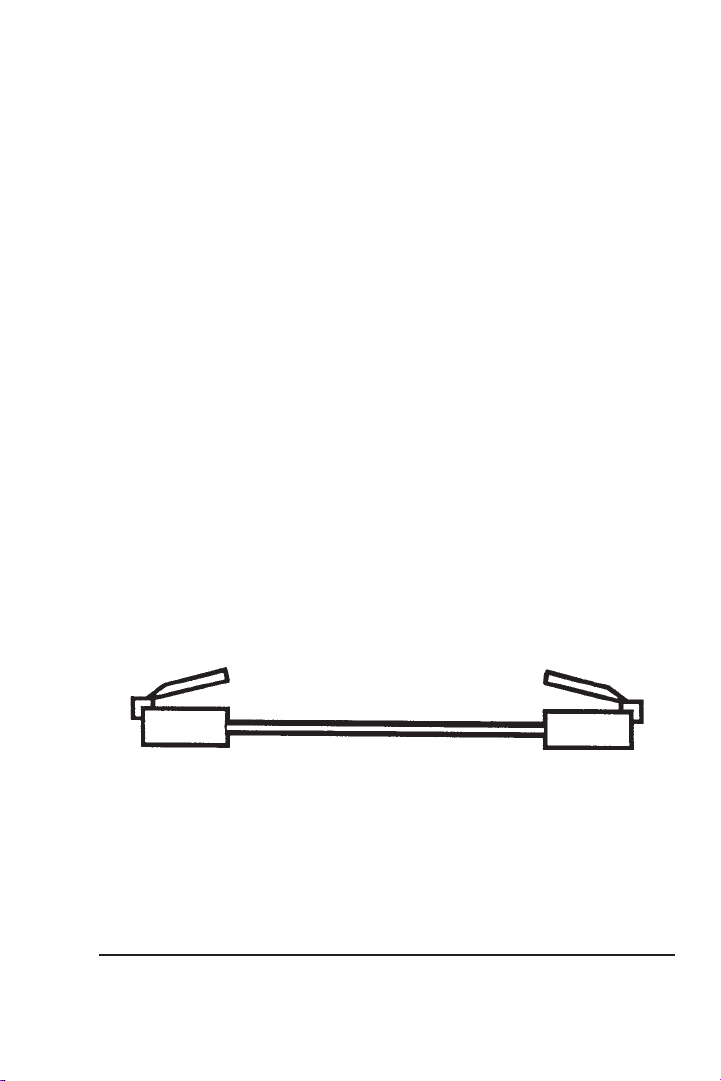
Figure 1: RJ11 Cable
57 MCG-3 Color Micro Character Generator
Page 59
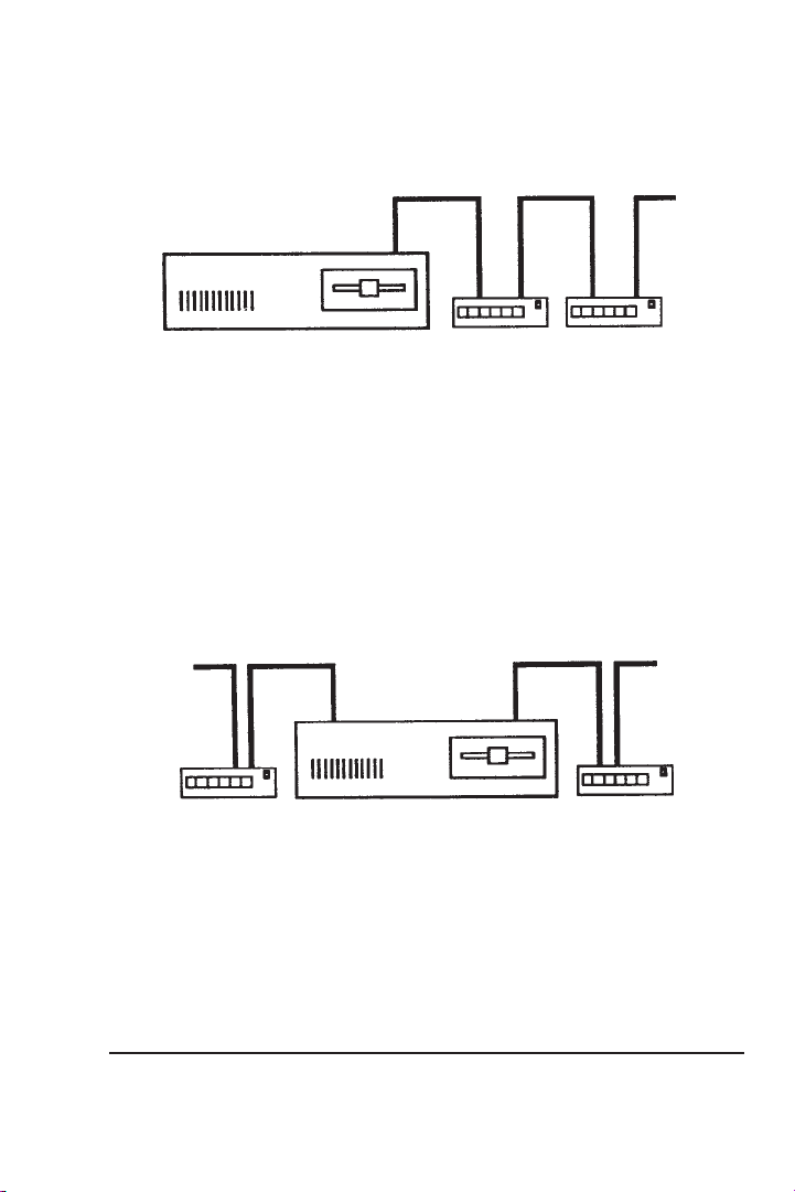
Comm Port
To Next Unit
Computer
MCG-3
Figure 2: Connecting MCG-3 to Serial Port
To Next Unit
MCG-3
Port 1
Computer
Port 2
Figure 3: Using Two Serial Ports
MCG-3
To Next Unit
MCG-3
58 MCG-3 Color Micro Character Generator
Page 60

RTC ADDENDUM FOR MCG-3
Introduction:
The RTC (Real Time Clock) option for the MCG-3 allows the MCG-3
to maintain the date and time of day, and displays these on the video
display. Time keeping is battery backed so the RTC will maintain time
and date information when power to the unit is off. The RTC maintains
date information as follows: month, date, and year. Leap year is
detected and corrected for on leap years. For time information the RTC
maintains hours, minutes, seconds and AM/PM status. The RTC will
work in miliary time (24 hour format) or standard time (12 hour
format).
Installation:
The RTC option is a small printed circuit board that installs on the
inside of the MCG-3. Proceed as follows:
1. Turn off the power to the MCG-3.
2. Remove the two screws on the face of the unit.
3. Remove the front panel.
4. Slide the top cover forward and remove.
5. Locate the lithium battery. It is positioned towards the front of
the unit, it is silver, about the size of a quarter, and is sitting in a
black holder. Directly behind the lithium battery (looking from
the front of the unit) is a black connector with 20 holes. This is
the connector for the RTC.
6. Remove the RTC board from its plastic page. Note, to avoid
damaging the RTC and the MCG-3 by static electricity, be sure
to electrically discharge yourself before removing the RTC
board from its bag.
7. With the power off, insert the RTC into the black 20 hole
connector, long end toward the rear of the MCG-3. (You should
still be able to see the lithium battery after the RTC is installed.)
59 MCG-3 Color Micro Character Generator
Page 61

Be sure that none of the pins bend, and that all of the pins and
connector holes line up, assuring that there is no misalignment.
8. Reassemble the unit being careful not to over tighten the
screws. (Do not tighten more than 1/8 turn past seated)
Setting the RTC (Real Time Clock):
RCG-3: Set the RTC using the remote commands
Set Time (ST)Set Time (ST)
Set Time (ST).
Set Time (ST)Set Time (ST)
MCG-3: The RTC must be set to the proper time/date. Proceed as
follows: Press and hold the PLUS button of the MCG-3 unit while
turning on the power switch. The screen should flash
RR
TT
C SC S
ET TET T
O ZO Z
EE
followed by
MCG-3 found the RTC and that the RTC was installed properly. If you
don’t get this message then the RTC was not properly installed – go to
the beginning of this section and make sure that you did everything
correctly.
R
T
C S
ET T
RR
TT
C SC S
ET TET T
RORO
O Z
E
RO. This message indicates that the
O ZO Z
EE
RORO
Set Date (SSet Date (S
Set Date (S
Set Date (SSet Date (S
RR
TT
R
T
RR
TT
C IC I
C I
C IC I
NN
N
NN
D)D)
D) and
D)D)
STST
AA
ST
A
STST
AA
LLELLE
LLE
LLELLE
Setting the Time and Date:
UU
TT
II
LILI
TT
Y MY M
EE
NN
Go the
U
T
I
LI
T
UU
MINUS keys set
AA
MM
time,
A
M
AA
MM
hours, minutes, and the date. To exit press either the MENU or
DISPLAY key. Upon exiting, the seconds will be set to
RTC will start (when in the setting mode the RTC is stopped).
Y M
TT
II
LILI
TT
Y MY M
//
PP
MM
//
/
P
M
/
M
//
PP
MM
//
UU
E
N
U and select
EE
NN
UU
AA
MM
//
PP
MM
A
M
/
P
M or
AA
MM
//
PP
MM
MM
TT
T must be set first. Move to the other items to set
MM
TT
SS
ET CET C
LL
OO
CC
S
ET C
SS
ET CET C
MM
TT
M
T for military time. Note, in setting the
MM
TT
KK
L
O
C
K. Using the PLUS or
LL
OO
CC
KK
0000
00 and the
0000
Turning on the Time and Date Display:
SS
CC
RR
EE
EE
N CN C
OO
NN
TT
RORO
L ML M
EE
NN
Go to the
The items for time and date display position are self explanatory,
however the items
explanation.
TT
II
T
I
TT
II
MM
M
MM
E FOE FO
E FO
E FOE FO
S
C
R
E
E
N C
O
N
T
II
I
II
M
OO
MM
MM
NN
TT
E FOE FO
E FO
E FOE FO
RO
RORO
RR
R
RR
SS
CC
RR
EE
EE
N CN C
TT
T
TT
RR
MM
AA
TT
R
M
A
T sets the format for which the time of day is displayed.
RR
MM
AA
TT
L M
L ML M
MM
M
MM
AA
A
AA
UU
E
N
U and select
EE
NN
UU
TT
DD
T and
D
TT
DD
II
I
II
SS
S
SS
P STP ST
P ST
P STP ST
CC
LL
OO
CC
K DK D
C
L
O
C
K D
CC
LL
OO
CC
K DK D
AA
TT
UU
SS
A
T
U
S will need some
AA
TT
UU
SS
II
SS
PP
LALA
YY
I
S
P
LA
Y.
II
SS
PP
LALA
YY
DD
D
DD
60 MCG-3 Color Micro Character Generator
Page 62

If set for 1, only hours and minutes are displayed (
AA
MM
//
PP
an
minutes, and seconds are displayed (
DD
II
D
I
DD
II
through with the PLUS or MINUS keys produces:
only,
OO
FF
O
F
OO
FF
Note that
DD
II
D
I
DD
II
to have a different setup for each page. Issuing a
will reset these items.
MM
A
M
/
P
M indicator is displayed (
AA
MM
//
PP
MM
SS
PP
LALA
Y STY ST
AA
TT
UU
S
P
LA
Y ST
SS
PP
LALA
Y STY ST
DD
D for Date display only,
DD
FF
F to turn off both the Time and Date display.
FF
TT
T
TT
SS
PP
LALA
Y STY ST
S
P
LA
Y ST
SS
PP
LALA
Y STY ST
SS
A
T
U
S turns the Time and Date display On or Off. Cycling
AA
TT
UU
SS
II
MM
E PE P
OO
SS
II
TT
II
OO
I
M
E P
O
II
MM
E PE P
OO
AA
TT
UU
SS
A
T
U
S are stored on a page by page basis, so it is possible
AA
TT
UU
SS
NN
S
I
T
I
O
N,
SS
II
TT
II
OO
NN
11
2:59 A2:59 A
1
2:59 A
11
2:59 A2:59 A
T&DT&D
T&D for both Time and Date display, and
T&DT&D
DD
AA
TT
E PE P
D
A
T
E P
DD
AA
TT
E PE P
MM
M). If set for 3, then hours,
MM
11
2:59:592:59:59
1
2:59:59).
11
2:59:592:59:59
OO
SS
II
TT
II
OO
NN
O
S
I
OO
SS
II
TT
T
I
O
N,
T
TT
II
OO
NN
TT
MM
M
MM
11
2:592:59
1
2:59). If set for 2,
11
2:592:59
TT
T for Time display
TT
II
MM
E FOE FO
RR
MM
AA
I
II
M
MM
AA
A
AA
E FO
E FOE FO
STST
ST
STST
EE
E
EE
R
RR
R RR R
R R
R RR R
M
MM
A
AA
EE
SS
E
S
EE
SS
TT
T and
TT
ETET
ET
ETET
61 MCG-3 Color Micro Character Generator
Page 63

MM
AA
STST
EE
R RR R
EE
SS
NOTES ON
MM
AA
The
MCG-3 to factory defaults as follows (for all 10 pages of memory):
With the RTC installed:
The
POWER LED condition, and may be needed after replacing the
Lithium battery. If, after replacing the battery, improper operation is
observed, then
MM
M
MM
setting. It does not erase the text pages. For the MCG-3, if you want to
erase all the pages, use
CC
C
CC
To clear all pages in the RCG-3, use the
STST
M
A
ST
MM
AA
STST
Character size: Smallest.
Display position: Centered.
Background: Black on.
Baud rate: 9600 baud.
Device ID: 01.
Clock display: OFF.
Date display position horizontal 04, vertical 09.
Time display position horizontal 13, vertical 09.
Time and date display status OFF.
Time format set to #3 (seconds display).
MM
AA
STST
M
A
ST
MM
AA
STST
AA
STST
EE
R RR R
A
ST
E
R R
AA
STST
EE
R RR R
OO
NN
TT
RORO
O
N
T
RO
OO
NN
TT
RORO
M
A
ST
E
MM
EE
R RR R
EE
SS
E
R R
E
S
EE
R RR R
EE
SS
EE
R RR R
EE
SS
E
R R
E
S
EE
R RR R
EE
SS
MM
AA
M
A
MM
AA
EE
SS
ETET
E
S
ET will set all page attributes to the factory default
EE
SS
ETET
L ML M
EE
NN
L M
L ML M
UU
E
N
U.
EE
NN
UU
R R
AA
STST
EE
R RR R
ETET
ET (found on the
ETET
ETET
ET can be used to recover from a FLASHING
ETET
STST
EE
R RR R
ST
E
R R
STST
EE
R RR R
CC
LEALEA
C
LEA
CC
LEALEA
ETET
E
S
ET:
EE
SS
ETET
UU
TT
II
LILI
TT
Y MY M
EE
NN
U
T
I
LI
T
UU
EE
SS
ETET
E
S
ET is required. Be warned that using the
EE
SS
ETET
R AR A
LL PLL P
R A
LL P
R AR A
LL PLL P
Y M
TT
II
LILI
TT
Y MY M
AGAG
EE
SS
AG
E
S on the
AGAG
EE
SS
Clear All (CClear All (C
Clear All (C
Clear All (CClear All (C
UU
E
N
U) resets the
EE
NN
UU
SS
CC
RR
EE
S
C
R
E
SS
CC
RR
EE
A)A)
A) command.
A)A)
EE
NN
E
N
EE
NN
62 MCG-3 Color Micro Character Generator
Page 64

TROUBLESHOOTING & FLASHING LED’s:
Your MCG-3 was designed to be reliable and easy to operate, and
features RAM Memory Error Detection. If an error in the battery
backed RAM memory should occur, (may be caused by the internal
battery being run down after a loss of AC power or by a glitch on the
AC power line) the POWER (green) LED will flash rapidly indicating
the error.
MM
AA
STST
EE
To recover from a flashing POWER LED condition issue a
RR
EE
SS
ETET
R
E
S
ET from the
RR
EE
SS
ETET
If the error was detected on power up, the video screen will be blanked
(so that possible garbage won’t be displayed). Pressing the MENU
button on the MCG-3 will automatically bring you to the
RR
EE
SS
ETET
R
E
S
ET selection on the
RR
EE
SS
ETET
MM
AA
The
flashing POWER LED condition is not detectable by remote control.
The reason for this is that the serial baud rate information is stored in
battery backed RAM, if the RAM contents have an error (the RAM
scrambled) then the baud information is likely to be wrong, in which
case serial communication would not be possible.
If your MCG-3 should not function as you think that it should, try
switching the power off and on again. Also you might try a
RR
R
RR
information will be reset. (See the section NOTES ON MASTER
RESET for more information.)
If you are experiencing trouble with remote control, check the
following:
STST
M
A
ST
MM
AA
STST
EE
SS
ETET
E
S
ET; however, be warned that character sizes, baud rate and other
EE
SS
ETET
Are the RS232 connectors plugged into the correct positions?
On the MCG-3? On the computer?
Does the baud rate your are using match the number set in the
utility menu?
Be sure that your PC is set for 8 data bits, 1 stop bit, and no parity.
EE
E
EE
UU
TT
II
LILI
TT
Y MY M
EE
NN
U
T
I
LI
T
Y M
TT
II
LILI
TT
Y MY M
UU
U
UU
SS
ETET
S
ET function is available from remote control, and a
SS
ETET
R RR R
R R
R RR R
UU
EE
E
EE
UU
E
N
U.
EE
NN
UU
TT
II
LILI
TT
Y MY M
EE
NN
T
I
LI
T
Y M
TT
II
LILI
TT
Y MY M
UU
E
N
U.
EE
NN
UU
MM
M
MM
AA
A
AA
MM
M
MM
M
MM
STST
ST
STST
RR
A
ST
E
R
AA
STST
EE
RR
EE
RR
E
R
EE
RR
AA
STST
EE
RR
A
ST
E
R
AA
STST
EE
RR
63 MCG-3 Color Micro Character Generator
Page 65

Be sure that the command(s) you are using are correct. (Look them
up in the COMMAND reference.)
In writing your own software, be sure to have a short delay between
RR
EAEA
DD
MM
EE
.D.D
OO
lines sent to the MCG-3. (See the
programs diskette for more information.)
If you are writing your own software, the MCG-3 may be reporting
errors that you don’t know about (your software may not read response
information or responses have been turned off). One thing that is highly
recommend in writing your own software, is to run a communications
program on the PC computer, execute the commands that you think
might be giving you trouble one by one, and see what responses
(errors) come from the MCG-3. Executing the commands one by one
also gives you a chance to see what exactly the MCG-3 does and/or
needs in your particular circumstance.
R
EA
D
M
RR
EAEA
DD
MM
CC
E
.D
O
C file on the example
EE
.D.D
OO
CC
64 MCG-3 Color Micro Character Generator
Page 66

ERROR MESSAGES:
The RS232 remote control ROM software has five error messages as
follows:
#1 Err#1 Err
or - Unknown commandor - Unknown command
#1 Err
or - Unknown command
#1 Err#1 Err
or - Unknown commandor - Unknown command
The MCG-3 did not understand the command you sent it. The
command is probably misspelled. Look up the command in the
Command Reference Section.
#2 Err#2 Err
or - Bad paror - Bad par
#2 Err
or - Bad par
#2 Err#2 Err
or - Bad paror - Bad par
One or more of the parameters in a command sent to the MCG-3 is
either too large, or too small, or of the wrong type (letters were sent
when the command wanted numbers or vice versa). Also this error can
occur if not enough or too many parameters are sent. Look up the
command in the Command Reference Section.
#3 Err#3 Err
or - Ror - R
#3 Err
or - R
#3 Err#3 Err
or - Ror - R
This error occurs when a RTC command is issued but the RTC option
is not installed.
#4 Err#4 Err
or - Command unaor - Command una
#4 Err
or - Command una
#4 Err#4 Err
or - Command unaor - Command una
This is an error that you are not likely to see. It is only produced with
custom ROM software and for special purposes at the factory.
ameterameter
ameter
ameterameter
eal time clock not installedeal time clock not installed
eal time clock not installed
eal time clock not installedeal time clock not installed
..
.
..
..
.
..
vailable.vailable.
vailable.
vailable.vailable.
..
.
..
#5 Err#5 Err
or - Comma missing or misplacedor - Comma missing or misplaced
#5 Err
or - Comma missing or misplaced
#5 Err#5 Err
or - Comma missing or misplacedor - Comma missing or misplaced
This error may be produced by not having enough commas in a
command sequence. In issuing a command there must be a comma
after the command to separate the command from its parameter(s).
65 MCG-3 Color Micro Character Generator
..
.
..
Page 67

Also if the command has more than one parameter a comma must
separate each parameter. This error may also be produced if a comma is
misplaced. This would be the case if a command wanted two digit
parameters and was issued with single digit parameters. Example: The
PP
page position command (
command sequence
command sequence
PP
P
P) needs two digit parameters. The
PP
PP
PP
P,9,6P,9,6
P
P,9,6 would produce an error, while the
PP
P,9,6P,9,6
PP
P,0P,0
9,09,0
P
PP
P,0
P,0P,0
66
9,0
6 would not.
9,09,0
66
66 MCG-3 Color Micro Character Generator
Page 68

BATTERY REPLACEMENT:
Your MCG-3 uses a Lithium watch battery (BR2325 or equivalent).
This battery should last 8 to 10 years. Battery replacement is indicated
by one or more of the following:
1. A “flashing power LED” condition whenever the unit is
powered up.
2. Time and date (with the RTC option) and buffer information is
not correctly maintained when power is off for any length of
time.
3. Baud rate and other settings not correctly maintained when
power is off.
If you take care in replacing the battery, with the Power On, then none
of the stored data will be lost.
To replace the battery, proceed as follows:
1. Remove the two screws on the face of the unit.
2. Remove the front cover panel.
3. Slide the top cover forward and remove.
4. The battery is silver, about the size of a quarter, and is sitting in
a black holder. Using a small screwdriver, gently remove the
battery, being VERY careful not to over bend the metal tab
holding the battery in place.
5. Locate the plus symbol (+) on the new battery and insert the
new battery plus (+) side up. BE VERY CERTAIN THAT THE
PLUS (+) SIDE IS UP.
6. Reassemble the unit being careful not to over tighten the
screws. (Do not tighten more than 1/8 turn past seated) The
battery may be replaced with the power on to maintain the
buffer data, and date and time (with the RTC option).
67 MCG-3 Color Micro Character Generator
Page 69

SPECIFICATIONS:
Power: 12 to 15 volts DC at 300mA (Polarity insensitive) or via 120
Vac wall module.
Size: 5.6W x 1.5H x 7.3D inches.
Video: Input - 1 volt PP composite terminated in 75 ohms.
Output - 1 volt PP composite with text overlay (short circuit
protected).
Keyer: Internal keyer (overlay).
Background and Character color: selectable from seven color palette
or transparent.
Character Size: 16 height and width combinations, as follows:
Height 1 - 28 scan lines
Height 2 - 58 scan lines
Height 3 - 84 scan lines
Height 4 - 114 scan lines
Width 1 - 24 characters per line
Width 2 - 12 characters per line
Width 3 - 8 characters per line
Width 4 - 6 characters per line
Selectable background and blink modes.
Storage: 10 pages of 240 characters each (Battery backed).
Remote control:
May be remotely controlled or function as a stand-alone unit.
Remote control via RS232 link to PC computer.
Simple two letter remote control commands.
Units may be “daisy chained” to form a network controlled by
one PC computer.
Uses inexpensive RJ11 (telephone) cable.
Accessories:
RS232 to RJ11 adapter
3 foot RJ11 cable
Remote control example programs diskette
User manual
120Vac wall adapter
Options:
Real Time Clock (RTC) - Maintains time and date, battery backed.
68 MCG-3 Color Micro Character Generator
Page 70
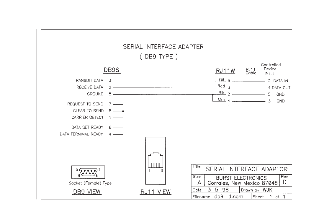
69 MCG-3 Color Micro Character Generator
Page 71
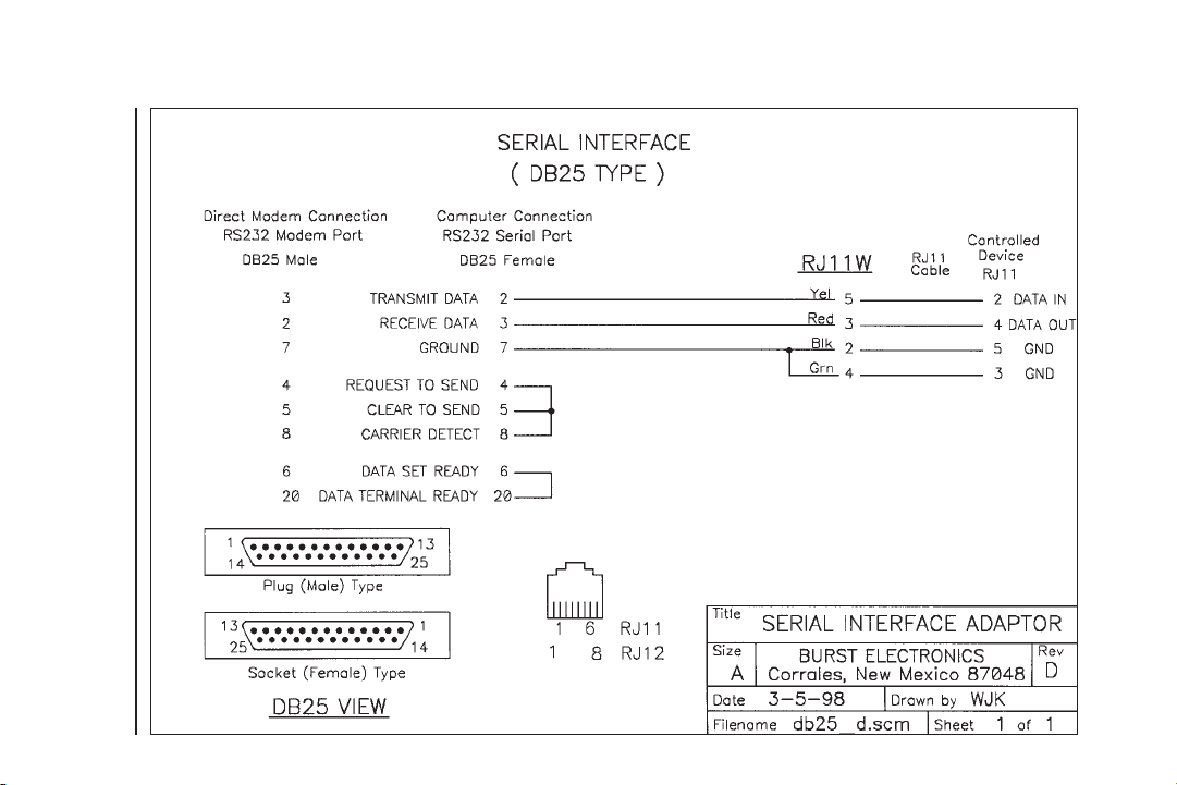
70 MCG-3 Color Micro Character Generator
 Loading...