

Page 1

GPI-10,
GPI-10K
General Purpose Interface
(GPI) to RS232 Converter,
10 Channel
Manual Version 3.01
BURST ELECTRONICS INC
ALBUQUERQUE, NM 87109 USA
(505) 898-1455 VOICE
Made in USA
(505) 890-8926 TECH SUPPORT
(505) 898-0159 FAX
www.burstelectronics.com
Hardware, software and manual copyright by Burst Electronics. All rights reserved. No part
of this publication may be reproduced or distributed in any form or by any means without the
written permission of Burst Electronics.
Page 2

GPI to RS232 Converter
Introduction
Congratulations on your purchase of the Burst Electronics
model GPI-10. This product con verts a momentary contact
closure (factory default) or momentary contact open (user
selectable internal jumper) to a RS232 stream of data. The
GPI-10 was originally designed to command the Burst
Electronics MCG -2 (or MCG-3) Micro Character Generator
to overlay, on to video, each of its 10 pages stored in
memory. Another option is to have the GPI-10 factory
programmed with RS232 dat a that you provide (contact
Burst Electronics for details and pricing).
The GPI-10 has 11 screw terminal connectors on the bac k.
One of these connectors, called COM (meaning common),
is used with each of the other connectors through a contact
closure suc h as a momentary push button switch to create
the trigger. Activation of the push button switch is all that is
required to trans mit the preprogrammed data. The trigger
only needs to be active for 5mS (0.005 seconds). If a
trigger is active while a second trigger is activated, no data
will be transmitted. You must release the first trigger before
activating the next trigger.
There is also a model with a keypad on the top of the unit
(GPI-10K). Each of the numbered pushbuttons (0-9), when
pressed, will stream RS232 data in the same manner as
stated above. The zero (0) key is used as number 10. The
pound (#) key and the asterix (*) key are not used.
The RS232 connector is RJ11 style (standard telephone
plug). The RJ11 cable used is also a standard 4 conduc tor
GPI -10 GPI to RS232 Converter 2
Page 3

telephone cable. If you are using the GPI-10 to
communicate to a PC computer, you will need a Null
Modem Adapter (included with the GPI-10). The Null
Modem Adapter converts DB9 (standard computer serial
port) to RJ11.
If you use normally closed contacts, vs. normally open
contacts, to command the GPI-10, you will need to change
the internal jumper (factory default is for normally open
contacts). To select normally closed triggering, remove the
front panel of the GPI-10 and slide the top cover off.
Remove the shunt at W1 for normally closed trigger.
Replace the shunt if normally open contacts are going to be
used. (Note: if normally closed is selected, the front panel
LEDs corresponding to each contact will remain lit until you
perform an open trigger). Burst Electronics’ default for this
selection has the shunt installed (normally open operation).
When using normally closed contacts, use only the terminal
connectors on the rear of the unit, as the keypad is
configured for Normally Open operation only.
The GPI-10 communicates at 9600 baud, 8 data bits, No
stop bits, and 1 parity bit (9600,8,N,1). There is no flow
control associated with this device.
MCG Operation
Connect the supplied RJ11 cable between the GPI-10 and
the “Host” input of the MCG. Apply appropriate power to the
GPI-10 and the MCG (consult your users manual for
specifications). Each numbered output of the GPI-10
corresponds to the same numbered page of the MCG
(keypad 1-9 displays pages 1-9 and keypad zero (0)
displays page 10). As you trigger each of the GPI contacts,
the appropriate page is displayed from the MCG. Example:
If input terminal 5 is triggered (5 on the keypad), then page
5 in the MCG’s memory will be displayed.
GPI -10 GPI to RS232 Converter 3
Page 4

The data sent in this example is:
Data Description
WK,01 Wake up MCG
DP,5 Display Page 5
MX,1 Turn Mixer On
SP Put MCG to sleep
Custom Programming of the GPI-10
If you are familiar with the programming of the PIC16C5x
family of controllers, contact Burst Electronics for advice on
programming and sample of the code that is programmed
into the GPI-10’s PIC.
GPI -10 GPI to RS232 Converter 4
Page 5

SPECIFICATIONS
Input: Either normally open or
normally closed (jumper
selectable)
or Keypad (normally
open only)
Input Duration: 50mS minimum
Output Data: RS232, 9600,8,N,1,
Flow: None
GPI Connector: 11 Screw terminals
RS232 Connector: RJ11
Size: 4.2”W x 1.5”H x 5.5”D
Power Requirements: 11 to 15Vdc @ 100mA,
center pin negative
Power Supply (included): 12Vdc @ 500mA,
center pin negative
Rack Mount kit: RM-334 - can hold one
GPI-10 and two MCG’s
RM-344 - can hold two
GPI-10’s and one MCG
RM-4 - can hold four
GPI-10’s
GPI -10 GPI to RS232 Converter 5
Page 6
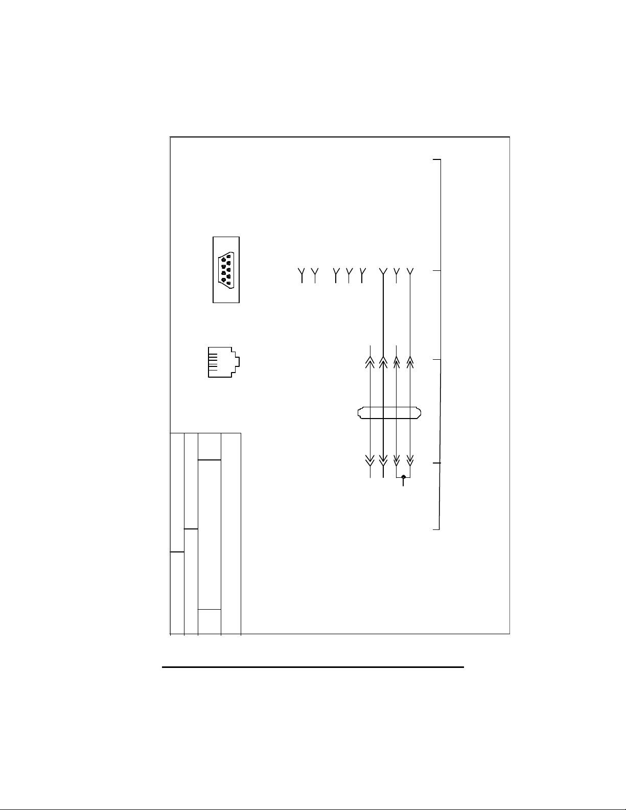
Controlled Device
Data Terminal Ready
Data Set Ready
Request to Send
Carrier Detect
Clear to Send
Transmit Data
Receive Data
Socket (Female) Type
9 6
Ground
DB9
4
6
1
8
752
15
RJ11
61
Title
A
Null Adapter for GPI-10
Corrales, New Mexico 87048
db9nul_b.scm 11
BURST ELECTRONICS
3
Blk
Yel
4
2
RJ11DB9S
3
5
RJ11 CableNull Adapter
RJ11
4
3
Data Out
NC
2
5
GPI-10
Ground
Drawn byDate
Sheet ofFilename
WJK2.6.02
RevSize
B
GPI -10 GPI to RS232 Converter 6
Page 7

NOTES
GPI -10 GPI to RS232 Converter 7
Page 8

GPI -10 GPI to RS232 Converter
 Loading...