

Page 1
DSR4x1
4-Input and 8- Input
HD/SD Video Switchers with
DSR8x1
Analog Reference Video Input
Manual Version 1.01
BURST ELECTRONICS INC
ALBUQUERQUE, NM 87109 USA
(505) 898-1455 VOICE
(505) 890-8926 Tech Support
(505) 898-0159 FAX
www.burstelectronics.com
Hardware, software and manual copyright by Burst Electronics. All rights reserved. No part
of this publication may be reproduced or distributed in any form or by any means without the
written permission of Burst Electronics.
Made in USA
Page 2
Four/Eight Input HD/SD SDI Switcher
Introduction
Congratulations on your purchase of the DSR4x1/
DSR8x1 HD/SD SDI Video Switcher with Analog
Reference Input. This manual will explain the various
functions of these models (as well as operational use
of th e RS232 and DTMF options). Unless otherwise
stated, all functions of the DSR4x1 are identical to that
of the DSR8x1.
Overview
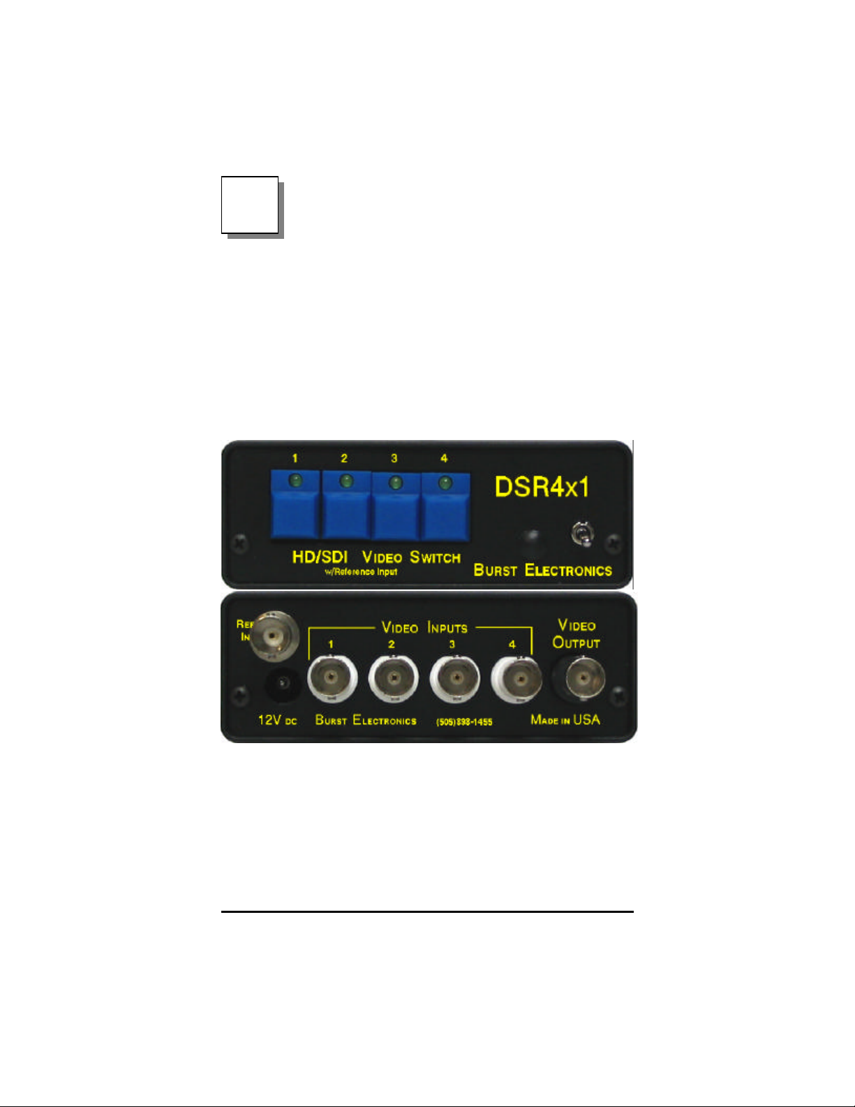
The model DSR4x1 is a four (4) input, full bandwidth
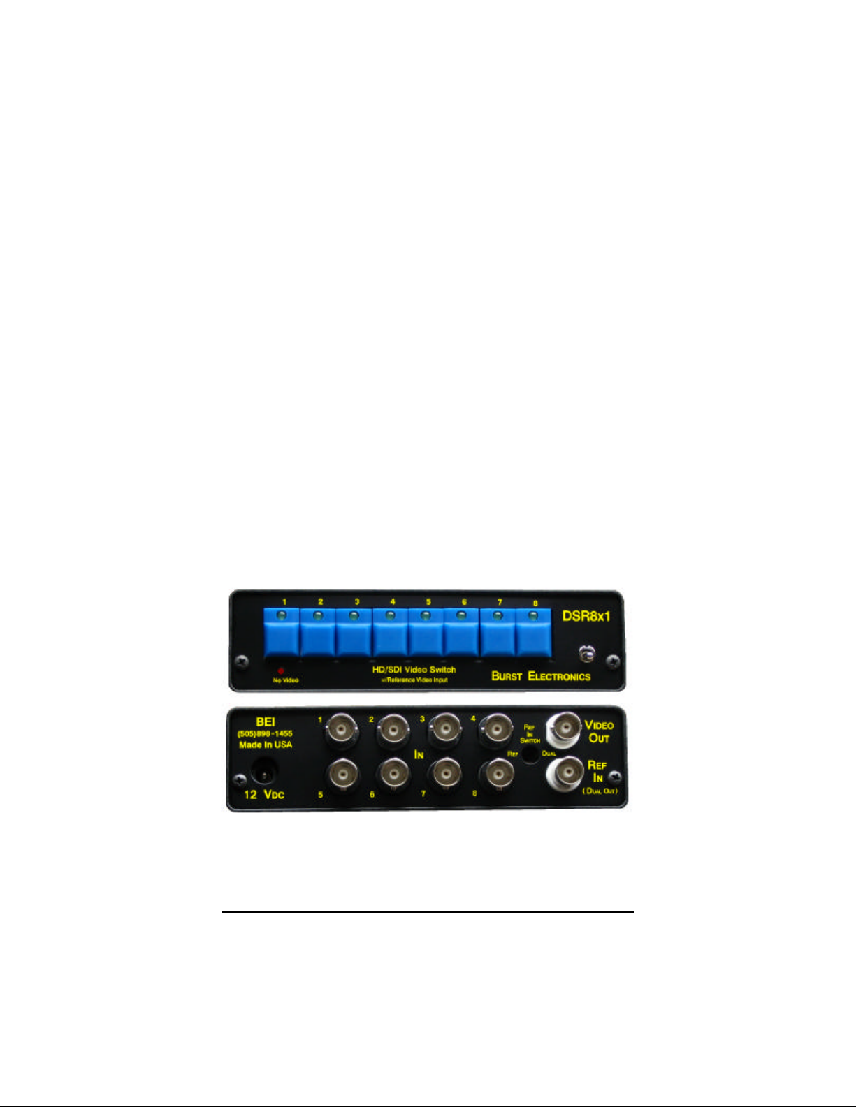
digital HD and SDI switcher (DSR8x1 is an eight (8)
channel switcher). The front panel switches are
labeled to correspond with the appropriate video input,
an LED indicates the currently selected active
DSR8x1 & DSR4x1 HD/SD SDI Video Switcher 2
Page 3
channel. If an analog video input (composite sync or
tri-level sync) is present on the Ref Input port, then
clean switching betw een video sources can be
accomplished when your digital sources are
synchronous with the analog video.
Operation
Simply depress one of the front panel switches to
select a video input. The button you have pressed will
illuminate an embedded LED to indicat e the channel
is selected. If an analog video signal (black burst or trilevel sync) is connected to the Ref Input port, the
digital video signal will switch during the vertical
interval cycle of the reference video. This change
takes place at approximately line 10 of the analog
video signal. It is strongly suggested that your digital
video sources also receive the same analog reference
video signal. As with analog vertical interval video
switchers, your digital video sources should be
genlocked.
On the rear panel of the DSR8x1, the Ref Input port
can be configured as a secondary video output. To
DSR8x1 & DSR4x1 HD/SD SDI Video Switcher 3
Page 4

change to a dual output you will need only flip the
toggle switch, that is recessed in the rear panel, from
Ref to Dual. This will negate clean switching between
video inputs because there will no longer be an analog
video signal (or tri-level sync) for th e switcher to
reference.
Power
These units are powered from an external 12Vdc
source. Polarity of the included power supply is center
positive, but the units can also operate with center
negative. Only use a DC power supply, do not use an
AC power source. You may damage the unit and will
void all warranties.
Remote Control via RS232 (R Version)
An option that can be installed by the factory is RS232
control via computer. The unit is fitted with a proprietary
connector and shipped with a serial port adapter and
RJ11 cable. The unit communicates at a selectable
baud rate. This product default baud rate is 2400 8N1.
To change this baud rate, remove the front panel and
slide the top cover off. Directly behind the front panel
keyboard switches is a small 4-pole piano switch.
Change switch #1 and #2 in the following manor to
configure the baud rate.
SW#1 Open, SW#2 Open = 2400 Baud
SW#1 Closed, SW#2 Closed = 9600 Baud
SW#1 Open, SW#2 Closed = 19.2k Baud
SW#1 Closed, SW#2 Open = 19.2k Baud
NOTE: Leave SW#3 and SW#4 in the OPEN position.
Closing these switches will stop the unit from
transmitting status commands to the computer.
Any ter minal emulator (i.e. Windows Hyperterminal or
DSR8x1 & DSR4x1 HD/SD SDI Video Switcher 4
Page 5

Procomm) is all that is required to communicate with
the switcher. The command set for the DSR4x1
consists of a two character command followed by a
carriage return (<CR>). The first character can be
either upper or lower case.
Status sent
Command Function to computer
V1<CR> Switches to Channel #1 (V1+)
V2<CR> Switches to Channel #2 (V2+)
V3<CR> Switches to Channel #3 (V3+)
V4<CR> Switches to Channel #4 (V4+)
The video switcher will also echo “V#” (where “#” is
the channel number currently selected) back to the
computer to indicate its status.
The command set for the DSR8x1 consists of a two
character command followed by a carriage return
(<CR>). The first chatacter can be either upper of
lower case.
Status sent
Command Function to computer
V1<CR> Switches to Channel #1 V1
V2<CR> Switches to Channel #2 V2
V3<CR> Switches to Channel #3 V3
V4<CR> Switches to Channel #4 V4
V5<CR> Switches to Channel #5 V5
V6<CR> Switches to Channel #6 V6
V7<CR> Switches to Channel #7 V7
V8<CR> Switches to Channel #8 V8
Active Input Switch Status
To determine which input is active, send the following
command;
AV<CR>
DSR8x1 & DSR4x1 HD/SD SDI Video Switcher 5
Page 6

The DSR switcher will respond with V# (where “#” is
the input channel currently selected).
RS232 Error Codes
Code Description
KE - Keyboard Error (invalid command sent)
KT - Keyboard Timeout (too long between keystrokes)
Remote Control via RC8x1 (DSR 8x1 opt
RC)
An optional remote control unit called the RC8x1 can
be mated with the DSR8x1. The RC8x1 is a small
enclosure with eight (8) illuminated switches that
commands the DSR8x1. This unit is powered by the
DSR8x1 through the included unwired control cable.
The DSR8x1 is fitted with a special locking connector
to counteract high vibration (such as ENG trucks or
helicopters). Operation of the RC8x1 is the same as
the DSR8x1, just depress the appropriate switch for
the input video channel you wish to select. The RC8x1
will brighten the depressed switch and will also
change the DSR8x1 front panel switch LED to the
selected input .
Remote Control via DTMF (DSR8x1 opt. T)
Another option that can be modified into the DSR8x1
is DTMF tone control. This option works with the audio
tones generated from a touchtone telephone system,
or a tone generator capable of creating DTMF tones.
A 3.5mm jack is installed on the rear panel to facilitate
interface with the tone generator that you provide.
The DSR8x1 is ID addressable by holding down one
of the front panel switches when you turn on power (i.
e. holding pushbutton #1 during power up will address
the unit as #1, holding pushbutton #6 during power up
DSR8x1 & DSR4x1 HD/SD SDI Video Switcher 6
Page 7

will address the unit as #6). After an ID is set the
DSR8x1 will flash the embedded LED beneath the
input channel number 5 times at power up. To
command the unit to switch, the unit ID and input
channel will need to be sent in the format of “UnitID #
Channel *”.
Example;
1#5* = Unit ID 1 will switch to Channel 5
6#2* = Unit ID 6 will switch to Channel 2
DSR8x1 & DSR4x1 HD/SD SDI Video Switcher 7
Page 8

Specifications
SDI Input Connectors: DSR8x1 – 8 BNC Input
DSR4x1 – 4 BNC Input
Supported SDI Input/Outputs:
SMPTE 292M, SM PTE 259M, SMPTE 344M
compliant, 143, 177, 270, 360, 540, 1483.5/
1485 Mbps, DVB-ASI at 270 Mbps
SDI Input Characteristics:
Levels (HD/SD SDI) – 25 to 1V p-p signal
level
Terminated – 75 ohms
DC offset permitted is: -0.5 to 2VDC
REF Connector:
1 – BN C
REF Input Characteristics:
Analog NTSC/PAL composite video
Analog HD Y channel with tri -level syncs
Terminated – 75 ohms
Level – 0.5 to 2V p-p
Switch Point:
With REF input – approximately line 10 of REF
input signal
No REFerence input – random switching
SDI Output Connectors:
2 – BNC (Differential Output of single output)
SDI Output Characteristics:
Levels (HD/SD SDI) – 800mV nominal
Re-clocked Jitter – HD 0.06 UI; SD 0.02UI
Matrix Configurations:
DSR8x1 – 8 inputs x 1 output
DSR4x1 – 4 inputs x 1 output
Inputs can be mixed standards
Local Controls:
4 or 8 momentary switches with LED indicators
for input select
Toggle ON/OFF switch
DSR8x1 & DSR4x1 HD/SD SDI Video Switcher 8
Page 9

Front Panel Indicators:
LED for standard detection (HD)
POWER LED
Remote Controls:
RS-232 Serial control; 8N1; 2400b, 9600b, or
19.2Kb (internal switch selectable) – OR
DTMF per ANSI T1.401-1988
Power Supply:
Unregulated 12Vdc @ 1A – OR
OPTIONAL Re gulated 5Vdc @ 1A
Power Draw:
12Vdc @ 650mA (7.8W)
OPTIONAL 5Vdc @ 650mA (3.25W)
Environmental:
0 to 98% humidity non-condensing
0 to 40C operating
-20 to 65C storage
Mechanical:
Dimensions
DSR8x1 - 5.6W x 1.5H x 7.3D (inches)
14.2W x 3.81H x 18.54D (cm)
DSR4x1 - 4.2W x 1.5H x 5.5D (inches)
10.67W x 3.81H x 13.97 (cm)
Weight
DSR8x1 - 1.5 (lbs)
0.68 (kg)
DSR4x1 - 1 (lbs)
0.45 (kg)
DSR8x1 & DSR4x1 HD/SD SDI Video Switcher 9
Page 10

DSR8x1 & DSR4x1 HD/SD SDI Video Switcher 10 DSR8x1 & DSR4x1 HD/SD SDI Video Switcher 11
Page 11

Page 12

DSR8x1 & DSR4x1 HD/SD SDI Video Switcher 12
 Loading...