

Page 1
AS8x8
Crosspoint Audio
Switch 8 by 8 Stereo
Manual Version 2.01
BURST ELECTRONICS INC
ALBUQUERQUE, NM 87109 USA
(505) 898-1455 VOICE
Made in USA
(505) 898-0159 FAX
www.burstelectronics.com
Hardware, software and manual copyright by Burst Electronics. All rights reserved. No part
of this publication may be reproduced or distributed in any form or by any means without the
written permission of Burst Electronics.
Page 2
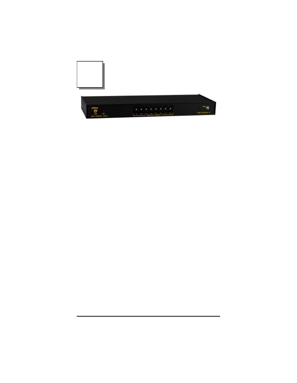
AS8x8
Crosspoint Audio Switch
8 by 8 Configuration
Product description
The AS8x8 Audio Crosspoint Switch is a digitally
controlled matrix of 64 T -Switches that can connect
any one of eight stereo audio inputs to any, or all, of
eight audio outputs. The switch matrix utilizes
monolithic, CMOS matrix IC's to achieve minimal
crosstalk.
The AS8x8 can be manually controlled using the front
panel controls or remotely controlled via a standard,
asynchronous RS232 Serial Interface.
The eight audio inputs are fu lly buffered.
The eight audio outputs are driven by high quality
stable audio amplifiers that are capable of driving 600
Ohm lo ads.
The system features a unique and simple
programming operation which allows the user to
specify various operating parameters, i.e., mode of
operation, baud rate, unit ID code, etc. Programmed
information is stored in an internal EEPROM to
prevent inadvertent loss of data caused by the loss of
power.
AS8x8 Audio Routing Switch 1
Page 3
Power Supply
The unit is shipped with a wall mount DC power
supply rated at 12 volts, 500 mA. Other suitable
power supplies in t he range of 9 to 15 volts may also
be used. The unit has an internal bridge rectifier on
the power supply input so that the user need not be
concerned with the polarity of the power connector
being used.
Audio Connections
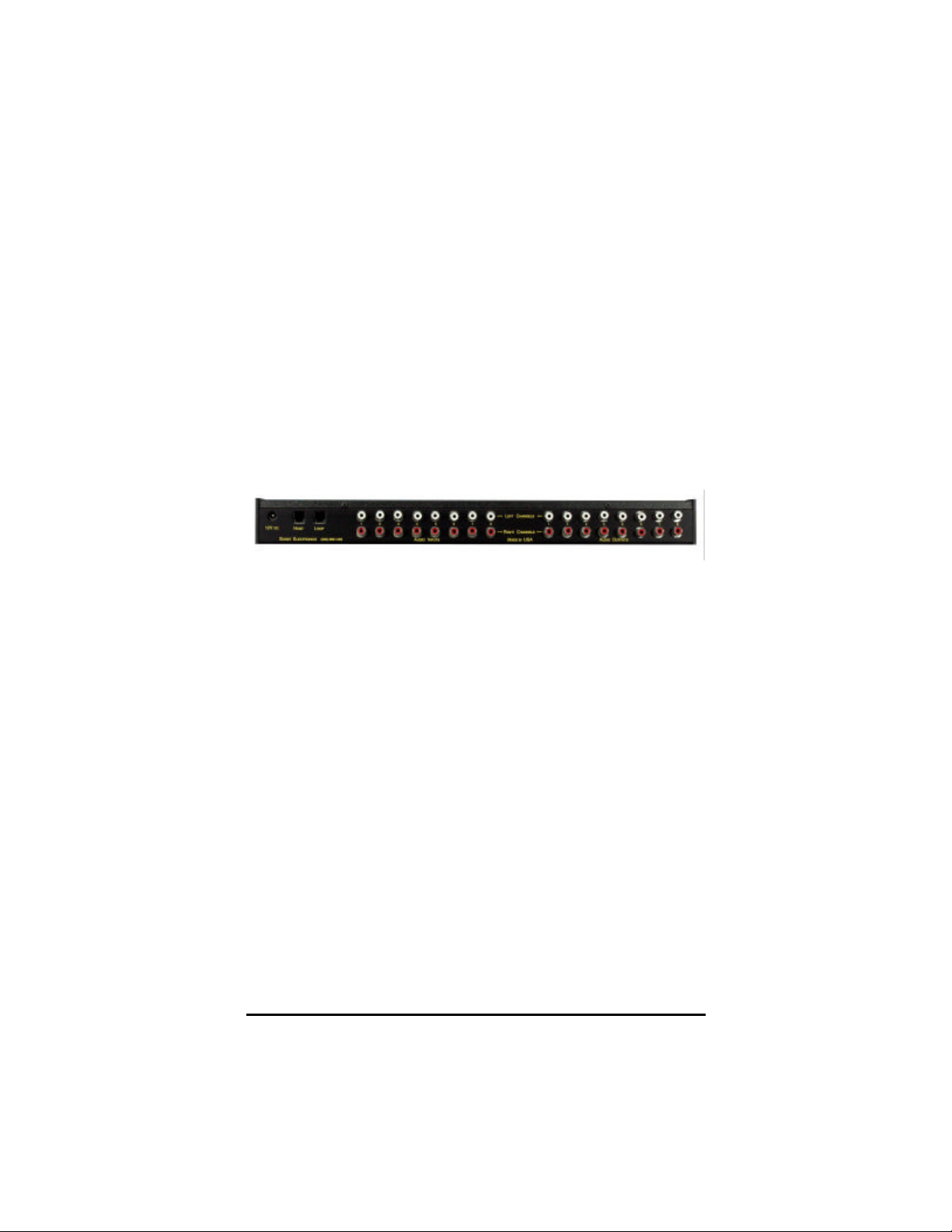
The eight stereo audio inputs and eight stereo audio
outputs are located on the rear panel of the device.
The connectors are phono (RCA) style unbalanced.
Serial Interface
The RS232 Interface connections use RJ11 type
connectors located on the rear panel. The unit is
supplied with a cable adapter for connecting the
system to standard DB9 Serial Comm Ports. The two
RJ11 connectors on the rear panel of the system are
labeled HOST, and LOOP. The cable adapter is
configured for connection to a standard DTE Serial
Interface common to most all personal computers.
Refer to the Appendix section, for detailed
information on the serial interface connections. For
systems employing a single AS8x8 unit, the serial
cable is connected to the rear panel RJ11 connector
labeled HOST. For systems using multiple AS8x8's,
the systems are "daisy-chained" by connecting the
LOOP connector of each unit to the HOST connector
of the next successive unit.
AS8x8 Audio Routing Switch 2
Page 4
System Configuration
Prior to operation, the unit must first be configured by
programming various operating parameters and
storing them in the internal EEPROM memory. The
unit is programmed with the following parameters.
1. Operating Mode
2. Serial Port Baud Rate
3. Unit Identification Code
Operating Mode
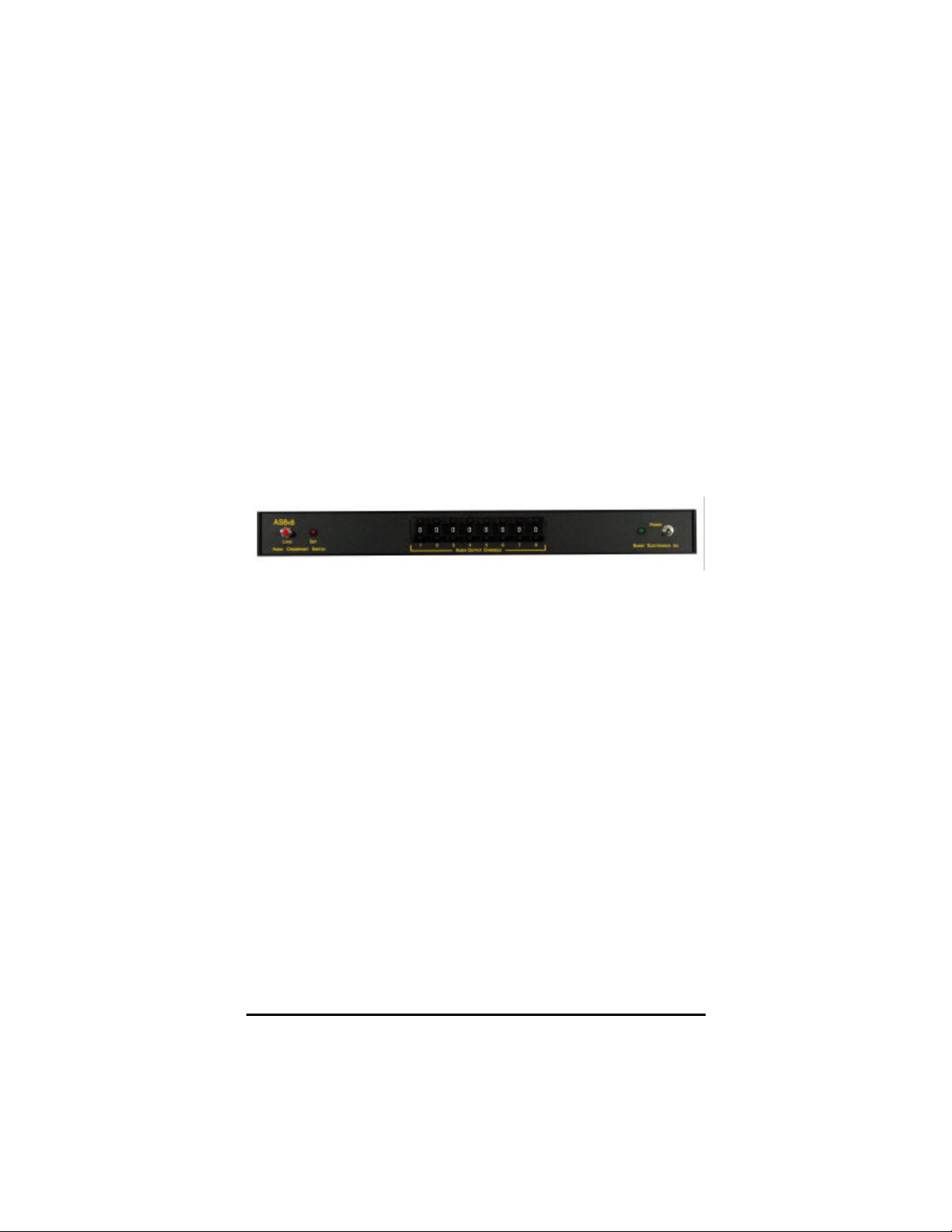
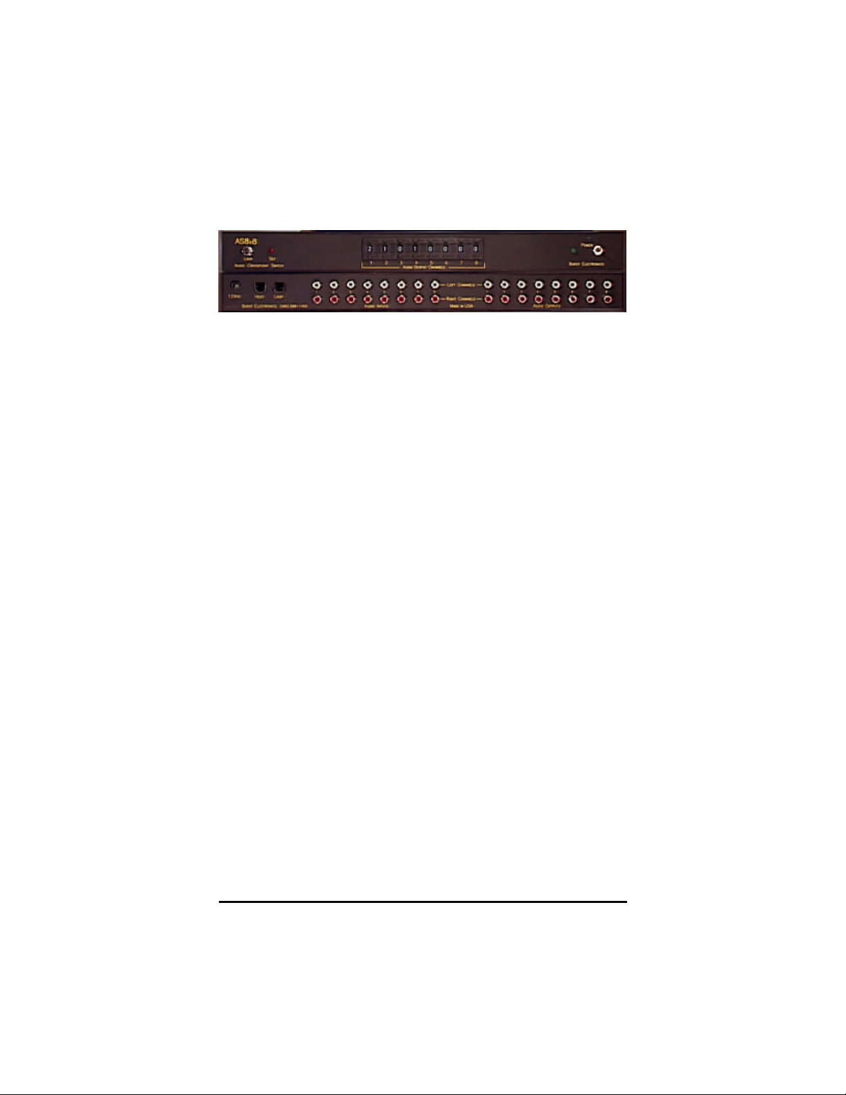
The operating mode is selected by setting the front
panel thumbwheel switch l abeled Audio Output
Channel 1. The unit supports two Manual Modes and
two Remote Modes. In Manual Mode, the unit
switches the au dio signals under control of the front
panel thumbwheel switches. In Remote Mode, all
audio switching is controlled by commands sent to
the unit using the RS232 interface.
The mode settings are as follows:
Mode 1: Scanned Manual Mode
In this mode, the fr ont panel thumbwheel switches
are continuously scanned for any changes. When a
change is detected, the unit automatically switches
the audio switch setting.
Mode 2: Triggered Manual Mode
AS8x8 Audio Routing Switch 3
Page 5

This mode is similar to the Scanned Manual Mode, in
that the unit continuously checks the front panel
switches for any change. When a change is detected,
the unit then waits for the operator to press the LOAD
pushbutton before switching the audio.
Mode 3: Single Unit Remote Mode
In this mode, all audio switching is accomplished by
sending commands via the RS232 Serial Interface.
See BAUD Rate for setting the communication
speed.
Mode 4: Multiple Unit Remote Mode
This mode is the same as Mode 3, but also supports
multiple units on the same RS232 interface. Each unit
must have a unique Unit Identification Code, and
requires address commands to be sent from the host
computer prior to any switching commands. See
BAUD Rate for setting the communication speed.
BAUD Rate
The front panel thumbwheel switch labeled Channel 2
is used to program the baud rate for the RS232
interface. The serial interface parameters are 1 stop
bit, 8 data bits, and no parity. The AS8x8 supports
the following baud rates:
Switch Setting BAUD Rate
1 9600
2 4800
3 2400
4 1200
5 600
6 300
7 150
AS8x8 Audio Routing Switch 4
Page 6

Unit Identification Code
The next two front panel thumbwheel switches
(Channels 3 and 4) are used to program the Unit
Identification Code. In a single unit system (Mode 3),
changes to these values are irrelevant. In multiple
unit remote configurations, thi s value can be any
number from 01 to 99, but care must be taken to
insure that all units have a unique ID code.
Programming
Programming the configuration information into
internal EEPROM is accomplished by first setting the
front panel thumbwheel switches (Channel 1-4) to the
desired setting. The unit is then powered up while
depressing the front panel LOAD pushbutton. Upon
power up, the internal microprocessor detects the
depression of the LOAD switch , and then programs
the internal EEPROM memory with th e selected
values. The unit will flash the front panel SET LED for
a few seconds to indicate that it is programming the
system EEPROM, and will then enter the operating
mode. The unit will now enter the appropriate
operating mode whenever it is powered up. The unit
can be reprogrammed any time the user desires, and
the internal EEPROM is rated for an excess of 10,000
write operations.
Operation
The following paragraphs detail the operating
procedures for each of the four operating modes that
can be programmed into the AS8x8 Audio Crosspoint
Switch.
Mode 1 (Scanned Manual Mode)
When operated in this mode, the user sets the front
AS8x8 Audio Routing Switch 5
Page 7

panel thumbwheel switch corresponding to the
specific output channel. Setting the thumbwheel
switch to the values of 1 through 8 will connect that
audio input to the specified output. Setting the
thumbwheel switch to a value of 0 or 9 will turn off the
output. When the unit detects a change on the front
panel thumbwheel switches, it will switch
immediately. In this mode the front panel SET LED is
always on, indicating that the audio outputs are
always corresponding with the thumbwheel settings.
Mode 2 (Triggered Manual Mode)
This mode is similar to the Scanned Manual Mode,
with one exception. When a change is detected, the
system will turn off the "SET" LED to indicate a
disparity between the thumbwheel switches, and the
actual audio signal routing. The unit then waits for the
operator to initiate the new selection by pressing the
front panel "LOAD" button. This mode prevents
erratic audio outputs caused by scrolling the
thumbwheel switches through the selections. Once
the "LOAD" button is pressed, the unit then sets the
new selection and then reactivates the "SET" LED to
indicate that the new selection has been activated.
Mode 3 (Single Unit Remote Mode)
In this mode, the unit is controlled exclusively by the
serial RS232 interface. Routing of the au dio signals is
accomplished by using a host computer to transmit
simple commands to set the audio outputs. The
following is a list of the commands used by the
AS8x8. Each command must be terminated by a
carriage return (hex 0D). All characters that are
transmitted to the unit are echoed back to the host
AS8x8 Audio Routing Switch 6
Page 8

computer.
Command Description
Sio (Set Input Output)
This command routes an input channel specified by i
to and output channel specified by o. The i and o
characters are single digit values from 0 to 8 (0 being
channel off). There are no spaces allowed. The
command must be followed by a carriage return. The
unit switches immediately after receiving the carriage
return.
R (READ)
This command causes the AS8x8 to transmit the
current settings of all 8 audio outputs to the host
computer. No carriage return is necessary.
L (LOCK)
When received , this command locks the current
audio setting to prevent changes. Once locked the
unit wi ll then ignore any subsequent SET commands,
and will display an appropriate error message. The
audio setting can still be viewed using the READ
command. The unit will stay in the locked mode until
as ESC (1B hex) code is received. No carriage return
is necessary.
M (MANUAL)
This command is used to place the unit in the
Triggered Manual Mode (Mode 2) from the Remote
Mode. Once init iated, the unit will remain in the
Triggered Manual Mode. To return to the remote
mode transmit an ESC (1B hex) to the unit. No
carriage return is necessary.
AS8x8 Audio Routing Switch 7
Page 9

Mode 4 (Multi Unit Remote Mode)
In this mode, several units are controlled exclusively
by the serial RS232 interface. Routing of the audio
signals is accomplished by using a host computer to
transmit simple commands to set the audio outputs.
Each unit to be controlled must be given a unique ID
address to allow the host computer to distinguish
which switcher is to be controlled. A user can use the
same ID address to control multiple AS8x8 switchers
simultaneously. The command structure for Mode 4 is
identical to that of Mode 3 with the following
exceptions.
Setting ID Address
As stated before, channel #1 sets the Mode of the
AS8x8 and channel #2 sets the baud rate. Channel 3
and channel 4 become the ID address for an AS8x8.
Set the Mode, Baudrate, and ID address, then hold
the LOAD button during power up to set the AS8x8
into Mode 4. You must use both Channel 3 and
Channel 4 to set the ID address. The range of ID
address supported with the AS8x8 is 01 to 99. As you
can see, ideally, nearly one hundred units can be
controlled in this manor. However, with the delays
involved with sending and receiving data through the
AS8x8s, only about ten (10) units can be connected
together on the same RS232 line.
WK,## (Wake Unit ID)
This command is the first command sent to an AS8x8
set to Mode 4. This command activates the
communication between the host computer and the
switcher. The syntax for this command is WK,##
(where ## is the unique ID address, a comma (,) is
AS8x8 Audio Routing Switch 8
Page 10

required between WK and ##, example; WK,01 will
wake up ID address 01). A carriage return is required
after this command is entered.
SP (Sleep)
This command is used to stop an AS8x8 from acting
upon commands that may be sent to a different ID
addressed AS8x8 connected to the same RS232 line.
A sleep command is a global command, this means
that the command will put all units connected to
“sleep”. No carriage return is necessary.
AS8x8 Audio Routing Switch 9
Page 11
Specifications
Audio Inputs
HiZ (100k) stereo unbalanced phono (RCA)
connectors
Level: 0 dBm (775 mV)
Audio Outputs
Level: 1V p-p, nominal
Impedance: 75 Ohm
Serial Interface
Standard RS232 (4 wire)
8 data bits, No parity bit, 1 stop bit (8,N,1)
Speeds: 150, 300, 600, 1200, 2400, 4800, 9600 Baud
Performance
Distortion: .03% THD
Headroom: +12 dB
Bandwidth: 10 Hz to 40 kHz ± 0.25 dB
S/N: 91 dBA
Electrical
Power Supply: 9-12 VDC @ 250 mA
Mechanical
Height: 1.75H x 16.5W x 6.0D inches
Rack Mount: RM-Ear
AS8x8 Audio Routing Switch 10
Page 12

Notes
 Loading...