

Page 1

The AS4x1
Audio Switcher
and AS4x1R
Four Input Stereo
with RS232
Manual Version 3.0
ALBUQUERQUE, NM 87109 USA
(505) 898-1455
Made in USA
(505) 898-0159 FAX
www.burstelectronics.com
Hardware, software and manual copyright by Burst Electronics. All rights reserved. No part of this
publication may be reproduced or distributed in any form or by any means without the written permission
of Burst Electronics.
Page 2

Page 3

Four Input Audio Switcher
Overview
The Burst Electronics Model AS4x1 Audio Switcher is a
Four-channel stereo audio (unbalanced) switcher with builtin monitor amp and speaker. The input and output
connectors are Phono (RCA) type. The output is selected
by the appropriate front panel channel switch. An LED
indicates the active channel. The input gain is unity. The
volume control affects the monitor speaker and the front
panel monitor jack only. The Model AS4x1R (R signifies
Remote Control) includes a RS232 interface.
Po w e r
Power is from the supplied 12 Vdc wall adapter. The AS4x1
may also be powered from an external 12 Vdc source. The
dc power input has an autopolarity feature. You must feed it
dc (not ac), of either polarity.
Operation
Select the input by pressing the appropriate input channel
switch. The LED for that switch will illuminate. Upon power
up, the AS4x1 defaults to channel one.
The channel LED also acts as a peak or clip indicator.
When the input signal is at +12 dB (ref to 0 dBm), the
peak/clip LED will flash.
1 AS4x1 Audio Switch
Page 4

Monitor Amp
The built in monitor amp will drive the internal 3" speaker or
external headphones or speakers. There is a separate
summing amp that drives the internal speaker. This amp
sums the L and R channels.
The front panel monitor amp output is stereo via a 3conductor 3.5 mm jack. The volume is set by the front
panel control. This control has no effect on the rear
outputs.
2 AS4x1 Audio Switch
Page 5

Specifications:
Audio
All spec ref 0 dB (0.77 Vac)
Bandwidth: 10 Hz to 40 kHz @ 1/4 dB
2 Hz to 70 kHz @ 3 dB
THD: 0.03% @ 20 Hz, 0.03% @ 1 kHz, 0.15% @ 20 kHz
S/N: 85 dB/100dBA
Crosstalk: >85 dB
Channel Separation: >50 dB
Headroom: +12 dB (3.1 Vac)
Peak Detector: Factory set to +12 dB
Input Impedance: 100k Ohms
Output Impedance: 100 Ohms
General
Audio Connector: Phono (RCA)
Internal Speaker: 3 inch
Headphone/External Speaker Connector:
3.5 mm Stereo, Tip: Left
Size: 4.2W x 1.5H x 5.5D inches
Power: 8 to 14 Vdc 30 mA quiescent, 200 mA max,
polarity insensitive
Wall Module Power Supply Included
Rack mount available, holds four units, side by side
Model RM4
RS232 (Model AS4x1R)
Data: 2400 Baud 8N1, listen only
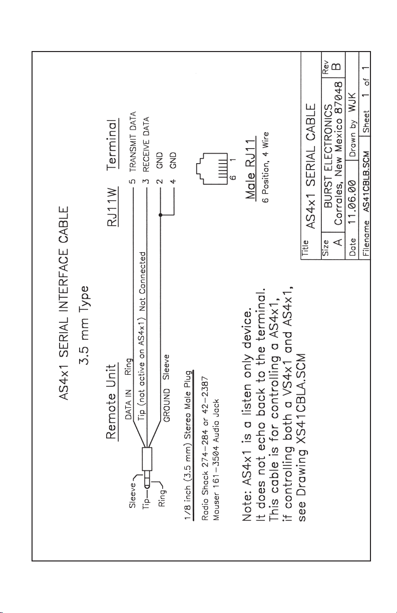
Connector: 3.5 mm 3 conductor (stereo connector)
3 AS4x1 Audio Switch
Page 6

Remote Control
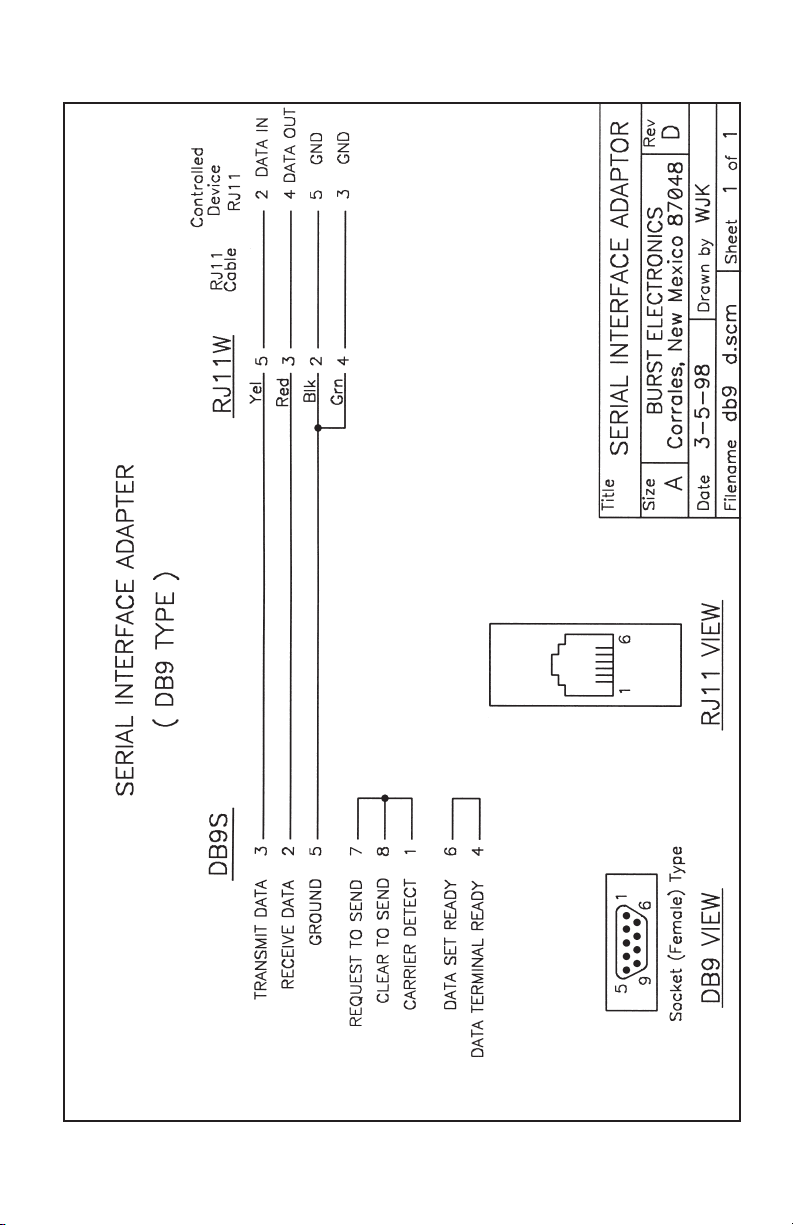
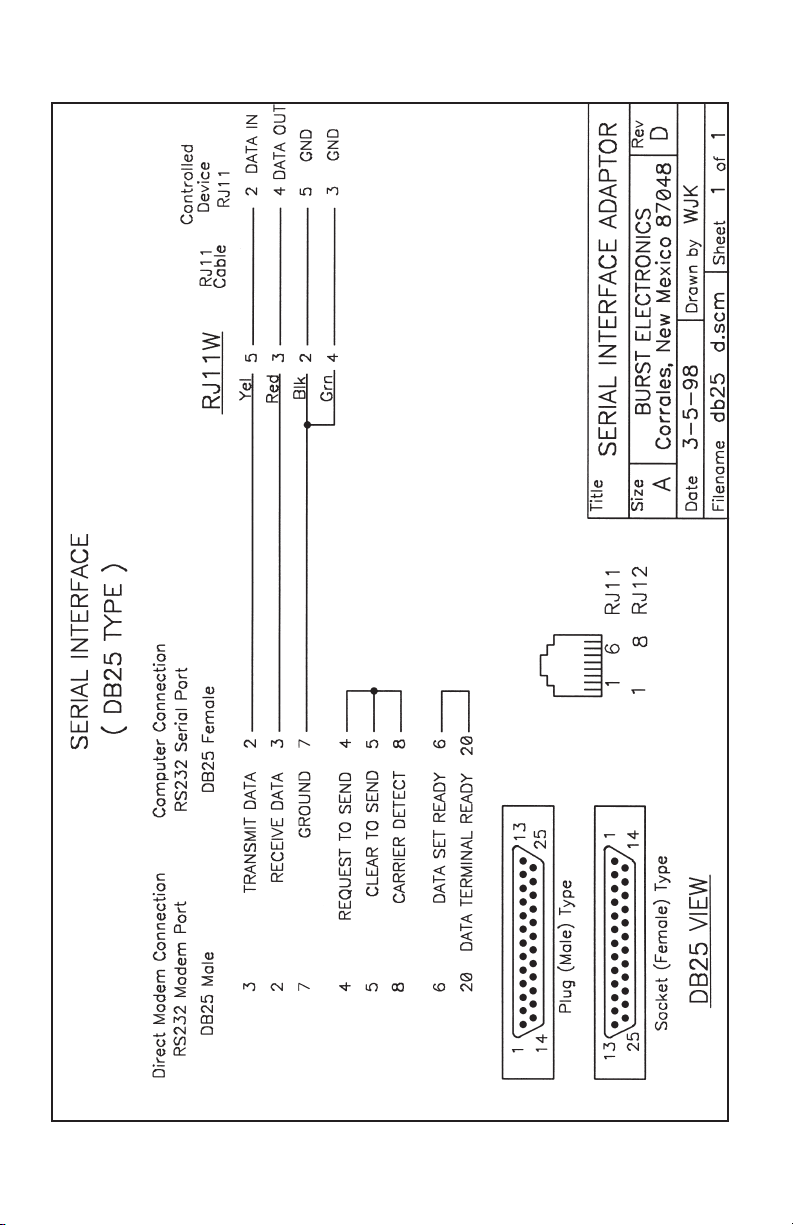
The RS232 Commands apply to the Model AS4x1R only.
The data transmission to the AS4x1R is 2400 baud 8N1.
To cause the AS4x1R to switch to an input, issue the
command: Ax, where x is the channel number. Example:
A2 will cause the AS4x1R to switch to channel two.
If a VS4x1R Video Switcher and a AS4x1R Audio Switcher
are used together, then the command Bx will cause both
units to switch.
Commands to the AS4x1R:
Command Function
Ax Switches to x Channel
Bx Switches to x Channel
and causes the VS4x1 to also switch
4 AS4x1 Audio Switch
Page 7

Audio/Video Switching
To switch both audio and video, use a AS4x1R FourChannel Audio Switcher and a VS4x1R Four-Channel
Video Switcher. These two units can be linked together via
RS232. With the two units linked, audio follows video and
audio breakaway is possible.
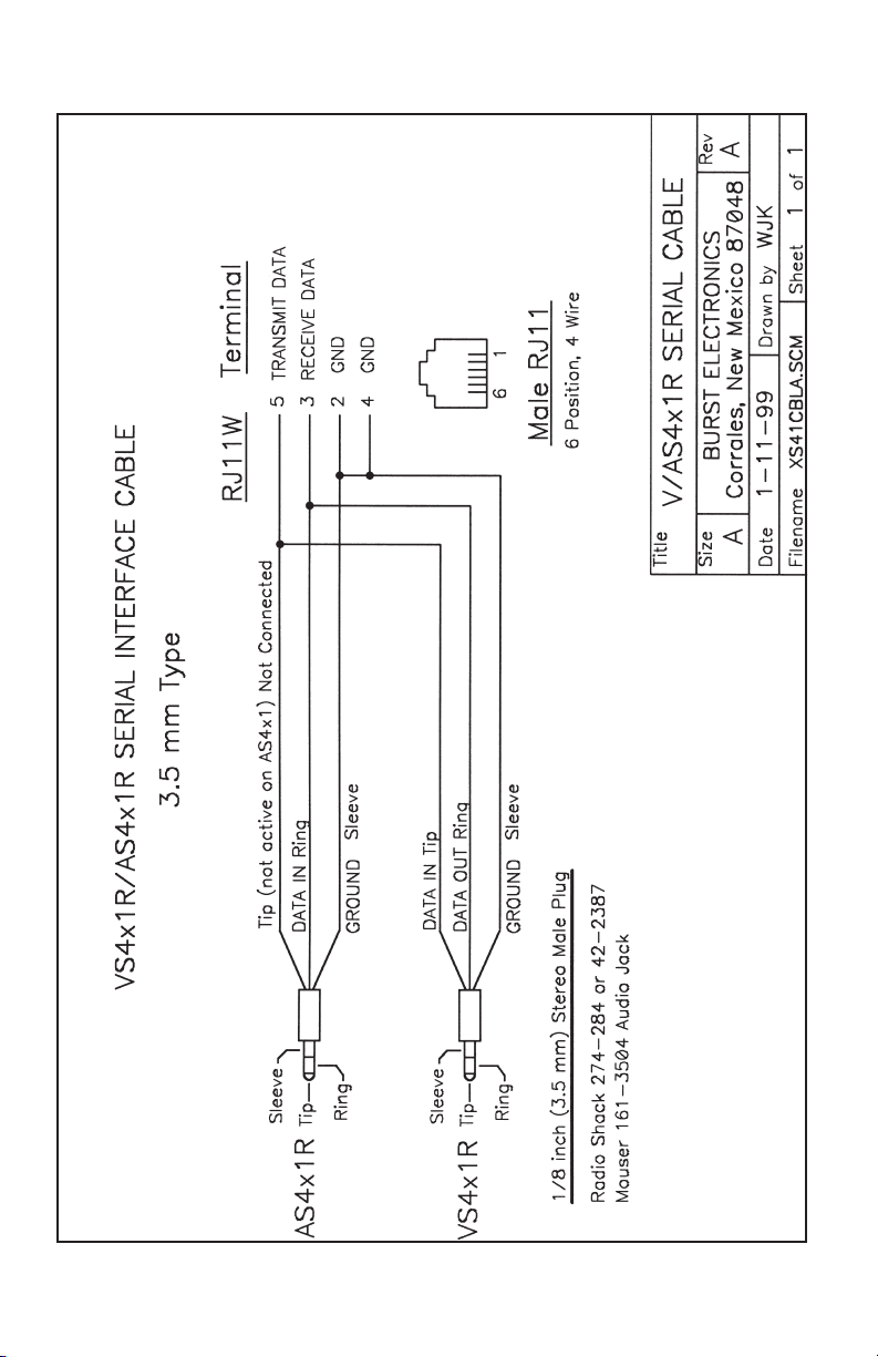
Interconnect the RS232 ports of the AS4x1R and VS4x1R
using a “Stereo Patch Cable” with 3.5 mm stereo plugs on
each end. An example is a Radio Shack 42-2387. See the
VS4x1 manual for more details.
5 AS4x1 Audio Switch
Page 8
Page 9
Page 10
Page 11
Page 12

 Loading...