

Page 1
Xtreme Tactical Riflescopes
User Guide
This user guide includes information for the
entire XTR II riflescope line. Please review
thoroughly, and pay close attention to the details
pertaining to your specific riflescope model.
Page 2

Congratulations on choosing the XTR II™riflescope from
®
Burris
. The XTR II has improved upon the original
Xtreme Tactical Riflescope design, now offering these
premium features:
• Five Times Zoom System. Highly versatile five times
zoom system allows for a larger field of view at close
ranges and better target acquisition at long ranges.
• Zero Stop Adjustment Knobs. Allows shooter to
quickly and easily revert back to the original sight-in
setting without counting clicks.
• Tactical Reticles.The XTR II line-up gives you a choice
in tactical appropriate reticles, including the XTR II
Ballistic 5.56 Rear Focal and Dual Focal Plane reticles;
the Ballistic CQ Mil reticle; the G2 Mil-Dot reticle; and
the F-Class MOA reticle. All provide accurate trajectory
and windage compensation and are ideal for tactical
applications. Some include illumination capabilities
compatible with night vision gear.
• Advanced Windage & Elevation Adjustment.
Accurate and repeatable reticle adjustments match
the measurement system of the reticle, making
windage and elevation adjustments fast and easy.
• Side Focus. Ergonomic side focus allows for easy-to-
reach parallax adjustment.
• High Performance Glass. Provides excellent brightness
and clarity with lasting durability – exactly what you
expect from Burris.
•Index-Matched, Hi-Lume® Multi-Coated Lenses.
Enhanced low-light performance and glare elimination,
making more shots possible and increasing your
success rate.
• Rugged, Combat-Ready Performance.Throw every-
thing you’ve got at these riflescopes – they can take it
and still deliver.
1
Page 3

How to use the XTR II Riflescope
Eyepiece Focusing
The eyepiece can be focused so that the reticle appears
sharp and black. Adjusting the focus is quick and easy
to do, just follow this procedure:
1. Point the scope at the sky or a plain wall and take a
quick glance through the scope. If the reticle appears
sharp and black, no further adjustment is necessary.
2. If the reticle does not appear sharp and black, take
quick glances through the scope while rotating the
focus ring until the reticle pattern is sharp and black.
NOTE: Do not look through the eyepiece as you turn
the focus ring. Your eyes will adjust to the out-of-focus
condition.
Parallax/Focus Adjustment
– Parallax adjustment is not available on 1x-5x
and 1.5x8x models –
Parallax is the apparent movement of the reticle in
relation to the target when the eye is not directly in
line behind the center of the scope. Images from
different distances focus in front of or behind the
scope’s reticle. Parallax is more noticeable with higher
magnification scopes.
To use the parallax/focus adjustment, rotate the knob
on the left side of the adjustment turret until the
numeral corresponding to the known target distance
lines up with the reference mark. If the distance is
unknown, rotate the adjustment knob until the target
image is sharply focused.
When the scope is set parallax-free for the distance
you are viewing, you should be able to move your eye
side-to-side or up and down without seeing the reticle
move appreciably in relation to the target.
2
Page 4

Windage/Elevation Adjustment for Multi-Turn Knobs
– Applies to 2x-10; 3x-15x; 4x-10x; 5x-25x; and 8x-40x models –
The windage and elevation knobs are designed for
precise adjustment. The click value for each knob is
indicated on the dial.
For shooting at extreme distances, the elevation knob
offers up to 8 mils/rotation with multi revolutions of
adjustment (8x-40x models have 10 MOA/rotation).
This riflescope is shipped from the factory with the
optical center set 20 MOA below center. Without
tapered bases, the initial sight-in or bore sighting will
likely produce a considerably high initial point of
impact. Because of the Zero Stop feature, as shipped
from the factory the scope has no immediate capability
for downward point-of-impact adjustment.
Use the following procedure whenever you need
downward point of impact adjustment:
1) Turn the elevation adjustment knob clockwise to “0”.
2) Use the 2mm hex wrench
supplied with the scope to
loosen the set screws on
the elevation adjustment
knob located just under
the top of the knob.
3) Pull up slightly on the
adjustment knob to the
second white hash mark on
the turret. Turn the knob
clockwise slightly more
(maybe 2-5 mils more) than
the number of mils needed
to achieve zero.
4) Retighten the set screws. Adjust the elevation down
the required amount.
5) Once the elevation adjustment is complete, once
again loosen the two set screws and reset the knob
3
Page 5
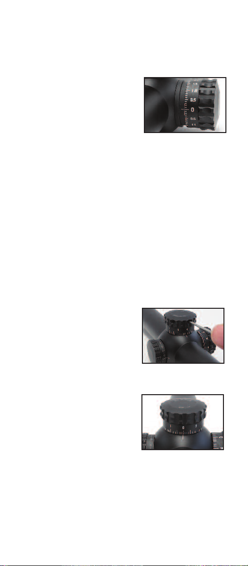
“0”. With the screws loose, push down firmly on the
knob until it is fully seated on the turret base and then
retighten the set screws.
NOTE: Windage adjustments
are made with a multi-direction
adjustment knob. Zero is set
with an indexing mark to allow
for left and right adjustments.
Failure to zero at the index
mark may result in limited
windage adjustment.
Windage/Elevation Adjustment for Single-Turn Knobs
– Applies to 1x-5x and 1.5x-8x models –
The windage and elevation knobs are designed for
precise adjustment. The click value for each knob is
indicated on the dial.
The elevation knob at the top of the tube provides 9.3
mRAD of adjustment in one full turn and features a
Zero Stop. The windage knob, located on the right side
of the tube, provides up to 4.6 mRAD of adjustment in
both directions.
Both knobs can be reset to “0”
once the scope is sighted-in. To
reset the knobs to “0,” use the
hex wrench supplied with the
scope to loosen the set screws
located at the top of the
adjustment knobs.
Proper Windage Zero
The dial should spin freely.
Rotate the knob until the “0”
lines up with the hash mark
indicator, and then retighten
the set screws. The knob is not
intended to come up or off, but
if the set screws are loosened too far, the knob can be
removed. The scope is still fully sealed if this does
accidentally occur.
4
Page 6

Illuminated Reticle Adjustment
Models with an illuminated reticle make it easier to see
the reticle in low light conditions.The intensity of the
illumination is controlled by the rotary illumination
switch located on the left side of the adjustment turret.
The switch has 11 intensity levels and a “battery saver”
position in between each level that turns off the
illumination. The illumination levels rise in brightness
intensity from 1–11, with the lowest levels capable of
working with night vision equipment, the middle levels
ideal for low light conditions, and the highest levels
suitable for daytime usage. The “Off” positions at the
minimum and maximum ranges turn the circuit off
completely and should be used when the scope is not
in use. Each level also has a detent to prevent unintended
changes during use.
Time-Out Function: XTR II Riflescopes arrive from the
factory with an automatic Time-Out Function. After XX
hours the illumination will automatically shut off to
conserve battery life. This function can be disabled by
Burris upon request or you can deactivate the setting
yourself. To learn how, visit www.burrisoptics.com/XTRII
or contact our customer service department.
The reticle is powered by a 3-volt lithium cell battery
#CR2032. To install a new battery, simply unscrew the
battery cap on the rotary switch and install the new
battery flat side (+) up. It is advisable to remove the
battery for long-term storage (over a month).
5
Page 7

Mounting the Scope
Most XTR II riflescopes require 34mm rings; the 1x-5x
requires 30mm rings. We recommend using high-quality
rings and bases, like the Burris Xtreme Tactical Rings
and Xtreme Tactical Bases. Quality components ensure
that your scope will remain safely and securely
mounted, and will provide the maximum accuracy. Use
care when mounting your scope as damage caused by
improper mounting is not covered by the Burris Forever
Warranty.
Care & Maintenance
The XTR II riflescope is fully waterproof and fogproof.
To protect the objective and ocular lenses, it comes
equipped with flip-up scope caps. In the event that
the lenses are subjected to dust, dirt, or mud, follow
these steps to clean and protect the lens surface. Failure to remove grit before final cleaning is sure to
damage lens coatings.
Coarse dirt/debris must be removed from the lens
surface. The most convenient way to clean a lens surface is to use a Lens Pen. Position the scope so particles will fall away from the lens, and then use the Lens
Pen or soft brush to gently whisk away the debris while
blowing on the lens to dislodge the particles. For
heavy dirt, like dried mud, use a spray of clean water or
lens cleaning fluid to remove the dirt.
Your Burris riflescope will provide reliable performance
given reasonable care and treatment. All moving
assemblies are permanently lubricated. Only occasional
cleaning of the outside of the scope and the exterior
lenses is required. Never disassemble your scope.
Disassembly by anyone other than our factory will
void the warranty. If you have any other problems with
your riflescope, return it to the Burris factory for repair.
6
Page 8

XTR II Riflescope Reticles
XTR II riflescopes give you a variety of reticle choices, and
feature front, rear, or dual focal plane systems.
Front Focal Plane (FFP)
Front Focal Plane systems (sometimes referred to as
First Focal Plane systems) place the reticle in front of the
erector assembly or zoom mechanism. This allows the
reticle to change size as magnification is adjusted. In
FFP systems, when magnification is increased, the
reticle size grows; as magnification is lowered, the
reticle size shrinks. Because the reticle is changing with
magnification, the measurements of the reticle are
always correct and are proportional to whatever power
setting you may be on. This can be very useful in tactical
situations when reticles are used to determine size and
distance of a target, and when using the reticle for trajectory compensation at multiple magnification settings.
Low Power View
High Power View
Rear Focal Plane (RFP)
Rear Focal Plane systems (sometimes referred to as
Second Focal Plane systems) place the reticle to the rear
of the erector assembly or zoom mechanism. This is the
most common reticle system and is found in most
hunting optics. Because the reticle is behind the zoom
mechanism, the size of the reticle is constant and does
not change when magnification is adjusted. This will
make the reticle appear to consume more of the target
on low power; on high power, the reticle will appear to
consume less of the target, which is beneficial for longrange, precision shooting.
Low Power View
High Power View
Since the reticle size never changes on RFP systems, it is
important to understand that the reticle measurements
will only be correct on one specific power. For the XTR II
1x-5x riflescope, the measurements are correct at 5x power.
7
Page 9

Dual Focal Plane System
The XTR II Dual Focal Plane system separates the center
aiming point and crosshairs of the reticle, placing the
center in the RFP and the crosshairs in the FFP. This
allows the center aiming point to remain a constant
size, ensuring the dot is large enough to be effective at
low power for close quarter shooting. The crosshairs
(which are in the FFP) change size with magnification,
meaning the measurements are always correct and
proportionate to the magnification. Since the two
pieces of the reticle are acting independently, the
pieces will overlap slightly at certain magnifications, but
this will not prevent the shooter from using the reticle
correctly.
Low Power View
High Power View
The center aiming point, or the RFP portion of the reticle,
has illumination capabilities. The crosshairs, or the FFP
portion of the reticle, have no illumination capability.
8
Page 10

XTR II Ballistic 5.56 Gen 2 Illuminated Reticle (RFP)
.25 mil
Outside dia. = 2.25 mil
Inside dia. = 1.75 mil
.5 mil
.125 mil
1 mil
.5 mil
1 mil
Each tick mark
subtends 18” at
distance at 5x.
.
5 mil
.
5 mil
1
mil
1
mil
Entire line width of
trajectory ladder and
width of tick marks
along trajectory ladder
subtend 3” (75mm) at
each distance.
100
yards
200
300
300
200
100
yards
4
5
6
7
8
9
10
MOA
Corr. @ 100 yards
-1.1
-3.3
-6.1
-9.5
-13.6
-18.4
-24.3
-31.3
-39.6
-.32
-96
-1.77
-2.76
-3.96
-5.35
-7.07
-9.10
-11.52
-1.2
-3.5
-6.4
-10.0
-14.2
-19.3
-25.4
-32.7
-41.4
00
Mils
0
Rear Focal Plane Reticle
Calibrated to a .223 62gr FMJ at 3025 fps@2000’ altitude, .307 BC.
*Subtensions shown for High Power Magnification.
XTR Ballistic 5.56 Gen 2 Illuminated Rear Focal Plane
reticle helps shooters achieve maximum accuracy with
5.56/.223 ammunition. It utilizes milradian measurements
and an illuminated “broken circle” with center dot that
allows for ultra-fast engagement at short distances.
The RFP design keeps the reticle size constant,ensuring
it’s large enough to be successful when close quarter
shooting while still performing well during long-range,
precision shooting.
9
Page 11

XTR II Ballistic 5.56 Gen 2 Illuminated Reticle (DFP)
0.2 mil
O
utside dia. = 2.2 mil
I
nside dia. = 1.8 mil
.
5 mil
.125 mil
.5 mil
Each tick mark
length subtends
18” at distance.
Entire line width of
trajectory ladder and
width of tick marks
along trajectory ladder
subtend 3” (75mm) at
each distance.
1 mil
.2 mil
.
5 mil
.
5 mil
1
mil
1
mil
MOA
Corr. @ 100 yar
100
yards
200
300
300
200
100
yards
-1.1
-3.3
-6.1
-9.5
-13.6
-18.4
-24.3
-31.3
-39.6
-.32
-96
-1.77
-2.76
-3.96
-5.35
-7.07
-9.10
-11.52
-1.2
-3.5
-6.4
-10.0
-14.2
-19.3
-25.4
-32.7
-41.4
00
Mils
0
4
5
6
7
8
9
10
Dual Focal Plane Reticle
Calibrated to a .223 62gr FMJ at 3025 fps@2000’ altitude, .307 BC.
XTR Ballistic 5.56 Gen 2 Illuminated Dual Focal Plane
reticle helps shooter achieve maximum accuracy with
5.56/.223 ammunition. It utilizes milradian measurements
and an illuminated “broken circle” with center dot that
allows for ultra-fast engagement at short distances.
The DFP design allows the illuminated “broken circle”
to remain a constant size, while the crosshairs change
size with magnification ensuring accurate measurements
at any power.
High Power View
Low Power View
10
Page 12

XTR II Ballistic CQ Mil Illuminated Reticle
Outside dia. = 2.25 mil
Inside dia. = 1.75 mil
.5 mil
.5 mil
.25 mil
1 m i l
1 . 5 m i l
.5 mil
1 m i l
1 m i l
2 m i l
2
5
10
1
mil1 mil
1
mil1 mil
1 mil
Rear Focal Plane Reticle
XTR Ballistic CQ Mil Illuminated Rear Focal Plane reticle
utilizes milradian measurements and an illuminated
“broken circle” with center dot that allows for ultra-fast
engagement at short distances. The RFP design keeps
the reticle size constant, ensuring it’s large enough to
be successful when close quarter shooting while still
performing well during long-range, precision shooting.
11
Page 13

G2 Mil Dot Illuminated Reticle
Front Focal Plane Reticle
The G2B Illuminated Mil-Dot Focal Plane Reticle is a
mil-based reticle with hash marks in between the mil
dots for more precise aiming, distance measurement,
holdover and hold-off for wind. The center portion of
the reticle is illuminated on models with illumination
capabilities. FFP design means the reticle size changes
with magnification, ensuring that the reticle measurements are always correct and proportional to whatever
power setting you may be on. This reticle is excellent in
tactical situations when determining size and distance
of a target is critical.
Reticle Subtensions:
Units AB C D E F GH J K L
mRad 10 0.5 0.5 0.2 0.05 .5 1 0.05 0.05 52
in/100 yd. 36 1.8 1.8 0.72 .18 1.8 3.6 .18 .18 18 7.2
cm/100 m 100 5.0 5.0 2 0.5 5 10 0.5 0.5 50 20
12
Page 14

F-Class MOA Illuminated Reticle
.
125 MOA
Center dots are illuminated
B
ox is 15 MOA
2
MOA
1 MOA
.
5 MOA
1
MOA
.
5 MOA
20 15 10 5 5 10 15 20
5 10 15 20
20 15 10 5
5
15
10
25
30
35
Line Thickness= 1/20 MOA
Line Thickness= 1/60 MOA
Front Focal Plane Reticle
The F-Class MOA Illuminated Reticle is optimized for
long-range F-Class competitive shooting. The reticle is
laid out in .5 MOA increments, and include a secondary
horizontal crosshair designed to give the shooter 20
MOA additional adjustment beyond the capability of
the turret adjustments while still retaining the ability
to use the MOA hash marks for wind hold-off. An
illuminated center dot is found at the 0, 10, 20, and 30
MOA marks.
NOTE: It is only possible to use the 20 MOA grid in
lower magnifications when the field of view is large
enough to see it; it will disappear from view in higher
magnification.
Close-Up of Center Crosshairs at
0 MOA and 20 MOA
13
Page 15

Warranty
This XTR II line of riflescopes is covered by the
Burris Forever Warranty!
Thank you for choosing Burris. You can be confident
that the optic you purchased is built to the most
exacting standards. You can count on Burris to perform
every time you use it.
We’re so confident in the craftsmanship of our products
that we back them with a no questions asked Forever
Warranty.
We will repair or replace your Burris optic if damaged
or defective:
• No charge to you.
• No questions asked.
• No matter whose fault it is.
• No warranty card needed.
• No receipt required.
• Automatically transferred to future owners.
We walk in our customers’ shoes. We see what you see.
We don’t just design and build superior optics, we live
our lives as passionate hunters and shooters. We insist
that our equipment provide the ultimate in confidence
– for us and for you.
The American ingenuity, innovation and technology in
our products provide you the confidence to hit any
target, at any range, again and again.
The Burris Forever Warranty is your extra assurance for
the best possible shooting experiences, because every
Burris tells a story – yours and ours.
14
Page 16

Burris Company
331 East 8th St.
Greeley, CO 80631
(970) 356-1670
BurrisOptics.com
Facebook.com/BurrisOptics
INSTR-9000
 Loading...