

Page 1

Burris Co.
311 East 8th Street
Greeley, CO 80631
970-356-1670
www.burrisoptics.com
Page 2
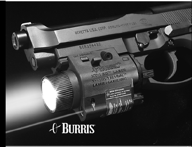
XT®-120
Xtreme Tactical
Laser Flashlight
Page 3

CAUTIONS AND WARNINGS
1. Prior to the operation of any firearm in conjunction with the XT-120 make
sure that you completely understand all safety precautions and procedures
contained in the XT-120 operator’s manual as well as in the manual for your
firearm. Failure to follow these precautions may result in damage to property,
serious injury or death.
2. Always follow proper safety precautions with any firearm whether or not
equipped with the XT-120.
3. Never point a firearm at anything you do not intend to shoot whether or
not equipped with the XT-120.
4. When the XT-120 is attached to a firearm, pointing the XT-120 at a person
or object will automatically also point the firearm at that person or object.
Therefore, never point the XT-120 at anything you do not intend to shoot. The
XT-120 produces adequate light levels to illuminate a subject without the
1
Page 4

need to point directly at the subject. Light from the XT-120 can be safely
pointed at a wall, ceiling or floor and the resulting reflected light will be
sufficient to identify the object of interest. The XT-120’s light beam can also
be adjusted for wide-angle illumination.
5. The XT-120 allows you to operate the ON/OFF switch while your finger is
outside the trigger guard. Do not insert your finger inside the trigger guard
until prepared to fire the weapon.
6. Before attaching or detaching the XT-120, always make certain the the
chamber of your firearm is empty by following the “clearing” procedure
detailed in your firearm’s operator’s manual.
7. Before cleaning the XT-120, replacing bulbs or batteries or any other
maintenance, remove the XT-120 from the firearm.
2
Page 5

8. Do not operate the XT-120 around any flammable or combustible material
such as cleaning solvents, paints or gasoline. Do not operate the XT-120
in an environment which may contain flammable gasses such as evaporated gasoline.
9. Test the XT-120 periodically, especially after periods of non-use or prior
to employment to verify that it is operating properly.
10. The XT-120 requires completely charged batteries for proper operation.
Be careful when handling batteries to prevent leakage of harmful chemicals
which can damage skin, clothing or the XT-120 itself. To avoid injury, do
not expose batteries to excessive heat or allow any material leaked from a
battery to come in contact with eyes or skin. Follow instructions from the
battery manufacturer regarding the proper handling, storage and disposal
of batteries.
11. CAUTION: The bulb in the XT-120 generates intense heat. When
switched ON, never place the light on its face (bulb down) or you may
cause damage to the XT-120 or the surface on which it is placed.
3
Page 6

DANGER
Avoid Direct Exposure to Laser Radiation Beam
Visible Laser
Output Power: <5mW
Wavelength: 640±40nm
Class IIIa Laser Product
• Do not look into the laser beam directly or through binoculars or telescopes.
• Do not point the laser beam at mirror-like or reflective surfaces.
• Do not shine the beam into the eyes of anyone.
4
Page 7
DANGER
LASER RADIATION-AVOID
DIRECT EYE EXPOSURE
Max. Output-5mW, Wavelength:630
Complies with 21 CFR Chapter 1,
Model: XT-120
Manufacture: Feb. 2005
Laser radiation is emitted
AVOID EXPOSURE
from the APERTURE
331 East 8th Street, Greeley Colorado
from the APERTURE
AVOID EXPOSURE
Laser radiation is emitted
5
OFF VIS ILL
XT-120 Warning/Aperture/Mode Label
Burris Company
VIS
ILL
Page 8
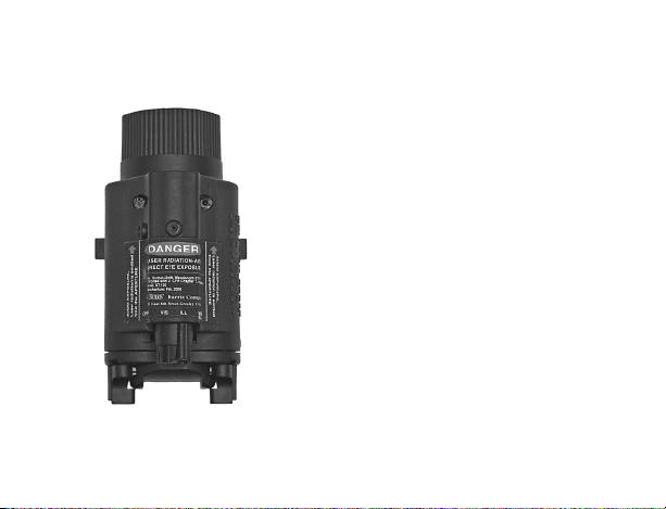
For the location of the Laser
Warning Label on the unit see
the photo at left.
WARNING
Do not store the XT-120 with
batteries installed.
CAUTION
Do not over turn the adjusters.
6
Page 9

7
Page 10

Mounting the XT-120
1. With your “cleared and safe” firearm in either hand, hold the
XT-120 in the other hand with the bulb pointing away from your
body in the same direction as the weapon muzzle.
2. Raise the XT-120 up and toward the firearm with the grooves of
the XT-120 aligned with the firearm grooves. Slide the XT-120 back
until the latch engages with an audible “click.”
3. Test the security of the latch by attempting to slide the XT-120
forward. It should remain secure and, if so, is safely mounted.
8
Page 11

Step 2
9
Step 1
Page 12

Dismounting the XT-120
1. Place your hand under the XT-120 with your
index finger and thumb on each side of the
latch bars. Squeeze the bars with the finger
and thumb to disengage the latch bar from the
firearm.
2. With the latch bars pressed in, slide the XT-120 forward, down
and away from the weapon muzzle until clear of the grooves.
CAUTION
Never put your hand in front of the muzzle of the firearm. Be sure to
push the XT-120 forward, down and away from the muzzle.
Latch Bar
10
Page 13

Operating the Switch
The rocker switchhas twopositions: MOMENTARY
and STEADY ON. The rocker switch is part of
the backplate and you should not attempt to
disassemble.
MOMENTARY POSITION
Rotate the rocker switch in a clockwise direction
to turn the light on in a MOMENTARY position.
Release the rocker switch to turn the light off.
STEADY-ON POSITION
Rotate the rocker switch in a counter-clockwise direction until it
clicks in the STEADY-ON position to turn the light on and keep it on.
Push the switch clockwise to release it from the STEADY-ON position
and turn the light off.
Rocker Switch
11
Mode
Page 14

Mode Switch:
A rotary Mode Selection Switch on the XT-120 provides the option
of four positions each indicated on the warning label - “OFF”,
“VIS”, “ILL” and “VIS/ILL.”
After activating the rocker switch, the modes are:
OFF - the system will not operate
VIS - only the visible laser is operable.
ILL - only the white flashlight is operable.
VIS/ILL - both the visible laser and white
flashlight operate.
CAUTION: The bulb in the XT-120 generates intense heat. When
switched ON, never place the light on its face (bulb down) or you
may cause damage to the XT-120 or the surface on which it is
placed.
12
Page 15

ZEROING PROCEDURES
Prior to using any firearm with the XT-120, be sure to read and understand
all procedures and safety precautions associated with your weapon
and the XT-120.
Follow the proper “clearing” procedures for your firearm before
attempting to mount or dismount the XT-120.
When you squeeze the trigger of your firearm you should expect the
weapon to fire so be absolutely certain of your target and background before firing.
Zeroing the XT-120 on a 25 meter range with target.
1. Set up a target at 25 meters.
2. Following the proper procedures, mount the XT-120.
3. Using the mode switch knob, select the “VIS” mode.
13
Page 16

4. Rotate the rocker switch to one side
until it clicks “ON.”
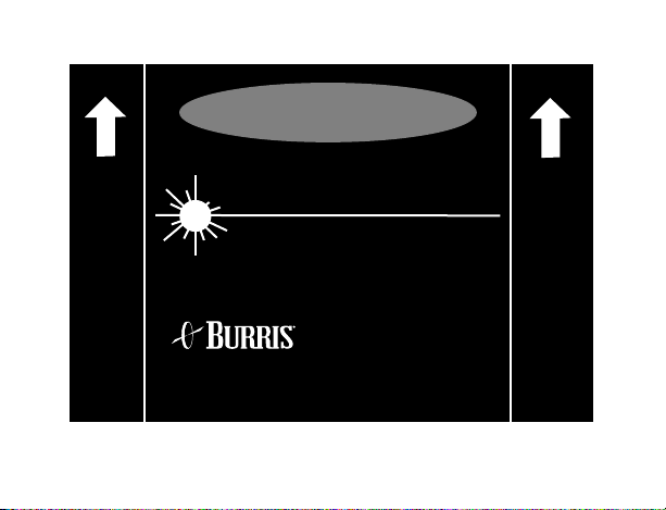
5. While aiming through the weapon’s
iron sights, adjust the visible aim point
of the XT-120 with the provided
adjusting (hex) tool until the aiming
point of the beam is superimposed
over the firearms’s iron sight aiming
point (see diagram).
6. Fire three rounds into the center of the
target aiming point at 25 meters.
7. Compare the impact point of the shot
group with the beam’s aiming point.
8. Make additional adjustments as
necessary until the beam coincides
with your point of impact.
9. Turn the XT-120 OFF.
Laser Spot
Rear Iron Sight
Front Iron Sight
14
Page 17

FOCUSING
Turn the bezel on the XT-120
until you have your desired
focus being careful not to
unscrew the bezel completely.
CAUTION
DO NOT place your hand in
front of the firearm muzzle
while turning the bezel.
15
Page 18

BULB REPLACEMENT
With the XT-120 detached
from the firearm, turn the bezel
counterclockwise until it
comes free from the retaining
threads. Remove the old bulb
as shown and insert a new
bulb in its place. Replace the
bezel by carefully pushing
down and rotating the bezel
clockwise making sure that
threads are engaged properly
to prevent stripping the threads.
16
Page 19

BATTERY
REPLACEMENT
1. With the XT-120 detached
from the firearm, hold the unit
in one hand and, with the
thumb of your other hand,
press down on the tab in the
top center of the backplate.
2. While keeping the tab depressed,
pivot the backplate away from the body
of the XT-120.
3. Remove the batteries by tipping the bezel upward to
allow the two 3-volt Lithium CR123A batteries to slide
out of their receptacle.
17
Tab
Retaining
Slot
Page 20

4. Note the raised markings indicating battery orientation. Hold the
XT-120 with mounting rails on top and the battery receptacle facing
you. Insert a battery on the left side with the negative end first. Insert
the other battery on the right side with the positive end first.
5. Place the bottom lip of the backplate into the bottom groove of the
battery compartment and pivot upward until the tab engages into
the retaining slot with an audible “click.”
6. Ensure proper functioning by manipulating the mode selection
switch and rocker switch to make sure that the light turns “ON.” If
not, make sure that the backplate is installed properly and if the light
still does not operate, remove the backplate and make sure that the
batteries are installed correctly.
CAUTION:
We recommend that you DO NOT store the XT-120 while batteries
are installed.
18
Page 21

MAINTENANCE
WARNING:
Make sure the weapon has been “cleared” and on SAFE before mounting or
dismounting the XT-120 by following the instruction manual for your firearm.
Allow bulb assembly to completely cool before servicing.
1. Clean the XT-120 with mild, soapy water and rinse thoroughly with clean
water to eliminate residue. Dry with a soft cloth. Clean anytime after the
XT-120 becomes dirty or after exposure to salt water.
2. Clean the aiming and illumination beam windows by wiping with a soft cloth
moistened with clean water, alcohol or window cleaner. To facilitate clean-up
of the flashlight lens, rub a small amount of oil or lubricating solvent on the
exterior lens ONLY prior to shooting.
3. Clean the electrical contacts with cotton swabs dipped in alcohol. For
heavier build-up, use a pencil eraser.
4. For replacement bulbs (Part #626080), contact your dealer or contact Burris
for the location of your nearest distributor.
19
Page 22

LIMITED WARRANTY
BURRIS 12 MONTH LIMITED WARRANTY
Burris warrants for 12 months after purchase that its products will be free
from defects in material and workmanship. At its sole discretion, Burris will
either repair or replace, at no charge, any product or part (with the exception
of the lamp and battery) which is found to be defective under normal use and
service. Burris’s obligation to either repair or replace shall be the purchaser’s
sole and exclusive remedy under this warranty. The warranty does not cover
battery leakage.
This warranty extends only to the original owner. There are no warranties,
expressed or implied, other than as set forth on this page and Burris disclaims
any warranties of merchantability or fitness for a particular purpose. Burris
shall not be liable for incidental. consequential, or special damages arising
out of or in connection with product use or performance. For service, repair,
or replacement, return unit “UPS Prepaid” with a copy of the sales receipt to
Burris.
20
Page 23

SERVICE:
The XT-120 EXTREME TACTICAL LASER FLASHLIGHT
For service and repair, send via “UPS Prepaid” with a copy of the
sales receipt to:
Burris Co.
311 East 8th Street
Greeley, CO 80631
Attn: Customer Service
Phone: 970-356-1670
Fax: 970-356-8702
www.burrisoptics.com
The exportation of this product falls under the jurisdiction of the U.S.
Commerce Department Bureau of Industry and Security and is subject to
the Export Administration Regulations.
21
Page 24

22
 Loading...