

Burr Brown Corporation DCP012415DP Datasheet
®
Miniature 24V Input, 1W Isolated
UNREGULATED DC/DC CONVERTERS
©
1997 Burr-Brown Corporation PDS-1383C Printed in U.S.A. February, 1999
FEATURES
● STANDARD JEDEC PLASTIC PACKAGE
● LOW PROFILE: 0.15" (3.8mm)
● SYNCHRONIZABLE
● OUTPUT SHORT CIRCUIT PROTECTION
● THERMAL SHUTDOWN
● STARTS INTO ANY CAPACITIVE LOAD
● EFFICIENCY: 76% (±15V Out)
● 1000Vrms ISOLATION
● 400kHz SWITCHING
● 93 MILLION HOURS MTTF
● AVAILABLE IN TAPE AND REEL
DESCRIPTION
The DCP0124 family is a series of high efficiency,
24V input isolated DC/DC converters. In addition to
1W nominal galvanically isolated output power capability, the range of DC/DCs are also fully
synchronizable. The devices feature thermal shutdown,
and overload protection is implemented via watchdog
circuitry. Advanced power-on reset techniques give
superior reset performance and the devices will start
into any capacitive load up to full power output.
The DCP01 family is implemented in standard-molded
IC packaging, giving outlines suitable for high volume
assembly.
DCP0124
Series
I
BIAS
Power
Stage
V
OUT
÷ 2
Reset
800kHz
Oscillator
Watch-dog/
start-up
PSU
Thermal
Shutdown
SYNC
OUT
SYNC
IN
V
S
0V
Power Controller IC
0V
APPLICATIONS
● POINT OF USE POWER CONVERSION
● GROUND LOOP ELIMINATION
● DATA ACQUISITION
● INDUSTRIAL CONTROL AND
INSTRUMENTATION
● TEST EQUIPMENT
DCP0124
DCP0124
International Airport Industrial Park • Mailing Address: PO Box 11400, Tucson, AZ 85734 • Street Address: 6730 S. Tucson Blvd., Tucson, AZ 85706 • Tel: (520) 746-1111
Twx: 910-952-1111 • Internet: http://www.burr-brown.com/ • Cable: BBRCORP • Telex: 066-6491 • FAX: (520) 889-1510 • Immediate Product Info: (800) 548-6132

2
DCP0124
®
SPECIFICATIONS
At TA = +25°C, VS = +24V, unless otherwise specified.
DCP0124 SERIES
PARAMETER CONDITIONS MIN TYP MAX UNITS
OUTPUT
Power V
S
+ 4% 1 W
100% Full Load 0.92 W
Voltage (V
NOM
)
(1)
DCP012405 75% Full Load 4.75 5 5.25 V
DCP012415D (+V) 75% Full Load +14.25 +15 +15.75 V
DCP012415D (–V) 75% Full Load –12 –15 –15.75 V
Voltage vs Temperature ±0.08 %/°C
Short Circuit Duration V
S
± 10% Indefinite
Ripple C
L
= O/P Capacitor = 11µF 25 mVp-p
100% Full Load
INPUT
Nominal Voltage (V
S
) 24 V
Voltage Range –10 10 %
Supply Current 100% Full Load 59 mA
Reflected Ripple Current C
IN
= I/P Capacitor = 1µF 8 mArms
50% Full Load
ISOLATION
Voltage
(2)
1s Flash Test 1 kVrms
Continuous Voltage
(3)
1 kVrms
Insulation Resistance >1 GΩ
Input/Output Capacitance 2.5 pF
LOAD REGULATION
DCP012405 10% to 100% Load 17 23 %
10% to 75% Load 9 %
75% to 100% Load –4 %
DCP012415D 10% to 100% Load 22 35 %
10% to 25% Load 11 %
25% to 75% Load 8 %
75% to 100% Load –4 %
SWITCHING/SYNCHRONIZATION
Oscillator Frequency (f
OSC
) Switching Frequency = f
OSC
/2 800 kHz
Sync Input Low 0 0.8 V
Sync Input Current V
SYNC
= +2V 48 µA
Reset Time 3.8 µs
SYNC
OUT
Frequency 400 kHz
GENERAL
No Load Current
DCP012405 0% Full Load 14 mA
DCP012415D 0% Full Load 17 mA
Efficiency
DCP012405 100% Full Load 65 %
10% Full Load 34 %
DCP012415D 100% Full Load 76 %
10% Full Load 36 %
MTTF
(3)
TA = +85°C 136,000 hrs
T
A
= +55°C 2,630,000 hrs
T
A
= +25°C 92,600,000 hrs
Weight 14-Pin PDIP 1.08 g
THERMAL SHUTDOWN
Die Temperature 115 140 °C
Shutdown Current 3mA
TEMPERATURE RANGE
Operating –40 100 °C
NOTES: (1) 100 % load current = 1W/V
NOM
typical. (2) Rated working voltage = 130Vrms (IEC950 convention). (3) Life test data.
The information provided herein is believed to be reliable; however, BURR-BROWN assumes no responsibility for inaccuracies or omissions. BURR-BROWN assumes
no responsibility for the use of this information, and all use of such information shall be entirely at the user’s own risk. Prices and specifications are subject to change
without notice. No patent rights or licenses to any of the circuits described herein are implied or granted to any third party. BURR-BROWN does not authorize or warrant
any BURR-BROWN product for use in life support devices and/or systems.
3
®
DCP0124
DCP0124
1
2
5
6
7
14
8
V
S
0V
0V
+V
OUT
NC
SYNC
IN
SYNC
OUT
DCP0124
1
2
5
6
7
14
8
V
S
0V
0V
+V
OUT
–V
OUT
SYNC
IN
SYNC
OUT
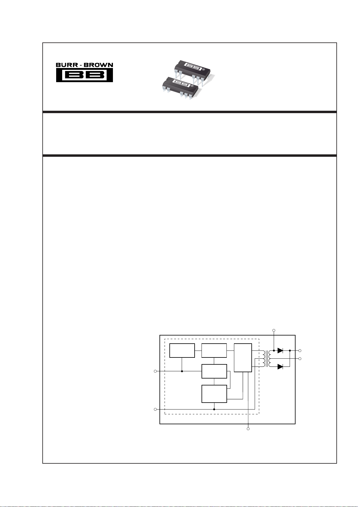
Top View DIP
PIN CONFIGURATION (Single)
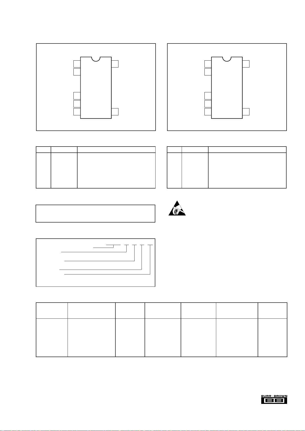
Top View DIP
PIN CONFIGURATION (Dual)
PIN DEFINITION (Single)
PIN # PIN NAME DESCRIPTION
1VSVoltage Input.
2 0V Input Side Common.
5 0V Output Side Common.
6+V
OUT
+Voltage Out.
7 NC No Connection.
8 SYNC
OUT
Unregulated 400kHz Output from Transformer.
14 SYNC
IN
Synchronization Pin.
PIN DEFINITION (Dual)
PIN # PIN NAME DESCRIPTION
1VSVoltage Input.
2 0V Input Side Common.
5 0V Output Side Common.
6+V
OUT
+Voltage Out.
7–V
OUT
–Voltage Out.
8 SYNC
OUT
Unregulated 400kHz Output from Transformer.
14 SYNC
IN
Synchronization Pin.
ELECTROSTATIC
DISCHARGE SENSITIVITY
This integrated circuit can be damaged by ESD. Burr-Brown
recommends that all integrated circuits be handled with
appropriate precautions. Failure to observe proper handling
and installation procedures can cause damage.
ESD damage can range from subtle performance degradation to complete device failure. Precision integrated circuits
may be more susceptible to damage because very small
parametric changes could cause the device not to meet its
published specifications.
Input Voltage........................................................................................ 29V
Storage Temperature...................................................... –60°C to +150°C
Lead Temperature (soldering, 10s) ................................................. 300°C
ABSOLUTE MAXIMUM RATINGS
DCP01
Basic Model Number: 1W Product
Voltage Input:
24V In
Voltage Output:
5V Out
Dual Output:
Package Code:
P = 14-Pin Plastic DIP
P-U = 14-Pin Plastic Dip Gull Wing
ORDERING INFORMATION
24 05
()
(D )
PACKAGE SPECIFIED
DRAWING TEMPERATURE PACKAGE ORDERING TRANSPORT
PRODUCT PACKAGE NUMBER
(1)
RANGE MARKING NUMBER
(2)
MEDIA
Single
DCP012405 14-Pin PDIP 010-1 –40°C to +100°C DCP012405P DCP012405P Rails
DCP012405 14-Pin PDIP Gull Wing 010-2 –40°C to +100°C DCP012405P-U DCP012405P-U Rails
" " " " " DCP012405P-U/700 Tape and Reel
Dual
DCP012415D 14-Pin PDIP 010-1 –40°C to +100°C DCP012415DP DCP012415DP Rails
DCP012415D 14-Pin PDIP Gull Wing 010-2 –40°C to +100°C DCP012415DP-U DCP012415DP-U Rails
" " " " " DCP012415DP-U/700 Tape and Reel
NOTES: (1) For detailed drawing and dimension table, please see end of data sheet, or Appendix C of Burr-Brown IC Data Book. (2) Models with a slash (/) are
available only in Tape and Reel in the quantities indicated (e.g., /700 indicates 700 devices per reel). Ordering 700 pieces of DCP012405P-U/700 will get a single
700-piece Tape and Reel. For detailed Tape and Reel mechanical information, refer to Appendix B of Burr-Brown IC Data Book.
PACKAGE/ORDERING INFORMATION
 Loading...