

Page 1
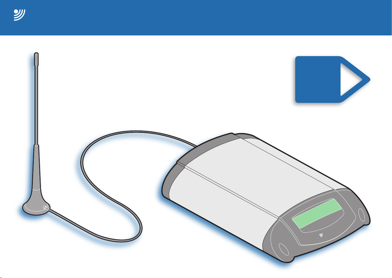
T9 series fixed cellular and landline terminals
BURNSIDE
www.burnsidetelecom.com
BURNSIDE
Burnside
Telecom
user guide
contents
•
introduction
•
installation
•
operation
•
menu map
•
Page 2

Contents Introduction Operation Further informationInstallation Index page 1
Contents
Introduction 2
Installation 3
Inserting your SIM card 4
Connecting a telephone 4
Connecting to a landline socket (‘L’ models only) 5
Connecting the magnetic mount antenna 5
Connecting the power adapter 6
Connecting to a computer (optional) 6
Connecting to external devices 7
Setting the internal clock 8
Operation 9
Making and receiving calls 9
Using the Phonebook 10
Text messaging 13
Using the call register 15
Tariff timer functions 16
Restrict call time 17
Call handling features 18
Outgoing call routing (‘L’ models only) 18
Manually selecting a landline connection 18
Manually routing a landline call via mobile connection (‘L’) 18
Landline dial through (‘L’ models only) 19
Forward landline (‘L’ models only) 20
Answering a landline call during a mobile call 22
Aborting fax or data calls 22
Incoming calls during menu access 22
Network call features 23
Further information 25
Contacting Burnside Telecom 25
Appendix 1: Menu options 26
Appendix 2: Data connection 32
Appendix 3: Using the input/output channels 34
Appendix 4: Remote commands 36
Appendix 5: Star hash codes 38
Appendix 6: Advanced configuration codes 39
Appendix 7: SMS key characters 42
Appendix 8: SIM security features 43
Important safety information 44
Index 45
Page 3
Contents Introduction Operation Further informationInstallation Index page 2
BURNSIDE
Burnside
Telecom
OR
BURNSIDE
Burnside
Telecom
BURNSIDE
Burnside
Telecom
Introduction
The Burnside T9 series fixed cellular terminal units provide
professional telephony features within a compact and easy-to-use
package.
All models in the range can be used with a standard desk phone (or
cordless phone) in locations where wired sockets are not available.
All models also allow you to send and receive text messages, and
additionally connect to a computer in order to provide wireless
modem facilities for web browsing and email duties. The ability to
connect with external devices, such as alarms, is also supplied
as standard across the range. Such connections mean that the
Burnside unit can send you a text message warning if an alarm
is triggered. Alternatively, you can send a text message to the
Burnside unit in order to initiate an action from any location.
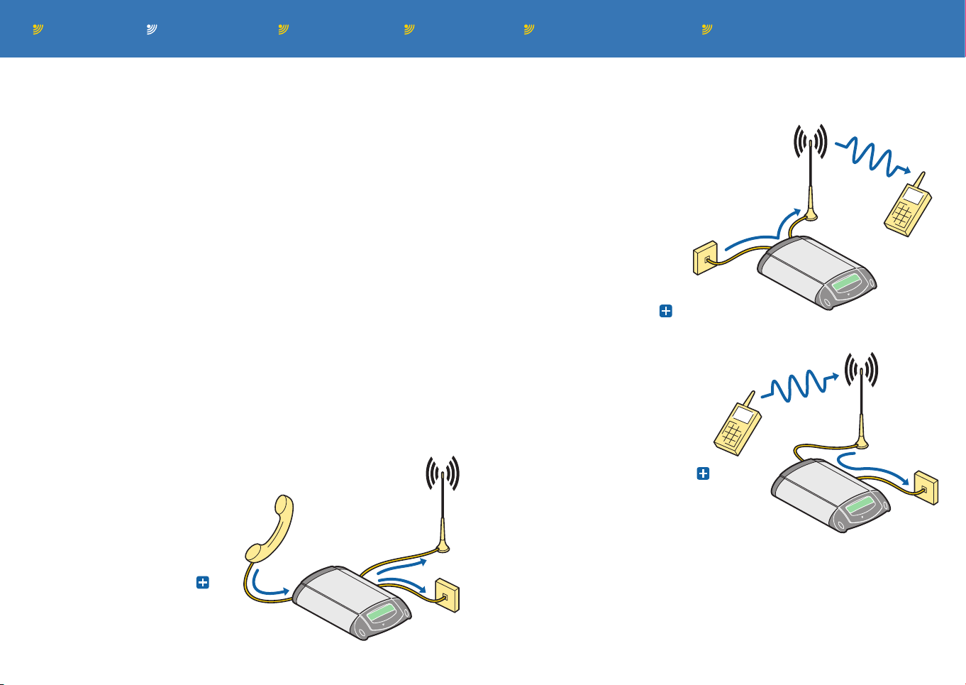
Things really get interesting when you consider the dual link ’L’
models of the Burnside T9 series. These are fitted with both a PSTN
(Public Switched Telephone Network) landline socket as well as a
mobile connection; a combination which can return potentially huge
savings on your call costs using the following special features:
Outgoing call routing
This feature determines the most cost
efficient way to route your outgoing
calls: Calls to mobiles are sent via
the mobile link; all other calls
leave via the landline. Thus, you
avoid paying unnecessary
charges to the networks to
convert the calls for you -
Forward landline (optional)
When you’re out and about, this feature
lets you forward incoming calls from the
landline connection via the mobile link
to your mobile phone. When both the
Burnside unit and your mobile are
fitted with paired SIMs, no call
charges will be incurred; unlike the forwarding charges
that are made by your telephone service provider to
achieve the same result -
Landline dial through (optional)
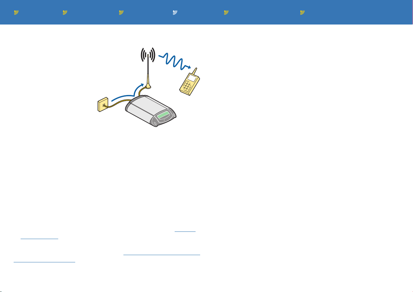
This feature allows an incoming call
from a mobile phone to make a new
outgoing call using the landline
connection. If you regularly dial
landline numbers from your
mobile this feature will prove to be
an invaluable cost saving tool -
The Burnside unit’s clear display and straightforward menu structure
mean all of these advanced features are easily available at any time.
Please note that this guide covers numerous versions of the unit.
Certain features may not be present in every version.
Page 4
Contents Introduction Operation Further informationInstallation Index page 3
7
8
9
4
5
6
1
2
3
0
#
BURNSIDE
Burnside
Teleco
m
Installation
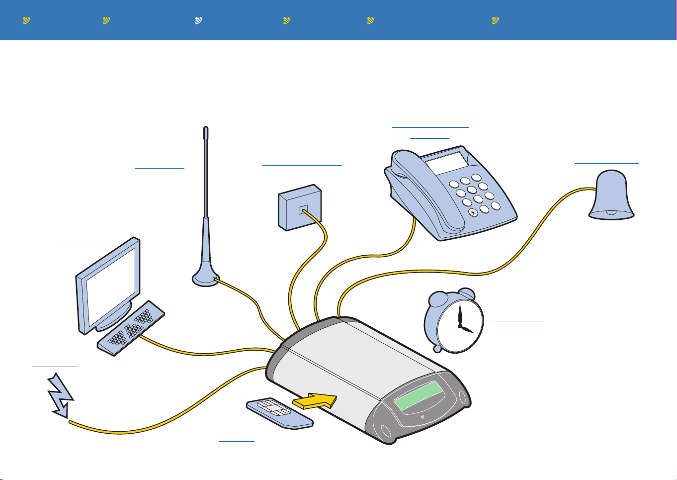
The Burnside T9 series units require several basic connections
and actions. This section provides details about how to get your
unit ready for operation.
Corded or cordless
telephone
Optional links to
external devices
Optional
computer link
Antenna link to
GSM or GPRS
network
Landline wall socket
(‘L’ models only)
Set the
internal clock
Power input
Insert your
SIM card
Positioning your Burnside unit
Place the unit in a suitable location,
but not directly next to your telephone
and at least one metre from the
intended antenna position, in order
to avoid interference. You will need
close access to both a mains power
socket and (for ‘L’ models) a working
telephone socket.
Page 5
Contents Introduction Operation Further informationInstallation Index page 4
Phone
Line
Phone
Line
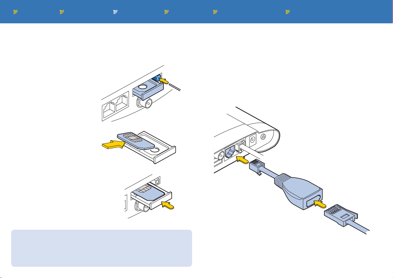
Inserting your SIM card
Note: Ensure that the unit is switched off before inserting your SIM
card. Insertion is most easily achieved with the unit carefully placed
upside down.
To insert your SIM card
1 Use a thin object to press
the tray eject button. Fully
remove the tray.
2 Place the SIM card into the
tray so that the contacts are
facing up.
3 Slide the tray back into the
slot and press it all the way in.
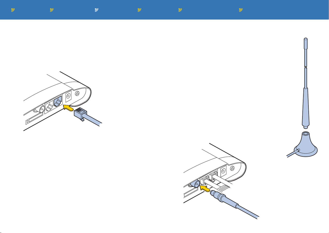
Connecting a telephone
The Burnside unit can be used with a touchtone corded phone, a
cordless DECT phone base station or a private branch exchange
(PBX), as required.
To connect a telephone
1 Connect the supplied cable adapter to the socket on the rear
panel, labelled ‘Phone’.
Note: Your phone may have a connector that fits directly into the
‘Phone’ socket, in which case the adapter is not needed.
Cable adapter
Phone
connector
SIM and Terminal PIN codes
The Burnside unit has its own Terminal PIN code which is different
from the PIN code used by the SIM card. The Terminal PIN is used
for certain control menu options and security procedures related
directly to the unit rather than the SIM card.
2 Connect your phone (or PBX) to the cable adapter.
Page 6
Contents Introduction Operation Further informationInstallation Index page 5
Phone
Line
Phone
Line
Connecting to a landline socket (‘L’ models only)
Dual link units can be connected to a standard landline wall socket in
order to allow least cost routing and call transfer features to be used.
To connect to a landline socket
1 Using the supplied phone cable, connect the smaller of the two
plugs to the socket on the rear panel, labelled ‘Line’.
Connection
to phone
socket
2 Connect the other end of the cable to a nearby telephone wall
socket. Note: Ensure that the cable does not cause a trip hazard.
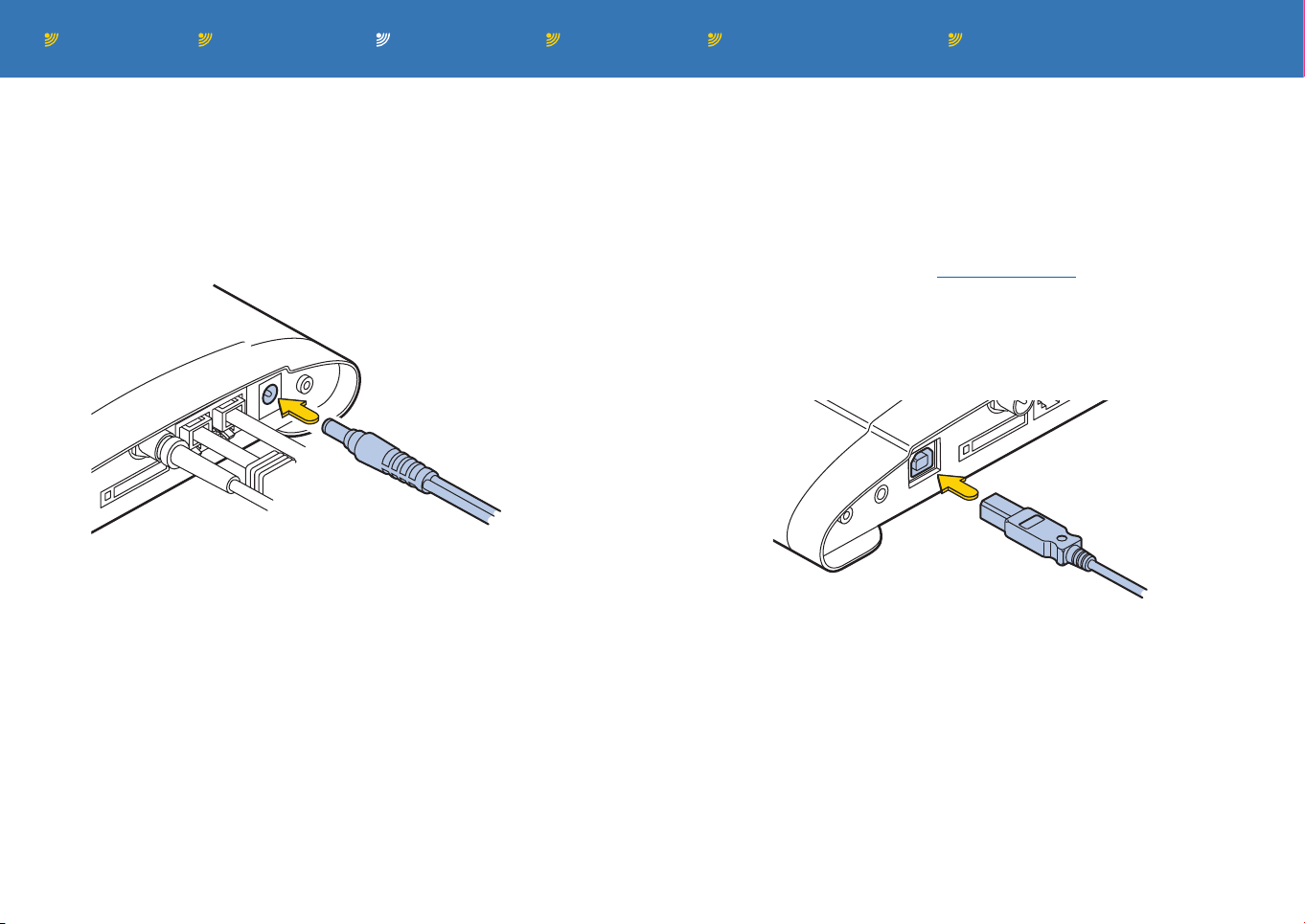
Connecting the magnetic mount antenna
The supplied antenna has a 3 metre cable to allow
it to be positioned well away from the unit and the
phone in order to minimise interference.
Note: The antenna base houses a strong magnet,
be sure to keep it away from monitor screens,
televisions, credit cards or any device affected by
magnetism.
To connect the magnetic mount antenna
1 Assemble the antenna by screwing the upper
section into the base until it is finger tight.
2 Position the antenna where required, if possible
on a secure metal surface.
3 Feed the antenna cable to the rear of the unit,
insert the connector into the antenna socket and
twist the collar until finger tight.
Note: Ensure that the cable does not cause a trip
hazard.
Antenna
connector
Page 7
Contents Introduction Operation Further informationInstallation Index page 6
Phone
Line
Phone
Li
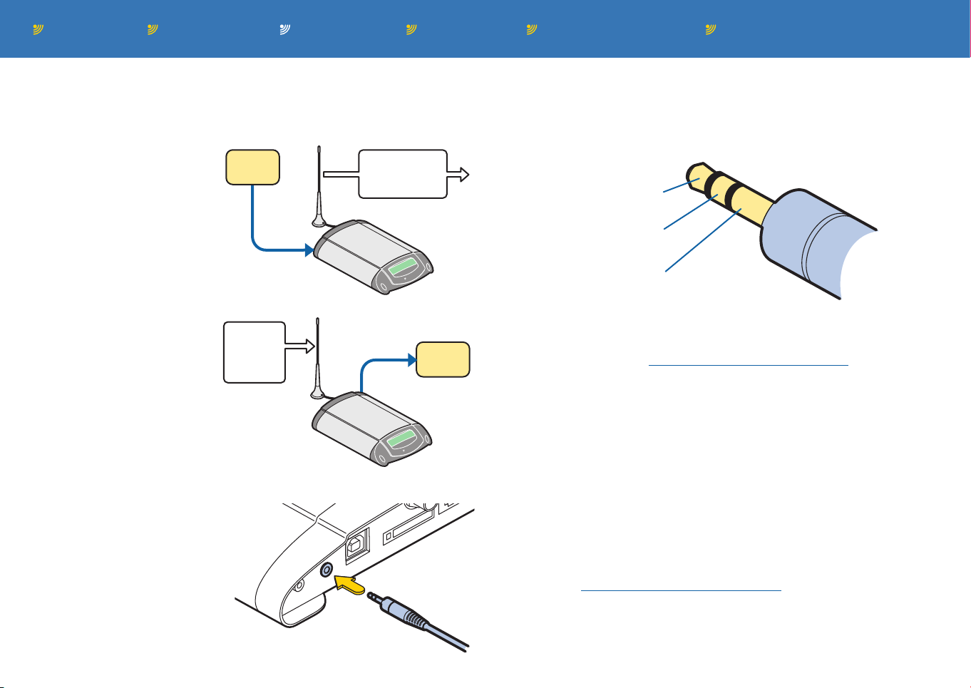
Connecting the power adapter
The supplied power adapter provides a stabilised 15VDC supply to
the unit.
To connect the power adapter
1 Attach the connector from the power adapter to the socket on the
far right of the rear panel.
Power adapter
connector
2 Plug the power adapter into a nearby mains outlet. The unit
will begin operation as soon as power is applied.
Note: Ensure that the cable does not cause a trip hazard.
Connecting to a computer (optional)
The unit includes a standard USB port in order to allow it to be linked
to a personal computer. Via the USB link, the unit may be used as a
GSM or GPRS modem, calls be initiated by TAPI compatible software and firmware updated.
Note: Install the software driver into your computer before connecting it to the Burnside unit - see Data connection for details.
To connect to a computer
1 Once the software driver has been installed on the computer, use
a USB type A to type B cable to link a vacant port on the computer to the socket on the Burnside unit.
USB connector
Page 8
Contents Introduction Operation Further informationInstallation Index page 7
External
device
Signal
input
Pre-prepared
text
message
BURNSIDE
Burnside
Telecom
External
device
Signal
output
Text
message
with
command
BURNSIDE
Burnside
Telecom
Phone
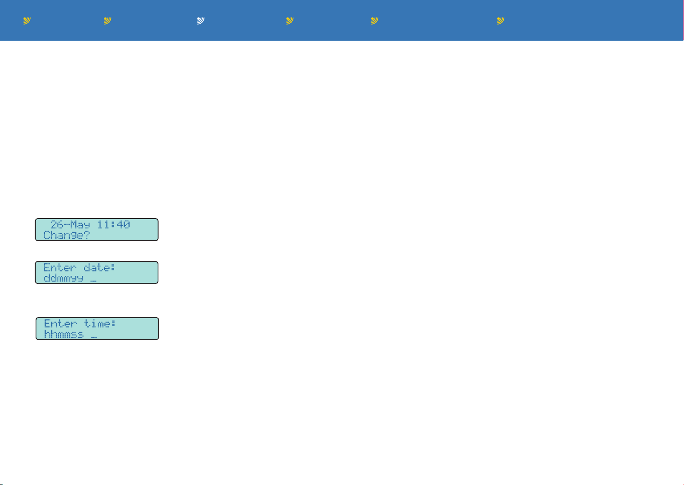
Connecting to external devices
The Burnside unit features a link port which allows it to connect to
external devices and either send, or respond to, switched signals.
Responding to an input
To wire the jack plug
Use a three way 3.5mm jack plug, wired as follows, to gain access
to both input/output circuits of the link port:
The unit can react to a
received input signal (for
Jack tip - Circuit 1
instance from an alarm system, a simple door switch,
etc.) and, in response, send
Jack ring - Circuit 2
out a pre-prepared SMS
text message warning to a
Jack sleeve - Ground
specific mobile number.
Switching an output
When a specially formatted SMS text message is
received, the Burnside unit
can generate a switched
output signal to trigger an
external device.
To connect an external device
1 Insert the 3.5mm jack plug
of the cable leading from
link port socket on the far
left of the Burnside unit’s
rear panel.
the external device, into the
• Circuit 1 can operate either as an input into the Burnside unit or
as an output from it, depending on how the unit is programmed
(using 0#54120 - see Using the input/output channels for details).
When set as an input, Circuit 1 responds to a high voltage of 2.4
to 5V and a low voltage of 0 to 0.8V.
When set as an output. Circuit 1 uses open collector switch-
ing which is suitable for providing a logic signal or driving a low
power relay providing the latter has an external power source as
well as suitable back-EMF protection to prevent damage to the
unit’s circuitry.
• Circuit 2 is fixed as an input to the Burnside unit.
Circuit 2 can sense and report nine distinct voltage levels, ranging
from 0.5V to 4.5V in 0.5V steps.
Using menu commands you can configure various aspects of both
circuits. See Using the input/output channels for details.
Page 9
Contents Introduction Operation Further informationInstallation Index page 8
Setting the internal clock
The internal clock of the Burnside unit keeps accurate time and is
maintained by an internal battery during power failures. The battery
is automatically charged while the unit is switched on (approximately
two days to reach full charge) and will last roughly thirty days without
a power input.
Note: Date stamping for landline calls is provided by the landline
caller ID mechanism. Caller ID from the incoming mobile side uses
the Burnside unit clock. To avoid confusion, ensure that the unit
clock is correctly set using the method shown here.
To set the internal clock
1 Lift the phone handset and dial 0#550. The display will show:
2 Press the 0 key to confirm. The display will show:
3 Using the phone keypad, enter the day, month and year. After the
sixth digit is entered, the display will show:
4 Enter the current time in hours, minutes and seconds. After the
sixth digit is entered, the display will return to the clock menu and
the information will be saved.
Page 10

Contents Introduction Operation Further informationInstallation Index page 9
Operation
This section covers the features of the Burnside
unit that you will use on a regular basis, such as: Ü
Making and receiving calls
Your Burnside unit is designed to make the attached telephone
operate as it would do if connected directly to a landline.
• Making and receiving calls
• Using the phonebook
• Text messaging
• Using the call register
• Call handling features
To make a call
1 Lift the handset and listen for the dial tone.
2 Dial the required number. Three seconds* after the final number is
entered, the call will be placed.
Note: For calls that use the mobile phone link, you must use the
full dialling code for all calls, even to those in your local area. On
‘L’ models (which have an additional landline connection), it is
best practice to also use the full dialling code as calls may be
directed via either connection method.
* The standard three second dial delay can be changed using
menu 0#5220 to a period between 1 second and 1 minute. When
entering a phone number, you can optionally press the phone’s #
key to begin the dialling process immediately.
To make an international call
1 Lift the handset and listen for the dial tone.
2 Press and hold the phone’s zero key until ‘+’ appears on the dis-
play of the Burnside unit.
3 Dial the standard international code for the required country (e.g.
‘44’ for the UK, ‘33’ for France, etc.) and then dial the required
phone number (omit the initial zero of the area code, as usual).
To end a call
1 Replace the handset. No other action is required.
To make a speed dial call
1 Lift the handset and listen for the dial tone.
2 Press the required speed dial number between 1 and 9, then
press the # button. The display will show the name of the phonebook entry stored at the chosen speed dial location and ask for
confirmation to dial.
3 Press the 0 key to dial.
To receive a call
When the phone rings, lift the handset and take the call in the usual
manner.
If the caller’s number is declared by the network, it will be shown
on the display of the Burnside unit and also that of the phone (if the
phone supports the Caller ID feature). Note: You can disable outgo-
ing Caller ID using menu 0#5240 - see Caller ID for details.
If the ‘Allow reject’ option is enabled on the Burnside unit (menu
0#5250 - see Allow reject for details), lift the handset and then press
the phone’s 0 key to accept the call.
Page 11
Contents Introduction Operation Further informationInstallation Index page 10
Using the Phonebook
The Phonebook uses your SIM card to store the names and numbers
of your contacts. You can add, edit, erase, search and dial those
stored details using a minimum of keypresses.
Phonebook contacts are listed alphabetically with the exception of
the first nine entries, which are reserved for speed dialling your most
commonly used numbers.
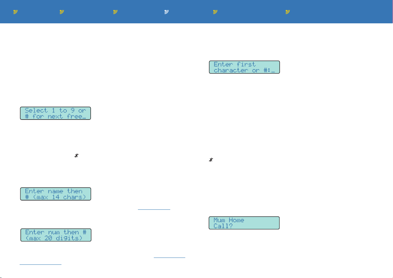
To add an entry
1 Lift the phone handset and dial 0#120. The display will show:
2 You can now either:
• Use one of the first nine (speed dial) memory locations: Press
a key between 1 and 9. If the location is already taken, the
display will show the name and ‘Replace?’. Press the 0 key to
proceed (or press to go back a step).
or
• Use the next vacant standard memory location: Press the # key.
The display will show:
3 Using the phone’s keys in a similar manner to writing a text, enter
the name of your contact and then press the # key.
The display will show:
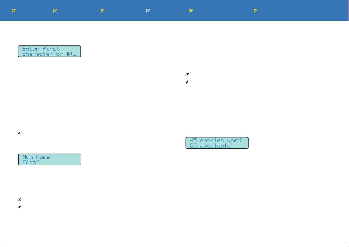
To call a standard phonebook entry
1 Lift the phone handset and dial 0#110. The display will show:
2 You can now either:
• Scroll through the list: Press the # key to display the first
memory location.
or
• Search by name: Press the phone key containing the first letter
of the contact’s name (if necessary, press the key repeatedly to
display the correct letter). The display will show the first entry
that has the chosen letter.
3 Use the phone keys as follows to scroll down, up or dial:
# to scroll down the list by one place,
to scroll up the list by one place,
0 to dial the entry that has the flashing cursor.
To call a speed dial phonebook entry
1 Lift the phone handset.
2 Press and hold a key (between 1 and 9) for roughly one second.
3 Release the key. After a short pause the display will show the
name of the chosen entry:
4 Enter the full phone number of your contact and then press the
# key. Note: For entering international numbers, see To make an
international call. The entry will be stored within SIM card memory.
4 Press the 0 key to dial the chosen contact, otherwise hang up and
start again to choose a different contact.
Page 12
Contents Introduction Operation Further informationInstallation Index page 11
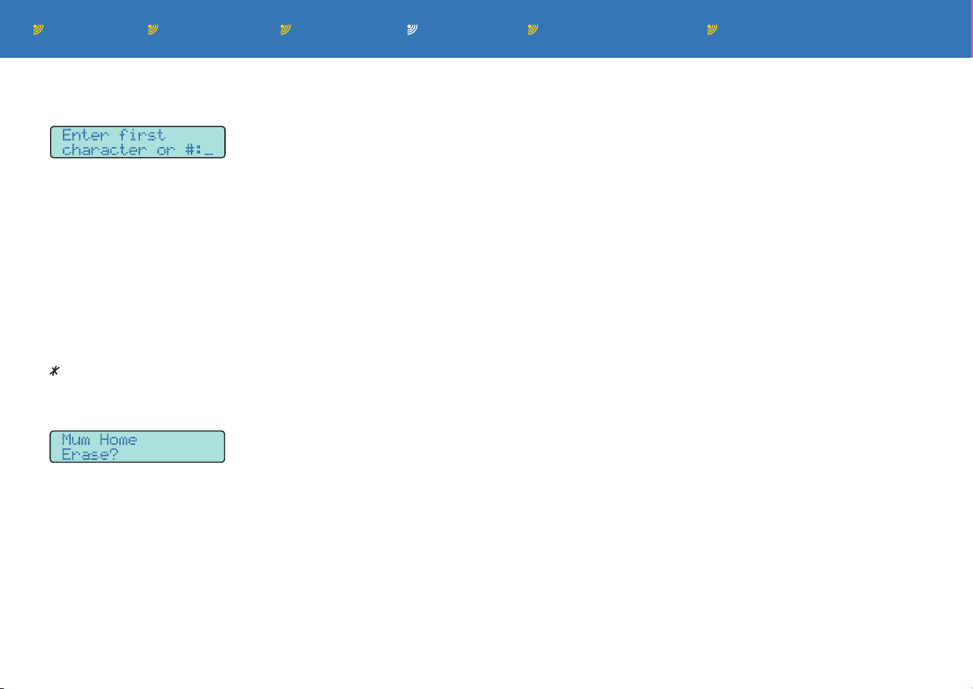
To edit a phonebook entry
1 Lift the phone handset and dial 0#130. The display will show:
5 When you have finished editing the name, press the # key repeat-
edly until the cursor exceeds the final character. The display will
now show the current number for the entry.
2 You can now either:
• Scroll through the list: Press the # key to display the first
memory location.
or
• Search by name: Press the phone key containing the first letter
of the contact’s name (if necessary, press the key repeatedly to
display the correct letter). The display will show the first entry
that has the chosen letter.
3 Use the phone keys as follows to scroll down, up or select:
# to scroll down the list by one place,
to scroll up the list by one place,
0 to select the entry that has the flashing highlight.
6 Use the phone keys as follows to edit the number:
# to move the cursor right one place,
to move the cursor left one place,
(press and hold) to delete the current digit,
0-9 Use the other keys to enter digits as usual.
7 When you have finished editing the number, press the # key re-
peatedly until the cursor exceeds the final character. The display
will briefly show ‘Saved’ and return to the Edit menu.
To check the memory status
1 Lift the phone handset and dial 0#140. The display will show how
many entries are used and available:
The display will show:
4 Press the 0 key again to confirm your choice. The entry name will
be shown on the lower line of the display with an underline cursor.
Use the phone keys as follows to edit the name:
# to move the cursor right one place,
to move the cursor left one place,
(press and hold) to delete the current character,
0 to replace the current character with a space (equivalent to de-
lete). You can also enter other punctuation marks with repeated
presses of the 0 key.
1-9 Use the other keys to enter characters as usual.
Page 13
Contents Introduction Operation Further informationInstallation Index page 12
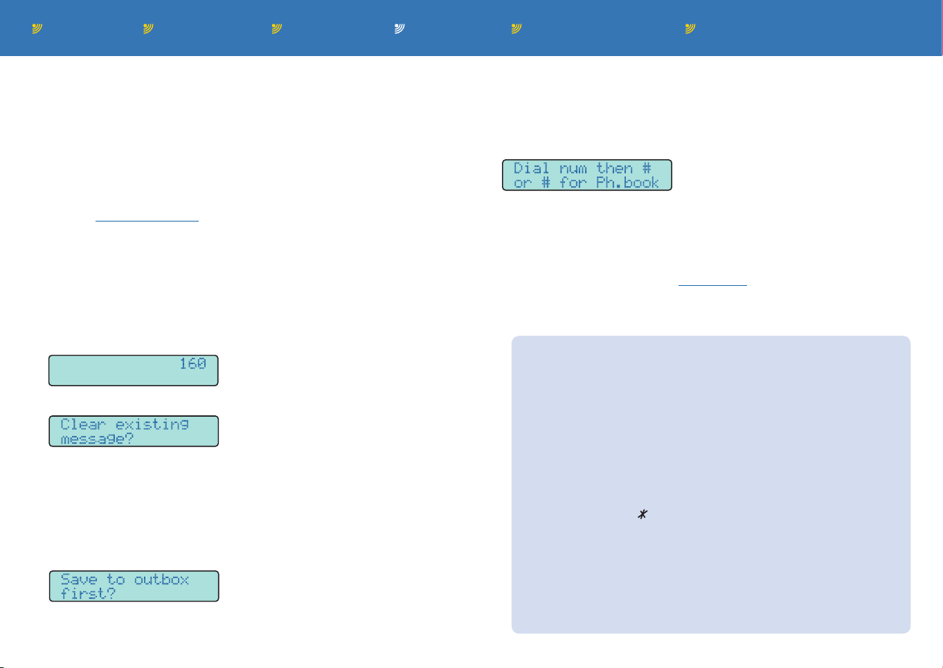
To erase an entry
1 Lift the phone handset and dial 0#150. The display will show:
You can now either:
• Scroll through the list: Press the # key to display the first
memory location.
or
• Search by name: Press the phone key containing the first letter
of the contact’s name (if necessary, press the key repeatedly to
display the correct letter). The display will show the first entry
that has the chosen letter.
3 Use the phone keys as follows to scroll down, up or select:
# to scroll down the list by one place,
to scroll up the list by one place,
0 to select the entry that has the flashing highlight.
The display will show:
4 Press the 0 key to confirm the erase operation.
Page 14
Contents Introduction Operation Further informationInstallation Index page 13
Text messaging
The Burnside unit provides SMS text messaging for messages up
to 160 characters in length. Inbox and outbox messages are stored
within the SIM card memory and the number of messages available
are determined by the capacity of the card. The most recently edited
text message, as well as messages related to the input port sensors,
are stored in non-volatile memory.
Note: The Auto delete SMS feature is enabled as standard on dual
link units. With this mode set, all incoming text messages will be
deleted and no indication of their arrival will be given. Use 0#24220
to disable the auto delete mode.
To write and send a message
1 Lift the phone handset and dial 0#210. Depending on whether an
existing message is held within the editor, the display will either
show:
No previous message stored, you
can start typing immediately.
or
Either press 0 to clear the existing
message or press # to retain and
edit it.
2 Enter your message (see Character and numeral editing Ü). The
counter in the top right corner shows the number of characters
remaining.
3 When your message is complete and the cursor is at the end of
the message, press #. The display will show:
You can use the outbox to optionally store messages that you wish
to keep, such as template messages or unfinished messages.
4 Either press the 0 key to save the message in the outbox (and
then continue automatically to addressing) or press the # key to
go straight to the addressing section. The display will show:
5 Either:
• Enter the recipient’s phone number and then press #. Then
press 0 to confirm that you wish to send, or
• Access the phonebook: Press # immediately and then use the
methods described in the phonebook section to locate the
required contact; then press 0 to select. When prompted, press
0 again to confirm that you wish to send.
Character and numeral editing
Use the phone keys 0 to 9 to enter characters.
Press a key repeatedly to go through the characters available
on that key. The choice of characters allocated to each key are
shown on the top line of the display. After a short delay or a
different key is pressed, the current character is accepted.
The 0 key is mainly used for the space character but also
includes other formatting characters.
Press and hold a key to change between upper and lower case.
Press and hold the key to delete a character.
Press and hold the # key to skip to the end of the message.
To store international phone numbers use the + character fol-
lowed by the country code. Enter + by holding down the 0 key.
If the terminal is on the move for example on a boat, we would
recommend using the full number including country code for
all phonebook entries.
Page 15
Contents Introduction Operation Further informationInstallation Index page 14
To read a received message
When one or more text messages are received, the display on
the Burnside unit will illuminate and announce the number of new
messages. Use the steps discussed below to access received
messages (new and previously read) at any time.
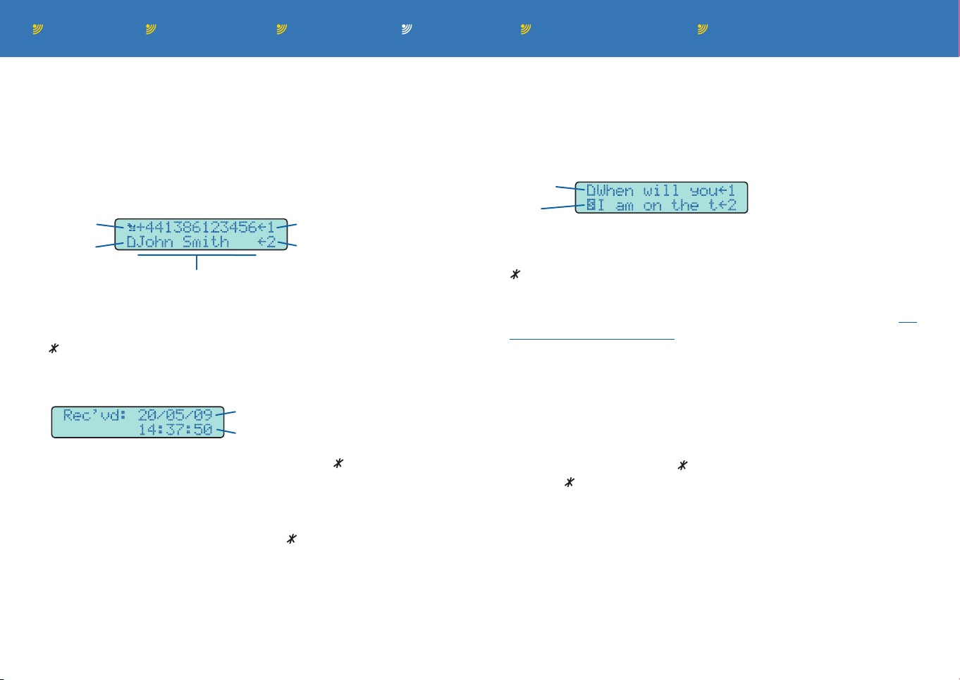
1 Lift the phone handset and dial 0#220. If any received messages
are held, the display will show:
Unread
Viewed
Sender’s phone number or name (if held in phonebook)
Latest message
Previously viewed message
2 Use the phone keys as follows to scroll down, up or select:
# to scroll down the list of messages by one place,
to scroll up the list of messages by one place,
0 to select the message entry that has the flashing highlight.
The display will show:
Date of message (dd/mm/yy)
Time of message (hh:mm:ss)
3 Press 0 to read the message, then use # and to move forwards
and backwards through the message, respectively.
When you reach the end of the message, press # once more to
show the prompt: ‘Delete SMS?’
Either press 0 to delete the message, to return to the message
or hang up the handset to leave the message within the inbox.
Note: When the inbox is full and new messages are waiting to be
received, an alert will be shown on the display to remind you to
delete read messages to make space for new ones (deleting messages from the outbox will also free up space).
To view the outbox
The outbox allows you to optionally store messages or message
templates that you wish to keep.
1 Lift the phone handset and dial 0#230. The first twelve characters
of each stored message will be shown on each line:
Unsent
Sent
2 Use the phone keys as follows to scroll down, up or select:
# to scroll down the list of messages by one place,
to scroll up the list of messages by one place,
0 to select the entry that has the flashing highlight.
3 Edit, address and send the chosen message as discussed in To
write and send a message.
Message settings
There are two main settings related directly to messaging:
‘Edit message centre number’ and ‘Auto delete SMS’.
The ‘Message centre number’ is determined by your service provider and stored on the SIM card. If you are instructed to change this
number, lift the phone handset and dial 0#2410, then use the phone
keys to enter a new number ( and # to move cursor left and right,
long press to delete a digit, # after last digit to exit and save).
The ‘Auto delete SMS’ feature (enabled as standard on dual link
units) is useful if you do not wish to receive incoming text messages
and thus prevents filling memory with unwanted ‘spam’ texts. Lift
the phone handset and dial 0#24210 to discover the current setting, 0#24230 to enable auto delete mode and 0#24220 to disable
auto delete mode. Note: When auto delete SMS mode is enabled, no
indication will be given of incoming messages and no retrieval prior to
deletion will be possible.
Page 16
Contents Introduction Operation Further informationInstallation Index page 15
Using the call register
The Burnside unit maintains records of incoming calls that are
missed or successfully received, as well as the most recently dialled
outgoing calls. The call register also provides the duration of the last
call and allows you to set limits for the collective duration of outgoing
calls (see Tariff timer functions).
To view call register records
1 Lift the phone handset and choose the required register:
• For missed calls (incoming calls that were not answered),
dial 0#310.
• For received calls (incoming calls that were answered),
• (units without landline option) dial 0#320.
• (units with landline option) Mobile calls, dial 0#3210.
• (units with landline option) Landline calls, dial 0#3220.
• For outgoing dialled calls (not via phonebook), dial 0#330.
In all cases, a list of numbers will be displayed and you can use
the phone keys as follows to scroll down, up or to dial entries:
# to scroll down the list of numbers by one place,
to scroll up the list of numbers by one place,
0 to dial the number that has the flashing highlight.
To erase the dialled list
1 Lift the phone handset and dial 0#340.
2 Press the 0 key to confirm.
To show durations
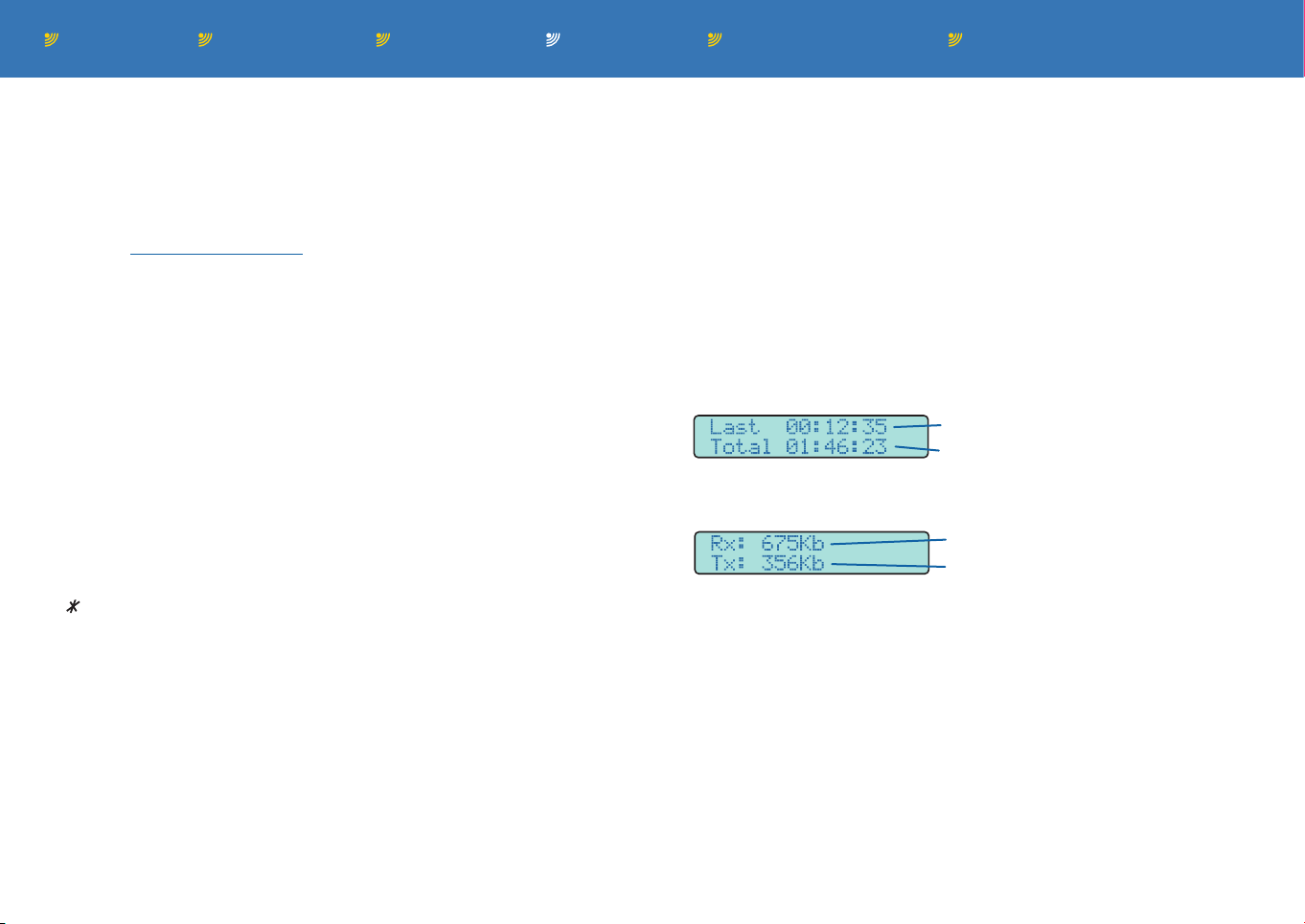
1 Lift the phone handset and dial 0#350. The display will show:
Duration of last call
Duration of all calls since manufacture
To show the GPRS log
1 Lift the phone handset and dial 0#360. The display will show:
Total data received
Total data transmitted
Note: The log is updated at the end of a GPRS session.
To clear the GPRS log
1 Lift the phone handset and dial 0#370. Then press 0 to confirm the
clear operation.
Note: If the SIM is changed, the registers will be automatically
erased. If the SIM is removed and then replaced, the registers will
remain unchanged.
Page 17

Contents Introduction Operation Further informationInstallation Index page 16
Tariff timer functions
Using call register information, the tariff timer function maintains
a record of outgoing call times and allows you to optionally set a
total limit on the duration of outgoing calls and also determine the
action(s) that should occur if the limit is exceeded. See also Method
for (tariff) timer reset and Restrict call time functions.
• View time used - dial 0#3810 - Shows the number of minutes used
since the tariff time count was reset.
• Set new tariff limit - dial 0#3820 - Sets the number of minutes for
the tariff that applies to the inserted SIM card. Valid entries are ‘1’
to ‘99999’ minutes, press # to save.
• Action taken at time limit (dial 0#3830) - This group of op-
tions determine what should happen when the tariff time limit is
reached. In all but the ‘Show status’ and ‘Set to no action’ options,
you can also arrange to send a pre-determined status SMS message to a designated phone number. This optional SMS message
function is fulfilled by the Channel 1 ‘Text to send’ facility (dial
0#55130).
• Show status - dial 0#38310 - Indicates the current action setting.
• Set to no action - dial 0#38320 - Determines that no action
should be taken when the tariff time limit is exceeded.
• Set to alert only - dial 0#38330 - When the tariff timer limit
is exceeded, the display will show the number of minutes
remaining or exceeded (and an optional text message can also
be sent to a specified number).
• Set to busy tone - dial 0#38340 - When the tariff timer limit
is exceeded, a busy tone will be output and the unit will
only accept outgoing emergency calls (and an optional text
message can also be sent to a specified number). Menu items
remain accessible.
• Set to open loop - dial 0#38350 - When the tariff timer limit
is exceeded, the unit will place the link to the connected
telephone into an open circuit (no voltage) condition and an
optional text message will also be sent (if one is stored using
the Channel 1 ‘Text to send’ facility (dial 0#55130)). This mode
is typically used when the unit is connected to a PBX (Private
Branch eXchange) trunk line. In this mode, the user interface
will no longer be accessible.
To remove the open loop condition, either send a text message
to reset the tariff timer (‘ppppre’ where pppp is the Terminal
PIN code - see Remote commands for more details) or temporarily remove power. When power is restored, the unit will no
longer be in open loop mode and the menu functions will be
accessible to reset the tariff timer or change the action. If no
changes are made, one more call can be made, however, when
that call is ended, the line will return to open loop. Incoming
calls will ring as normal and can be answered. At the end of the
call, the line will return to open loop.
• Set to use landline - dial 0#38360 - When the tariff timer limit
is exceeded, all outgoing calls will be routed via the landline
connection (this option is available only on units that include a
landline connection facility).
Page 18

Contents Introduction Operation Further informationInstallation Index page 17
Method for (tariff) timer reset
This group of options control how the tariff timer should be reset.
• Show status - dial 0#38410 - Indicates the current setting.
• Set to manual - dial 0#38420 - In this mode, the tariff timer can
be reset either by using the ‘Reset now’ option or by sending a
text message (reset the tariff timer) formatted as ‘ppppre’ where
pppp is the Terminal PIN code - see Remote commands for more
details.
• Set to automatic - dial 0#38430 - In this mode, the tariff timer will
be reset each new month at the start of the day specified using
the ‘Day of reset’ option.
• Day of reset - dial 0#38440 - Determines the day of each month
from which the tariff timer should reset (when the ‘Set to automatic’
option is set). Valid entries are ‘1’ to ‘28’, press # to save.
• Reset now - dial 0#38450 - Resets the tariff timer immediately. This
action can also be achieved by either temporarily removing power
from the unit or by sending a text message (reset the tariff timer)
formatted as ‘ppppre’ where pppp is the Terminal PIN code - see
Remote commands for more details.
Restrict call time
This group of options allow you to set a time limit that should not be
exceeded by any single outgoing call and also determine the action
that should occur if the limit is exceeded. The actions of these options are independent from those of the tariff timer.
• Set new time limit - dial 0#3910 - Determines the number of min-
utes permissible within a single outgoing call. Valid entries are ‘1’
to ‘60’ minutes, press # to save.
• Action taken at time limit (dial 0#3920) - This group of options
determine what should happen when the restrict call time limit is
reached.
• Show status - dial 0#39210 - Indicates the current setting.
• Set to no action - dial 0#39220 - Disables the restrict call time
feature. The Show durations option will still show the time of the
last call when selected.
• Set to end call - dial 0#39230 - When selected, the call will
be automatically terminated when the restrict call time limit is
reached. If this option is selected, the recall/flash call control is
automatically disabled. See Allow recall/flash (0#5270).
Page 19
Contents Introduction Operation Further informationInstallation Index page 18
BURNSIDE
Burnside
Telecom
OR
Call handling features
This section presents a number of separate call handling features
that help to make the Burnside units which have dual links (mobile
and landline) the most flexible and beneficial in their class.
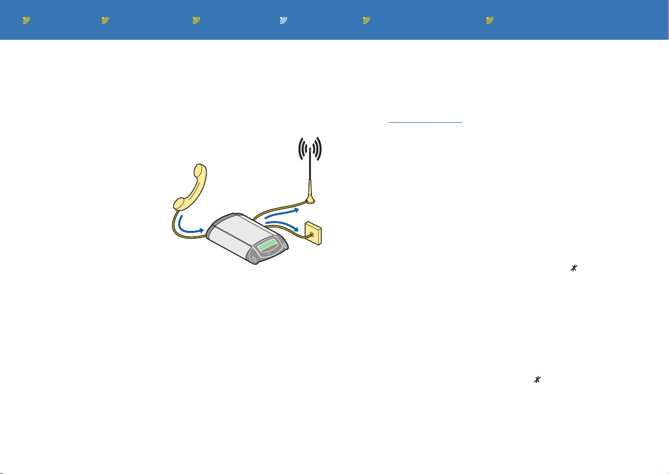
Outgoing call routing (‘L’ models only)
This feature has the potential to
greatly reduce your call costs by
ensuring that outgoing calls are
made using the most efficient
method:
• Calls to fixed phones via the
landline connection,
• Calls to mobiles via the mobile connection.
To use outgoing call routing you
merely need to enable the feature and, if necessary, redefine
the call prefix for mobile numbers (‘07’ as standard).
• Show status - dial 0#9110 - Indicates the current setting.
• Set to match prefix - dial 0#9120 - Enables outgoing call routing
via the most efficient method.
• Set to route all calls - dial 0#9130 - Sends all calls only via the
mobile connection.
• Set to route no calls - dial 0#9140 - Sends all calls only via the
landline connection.
• Prefix of mobile numbers - dial 0#920 - Use this option to optionally change the standard mobile prefix (usually 07). All dialled
numbers beginning with these two digits will be routed via the
mobile connection when the feature is enabled.
Manually selecting a landline connection
Use the following technique to force the unit to use the landline connection rather than the mobile link for the next call (‘L’ models only).
Note: The Allow recall/flash (0#5270) option must be enabled before
you can use tapping the hook switch as a means of control.
• After lifting the handset, press the recall button on the phone (or
quickly tap the hook switch) to make a direct connection via the
landline.
Manually routing a landline call via mobile connection (‘L’ models only)
This feature allows you to transfer an existing landline call out to a
new number via the mobile connection. Think of this feature as your
own mini-PBX (Private Branch eXchange), allowing you to connect
two remote callers whenever required.
1 During a call (via the landline connection), press 9 on the phone.
The existing call will be placed on hold and you will hear a dial
tone.
2 Dial the complete phone number to which you wish to transfer the
existing call. Once the called number is ringing, you can either
hang up immediately (to directly connect the calls) or wait for an
answer in order to introduce the landline caller before hanging up.
• If necessary, press recall on the phone (or quickly tap the
hook switch) to display the options for rejecting the new call or
swapping to the existing call. Use the or # keys to choose the
required option and press 0 to accept.
Note: Once the call is transferred, you will continue to be charged
by your mobile service provider for the duration of the new call.
Page 20
Contents Introduction Operation Further informationInstallation Index page 19
BURNSIDE
Burnside
Telecom
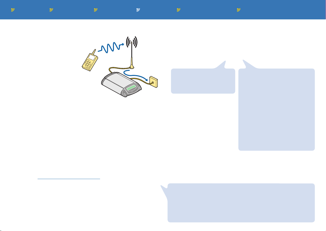
Landline dial through (‘L’ models only)
This feature allows an incoming call
received via the mobile connection to make a new outgoing call
using the landline connection.
This ability provides great cost
savings when you need to
regularly dial landline numbers
from your mobile. Cost savings
will be particularly effective if your
mobile phone and the Burnside unit
are both fitted with paired SIMs (which incur
no charges for calls made between them).
In use, when the Burnside unit answers the incoming call it will either
sound a beep to indicate that a PIN code is required or will give a
dial tone, depending on the selected mode.
Controlling this feature using phone button presses
The unit will respond according to how the options have been set:
• Show status - dial 0#9610 - Indicates the current setting.
• Set to match phonebook - dial 0#9620 - When set, only incoming
calls from phone numbers registered within the phonebook will be
permitted to make outgoing dial through calls.
• Set to use PIN - dial 0#9630 - When set, an incoming caller who
wants to make a dial through call, will need to enter a valid PIN
code (the Terminal PIN, not the SIM PIN) followed by #. If the PIN is
correct the landline dialtone will be heard, otherwise the call will end.
• Set to allow any caller - dial 0#9640 - When set, any incoming
caller will be permitted to make a dial through call and will be
presented with the landline dial tone.
• Set to bar dial through - dial 0#9650 - Disables the dial through.
• To follow on a new call without dialling back into the unit - dial
## to clear the current landline call and allow a new call to be made.
Controlling this feature using remote text commands
• Send an SMS message to the unit, formatted as follows:
ppppcc
The first 4 characters (pppp)
must be the terminal PIN
(1234 as standard, 0#51240
to change).
The unit will normally respond
by sending an SMS message
back to the number that sent
the command. The response
is either the new status of the
unit or an error message if the
command is not recognised. If
required, you can suppress the
reply by placing a fullstop after
the PIN, e.g. 1234.Id will enable
dial through without replying.
Note: It is not possible to guarantee that an SMS will be delivered immediately and there are rare occasions when the message will not be
sent at all.
IMPORTANT: Reliable operation of the dial through is dependant on the
quality of the connection. If the quality of the connection is poor, a wrong
number could be dialled inadvertently. If there is doubt about the quality,
use the PIN entry mode which will give a good indication that the connection is good enough to accept the PIN number. Calls originating from a
mobile phone should generally be the most reliable due to the way those
dialling tones are created by the network equipment.
Immediately after the terminal PIN
(no space), include the first two
characters (cc) of the appropriate
command:
• IDENTITY Enables dial through
only for callers who are listed
within the phonebook.
• PIN Enables dial through and
requires PIN entry.
• NO Disables the dial through
feature.
Note: The command characters
are not case sensitive.
Page 21
Contents Introduction Operation Further informationInstallation Index page 20
BURNSIDE
Burnside
Telecom
Forward landline (‘L’ models only)
This feature allows you to automatically forward incoming calls received on the landline
connection to a specified remote number,
via the mobile connection. This ability provides great cost savings when you need to
regularly transfer incoming calls from
your fixed phone to your mobile
by avoiding service provider
forwarding charges. This
feature is particularly cost
effective when your mobile
phone and the Burnside unit
are both fitted with paired SIMs (which incur no charges for calls
made between them).
You can choose to allow the locally connected phone to ring (and intercept the call) before or during the forwarding process or carry out
forwarding without ringing the local phone. You can also determine
other settings to suit your requirements.
Notes:
• When using this feature, you are recommended to always have
a voicemail facility on the mobile phone (to which calls are being
forwarded) as a fall back option, in case the network is unable to
deliver calls.
• A text alert option is available to warn you if a call failed to be forwarded to the mobile phone or its voicemail facility - see Missed
call SMS alert for details.
Certain aspects of this feature can be controlled remotely using
specially formatted text messages - see Controlling this feature using
remote text commands for details.
Controlling this feature using phone button presses
The unit will respond according to how the options have been set:
• Show status - dial 0#4210 - Indicates the current setting.
• Enter number to forward to - dial 0#4270 - Allows you to declare
the phone number to which calls should be forwarded.
Note: You need to set the number to which calls will be forwarded
before choosing the forwarding mode. Remember to include the
dialling code at all times.
• Set to ring and forward - dial 0#4220 - The connected phone
will ring and the call forwarding process will begin to the remote phone number set by (0#4270). If a delay has been set by
(0#42810) then the specified number of rings must elapse before the call is actually forwarded. In the meantime, if the call is
answered by the locally connected phone, then the forwarding
process will end.
• Set to only forward - dial 0#4230 - All calls are forwarded without
the locally connected phone ringing.
• Set to announce, ring & fwd. - dial 0#4240 - The connected
phone will ring and the call forwarding process will begin to the
remote phone number set by (0#4270). Meanwhile a pre-recorded
prompt “Please wait for your call to be connected” will be played
repeatedly to the caller. If a delay has been set by (0#42810)
then the specified number of rings must elapse before the call is
actually forwarded. In the meantime, if the call is answered by the
locally connected phone, then the forwarding process will end.
• Set to announce & forward - dial 0#4250 - The incoming call
will be forwarded to the remote phone number set by (0#4270).
Meanwhile a pre-recorded prompt “Please wait for your call to
be connected” will be played repeatedly to the caller. The locally
connected phone will not ring.
continued
Page 22

Contents Introduction Operation Further informationInstallation Index page 21
Forward landline (continued)
• Cancel forwarding - dial 0#4260 - Only the local phone will ring.
• Forward options (dial 0#4280):
• Set num extra rings delay - dial 0#42810 - Allows you to
specify how many times the locally connected phone should
ring before the forwarding action begins - applicable to modes
0#4220 and 0#4240 only). The default setting for this feature is 0
(i.e. start forwarding immediately).
• Missed call SMS alert - dial 0#42820
If an incoming landline call fails to be connected with the
forwarded destination number (due to weak coverage, network congestion, etc.), this feature will send a text message to
that number with a list of missed calls, the same as the ‘Who’
remote command. If the network connection is temporarily lost,
the alert message will be sent once the connection is re-established.
Note: If the phone at the forwarding number was unavailable,
causing the network to divert the call to voicemail, then a message would not be sent by the Burnside unit because (from its
perspective) the forwarding operation was successful.
• Show status (dial 0#428210) - Indicates the current setting.
• Alert for any call (dial 0#428220) - Send a text message
whenever an incoming call is not successfully forwarded.
• Alert for call with ID (dial 0#428230) - Send a text message
only when an incoming call (which provides its number) is not
successfully forwarded.
• No missed call alert (dial 0#428240) - Disables the feature.
• Prompt test - dial 0#42830 - Allows you to hear the announce-
ment that will be played to callers while forwarding takes place.
Controlling this feature using remote text commands
• Send an SMS message to the unit, formatted as follows:
ppppccffffffff
The first 4
characters
(pppp)
must be
the terminal PIN
(1234 as
standard,
0#51240 to
change).
The unit will normally respond by sending an SMS message back to
the number that sent the command. The response is either the new
status of the unit or an error message if the command is not recognised. If required, you can suppress the reply by placing a fullstop
after the PIN, e.g. 1234.Fo will set forwarding without replying.
After the terminal PIN (no space),
include the first two characters
(cc) of the appropriate command:
• FORWARD Set call forwarding
to the number specified and
ring the local phone.
• SILENT As per FORWARD
except local phone will not ring.
• RING As per FORWARD with
an announcement to the caller.
• ANNOUN As per FORWARD
with a caller announcement but
no ringing of the local phone.
• CANCEL Cancels call forwarding.
Note: The two command characters are not case sensitive.
After the command, enter
number (ffffffff)
to forward to.
If no number
is given, unit
will use the
last number
specified. If no
last number is
stored, it will
return an error
message.
When specifying international
num, use format
+nn12345678.
Where nn is the
country code.
Page 23

Contents Introduction Operation Further informationInstallation Index page 22
Answering a landline call during a mobile call
When a call is in progress over the mobile network, an incoming
call over the landline will cause three short beeps to be heard in the
handset and the caller identity will be shown on the display. There
are several options.
• Replace the handset to discard the mobile call and lift it again to
accept the landline call.
• Press the recall button on the phone (or quickly tap the hook
switch) followed by the 0 key to accept the landline call and put
the mobile call on hold.
• Press recall on the phone (or quickly tap the hook switch) again to
display the options for rejecting the held call or swapping to the
previous call. Use the or # keys to choose the required option
and press 0 to accept.
Aborting fax or data calls
If a data call or fax call is in progress between the unit and a connected computer, it is not possible to make a voice call at the same
time. However it is possible to abort the data/fax call using the following procedure:
1 Lift the handset and attempt to make an outgoing call, for exam-
ple by dialling 01. The unit will immediately indicate it is not possible to dial a voice call by displaying “Busy, hang up” and emitting
a busy tone.
2 Press the recall button on the phone (or quickly tap the hook
switch) which will cause the display to show “Abort data/fax?”
3 Press 0 to end the data or fax call.
Incoming calls during menu access
If an incoming call is received during interaction with user functions,
for example editing the phone book, a ringing tone will be heard
through the handset. When the handset is replaced, the phone will
ring and the call may be answered in the normal way.
Page 24

Contents Introduction Operation Further informationInstallation Index page 23
Network call features
Note: The availability of these options are dependant on the SIM
card and service provider. If a service is not provided, a message
such as “operation not supported” or “ss not executed” where ss
means Supplementary Service.
Call diverting
These call divert options control the service provided by your mobile
network, which will transfer incoming voice calls to a separate phone
number when the Burnside unit cannot take calls (for a variety of
different reasons). The various divert options are not mutually exclusive, so you can arrange different or the same divert numbers for
any or all conditions, as required. Each divert option has three sub
menus: Status, Activate and Cancel.
When activating a divert, a destination number must be either entered or chosen from the phonebook. This number is then registered
with your network provider.
When cancelling a divert, the previously registered number will be
retained by the network. When reactivating the same divert, you will
be given the choice to continue with the registered number or delete
it and replace it. To just delete it, hang up after deleting.
• Divert all - dial 0#4110 - All voice calls will be diverted.
• Divert when busy - dial 0#4120 - Voice calls will be diverted when
the phone is busy.
• Divert no answer - dial 0#4130 - Voice calls will be diverted if not
answered within 20 seconds.
• Divert when off - dial 0#4140 - Voice calls will be diverted whenever the unit is switched off or unavailable. See also Disconnect
from network.
• Cancel diverts - dial 0#4150 - Call diverting will be disabled.
Call waiting
When call waiting is supported by your network and enabled (see
menu codes below or Star hash codes), a call waiting situation will
occur if an incoming call is received while the unit is engaged in an
existing call. When this happens, the number or name (if identified
in the phonebook) will be displayed with “Waiting” shown and also a
short tone can be heard in the handset.
• Show status - dial 0#53210 - Indicates the current setting.
• Activate - dial 0#53220 - Enables the call waiting feature, subject
to network support.
• Cancel - dial 0#53230 - Disables the call waiting feature.
When enabled and a new call is received, you have the following
options:
• Ignore the tone and message, and wait until the caller either
hangs up or is diverted to voicemail, if enabled.
• Press the recall button on the phone (or quickly tap the hook
switch). The display will show “Accept & hold?” with the waiting
number/name on the second line. Either:
• Press 0 to place the original call on hold and accept the new
call, or
• Press # to display “Reject?”. Then press 0 to reject the waiting
call and return to the original call. Alternatively, press # to redisplay the “Accept & hold?” prompt, or
• Press the recall button (or quickly tap the hook switch) to return
to the original call.
Page 25
Contents Introduction Operation Further informationInstallation Index page 24
Call(s) held and multiparty (conference) calls
Note: Multiparty calls are supported only on non-’L’ models.
If one or more calls are held after accepting a waiting call or dialling
another number, you have the following options:
• Press the recall button on the phone (or quickly tap the hook
switch). The display will show “Reject?”. Either:
• Press 0 to reject the current active call and return to the held
call(s), or
• Press # to display “Add?”. Then press 0 to add the held call(s)
to the current call and provide a multiparty call, or
• Press # twice and the display will show “Swap?”. Press 0 to
place the existing active call on hold and connect to the held
call(s).
Note: If you try to add a party to a multiparty call and the call is answered by voicemail, you should disconnect the call, otherwise the
conference may be recorded by voicemail until it becomes full.
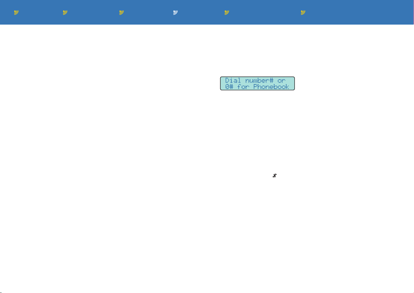
In-call dial
If during a call, you want to make another call without ending the
current call, follow this procedure:
1 Press the recall button on the phone (or quickly tap the hook
switch) and the display will show:
2 Dial the number, speed dial or use the phonebook and the call will
be connected in the normal way. Once connected, the display will
show ‘1 active call’ as well as the number of held calls.
• If it is not possible to connect the call, e.g. the line is busy or
there’s no reply, you will be automatically returned to the held
call(s).
• If the new call is connected, use the Call Held options (as
discussed on the left) to either reject, create a multi-party call or
switch between calls.
Notes: During in-call option selection, to return to a previous
option press the key. Hanging up the phone will terminate all
calls (held, calling, active or waiting).
Page 26

Contents Introduction Operation Further informationInstallation Index page 25
Further information
This section contains a range of further information arranged as a
series of appendices.
• Appendix 1: Menu options
• Appendix 2: Data connection
• Appendix 3: Using the input/output channels
• Appendix 4: Remote commands
• Appendix 5: Star hash codes
• Appendix 6: Advanced configuration codes
• Appendix 7: SMS key characters
• Appendix 8: SIM security features
• Important safety information
Contacting Burnside Telecom
For any technical queries regarding your T9 series unit, please
contact our technical support department:
• Email: [email protected]
• Tel: +44 (0)8700 762766 (extension 3)
• Fax: +44 (0)1420 520029
• Address: Burnside Telecom Limited,
Burnside House,
Isington,
Alton,
GU34 4PP,
United Kingdom.
Page 27
Contents Introduction Operation Further informationInstallation Index page 26
Appendix 1: Menu options (list)
Most features of the Burnside unit are accessed and configured
using the options contained within the menu.
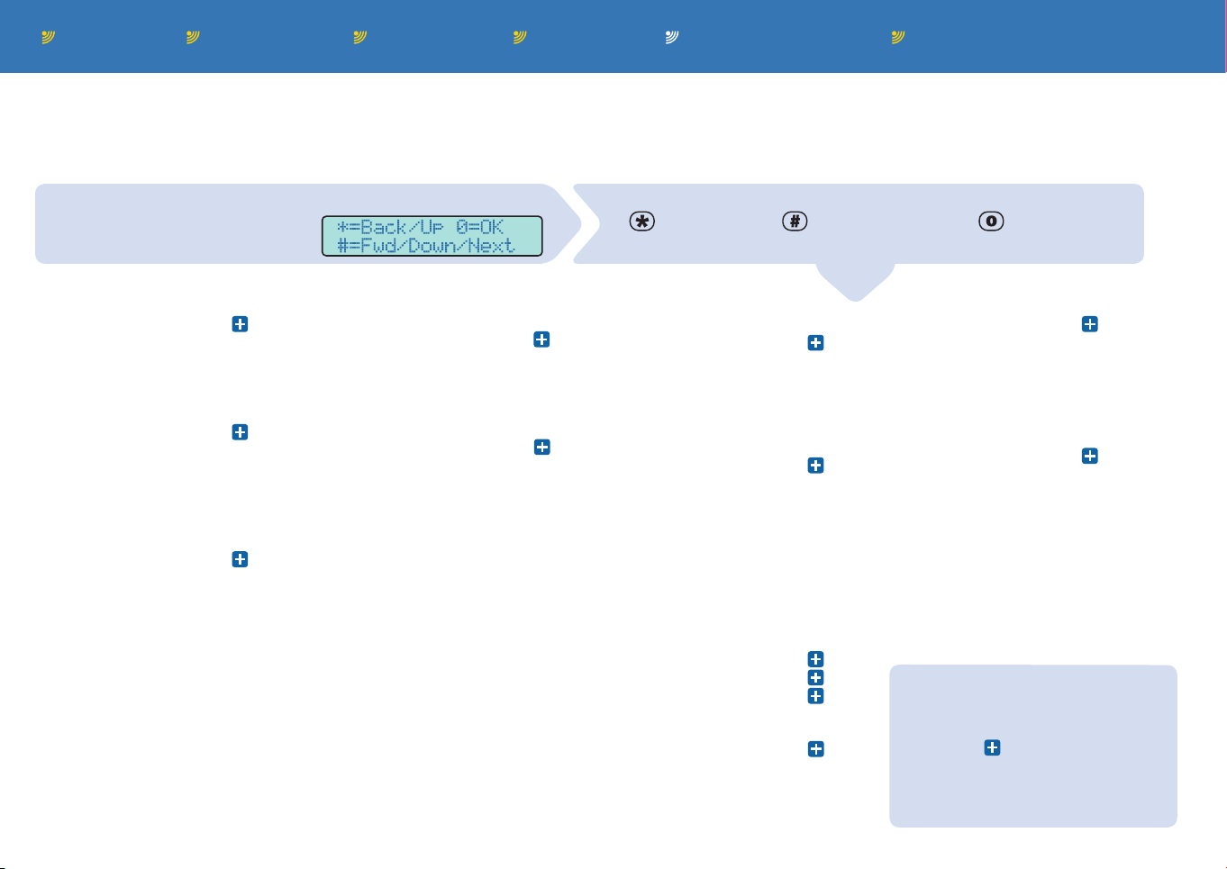
To use the menu
Lift the handset and press 0# on
the phone to enter the menu Ü
• Navigate the menu using these control keys:
to go back/up; to go down/forward; to enter/confirm
• Or enter a code to reach a particular menu item:
1 Phonebook
11 Search
12 Add entry
13 Edit
14 Status
15 Erase
2 Messages
21 Write message
22 Inbox
23 Outbox
24 Message settings
241 Edit message centre num
242 Auto delete SMS
3 Call register
31 Missed calls
32 Received calls
33 Dialled numbers
34 Erase dialled list
35 Show durations
36 Show GPRS log
37 Clear GPRS log
38 Tariff timer functions
381 View time used
382 Set new tariff limit
383 Action taken at time limit
384 Method for timer reset
39 Restrict call time
391 Set new time limit
392 Action taken at time limit
4 Divert & forward
41 Mobile network divert
411 Divert all
412 Divert when busy
413 Divert no answer
414 Divert when off
415 Cancel diverts
42 Forward landline
421 Show status
422 Set to ring & forward
423 Set to only forward
424 Set to announce, ring & fwd.
425 Set to announce & forward
426 Cancel forwarding
427 Enter number to forward to
428 Forward options
5 Settings
51 Terminal settings
511 Display contrast
512 Security settings
513 Service settings
514 Restore factory settings
515 TAPI voice mode
516 Tone region selection
52 Phone settings
521 Own number sending
522 Dial delay
523 Alert settings
524 CLI type
525 Allow reject
526 Change volume
527 Allow recall/flash
528 End of call signal type
529 Call progress announce
53 Network settings
531 Network selection
532 Call waiting
54 Input/Output settings
541 Channel 1
542 Channel 2
55 Set clock
6 Special function
61 Lock outgoing calls
62 Lock menu functions
63 Monitor inputs
64 Disconnect from network
7 Reserved
8 Help
9 Outgoing call routing
91 Calls via mobile networks
92 Prefix of mobile numbers
93 Landline IDD access code
94 Use landline prefix
95 Change landline prefix
96 Dial through control
Notes:
• Only the first three levels of menu
items are shown here.
• Click the icon for a section to
view further details for each option.
• Items shown in Blue are applicable
only to dual link ‘L’ models.
Page 28

Contents Introduction Operation Further informationInstallation Index page 27
Menu options (explanations)
This section provides explanations for all of the menu options that
are not dealt with elsewhere within this guide. Where options are
covered in other sections, the adjacent links will take you straight to
the relevant pages:
Phonebook (0#10) - See Using the phonebook for details.
Messages (0#20) - See Text messaging for details.
Call register (0#30) - See Using the call register for details.
Mobile network divert (0#410) - See Call diverting for details.
Forward landline (0#420) - See Forward landline for details.
Settings (0#50) - See below:
Terminal settings (0#510)
• Display contrast (0#5110) - Allows you to adjust the display to suit
your surrounding. Use the and # keys to change the contrast of
the display and press 0 to save the setting.
Security settings (0#5120)
• SIM PIN state (0#51210) - Use to specify whether the SIM PIN is
required. If enabled, the SIM PIN will be required every time the
unit is powered up or logged on.
If the SIM PIN is incorrectly entered, the number of tries remain-
ing (3 in total) is displayed. If the number of tries expires, the PUK
(PIN Unblocking Code - available from your service provider) will
be required and this must be entered using the **05* code.
• Change SIM PIN (0#51220) - Allows a new SIM PIN to be set. The
old PIN is first requested followed by the new PIN, which also
needs to be repeated. If the OLD PIN is incorrectly entered, the
security measures apply (as described above).
• Terminal PIN state (0#51230) - Specifies whether the terminal PIN
is required. The terminal PIN is used to prevent unauthorised use
of the terminal and also for remote monitoring and control functions. If the terminal PIN is enabled, the unit will request the PIN
when power is applied or if the remote monitoring and control
commands are being used.
• Change terminal PIN (0#51240) - The old terminal PIN must be
entered correctly, then the new PIN needs to be entered twice
before it is accepted. The PIN is fixed to 4 digits in length and is
set at manufacture to 1234
• Auto SIM unlock (0#51250) - When enabled, the unit can auto-
matically unlock the SIM at each startup (the SIM PIN must be
manually entered once after enabling).
continued
Page 29

Contents Introduction Operation Further informationInstallation Index page 28
Service settings (0#5130)
• Signal test (0#51310) - Displays the current signal strength
expressed in both logarithmic form (dBm) and as a percentage
roughly equivalent to the actual received signal level compared to
the practical minimum, divided by the possible maximum range
multiplied by 100.
• Show voltage (0#51320) - Displays the voltage level being sup-
plied by the connected power adapter.
• HR codec control (0#51330) - Controls the use of the HR codec
(half rate coder/decoder) used for speech transfer across the
mobile network. This setting is normally set to ‘Enabled’.
• PSTN detection control (0#51340) - (‘L’ models only) This setting
allows the unit to test for the presence of a valid PSTN landline
connection before dialling outgoing calls. If the link is not valid,
the call will be automatically placed on the mobile connection.
• No test (0#513420) - When set, the unit will not test for a valid
loop current, but will take the line off-hook and dial out using
the landline.
• Test loop (0#513430) - When set, the unit will take the line off-
hook, check for loop current (power supplied by the line) and if
current is present, it will dial the number using the landline.
• Loop & tone (0#513440) - When set, the unit will first check for
loop current and (if found) then check for a dial tone. If both are
present, then it will dial the number using the landline.
• Restore factory settings (0#5140) - See Restore factory settings.
• TAPI voice mode (0#5150) - When this option is selected, a con-
nected computer may dial the number using standard TAPI compatible software diallers. When a call is initiated by the computer,
the local phone will ring for ten seconds to allow the user to make
the call. If the phone is not picked up, the call is cancelled. When
the TAPI option is not set, the dialling command protocol via the
USB link is compliant with GSM specifications.
• Tone region selection (0#5160) - Selects the style of tones that
will be heard via the phone earpiece. On ‘L’ models, this also
determines the tone cadence expected from the network for end
of call detection.
• Show current setting (0#51610) - Indicates the chosen tones.
• Set to GB (UK) (0#51620) - Use UK standard tones.
• Set to IE (Eire) (0#51630) - Use Eire standard tones.
• Set to NL (Netherlands) (0#51640) - Use Dutch standard tones.
Phone settings (0#520)
• Own number sending (0#5210) - Determines whether your tel-
ephone number is sent via the network (Calling Line Identity, CLI
or Caller ID) to the person you are calling. The outgoing Caller ID
can also be temporarily suppressed (for one call) by first entering
#31# or can be enabled for a single call by first entering *31#.
• Dial delay (0#5220) - Sets the delay to elapse, after entering the
last digit, before starting to dial. The range is 1 second to 1 minute
and the factory setting is 3 seconds. When dialling, the call can
be started immediately by entering # at the end of the number.
continued
Page 30

Contents Introduction Operation Further informationInstallation Index page 29
Alert settings (0#5230)
• Ring cadence non-‘L’ models only (0#52310) - Select one of four
different ring cadences. Each cadence is demonstrated through
the handset as the options are changed.
• Ring cadence from mobile network ‘L’ models only (0#523110)
- Select one of four different ring cadences for incoming calls from
the mobile network. Each cadence is demonstrated through the
handset as the options are changed.
• Ring cadence from landline ‘L’ models only (0#523120) - Select
one of four different ring cadences for incoming calls from the
landline. Each cadence is demonstrated through the handset as
the options are changed.
• Ring for new message (0#52320) - Select whether to provide a
short ring when new text messages are received.
• CLI type (0#5240) - Allows you to match the Calling Line Identity
(Caller ID) scheme used by the unit to that used by your service
provider. CLI presents the caller’s phone number and name (if
there’s a match in your phonebook) plus the date and time for
display on the attached telephone.
Note: The time displayed on landline calls is provided by the land-
line Caller ID mechanism. Caller ID from incoming mobile calls
use the unit’s internal clock. To avoid the confusion of different
times, it is recommended that you set the clock to the correct time
using menu (0#550).
• Allow reject (0#5250) - When enabled, the unit will provide an
opportunity to accept or reject incoming calls after picking up
the receiver. The display will show ‘Accept? 01234 567890’ or will
show a name, if the caller is listed in the phonebook. During this
process, the caller will continue to hear a ringing tone. To accept
the call, press the 0 key. To reject the call, simply hang up (the
caller will hear a disconnect tone).
• Change volume (0#5260) - Allows you to choose one of three
earpiece volume boost levels.
• Allow recall/flash (0#5270) - Controls the use of recall/flash-hook
as used during in-call functions such as accepting call waiting
calls and other functions that require the use of recall/flash-hook.
• End of call signal type (0#5280) - Allows the selection of one of
three signalling methods for the end of incoming call: Tone and
K-Break (default); tone and line reversal; or only tone.
• Tone and Kewlstart (0#52850) - A variation of the ‘Tone and K-
Break’ signalling method. This option allows you to extend the end
of call break time (disconnect clear time) from 275mS to 800mS.
This is necessary when used with Asterisk PBX equipment.
• Call progress announce (0#5290) - When enabled, this option
generates audible progress announcements when making calls
via the mobile connection. Once dialling has completed, the announcement “Please wait for your call to be connected” will be
played. If the call cannot be connected for a temporary reason
(e.g. number busy), the announcement “Your call cannot be connected at the moment, please try again later” is played. If there
is another reason, the announcement “Your call cannot be connected at the moment” will be played.
Page 31

Contents Introduction Operation Further informationInstallation Index page 30
Network settings
• Network Selection (0#5310) - This setting must remain in auto-
matic mode as manual selection is not supported.
• Call waiting (0#5320) - See Network call features for details.
Input/output settings (0#540) - See Using the input/output
channels for details.
• Disconnect from network (0#640) - When enabled, the unit is dis-
connected from the network, equivalent to switching off a mobile
phone. In this state a “Divert when off” condition will apply (if set).
Picking up the handset will initiate a request to “log on?”. Pressing
0 will cause the terminal to re-connect to the network and request
a SIM PIN or Terminal PIN, if enabled.
• Clock setting (0#550) - See Setting the internal clock for details.
Special function (0#60)
• Lock outgoing calls (0#610) - When enabled, only incoming or
emergency outgoing calls may be made. To change the mode,
you will be requested to enter the terminal PIN (this is a four digit
code which is set to 1234 as standard (use 0#51240 to change).
• Lock menu functions (0#620) - When enabled, the unit will use
the terminal PIN to prevent access to all menu functions. Calls can
still be made, including speed dial numbers.
• Monitor inputs (0#630) - When enabled, only incoming calls can
be received or emergency calls made and the input(s) will be
monitored. If the input conditions are met, an SMS is sent to the
number programmed in menus 0#54130 and/or 0#54230. Before
enabling this option, you first need to enable at least one input
and set the corresponding SMS alert message.
When enabled, the power supply level is also monitored and if
it falls below 10 volts for a 12 volt supply or 20 volts for a 24 volt
supply, an alert is sent to the number allocated to channel 1 (or to
channel 2 if channel 1 is allocated as an output).
Help (0#80)
Displays the most important key sequences to operate the unit.
Outgoing call routing (0#90)
This section controls when to make calls using the mobile network.
• Calls via mobile networks (0#910) - See Outgoing call routing
section for details.
• Prefix of mobile numbers (0#920) - See Outgoing call routing
section for details.
• Landline IDD access code (0#930) - The number stored here is
used to convert the GSM ‘+’ symbol when making international
calls via the landline network. The default is 00. Up to five digits
may be entered.
• Use landline prefix (0#940) - Required only when the Burnside
unit is connected to a Private Branch Exchange (PBX) and must
dial a prefix (usually 9) in order to obtain an outside line.
• Change landline prefix (0#950) - Allows you to change the prefix
that must be dialled to gain an outside line via a PBX.
• Dial through control (0#960) - See Landline dial through section
for details.
Page 32

Contents Introduction Operation Further informationInstallation Index page 31
• Restore factory settings (0#5140) - Returns all unit configurations
to those set at manufacture, as listed here:
• Sensor 1 = Inactive and set to be an input
• Sensor 2 = Inactive
• CLI type = ETSI
• CLI status = Enabled
• My number sending = Defined by network
• Allow rejection of incoming mobile call = Off
• Terminal PIN required = No
• GSM ringing cadence = UK
• PSTN ringing cadence = UK
• Boost to GSM audio level = No
• Incoming SMS are deleted = No (non-‘L’ models)
Yes (‘L’ models)
• Flash hook recognised =
No (non-‘L’ models) - Used to accept call waiting, hold call and control
multiparty calls
Yes (‘L’ models) - Used to manually select PSTN or swap calls with GSM)
• End of call signalling method = K-Break
• Alert new SMS with short ring = No
• Delay before dialling after last digit is entered = 3 seconds
• Monitoring mode = Inactive
• Tariff timer restriction = None
• Day in month to reset tariff counter = 1st
• Call time restriction = Off
• Number of minutes for restricted call = 5
• Inhibit half rate codec = No
• TAPI compatibility = No
• Menu lock = No
Additional settings for landline (‘L’) models.
• Mobile to PSTN dial through = Off
• Calls made via GSM = Automatic by matching dial prefix
• GSM prefix = 07
• Call forwarding = Off
• Number of rings additional delay before forwarding = 0
• Send SMS alert if forward call fails = No
• IDD access code to convert “+” from phonebook entry to = 00
• Insert prefix when dialling PSTN = No
• Prefix for PSTN = 9
• Detection of valid PSTN connection = Only loop current
Page 33
Contents Introduction Operation Further informationInstallation Index page 32
Appendix 2: Data connection
The Burnside unit features a USB connection so that it can provide
data communications for computer devices. Before connection or
operation, a software driver (on the supplied Burnside CD-ROM)
must be installed on your computer.
Note: Install the driver before you connect the Burnside unit to your
computer.
To add driver support
1 Insert the Burnside CD-ROM into your computer’s reader and run
the program ‘PreInstaller.exe’.
2 Once the software has been successfully installed, connect a USB
cable between the computer and the Burnside unit.
3 Apart from Windows XP, when the computer recognises the unit,
the necessary software driver will be automatically installed. For
Windows XP, the ‘Add New Hardware’ wizard will appear and a
warning given about uncerfified drivers. Ignore this warning and
continue with the installation.
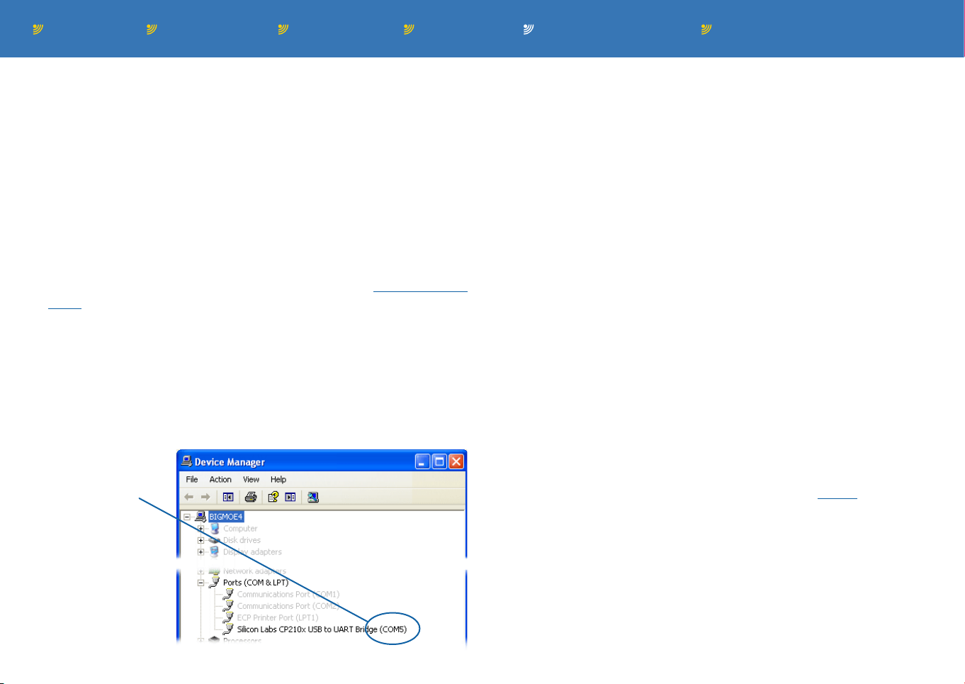
4 Once the installation is complete, view the Device manager (Start
> Control Panel > System > Hardware > Device Manager) and
check which serial port has been
assigned to the
Burnside unit.
To configure the unit as a modem
1 Open the Windows Control Panel (Start > Control Panel) and run
‘Phone and Modems Options’. Change to the Modems tab and
click the Add... button.
2 Ensure that the ‘Don’t detect my modem...’ option is ticked and
then click the Next > button.
3 Under ‘Manufacturer’ select ‘Standard Modem Types’ and then
highlight ‘Standard 19200 bps modem’ and click the Next > button.
4 You will next be asked to choose a serial port. Select the port that
was allocated within the Device Manager during the driver installation (see left). Click the Next > button and the new modem entry
will be created.
5 Select ‘Properties’ for the new modem and click the Configure
button and in the subsequent dialog box, ensure that the Maximum speed is set to ‘115200’.
If you would like to connect to the internet using this modem con-
nection, create a new dialup networking configuration suitable for
your ISP and ensure that the ‘connect using...’ option is set to the
‘Standard 19200 modem’.
See next page for GPRS information
Page 34
Contents Introduction Operation Further informationInstallation Index page 33
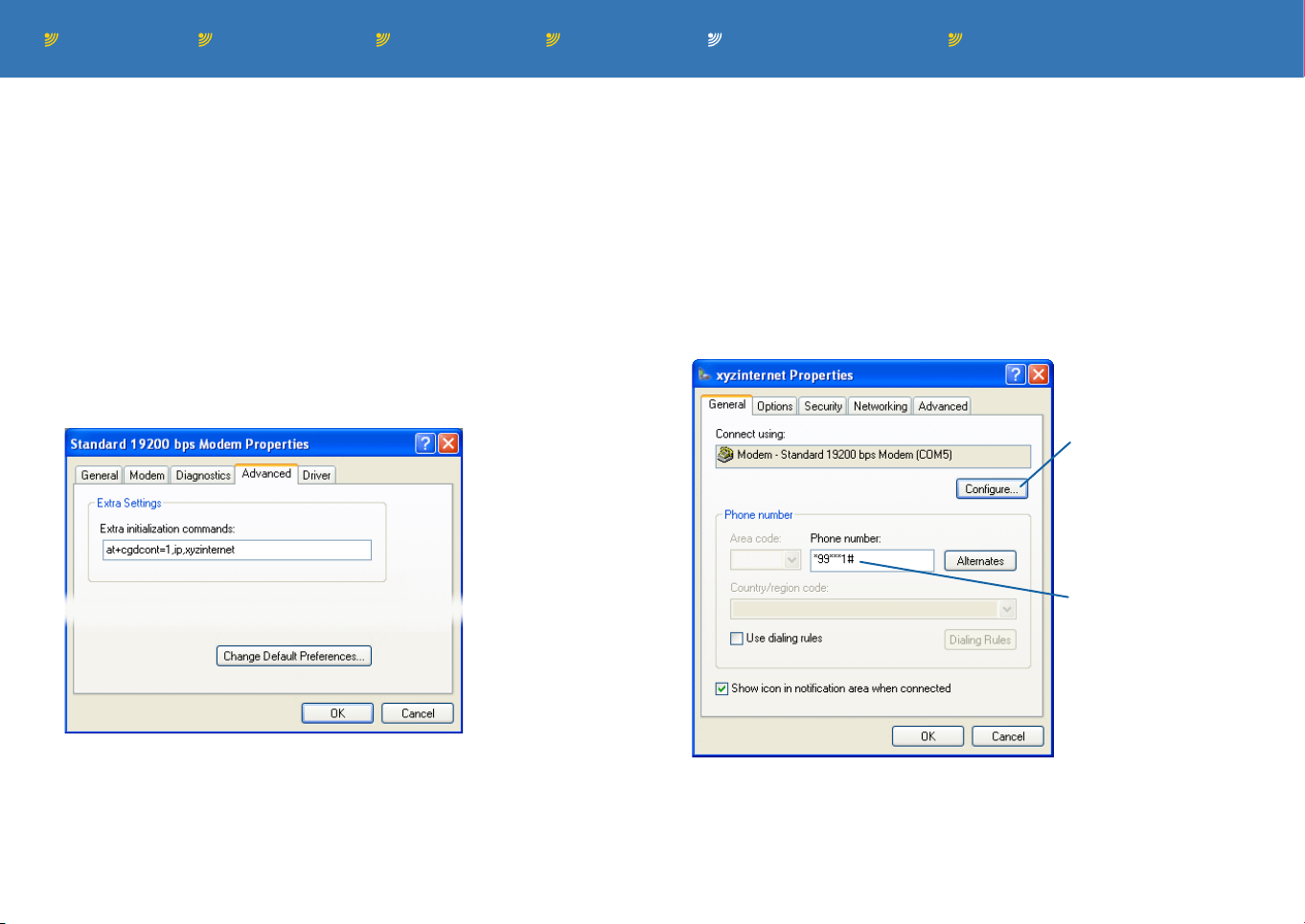
To configure the unit for GPRS
If your SIM supports it, you can connect to the internet using the
higher speed GPRS (General Packet Radio Service) connection.
This will provide data rates typically between 40 to 60 kbps, depending on network congestion, signal quality and other variables.
Contact your service provider for details. To use GPRS, an additional
modem initialisation command is required:
1 Open the Windows Control Panel (Start > Control Panel) and run
‘Phone and Modems Options’. Change to the Modems tab, highlight the entry named ‘Standard 19200 bps modem’ and click the
Properties button.
2 Click on the Advanced tab and edit the ‘Extra initialization com-
mands’ field:
3 Within the Windows Control Panel, run the Network Connections
option. Run the New Connection Wizard and select the following
options as you work through it: ‘Connect to the Internet’ > ‘Set up
my connection manually’ > ‘Connect using a dial-up modem’ >
Choose the new ‘Standard 19200 bps modem’ > Enter a connection name > Enter ‘*99
Internet account information from your ISP > Finish.
4 When the ‘Connect ispname’ dialog is displayed, click the Proper-
ties button to display the following:
1#’ as the phone number > Enter
***
Use this button to make
sure that the ‘Maximum
speed’ is set to 115200.
Also, select ‘Enable
hardware flow control’
Enter at+cgdcont=1,ip,xyzinternet
where xyxinternet is specified by your service provider.
This special command will not interfere with operations when us-
ing the same installation for standard modem and fax.
2 Click OK to save and then click OK to exit the ‘Phone and Modem
Options’ dialog box.
Ensure that the Phone
number is set to
*99***
5 Click the Configure button. Ensure that the ‘Maximum speed’ op-
tion is set to 115200 and also ensure that the ‘Enable hardware
flow control’ option is ticked.
6 Click OK to save and exit.
1#.
Page 35

Contents Introduction Operation Further informationInstallation Index page 34
Appendix 3: Using the input/output channels
The Burnside unit features a link port which allows it to connect to
external devices and either send, or respond to, switched signals.
Combining neatly with the communication features of the unit, the
switched output can be triggered by specially formatted SMS messages, while the inputs can be made to trigger outgoing SMS messages when certain conditions are met.
This section deals with menu configuration aspects of the link port,
for details about physical connections, please see the Connecting to
external devices section.
The link port has two channels:
• Channel 1 can be configured as either an input or output,
• Channel 2 is permanently set as an input.
You can control aspects of this feature using either button presses
(as discussed below) or using remote text commands.
Controlling this feature using phone button presses
Channel 1 (input or output) (0#5410)
• Polarity (0#54110) - Determines how the condition logic (i.e. ‘true’
- action required or ‘false’ - no action required) relates to the
electrical input/output state (i.e. low or high voltage). This option is
also used to enable/disable the channel. Options are ‘Not used’,
‘True=High’ or ‘True=Low’.
• Input or Output selection (0#54120) - Determines whether chan-
nel 1 should operate as an input or an output.
• Text to send (0#54130) - Uses the normal SMS editing method to
create a message and number to call when the input condition is
met.
• Test connection (0#54140) - Displays the current input condition
or allows the output to be toggled to test the connection.
Channel 2 (input only) (0#5420)
• Polarity (0#54210) - Determines how the condition logic (i.e. ‘true’
- action required or ‘false’ - no action required) relates to the electrical input state (i.e. low or high voltage). This option is also used
to enable/disable the channel. Options are ‘Not used’, ‘True=High’
or ‘True=Low’.
• Voltage level (0#54220) - Use this option to select the input volt-
age level that should form the threshold between the ‘true’ (action
required) or ‘false’ (no action required) logic states. This option
offers a range of between 0.5 volts and 4.5 volts in 0.5 steps. The
setting of the channel 2 Polarity option (0#54210) determines the
relationship between the two logic states and the two sides of the
threshold voltage level. Setting the voltage level to 2.5V will effectively provide the same facility as a CMOS digital level detector.
• Text to send (0#54230) - Uses the normal SMS editing method to
create a message and number to call when the input condition is
met.
• Test connection (0#54240) - Displays the current input condition.
Note: The test connection options (0#54140 and 0#54240) refer
to the physical levels of the channels, e.g. low, high, 2.5v, etc.
However, if you use the remote status command (see Appendix 4
- Remote commands), the channel conditions will be reported as
their logical conditions with respect to the polarity that has been
set, i.e. true or false.
Tip: If you need to send an SMS message to two different loca-
tions for a single event, connect both channel inputs together but
store different contact numbers for each channel.
continued
Page 36

Contents Introduction Operation Further informationInstallation Index page 35
Controlling this feature using remote text commands
• Send an SMS message to the unit, formatted as follows:
ppppcc
The first 4 characters
(pppp) must be the
terminal PIN (1234 as
standard, 0#51240 to
change).
Immediately after the terminal PIN (no
space), include the first two characters (cc) of the appropriate command:
• SET Set the channel 1 output to the
true state (high or low - according
to polarity), if channel is enabled.
• CLEAR Clear the channel 1 output
to the false state (high or low - according to polarity), if channel is
enabled.
• ON Activate input monitoring and
lock the terminal.
• OFF Deactivate input monitoring
but the unit will remain locked.
• UNLOCK Deactivate input monitor-
ing if active and unlock the unit.
Note: The two command characters
are not case sensitive.
The unit will normally respond by sending an SMS message back to
the number that sent the command. The response is either the new
status of the unit or an error message if the command is not recognised. If required, you can suppress the reply by placing a fullstop
after the PIN, e.g. 1234.se will set channel 1 without replying.
Note: It is not possible to guarantee that an SMS will be delivered immediately and there are rare occasions when the message will not be
sent at all.
Page 37

Contents Introduction Operation Further informationInstallation Index page 36
Appendix 4: Remote commands
Certain facilities can be controlled remotely by sending an SMS text
message to the Burnside unit from another phone.
To use remote commands
• Send an SMS message to the unit, formatted as follows:
ppppccffffffff
The first four
characters
(pppp) must
be the terminal PIN (1234
as standard,
0#51240 to
change).
After the terminal PIN (no
space), include the first
two characters (cc) of the
appropriate command see Command summary.
Note: The two command
characters are not case
sensitive.
The forward landline
commands allow you
to optionally specify
a forwarding number
(ffffffff).
If no number is given,
the unit will use the
last number specified. If no last number
is stored, it will return
an error message.
When specifying international numbers use
format +nn12345678.
Where nn is the country code.
Command summary
General unit commands
• INIT Restart the unit.
• STATUS Return status information to the caller (see next page).
• WHO Returns a list of up to five landline numbers plus time and
date received.
• LIST Returns a list of up to eleven last received landline numbers.
Call register and tariff counter commands
• ALERT Set the tariff action to alert only.
• TARIFF Returns the status of the tariff counter.
• RESET Reset the tariff counter.
Forward landline commands
• FORWARD Set call forwarding to the number specified and ring
local phone. If no number provided, unit will use the last number
specified. If no number is stored, it will return an error message.
• SILENT As per FORWARD except the local phone will not ring.
• RING As per FORWARD with an announcement to the caller.
• ANNOUN As per FORWARD with announcement but not ring phone.
• CANCEL Cancels call forwarding.
Note: When specifying international numbers in FORWARD, SILENT,
RING or ANNOUN, use the format +nn12345678. Where nn is the
country code.
Landline dial through commands
• IDENTITY Enables dial through, matches Caller ID with phonebook.
• PIN Enables dial through and requires PIN entry.
• NO Disables the dial through feature.
continued
Page 38

Contents Introduction Operation Further informationInstallation Index page 37
Input and output commands
• TRUE Set channel 1 output to the true state (high or low voltage
output, according to polarity setting), if channel is enabled.
• FALSE Set channel 1 output to the false state (high or low voltage
output, according to polarity setting), if channel is enabled.
• ON Activate input monitoring and lock the terminal.
• OFF Deactivate input monitoring but leave the unit locked.
• UNLOCK Deactivate input monitoring if active and unlock the unit.
• LOCK Lock the unit.
Responses to commands
When a command is received, the unit will normally respond by
sending an SMS message back to the number that sent the command. The response is either the new status of the unit or an error
message if the command is not recognised. If required, you can
suppress the reply by placing a fullstop after the PIN, e.g. 1234.Fo
will set forwarding without replying.
Note: Only the first two characters of commands are required and
they are not case sensitive, e.g. 1234sT will have exactly the same
effect as the above full command.
Typical response to a status command:
Monitor: off
Lock: off (the terminal lock condition)
Input1: true (if configured as an output, “input1” is replaced with “Output:”)
Input2: 2.5v-f (the logical condition is also shown, f for false, t for true)
Missed calls: 13
New SMS: 14
SMS space: 11
Signal: -60dBm
Supply: 12.1v
Supply: break (shown if power was lost after monitoring was started)
It is not possible to guarantee that an SMS will be delivered immediately
and there are rare occasions when the message will not be sent at all.
Page 39

Contents Introduction Operation Further informationInstallation Index page 38
Appendix 5: Star hash codes
Star hash codes may be used to control less commonly used facilities and security features. To use, lift the handset and enter the code.
A response will be shown on the display. It is not necessary to hang
up before entering another code.
Basic syntax used in commands
• Register and activate a function
• Activate a function
• Deactivate a function #
• Check status (interrogate)
• Unregister and deactivate ##
Security features
These commands relate to the security access features of the SIM
card and network services. Use the SIM PIN in all of these cases (not
the Terminal PIN).
• Query IMEI
• Change PIN1
• Change PIN2
• Unlock PIN1
• Disable PIN1 lock
• Enable PIN1 lock
• Unblock PIN1
• Unblock PIN2
• Unlock “PS” lock
• Change call barring password
1
1
2
2
3
#06#
*
04oldPin*newPIN*newPin#
**
042*oldPIN2*newPIN2*newPIN2#
**
PIN1#
*8*
870*PIN1#
*
871*PIN1#
*
**05*
052*unblKey*newPIN*newPIN#
**
#0003MasterPhoneCode#
4
*03*
**
*
#
*
unblKey*newPIN*newPIN#
330*oldPw*newPW*newPw#
Phone number presentation
These commands relate to the use of the Caller Line Identity (CLI) or
Caller ID feature supported by the unit.
• Allow network to set CLI condition (default) *801#
• Force sending CLI for all calls
• Force withholding CLI for all calls
• Make a single call and send CLI
• Make a single call and suppress CLI #31#phone number
The following commands must be sent via a USB computer link in
order to receive a valid response code.
• Show CLI presentation state
• Show CLI sending state
• Check presentation state of call *#76# (response: +COLP: 0,n)
• Check presentation state of call *#77# (response: +COLR: 0,n)
(where n is 4 for active and 1 for inactive)
Notes:
1
Some SIM cards will not allow you to disable PIN1 protection.
2
The PUK (Personal UnblocKing code) is provided by your serv-
ice provider. See SIM security features.
3
The PS (Phone to SIM) lock is an optional feature which ensures
that the unit may only be used with a single SIM card. The Master Phone Code is issued by Burnside Telecom once the IMEI
number (printed on the underside of the terminal) is declared.
Please contact Burnside Telecom for more details about this
optional feature.
4
Confirm the old call barring password with your network service
provider.
*
*
802#
*
803#
*
31#phone number
*
#30# (response: +CLIP: 0,n)
#31# (response: +CLIR: 0,n)
Page 40

Contents Introduction Operation Further informationInstallation Index page 39
[ACTION] <PHONE NUMBER> <SERVICE> #
Appendix 6: Advanced configuration codes
The advanced configuration codes may be entered using the telephone
handset and also, when using a USB data connection, by using the dialling sequence “ATD” followed by the appropriate configuration code.
When using the data connection, it is also possible to interrogate the
status of certain network settings, using the
Call forwarding
Call forwarding is a network service which allows incoming calls to
be diverted to an alternative number (such as a voicemail box) when
certain criteria are met. In concert with your service provider, the
terminal allows you to control various aspects of the call forwarding
service. The various forwarding criteria are not mutually exclusive
and can be used in combination to divert different types of calls to
separate numbers. Commands are composed as follows:
[ACTION] criteria:
Forward unconditionally 21
Forward when busy 67
Forward when no reply 61
Forward when signal lost 62
Forward all calls 002
Forward all conditional types 004
<PHONE NUMBER>
to which calls that
meet the criteria
should be forwarded
# command prefix.
*
Command
suffix
Call forwarding examples
• To register a new number and activate call forwarding when busy
(to the phone number 01234 567890):
• To deactivate call forwarding when busy: #67
01234567890*#
**67*
*
• To reactivate call forwarding when busy to 01234 567890 again:
*67*
Command prefixes:
Activate
Register and activate
Deactivate #
Unregister and deactivate ##
Check status (interrogate)¹ *#
¹ Interrogation is only possible
via a data connection.
<SERVICE> types:
Voice only 11
*
Fax only 13
**
SMS only 16
SMS+FAX 12
Voice+FAX 19
Voice+SMS+FAX 10
Data circuit async. 25
Data circuit sync. 24
PAD 27
Packet 26
Data circuit async+PAD 21
Data circuit sync.+packet 22
Data circuit asyn.+sync.+PAD 20
All services (omit code)
The service type allows you to optionally
specify one or more particular types of
incoming call to forward.
Page 41

Contents Introduction Operation Further informationInstallation Index page 40
[ACTION] [PASSWORD] <SERVICE> #
Call barring
Call barring is a network service which allows incoming and/or
outgoing calls that meet certain criteria to be barred from being
received or made. In concert with your service provider, the terminal
allows you to control various aspects of the call barring service. The
various barring criteria are not mutually exclusive and can be used
in combination to produce a tighter set of barring regulations. Commands are composed as follows:
[ACTION] criteria:
Bar all outgoing calls 33
Bar all outgoing international calls 331
Bar all outgoing international calls except to home country 332
Bar all incoming calls 35
Bar all incoming calls outside of home country 351
Note: The PASSWORD is
initially configured by the
network service provider
and is typically 0000
or 1111. This can be
changed - see ‘Security
features’ on page 27
Command
suffix
Deactivating collective barring settings
For all of the [ACTION] criteria shown above, it is possible to deactivate them individually using the # command type and their respective criteria codes. However, it is also possible to deactivate the
following three barring groups collectively:
• Deactivate all barring #330
• Deactivate all outgoing barring #333
• Deactivate all incoming barring #353
[PASSWORD]*<SERVICE>#
*
[PASSWORD]*<SERVICE>#
*
[PASSWORD]*<SERVICE>#
*
Call barring examples
• To bar all international voice calls (where the password is 0000):
#331*0000*11#
• To deactivate all call barring (where the password is 1111):
#330*1111#
Command prefixes:
Activate
Deactivate #
Check status (interrogate)¹ *#
¹ Interrogation is only possible
via a data connection.
<SERVICE> types:
Voice only 11
*
Fax only 13
SMS only 16
SMS+FAX 12
Voice+FAX 19
Voice+SMS+FAX 10
Data circuit async. 25
Data circuit sync. 24
PAD 27
Packet 26
Data circuit async+PAD 21
Data circuit sync.+packet 22
Data circuit asyn.+sync.+PAD 20
All services (omit code)
The service type allows you to optionally
specify the services to be barred.
Page 42

Contents Introduction Operation Further informationInstallation Index page 41
43 <SERVICE> #
Call waiting
Call waiting is a network service that, when enabled, signals an
incoming call when a call is already in progress and additionally allows the first call to be held while the second is answered. In concert
with your service provider, the terminal allows you to control various
aspects of the call waiting service. Commands are composed as
follows:
Command
suffix
Command prefixes:
Activate
Deactivate #
Check status (interrogate)¹ *#
¹ Interrogation is only possible
via a data connection.
<SERVICE> types:
Voice only 11
*
Fax only 13
SMS only 16
SMS+FAX 12
Voice+FAX 19
Voice+SMS+FAX 10
Data circuit async. 25
Data circuit sync. 24
PAD 27
Packet 26
Data circuit async+PAD 21
Data circuit sync.+packet 22
Data circuit asyn.+sync.+PAD 20
All services (omit code)
Call waiting examples
• To activate call waiting for all types of call:
• To deactivate call waiting for all types of call: #43#
43#
*
The service type allows you to optionally
specify one or more particular types of
incoming call which will be permitted to
interrupt an existing call.
Page 43

Contents Introduction Operation Further informationInstallation Index page 42
Appendix 7: SMS key characters
The unit is designed to support basic text messaging. If the unit is
sent picture messages, business cards or other special messages,
these may be displayed as meaningless message text. If this
occurs, delete the message.
The terminal is capable of displaying the full range of GSM
characters.
When a character is received that is not supported, it is replaced
with ¿ or a block character.
Characters assigned to each key
1 .1?!,@_&:”’¿
(no case change)
2 ABC2ДЕаЖЯз
abc2деажЯз
3 DEF3ÉèΦ
def3éèΦ
4 GHI4Γì
ghi4Γì
5 JKL5Λ
jkl5Λ
Note: The character set is subject to change.
6 MNO6ÑÖØòΏ
mno6ñöøòΏ
7 PQRS7ΠβΣ
pqrs7ΠβΣ
8 TUV8ÜÙ
tuv8üù
9 WXYZ9ΞΨ
wxyz9ΞΨ
0 0()%£$€¥#+-
(the first character is a space)
(no case change)
To change between
upper and lower case
Press and hold any
character key (2 to 9)
Page 44

Contents Introduction Operation Further informationInstallation Index page 43
Appendix 8: SIM security features
When entering PINs, there are no editing functions. Take care to
correctly enter the PIN. The digits entered are displayed with the
* character for security purposes, so 1234 would be displayed as
****. The SIM PIN mechanism is designed to provide a high level of
protection. Three attempts are permitted for normal PIN entry, after
which the unblocking code will be required (PUK). This is protected
by several levels of time prevention to avoid repeated guessed attempts. A total of 10 attempts are allowed before the SIM is rendered
completely unusable.
Time to wait before next PUK input is allowed
• 1st failed attempt, no time to wait
• 2nd failed attempt, 4 seconds
• From 3rd failed attempt, 256 seconds each time
The SIM pin can be between 4 and 8 digits. The PUK is always 8
digits and can be obtained from your service provider.
The Burnside unit’s Terminal PIN is fixed to 4 digits and the security
measures are simpler. After 3 failed attempts, a delay of 1 minute is
applied before accepting another attempt, but importantly, the code
stored for auto SIM unlock is erased. If the unit is powered off and on
again this delay is cleared.
The most important and financially hazardous situation is to leave
the SIM unlocked. If the terminal PIN is lost, contact:
[email protected] for a release code to restore the
default.
Emergency calls only
If the SIM is locked or there is not even a SIM in the terminal, it is still
possible to make emergency calls by dialling the 112 or 999 (in the
UK) emergency number.
Auto unlock precaution
The SIM auto unlock facility works by remembering the last successful PIN that was used. If the auto-unlock facility is then enabled, it will
unlock the SIM. However, if the SIM is changed for another SIM, the
auto unlock facility is cleared.
IMEI code (International Mobile station Equipment Identity)
This is a unique 15 digit number that we recommend you write down
in the front of this manual in the place provided. To view this number
dial *#06# or look on the label on the underside of the unit. This
number can be used by network operators to permanently block the
use of the terminal in the event of theft. You may also be asked for
this code when requesting support.
Page 45

Contents Introduction Operation Further informationInstallation Index page 44
Important safety information
Operating environment
Make sure that no special regulation is in force that imposes restrictions on the use of mobile telephones. Restrictions to mobile telephones would also apply to this phone.
Electronic devices
Most modern electronic equipment is shielded from radio frequency
(RF) signals. However, certain electronic equipment may not be
shielded against the RF signals from your phone.
Pacemakers
Pacemaker manufacturers recommend that a minimum separation
of 20 cm (6 inches) be maintained between a hand-held wireless
phone and a pacemaker The same restriction should apply to the
external antenna of the phone. If you have any reason to suspect
that interference is taking place, switch off the phone immediately.
Hearing aids
The phone radio signals may interfere with some hearing aids. In
such event move the antenna as far away as practical or consult
your hearing aid supplier.
Other medical devices
Operation of any radio transmitting equipment, including the phone,
may interfere with the function of inadequately protected medical devices. Consult a physician or the manufacturer of the medical device
to determine if they are adequately shielded from external RF energy
or if you have any questions.
Switch off your phone in health care facilities when any regulations
posted in these areas instruct you to do so. Hospitals or health care
facilities may be using equipment that could be sensitive to external
RF energy.
Vehicles
RF signals may affect improperly installed or inadequately shielded
electronic systems in motor vehicles (e.g. electronic fuel injection
systems, electronic anti-skid (anti-lock) braking systems, electronic
speed control systems, airbag systems).
Check with the manufacturer or its representative regarding your
vehicle. You should also consult the manufacturer of any equipment
that has been added to your vehicle.
Potentially explosive atmospheres
Do not install the phone or site the antenna in any area with a potentially explosive atmosphere and obey all signs and instructions. Areas with a potentially explosive atmosphere are often but not always
clearly marked. They include chemical transfer or storage facilities;
vehicles using liquefied petroleum gas (such as propane or butane):
areas where the air contains chemicals or particles, such as grain,
dust or metal powders.
Emergency calls
IMPORTANT: The phone, like any wireless phone, operates using
radio signals, wireless and landline networks, as well as user-programmed functions, which cannot guarantee connection in all conditions. Therefore, you should never rely solely upon any wireless
phone for essential communications (e.g. medical emergencies).
Remember, to make or receive any calls the phone must be
switched on and in a service area with adequate cellular signal
strength. Emergency calls may not be possible on all wireless phone
networks or when certain network services and/or phone features
are in use. Check with local cellular service providers. Emergency
calls may be made even when a SIM card is not installed (subject to
network availability) using the 112 dialling code.
Page 46

Contents Introduction Operation Further informationInstallation Index page 45
Index
A
Antenna
connecting 5
Asterisk PBX
disconnect clear time 29
B
Burnside Telecom
25
C
Cable adapter 4
Call barring
codes 40
configuration 40
Call diverting
mobile 23
Caller ID
configuration 38
Call forwarding
codes 39
configuration 39
Call handling
features 18
Call register
erase list 15
GPRS log 15
viewing 15
Calls
abort fax or data 22
in-call dial 24
international 9
making & receiving 9
Calls (cont.)
multiparty 24
network features 23
speed dial 9
Call time
restrict 17
Call waiting
codes 41
configuration 41
mobile 23
Character and
numeral editing 13
Clock
setting 8
Computer
connecting 6
Configuration codes
advanced 39
Contact
Burnside Telecom 25
D
Data connection 32
Date
setting 8
disconnect clear time 29
E
External devices
connecting 7
F
Forward land line 2, 20
G
GPRS
call register log 15
I
IMEI code 43
In-call dial 24
input/output channels 34
International calls 9
J
Jack plug
wiring 7
K
K-Break 29
Kewlstart
disconnect clear time 29
L
Land line
connecting 5
forwarding 20
land line connection
manual selection 18
Land line dial through 2, 19
M
Manual routing
of landline calls 18
Menu options 26
O
Outgoing call routing 2,
18, 30
P
Phonebook 10
add entry 10
call entry 10
edit entry 11
erase entry 12
memory status 11
Positioning the unit 3
Power adapter
connecting 6
PUK code
entry 43
R
Remote commands 36
Restrict call time 17
Routing manually
of landline calls 18
S
Safety information 44
Security features 43
SIM card
inserting 4
SMS
key characters 42
text messaging 13
Special functions 30
Speed dial
call 10
speed dial calls 9
Star hash codes 38
T
Tariff timer
functions 16
reset 17
Telephone
connecting 4
Text messaging 13
read message 14
send message 13
settings 14
view outbox 14
Time
setting 8
Transfer
landline callls 18
U
Unblocking code
entry 43
Documentation by:
ww w.ctxd. co m
October 2009
Rev 1.0d
Page 47

BURNSIDE
www.burnsidetelecom.com
Burnside Telecom Limited
Burnside House, Isington, Alton
GU34 4PP, United Kingdom
Tel: +44 (0)8700 762766
Fax: +44 (0)1420 520029
Email: [email protected]
 Loading...