

Burnham Water boiler, ALP080, ALP105, ALP150, ALP210 Installation, Operating And Service Instructions
...
DNAGNITAREPO,NOITALLATSNI
ROFSNOITCURTSNIECIVRES
™ENIPLA
YCNEICIFFEHGIHGNISNEDNOC
TNEVTCERID
RELIOBRETAWTOHDERIF-SAG
9700609
As an ENERGY STAR
ENERGY STAR
WaRning: Improper installation, adjustment, alteration, service or maintenance can cause property damage,
injury, or loss of life. For assistance or additional information, consult a qualied installer, service agency or the
gas supplier. This boiler requires a special venting system. Read these instructions carefully before installing.
®
®
Partner, Burnham by U.S. Boiler Company has determined that the Alpine™ Series meets the
guidelines for energy efciency established by the United States Environmental Protection Agency (EPA).
101602-01R9-9/10
Price - $5.00
IMPORTANT INFORMATION - READ CAREFULLY
NOTE: The equipment shall be installed in accordance with those installation regulations enforced in the area where the
installation is to be made. These regulations shall be carefully followed in all cases. Authorities having jurisdiction
shall be consulted before installations are made.
All wiring on boilers installed in the USA shall be made in accordance with the National Electrical Code and/or local regulations.
All wiring on boilers installed in Canada shall be made in accordance with the Canadian Electrical Code and/or local regulations.
The City of New York requires a Licensed Master Plumber supervise the installation of this product.
The Massachusetts Board of Plumbers and Gas Fitters has approved the Alpine™ Series boiler. See the Massachusetts Board of
Plumbers and Gas Fitters website, http://license.reg.state.ma.us/pubLic/pl_products/pb_pre_form.asp for the latest Approval
Code or ask your local Sales Representative.
The Commonwealth of Massachusetts requires this product to be installed by a Licensed Plumber or Gas Fitter.
The following terms are used throughout this manual to bring attention to the presence of hazards of various risk levels,
or to important information concerning product life.
DangER
indicates an imminently hazardous situation
which, if not avoided, will result in death, serious
injury or substantial property damage.
WaRning
indicates a potentially hazardous situation which,
if not avoided, could result in death, serious injury
or substantial property damage.
indicates a potentially hazardous situation which,
if not avoided, may result in moderate or minor
injury or property damage.
indicates special instructions on installation,
operation, or maintenance which are important
but not related to personal injury hazards.
CaUTiOn
nOTiCE
DangER
DO NOT store or use gasoline or other ammable vapors or liquids in the vicinity of this or any other
appliance.
if you smell gas vapors, nO nOT try to operate any appliance - DO nOT touch any electrical switch or use
any phone in the building. immediately, call the gas supplier from a remotely located phone. Follow the gas
supplier’s instructions or if the supplier is unavailable, contact the re department.
2

Special Installation Requirements for Massachusetts
A. For all sidewall horizontally vented gas fueled equipment installed in every dwelling, building or structure used in whole or
in part for residential purposes and where the sidewall exhaust vent termination is less than seven (7) feet above grade, the
following requirements shall be satised:
1. If there is no carbon monoxide detector with an alarm already installed in compliance with the most current edition of
NFPA 720, NFPA 70 and the Massachusetts State Building Code in the residential unit served by the sidewall horizontally
vented gas fueled equipment, a battery operated carbon monoxide detector with an alarm shall be installed in compliance
with the most current edition of NFPA 720, NFPA 70 and the Massachusetts State Building Code.
2.
In addition to the above requirements, if there is not one already present, a carbon monoxide detector with an alarm
and a battery back-up shall be installed and located in accordance with the installation requirements supplied with the
detector on the oor level where the gas equipment is installed. The carbon monoxide detector with an alarm shall
comply with 527 CMR, ANSI/UL 2034 Standards or CSA 6.19 and the most current edition of NFPA 720. In the event
that the requirements of this subdivision can not be met at the time of the completion of the installation of the equipment,
the installer shall have a period of thirty (30) days to comply with this requirement; provided, however, that during
said thirty (30) day period, a battery operated carbon monoxide detector with an alarm shall be installed in compliance
with the most current edition of NFPA 720, NFPA 70 and the Massachusetts State Building Code. In the event that the
sidewall horizontally vented gas fueled equipment is installed in a crawl space or an attic, the carbon monoxide detector
may be installed on the next adjacent habitable oor level. Such detector may be a battery operated carbon monoxide
detector with an alarm and shall be installed in compliance with the most current edition of NFPA 720, NFPA 70 and the
Massachusetts State Building Code.
3. A metal or plastic identication plate shall be permanently mounted to the exterior of the building at a minimum height
of eight (8) feet above grade directly in line with the exhaust vent terminal for the horizontally vented gas fueled
heating appliance or equipment. The sign shall read, in print size no less than one-half (1/2) inch in size, “GAS VENT
DIRECTLY BELOW. KEEP CLEAR OF ALL OBSTRUCTIONS”.
4. A nal inspection by the state or local gas inspector of the sidewall horizontally vented equipment shall not be performed
until proof is provided that the state or local electrical inspector having jurisdiction has granted a permit for installation of
carbon monoxide detectors and alarms as required above.
B. EXEMPTIONS: The following equipment is exempt from 248 CMR 5.08(2)(a) 1 through 4:
1. The equipment listed in Chapter 10 entitled “Equipment Not Required To Be Vented” in the most current edition of NFPA
54 as adopted by the Board; and
2. Product Approved sidewall horizontally vented gas fueled equipment installed in a room or structure separate from the
dwelling, building or structure used in whole or in part for residential purposes.
When the manufacturer of Product Approved sidewall horizontally vented gas equipment provides a venting system design
C.
or venting system components with the equipment, the instructions for installation of the equipment and the venting system
shall include:
1.
A complete parts list for the venting system design or venting system; and
2. Detailed instructions for the installation of the venting system design or the venting system components.
D. When the manufacturer of a Product Approved sidewall horizontally vented gas fueled equipment does not provide the parts
for venting ue gases, but identies “special venting systems”, the following shall be satised:
1. The referenced “special venting system” instructions shall be included with the appliance or equipment installation
instructions; and
2. The “special venting systems” shall be Product Approved by the Board, and the instructions for that system shall include a
parts list and detailed installation instructions.
E. A copy of all installation instructions for all Product Approved sidewall horizontally vented gas fueled equipment, all venting
instructions, all parts lists for venting instructions, and/or all venting design instructions shall remain with the appliance or
equipment at the completion of the installation.
3
WaRning
This boiler requires regular maintenance and service to operate safely. Follow the instructions contained
in this manual.
improper installation, adjustment, alteration, service or maintenance can cause property damage, personal
injury or loss of life. Read and understand the entire manual before attempting installation, start-up
operation,
knowledgeable installer or service agency
This boiler must be properly vented.
This boiler needs fresh air for safe operation and must be installed so there are provisions for adequate
combustion and ventilation air.
The interior of the venting system must be inspected and cleaned before the start of the heating season
and
should be inspected periodically throughout the heating season for any obstructions. a clean and
unobstructed venting system is necessary to allow noxious fumes that could cause injury or loss of life
to vent safely and will contribute toward maintaining the boiler’s efciency.
installation is not complete unless a pressure relief valve is installed into the tapping located on left side
of appliance. - See the Water Piping and Trim Section of this manual for details.
This boiler is supplied with safety devices which may cause the boiler to shut down and not re-start
without
unattended in cold weather; or appropriate safeguards and alarms should be installed on the heating
system to prevent damage if the boiler is inoperative.
or service. installation and service must be performed only by an experienced, skilled, and
service. if damage due to frozen pipes is a possibility, the heating system should not be left
This boiler contains very hot water under high pressure. Do not unscrew any pipe ttings nor attempt
to disconnect any components of this boiler without positively assuring the water is cool and has no
pressure. Always wear protective clothing and equipment when installing, starting up or servicing this
boiler to prevent scald injuries. Do not rely on the pressure and temperature gauges to determine the
temperature and pressure of the boiler. This boiler contains components which become very hot when
the boiler is operating. Do not touch any components unless they are cool.
Boiler materials of construction, products of combustion and the fuel contain alumina, silica, heavy metals,
carbon monoxide, nitrogen oxides, aldehydes and/or other toxic or harmful substances which can cause
death or serious injury and which are known to the state of California to cause cancer, birth defects and
other reproductive harm. Always use proper safety clothing, respirators and equipment when servicing
or working nearby the appliance.
Failure to follow all instructions in the proper order can cause personal injury or death. Read all instruc-
tions, including all those contained in component manufacturers manuals which are provided with the
boiler before installing, starting up, operating, maintaining or servicing.
a
ll cover plates, enclosures and guards must be in place at all times.
nOTiCE
This boiler has a limited warranty, a copy of which is printed on the back of this manual. it is the responsibility
of the installing contractor to see that all controls are correctly installed and are operating properly when the
installation is complete.
4
TABLE OF CONTENTS
I. Product Description, Specications and Dimensional Data...................... 6
II. Pre-Installation & Boiler Mounting ............................................................ 13
III. Unpacking Boiler........................................................................................ 17
IV. Venting...................................................................................................... 18
General Guidelines............................................................................... 18
A.
CPVC/PVC Venting.............................................................................. 21
B.
Stainless Steel Venting........................................................................ 29
C.
Concentric Polypropylene.................................................................... 31
D.
Removing the Existing Boiler............................................................... 38
E.
V. Condensate Disposal................................................................................. 39
VI. Water Piping and Trim............................................................................... 41
VII. Gas Piping ................................................................................................ 50
VIII. Electrical ................................................................................................... 54
IX. Boiler Stacking ......................................................................................... 61
X. Modular Installation................................................................................... 63
General Guidelines.............................................................................. 63
A.
Venting................................................................................................ 63
B.
Water Piping and Trim......................................................................... 66
C.
D. Gas Piping........................................................................................... 66
Electrical.............................................................................................. 76
E.
. External Modular Boiler Controls......................................................... 76
F
Modular Boiler Operating Information.................................................. 77
G.
Major Features............................................................................... 77
1.
Operating Modes........................................................................... 79
2.
Required Equipment and Setup..................................................... 81
3.
Adjusting Parameters.................................................................... 83
4.
XI. System Start-up ...................................................................................... 86
XII. Operation ................................................................................................. 92
Major Features..................................................................................... 92
A.
Operating Mode................................................................................... 96
B.
1. Home Screen................................................................................ 96
Boiler Status Screen...................................................................... 97
2.
Controls Start-up Checklist.................................................................. 98
C.
User Interface...................................................................................... 99
D.
Using The Display.......................................................................... 99
1.
Selecting View Mode Options........................................................ 99
2.
Help Screens................................................................................. 100
3.
Entering Adjust Mode.................................................................... 101
4.
Adjusting Parameters........................................................................... 102
E.
XIII. Service and Maintenance ......................................................................... 110
XIV. Troubleshooting........................................................................................ 114
XV. Repair Parts ............................................................................................. 117
Appendix B - Figures................................................................................ 126
Appendix C - Tables.................................................................................. 129
Warranty...........................................................................................Back Page
5
I. Product Description, Specications and Dimensional Data
Alpine™ Series boilers are condensing high efciency
gas-red direct vent hot water boilers designed for use
in forced hot water space or space heating with indirect
domestic hot water heating systems, where supply water
temperature does not exceed 210°F. These boilers have
special coil type stainless steel heat exchangers, constructed,
tested and stamped per Section IV ‘Heating Boilers’ of
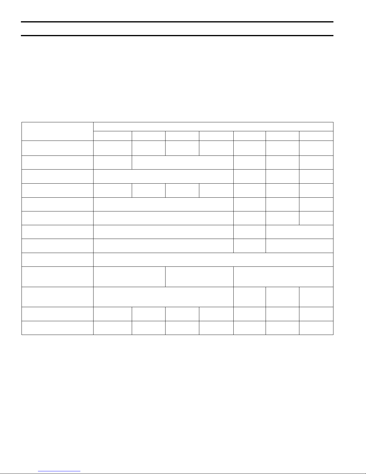
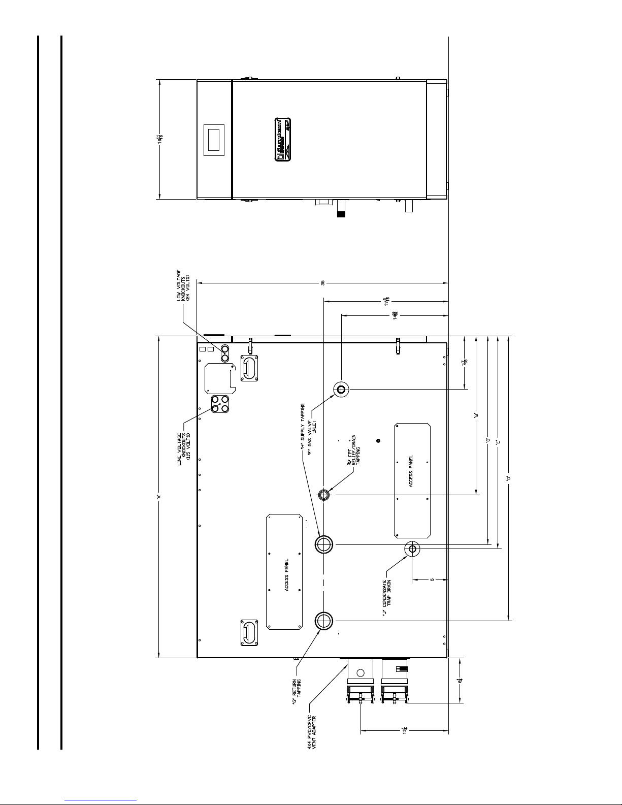
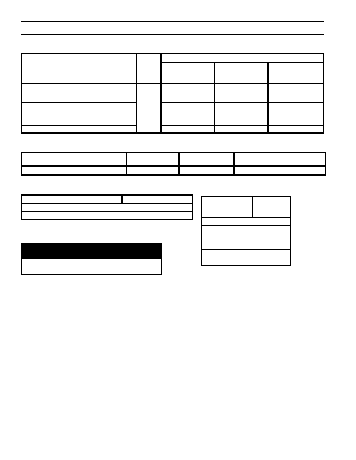
Table 1: Dimensional Data (See Figures 1a, 1B, 1C & 1D)
Dimension
A - Inch
(mm)
B - Inch
(mm)
C - Inch
(mm)
D - Inch
(mm)
E - Inch
(mm)
Gas Inlet F
(FPT)
Return G
(FPT)
Supply H
(FPT)
Condensate Drain J *
Boiler Two-Pipe
CPVC/PVC Vent Connector
(Figs. 1A, 1C, 1D) - Inch
Boiler
CPVC Vent Connector/Pipe
(Fig. 1B) - Inch
Boiler Inlet Air Connector
(Fig. 1B) - Inch
Approx. Shipping Weight
(LBS)
ALP080
12-9/16
(1)
ALP105
(320)
5-5/8
(142)
9-5/16
(237)
* Factory Provided Socket End Compression Pipe Joining Clamp
3 x 3 3 x 4 4 x 4
3” 3” 4” 4” N/A N/A N/A
137 155 182 206 256 304 350
(1)
ALP150
14
(356)
10-3/4
(273)
19-11/16
(500)
5-13/16
(147)
7-5/16
(186)
16-7/16
(417)
5-15/16
(151)
1/2” 3/4” 3/4” 3/4”
1” 1-1/4” 1-1/2”
1” 1-1/4” 1-1/2”
for 3/4” Schedule 40 PVC Pipe
3” N/A N/A N/A
ASME Boiler and Pressure Vessel Code, which provide a
maximum heat transfer and simultaneous protection against
ue gas product corrosion. These boilers are not designed
for use in gravity hot water space heating systems or
systems containing signicant amount of dissolved oxygen
(swimming pool water heating, direct domestic hot water
heating, etc.).
Boiler Model
(1)
ALP210
23-15/16
(608)
17-1/8
(435)
(1)
ALP285
21-13/16
(554)
7-5/16
(185)
14-1/8
(358)
18
(456)
12-1/4
(312)
(2)
ALP399
28-7/8
(734)
6-3/16
(157)
13-1/16
(332)
23-3/4
(602)
15-13/16
(402)
(2)
ALP500
44-7/8
(1140)
22-1/8
(562)
29
(737)
39-11/16
(1008)
29-3/8
(752)
(2)
nOTES:
(1)
- These boiler models available as either Floor mounted (sufx F) or, Wall mounted (sufx W).
(2)
- These boiler models available as Floor mounted (sufx F) only.
6
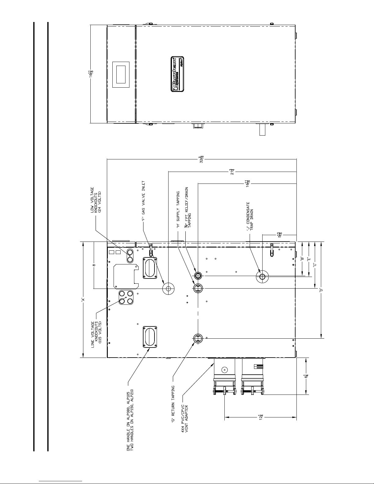
I. Product Description, Specications and Dimensional Data (continued)
Figure 1a: alpine™ - Models aLP080 thru aLP210 (Floor Mounted)
7
I. Product Description, Specications and Dimensional Data (continued)
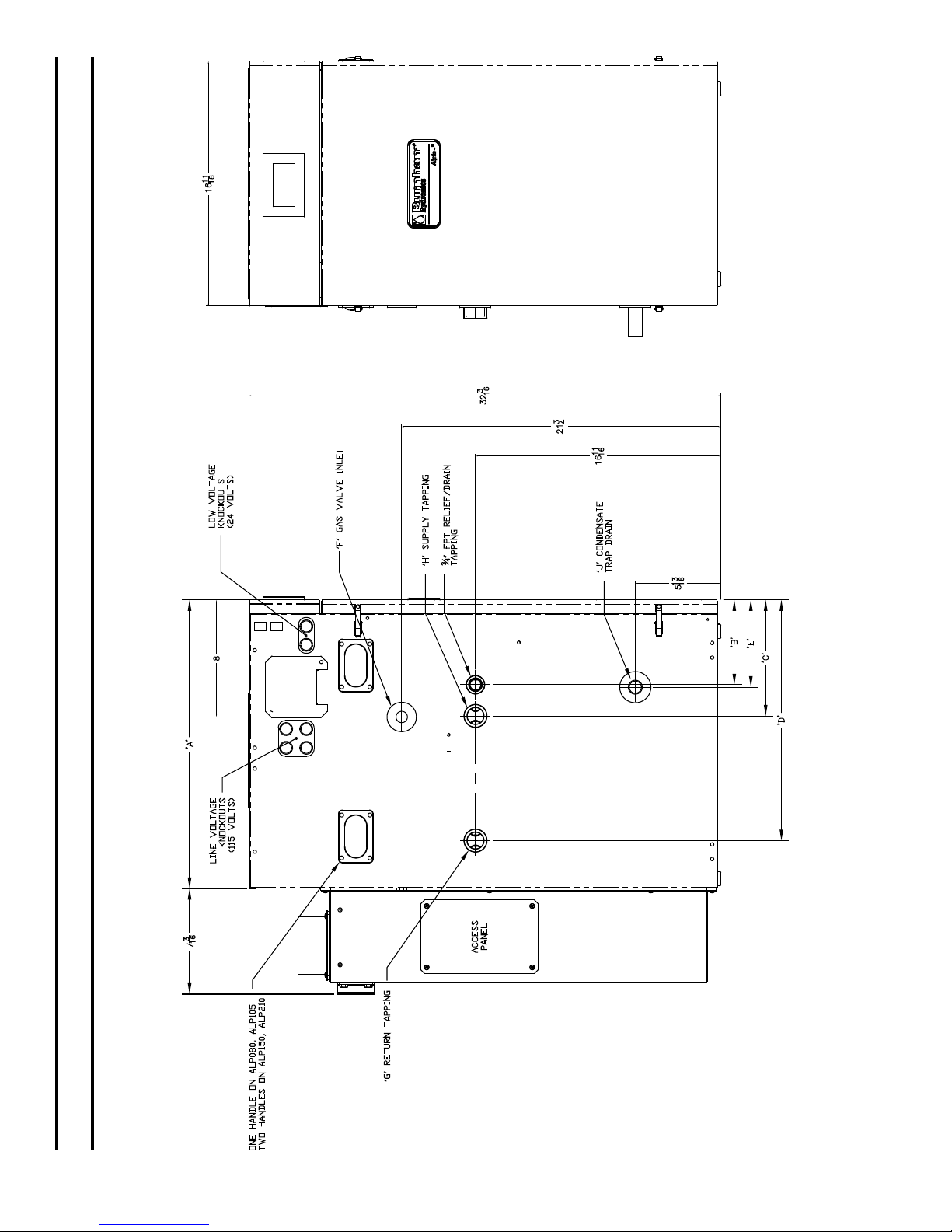
8
Figure 1B: alpine™ - Models aLP080 thru aLP210 (Wall Mounted)
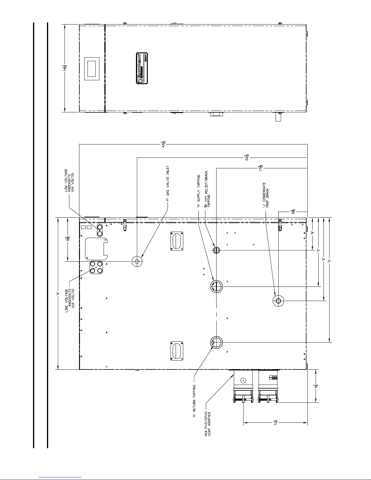
I. Product Description, Specications and Dimensional Data (continued)
Figure 1C: alpine™ - Models aLP285 thru aLP399 (Floor Mounted Only)
9
I. Product Description, Specications and Dimensional Data (continued)
10
Figure 1D: alpine™ - Model aLP500 (Floor Mounted Only)
I. Product Description, Specications and Dimensional Data (continued)
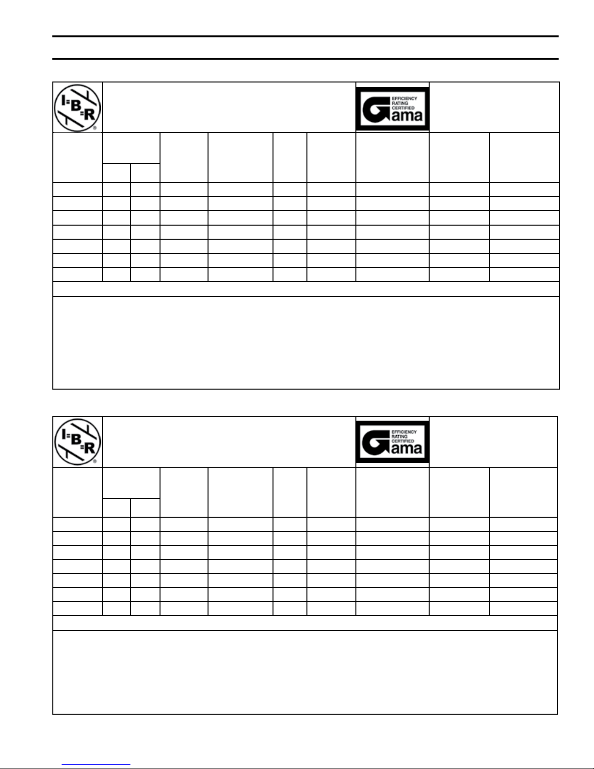
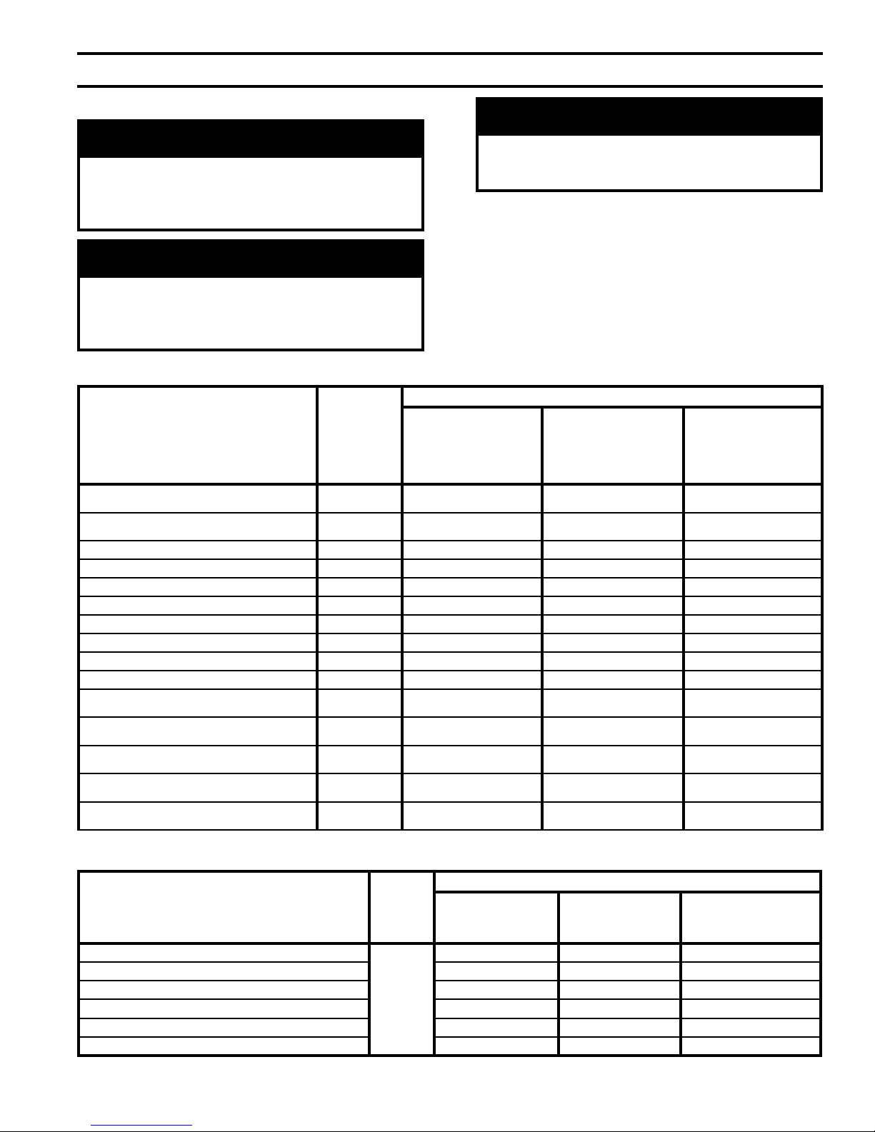
Table 2a: Rating Data - Models aLP080 thru aLP500 (0 to 2000 Feet Elevation above Sea Level)
alpine Series gas-Fired Boilers
* Model
Number
ALP080 16 80 73 63 95 0.6 7.3
ALP105 21 105 96 83 95 0.7 9.1
ALP150 30 150 138 120 95 1.3 16.4
ALP210 42 210 194 169 95 1.7 21.8
ALP285 57 285 265 230 95 2.4 29.1
ALP399 80 399 377 328 94 95 3.4 41.8
ALP500 100 500 475 413 95 95 4.2 50.8
(MBH)
Min. Max.
** Output
(MBH)
Input
Net I=B=R
Ratings
Water (MBH)
AFUE
%
Thermal
Efciency
(%)
Combustion
Efciency (%)
Boiler Water
Volume
(Gal.)
Heat Transfer
Area
(Sq. Ft.)
* Add Sufx “F” for Floor mounted Models or Sufx “W” for Wall mounted Models.
notes: ** DOE Heating Capacity (ALP080 thru ALP285); Gross Output (ALP399 thru ALP500)
Maximum Working Pressure, Water - 30 PSI Shipped from Factory (std.); 50 PSI, 80 PSI and 100 PSI - Optional (ALP080 thru ALP285)
Maximum Working Pressure, Water - 50 PSI Shipped from Factory (std.); 80 PSI and 100 PSI - Optional (ALP399 thru ALP500)
Maximum Allowable Temperature, Water - 210°F, Maximum Firing Rate Target Setpoint is 190°F, Automatic Reset High Limit Setpoint
is 200°F and Manual Reset High Limit Setpoint is 210°F.
Boilers are factory shipped as Natural Gas builds and have to be eld adjusted for LP gas application. Refer to ‘System Start-
Up Section of this manual for detailed procedure.
Ratings shown are for installations at sea level and elevations up to 2000 Feet. For elevations above 2000 Feet, ratings should be
reduced at the rate of four percent (4%) for each 1000 Feet above sea level.
Table 2B: Rating Data - Models aLP080 thru aLP500 (2001 to 7000 Feet Elevation above Sea Level)
alpine Series gas-Fired Boilers
Model
Number *
ALP080 27 80 73 63 95 0.6 7.3
ALP105 35 105 96 83 95 0.7 9.1
ALP150 50 150 138 120 95 1.3 16.4
ALP210 70 210 194 169 95 1.7 21.8
ALP285 57 285 265 230 95 2.4 29.1
ALP399 80 399 377 328 94 95 3.4 41.8
ALP500 100 500 475 413 95 95 4.2 50.8
(MBH)
Min. Max.
** Output
(MBH)
* Add Sufx “F” for Floor mounted Models or Sufx “W” for Wall mounted Models.
notes: ** DOE Heating Capacity (ALP080 thru ALP285); Gross Output (ALP399 thru ALP500)
Maximum Working Pressure, Water - 30 PSI Shipped from Factory (std.); 50 PSI, 80 PSI and 100 PSI - Optional
Maximum Working Pressure, Water - 50 PSI Shipped from Factory (std.); 80 PSI and 100 PSI - Optional (ALP399 thru ALP500)
Maximum Allowable Temperature, Water - 210°F, Maximum Firing Rate Target Setpoint is 190°F, Automatic Reset High Limit Setpoint
is 200°F and Manual Reset High Limit Setpoint is 210°F.
Boilers are factory shipped as Natural Gas builds and have to be eld adjusted for LP gas application. Refer to ‘System Start-
Up” Section of this manual for detailed procedure.
For elevations above 2000 Feet, ratings should be reduced at the rate of four percent (4%) for each 1000 Feet above sea level.
Input
Net I=B=R
Ratings
Water (MBH)
AFUE
%
Thermal
Efciency
(%)
Combustion
Efciency (%)
Boiler Water
Volume
(Gal.)
Heat Transfer
Area (Sq. Ft.)
11
I. Product Description, Specications and Dimensional Data (continued)
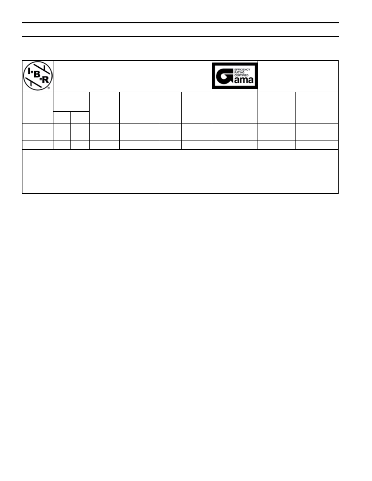
Table 2C: Rating Data - Models aLP150 thru aLP285 (7001 to 10,000 Feet Elevation above Sea Level)
alpine Series gas-Fired Boilers
Model
Number *
ALP150 38 113 104 90 95 1.3 16.4
ALP210 53 158 145 126 95 1.7 21.8
ALP285 68 204 188 163 95 2.4 29.1
(MBH)
Min. Max.
** Output
(MBH)
Input
Net I=B=R
Ratings
Water (MBH)
AFUE
%
Thermal
Efciency
(%)
Combustion
Efciency (%)
Boiler Water
Volume
(Gal.)
Heat Transfer
Area (Sq. Ft.)
* Add Sufx “F” for Floor mounted Models or Sufx “W” for Wall mounted Models.
notes: ** DOE Heating Capacity (ALP150 thru ALP285)
Maximum Working Pressure, Water - 30 PSI Shipped from Factory (std.); 50 PSI - Optional
Maximum Allowable Temperature, Water - 210°F
Boilers are factory shipped as Natural Gas builds only.
Input has been de rated for noted elevation above sea level.
12
ii. Pre-installation & Boiler Mounting
WaRning
if you do not follow these instructions exactly,
a re or explosion may result causing property
damage or personal injury.
nOTiCE
Due to the low water content of the boiler, missizing of the boiler with regard to the heating
system load will result in excessive boiler cycling
and accelerated component failure. U.S. Boiler
DOES nOT warrant failures caused by mis-sized
boiler applications. DO nOT oversize the boiler to
the system. Modular boiler installations greatly
reduce the likelihood of boiler oversizing.
A. Installation must conform to the requirements of the
authority having jurisdiction. In the absence of such
requirements, installation must conform to the National
Fuel Gas Code, NFPA 54/ANSI Z223.1, and/or CAN/
CSA B149.1 Installation Codes.
B. Appliance is design certied for installation on
combustible ooring. Do not install boiler on
carpeting.
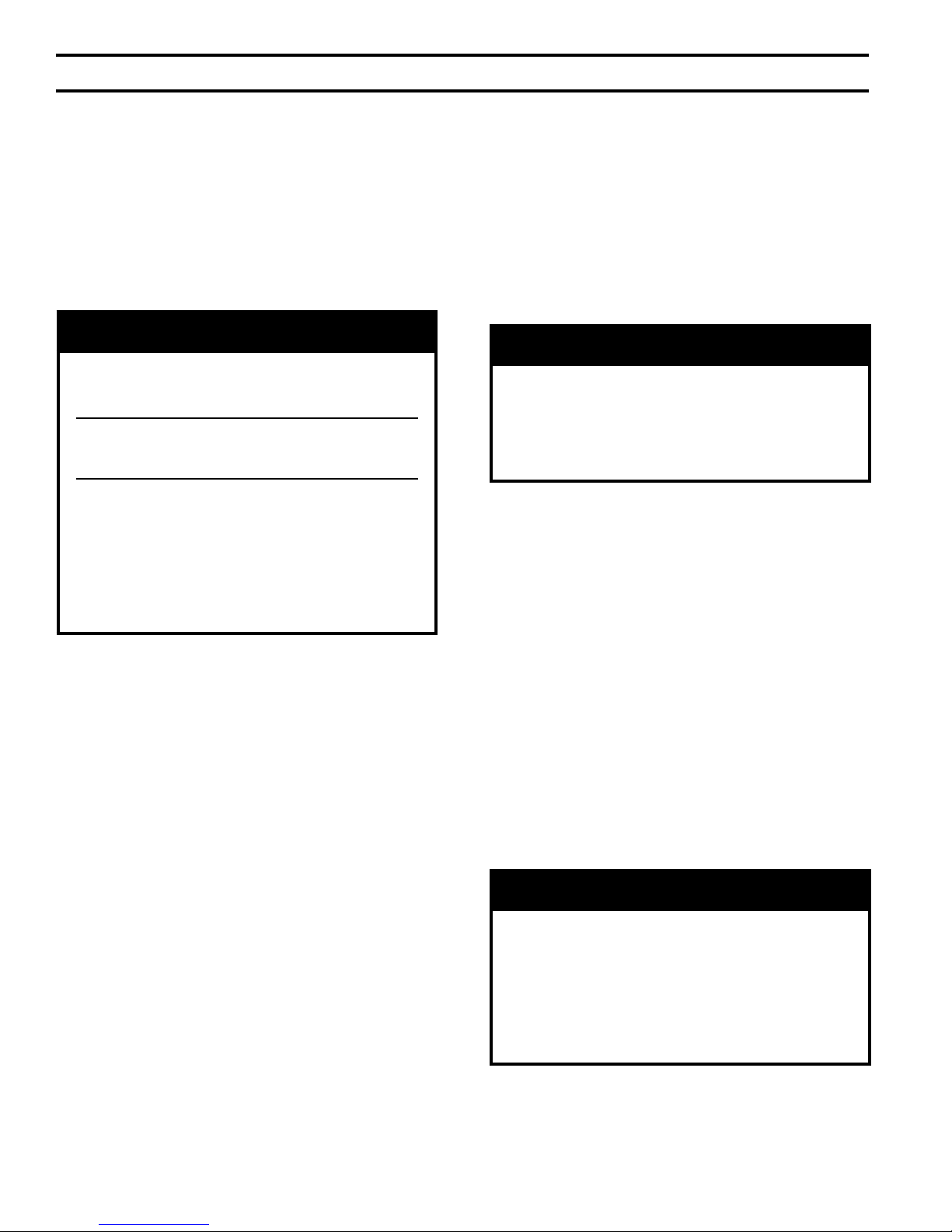
C. Provide clearance between boiler jacket and
combustible material in accordance with local re
ordinance. Refer to Figures 2A and 2B for minimum
listed clearances from combustible material.
Recommended service clearance is 24 inches from left
side, front, top and rear of the boiler. Recommended
front clearance may be reduced to the combustible
material clearance providing:
1. Access to boiler front is provided through a door or
removable front access panel.
2. Access is provided to the condensate trap located
underneath the heat exchanger.
D. Protect gas ignition system components from water
(dripping, spraying, rain, etc.) during boiler operation
and service (circulator replacement, condensate trap,
control replacement, etc.).
E. Provide combustion and ventilation air in accordance
with applicable provisions of local building codes,
or: USA - National Fuel Gas Code, NFPA 54/ANSI
Z223.1, Air for Combustion and Ventilation;
Canada - Natural Gas and Propane Installation Code,
CAN/CSA-B149.1, Venting Systems and Air Supply for
Appliances.
WaRning
F. The boiler should be located so as to minimize the
length of the vent system. The PVC combustion
air piping, or the optional concentric vent piping,
containing integral combustion air inlet piping, must
terminate where outdoor air is available for combustion
and away from areas that may contaminate combustion
air. In particular, avoid areas near chemical products
containing chlorines, chlorouorocarbons , paint
removers, cleaning solvents and detergents. Avoid
areas containing saw dust, loose insulation bers, dry
wall dust etc.
CaUTiOn
avoid operating this boiler in an environment
where saw dust, loose insulation bers, dry wall
dust, etc. are present. if boiler is operated under
these conditions, the burner interior and ports
must be cleaned and inspected daily to insure
proper operation.
G. General.
1. Alpine boilers are intended for installations in an
area with a oor drain, or, in a suitable drain pan to
prevent any leaks or relief valve discharge to cause
property damage
2. Alpine boilers are not intended to support external
piping and venting. All external piping and venting
must be supported independently of the boiler.
3. Alpine boilers must be installed level to prevent
condensate from backing up inside the boiler.
4. Alpine boilers can be installed either as oor
standing (ALP080 thru ALP500), or, as wall hung
(ALP080 thru ALP210). Factory assembled oor
standing models are identied with sufx F in a
boiler model code (example – ALP210F-1L02).
Factory assembled wall hung models are identied
with sufx W in a boiler model code (example
– ALP210W-1L02).
5. Boiler Floor Standing Installation:
a. For basement installation provide a solid base
such as concrete, where oor is not level, or,
water may be encountered on the oor around
boiler. Floor must be able to support weight
of boiler, water and all additional system
components.
b. Boiler must be level to prevent condensate from
backing up inside the boiler.
c. Insure there is adequate space for condensate
piping or a condensate pump if required.
Adequate combustion and ventilation air must
be provided to assure proper combustion.
13
ii. Pre-installation & Boiler Mounting (continued)
6. Boiler Wall Hung Installation:
a. If the boiler is installed on a framed wall,
minimum acceptable framing is 2 x 4 studs on
16” centers. The boiler mounting holes are on
16” centers for installation between two studs
at the standard spacing. In cases where the
boiler cannot be centered between the studs, or
where the studs are spaced closer than 16” apart,
the boiler may be anchored to ¾” plywood or
horizontal 2 x 4’s anchored to the studs.
CaUTiOn
alpine boiler approximate dry weights:
aLP080W – 98 lbs; aLP105W – 112 lbs;
aLP150W – 136 lbs: aLP210W – 150 lbs
Two people are required to safely lift these
boilers onto the installed wall mounting
bracket.
Make sure that wall mounting bracket is anchored to a structure capable of supporting
the weight of the boiler and attached piping
when lled with water. Jurisdictions in areas
subject to earthquakes may have special re-
quirements for supporting these boilers. Such
local requirements take precedence over the
requirements shown below.
b.
Locate Wall Mounting Bracket Kit carton (p/n
102988-01) enclosed inside boiler carton. The
kit contains Wall Mounting Bracket, Bottom
Securing Bracket, (4) 5/16” x 2” long hex head
lag screws, (4) 5/16” at plated washers and (2)
#8 x ½” Phillips round head sheet metal screws.
5/16” x 2” lag screws and 5/16” plated washers
c.
are intended for mounting the boiler directly
onto studs covered with ½” sheet rock. When the
boiler is attached to other types of construction,
such as masonry, use fasteners capable of
supporting the weight of the boiler and attached
piping in accordance with good construction
practice and applicable local codes.
d. Make sure that the surface to which the boiler is
mounted is plumb.
e. Before mounting the boiler, make sure that wall
selected does not have any framing or other
construction that will interfere with the vent pipe
penetration.
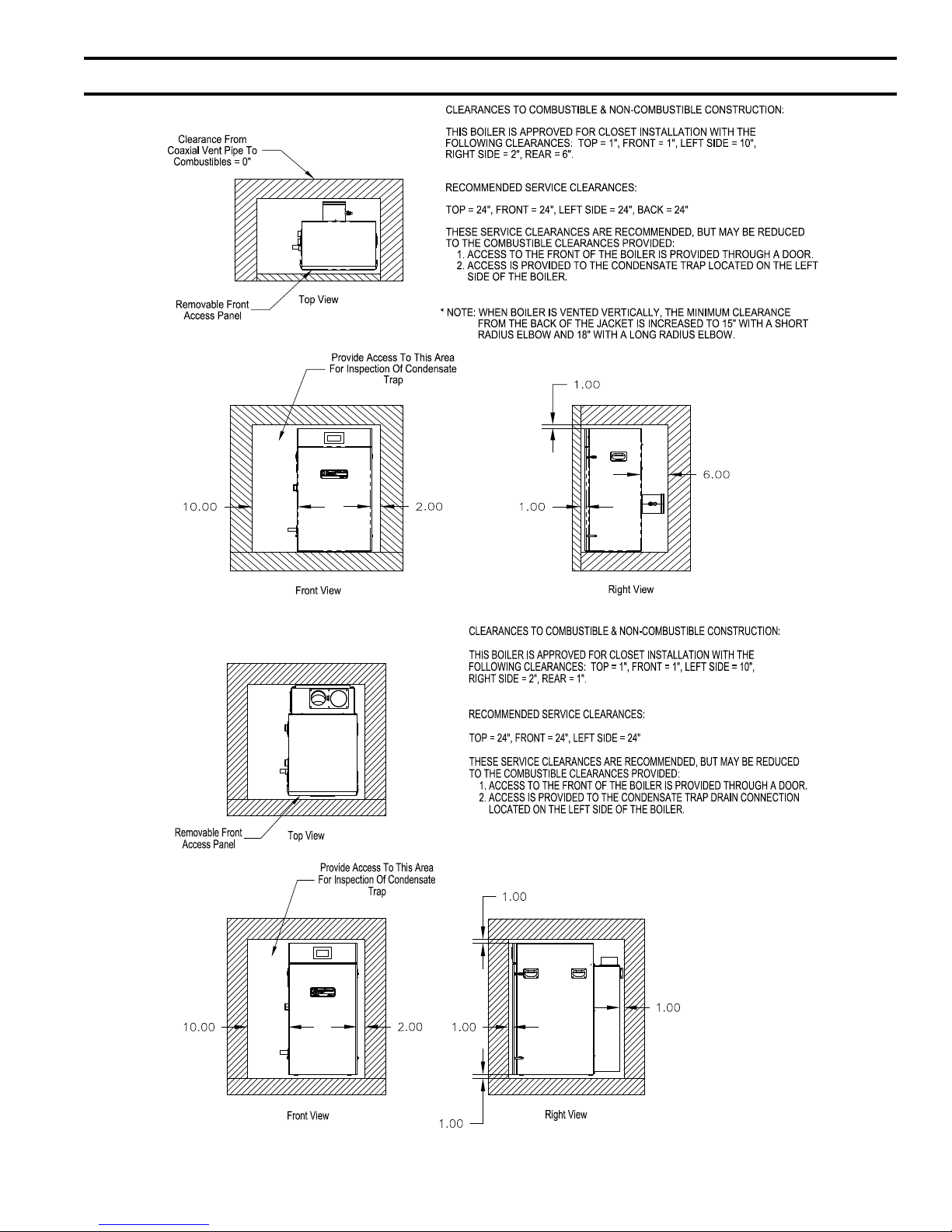
f. Once a suitable location has been selected for the
boiler, and any needed modications have been
made to the wall, use Figure 2C to locate and
layout holes “A” and “B”. These holes must be
positioned on mounting stud centers, if the boiler
is installed on a framed wall. Make sure that
the horizontal centerline of these holes is level.
Holes “C” and “D” may also be drilled at this
time, or after the boiler is hung on the wall. If the
5/16 x 2” lag screws are used, drill 3/16” pilot
holes.
g. An alternate way to locate/mark holes “A”
and “B” is to use template P/N 102986-01
enclosed into Vent Part Carton [P/N 10298101 (ALP080W/105W) or, P/N 102981-02
(ALP150W/210W)], which can be found inside
boiler carton.
CaUTiOn
The outer edges of the template represent
minimum side, top and bottom clearances to
combustible material. if the template needs to be
cut to t into a selected location, it would indicate
the minimum clearances to combustible material
are not met.
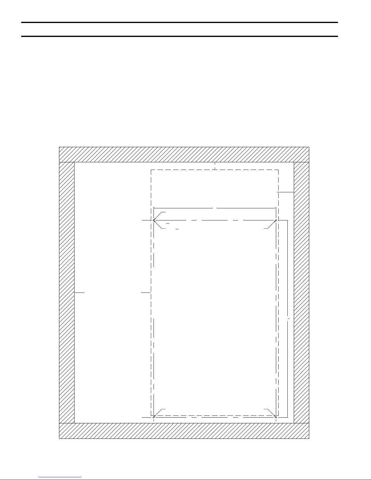
h. Attach the wall hanging bracket using the 5/16”
x 2” lag screws and 5/16” plated washers, or
other suitable anchors as appropriate (Figure
2D). Make sure the bracket is level.
Attach Bottom Securing Bracket to boiler air box
i.
with two #8 x ½” Phillips round head sheet metal
screws. Refer to Figure 2D for details.
j. Hang the boiler on the installed wall bracket as
shown in Figure 2D.
k. If not already done in Step (4) locate and drill
holes “C” and “D” using the ob-round slots in
the Bottom Securing Bracket. Secure the Bracket
to the wall using the 5/16” x 2” lag screws
and 5/16” plated washers, or other fasteners as
appropriate (Figure 2D).
l. Verify that the front of the boiler is plumb. If it
is not, install shims (installer provided) at holes
“C” and “D” between the Bottom Securing
Bracket and the wall to adjust.
CaUTiOn
When positioning the template in the desired
location on the wall insure that the minimum
clearances to combustible material at
adjacent walls and ceiling are maintained. Consult
Figures 2a thru 2C in this manual. Be sure to
allow space at the boiler left side for gas and
water connections, as well as for access to the
condensate trap and boiler controls for servicing.
m. Remove Access Panel and Access Panel Gasket
from zip lock plastic bag (placed inside 10298101 or 102981-02 Vent Kit carton).
14
ii. Pre-installation & Boiler Mounting (continued)
Figure 2a: Clearances To Combustible and non-combustible Material, Floor Standing
Figure 2B: Clearances To Combustible and non-combustible Material, Wall Mounted
15
TOP EDGE OF BOILER
'HOLE C'
'HOLE A'
'HOLE D'
LEFT SIDE OF BOILER
1.0" MIN. CLEARANCE TO COMBUSTIBLE
10.0" MIN. CLEARANCE TO COMBUSTIBLES
16
25
3
4
WALL MOUNTING BRACKET
CENTER LINE
BOTTOM SECURING
BRACKET CENTER LINE
2.0" MIN. CLEARANCE TO COMBUSTIBLE
'HOLE B'
3
16
" DIA. PILOT HOLES
FOR
5
16
" LAG SCREWS
(4 PLACES)
ii. Pre-installation & Boiler Mounting (continued)
n. Place Access Panel Gasket adhesive side
(protective paper) down onto Access Panel
underside and align gasket edges ush with panel
edges. Peel off protective paper from one end
of the gasket to expose adhesive, then place the
gasket onto the panel aligning gasket and panel
side, top and bottom edges, and press the gasket
lightly down. Continue peeling of protective
paper and positioning the gasket in place while
insuring edge alignment. Once the gasket is
fully in place and edges are aligned, press the
gasket rmly in position.
o. Set the panel with gasket aside.
p. See Section IV Venting; paragraph “Field
Installation of CPVC Vent Pipe - Wall Mounted
Boiler Builds” for instructions on attaching the
vent system to the boiler.
q. After the boiler has been piped, wired, connected
to vent and combustion air system piping and
combustion performance testing completed per
Section XI “System Start-up”, install Access
Panel/Gasket assembly and secure with provided
four #8 x ½” black oxide Phillips head sheet
metal screws (located in coin envelope inside zip
lock plastic bag). See Figure 2E “access Panel
and Gasket Installation”.
Figure 2C: Wall Mounting Hole Location / Layout
16
ii. Pre-installation & Boiler Mounting (continued)
iii. Unpacking Boiler
CaUTiOn
Figure 2D: Bottom Mounting Bracket installation / Boiler Wall Mounting
Figure 2E: access Panel and gasket installation
D. Remove boiler from cardboard positioning sleeve on
shipping skid.
Do not drop boiler.
A. Move boiler to approximate installed position.
B. Remove all crate fasteners.
C. Lift and remove outside container.
WaRning
installation of this boiler should be undertaken
only by trained and skilled personnel from a
qualied service agency.
E. Move boiler to its permanent location.
17
iV. Venting
WaRning
Failure to vent this boiler in accordance with these instructions could cause products of combustion to
enter the building resulting in severe property damage, personal injury or death.
Do not interchange vent systems or materials unless otherwise specied.
The use of thermal insulation covering pipe and ttings is prohibited.
Do not use a barometric damper, draft hood or vent damper with this boiler.
When using the CPVC/PVC vent option, the use of CPVC is required when venting in vertical or horizontal
chase ways.
The CPVC vent materials supplied with this boiler do not comply with B1
proved for use in Canadian jurisdictions that require vent systems be listed to ULC S636-2008. In
these jurisdictions, vent this boiler using either stainless steel Special
Class iiB venting system.
Do not locate vent termination where exposed to prevailing winds. Moisture and ice may form on
surface around vent termination. To prevent deterioration, surface must be in good repair (sealed,
painted, etc.).
Do not locate air intake vent termination where chlorines, chlorouorocarbons (CFC’s), petroleum
distillates, detergents, volatile vapors or other chemicals are present. Severe boiler corrosion and
failure will result.
The use of cellular core PVC (
aSTM F891) is prohibited.
49.1.S1-07 and are not ap-
gas vent or a listed ULC S636
Do not locate vent termination under a deck.
Do not reduce specied diameters of vent and combustion air piping.
When installing vent pipe through chimney, as a chase, no other appliance can be vented into the
chimney.
Do not allow low spots in the vent where condensate may pool.
A. General Guidelines
1. Vent system installation must be in accordance
with National Fuel Gas Code, NFPA 54/ANSI
Z221.3 or applicable provisions of local building
codes. Contact local building or re ofcials about
restrictions and installation inspection in your area.
2. The Alpine™ is designed to be installed as a
Direct Vent (sealed combustion) boiler. The air
for combustion is supplied directly to the burner
enclosure from outdoors and ue gases are vented
directly outdoors (through wall or roof).
3. The following combustion air/vent system options
are approved for use with the Alpine™ boilers (refer
to Table 3):
• Two-Pipe CPVC/PVC Vent/Combustion Air
System - separate CPVC/PVC pipe serves to
expel products of combustion and separate PVC
pipe delivers fresh outdoor combustion air.
Refer to Part B for specic details.
• Two-Pipe Stainless Steel Vent/Combustion Air
System - separate stainless steel pipe serves to
expel products of combustion. Separate PVC or
galvanized pipe delivers fresh outdoor air. Refer
to Part C for specic details.
• Concentric Inner Polypropylene Vent
and Outer Steel Combustion Air System
- the assembly consists of inner re resistant
polypropylene vent pipe and outer steel pipe
casing. The inner pipe serves as conduit to
expel products of combustion, while outdoor
fresh combustion air is drawn through the space
between the inner and outer pipes. Refer to Part
D for specic details.
Horizontal vent pipe must maintain a 1/4" per foot
4.
slope down towards the boiler.
5. Horizontal combustion air pipe must maintain a
minimum ¼" per foot slope down towards terminal,
when possible. If not, slope toward boiler.
6. Do not install venting system components on
the exterior of the building except as specically
required by these instructions (refer to Figure 3):
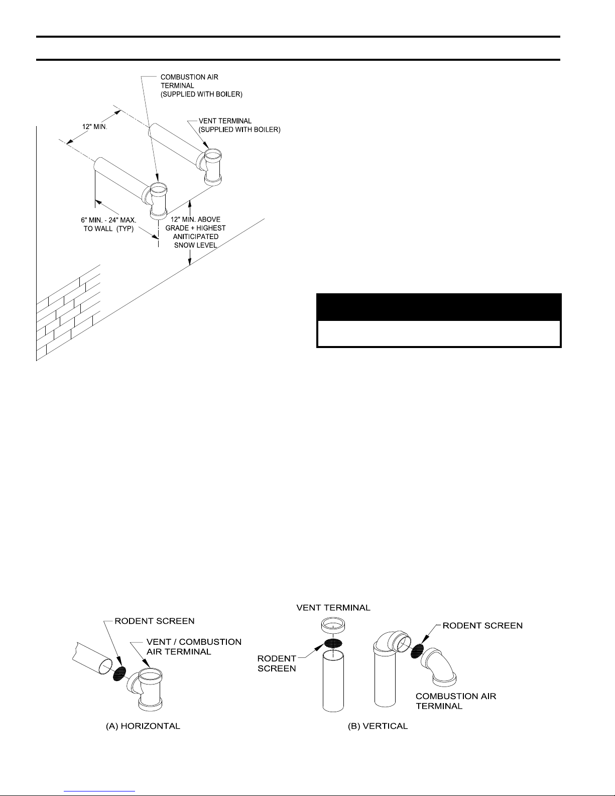
• Vent terminals must be at least 1 foot from any
door, window, or gravity inlet into the building.
• Maintain the correct clearance and orientation
between the vent and air intake terminals. The
vent and air intake terminals must be at the same
height and their center lines must be spaced apart
12” minimum. Locate air intake termination on
the same wall as the vent termination if possible,
18
iV. Venting (continued)
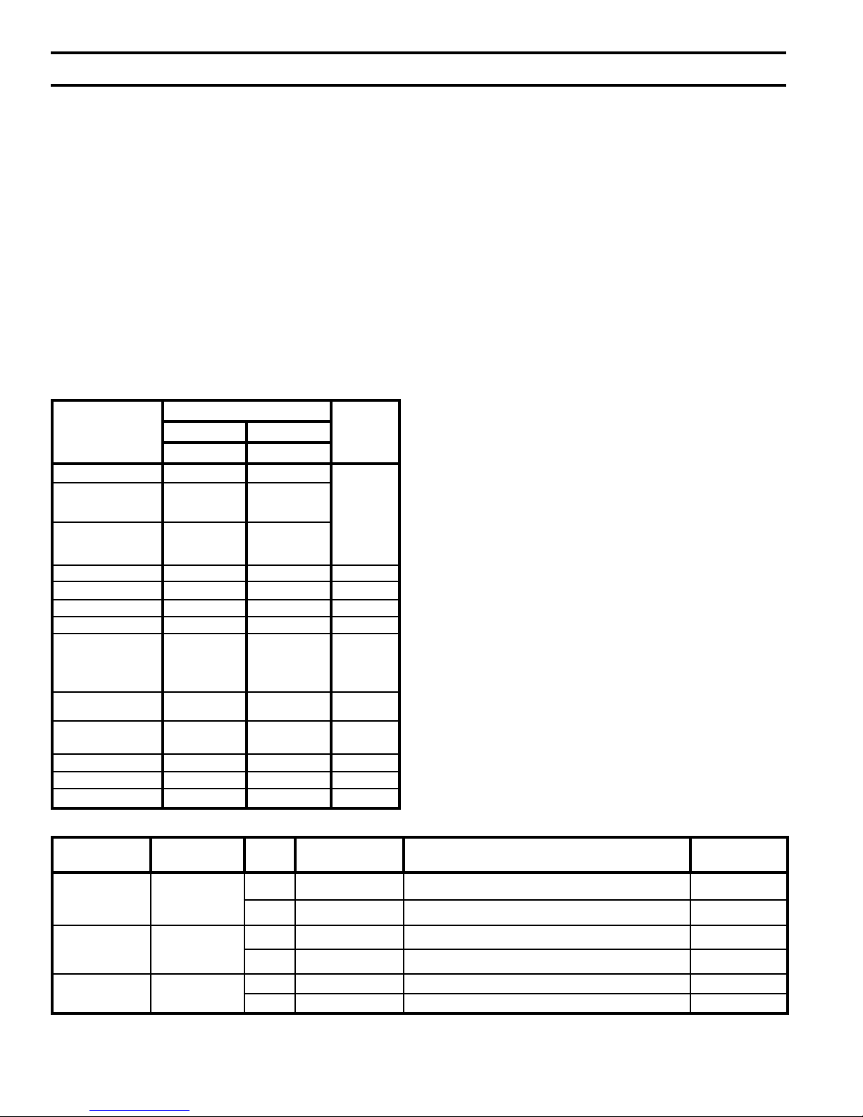
Table 3: Vent/Combustion air System Options
Boiler Build
Floor Standing
or Wall Hung
Floor Standing
Only
Floor Standing
Only
Approved Direct
Vent System
Two-Pipe,
CPVC/PVC
Vent and PVC
air intake
(Factory Standard)
Two-Pipe,
Stainless Steel Vent
and PVC/galvanized
steel air intake
(Available Optional)
Concentric, Inner
Polypropylene Vent
and Outer Steel Air
intake (Available
Optional)
Vent
Material
CPVC/PVC
Stainless Steel
Polypropylene
Orientation Termination Description Figures
The system includes separate
CPVC vent pipe and PVC air intake
pipe terminating thru sidewall with
individual penetrations for the vent
and air intake piping and separate
terminals (tees).
Same as above but separate snorkel
type terminals.
The system includes separate CPVC
vent pipe and PVC air intake pipe
terminating thru roof with individual
penetrations for the vent and air
intake piping and separate vertical
terminals.
The system includes separate
stainless steel vent pipe and
PVC/galvanized steel air intake
pipe terminating thru sidewall with
individual penetrations for the vent
and air intake piping and separate
terminals
Same as above but separate snorkel
type terminals.
The system includes separate
stainless steel vent pipe and
PVC/galvanized steel air intake pipe
terminating thru roof with individual
penetrations for the vent and air
intake piping and separate terminals.
Concentric vent/air pipe terminates
thru sidewall.
Concentric vent/air pipe terminates
thru roof.
4 thru 9 4A
4, 5A, 5B,
6, 7, 9, 10
4, 5A, 5B,
6, 9, 11
8, 13
10, 13
11, 12, 13
14 thru 21
14, 15,
16, 17,
22 thru 26
Horizontal
Optional Vertical
Horizontal
Vertical
Horizontal
Vertical
Standard
(thru sidewall)
Optional
Snorkel
(thru sidewall)
Vertical
(thru roof)
Standard
(thru sidewall)
Optional
Snorkel
(thru sidewall)
Vertical
(thru roof)
Horizontal
(Wall) Terminal
Vertical (Roof)
Terminal
Component
Table
4B
4C
8A & 8B C.
10 D.
Part
B.
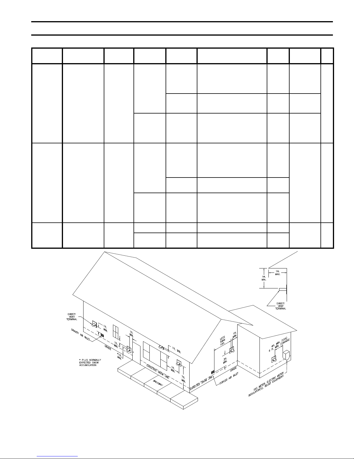
Figure 3: Location of Vent Terminal Relative to Windows, Doors, grades, Overhangs, Meters and Forced air
inlets (Concentric Terminal Shown - Two-Pipe System Vent Terminal to be installed in same location Two-Pipe System air intake Terminal not Shown)
19
iV. Venting (continued)
to prevent nuisance boiler shutdowns. However,
boiler may be installed with vertical venting
and sidewall combustion air inlet or visa versa,
if installation conditions do not allow alternate
arrangement.
• The bottom of the vent and air intake terminal
must be at least 12" (18" in Canada) above the
normal snow line. In no case should they be less
than 12" above grade level.
• The bottom of the vent terminal must be at least
7 feet above a public walkway.
• Do not install the vent terminal directly over
windows or doors.
• The bottom of the vent terminal must be at least
3 feet above any forced air inlet located within
10 feet.
• A clearance of at least 4 feet horizontally must
be maintained between the vent terminal and
gas meters, electric meters, regulators, and relief
equipment. Do not install vent terminal over this
equipment.
• Do not locate the vent terminal under decks or
similar structures.
• Minimum twelve (12) inches vertically from any
roof overhang twelve (12) inches or less wide.
If a roof overhang width exceeds twelve (12)
inches the terminal vertical clearance must be
increased to avoid ue vapor condensation.
• Top of vent terminal must be at least 5 feet below
eaves, softs, or overhangs. Maximum depth of
overhang is 3 ft.
• If window and/or air inlet is within four (4) feet
of an inside corner, then terminal must be at least
six (6) feet from adjoining wall of inside corner.
• Concentric - Minimum twelve (12) inches
horizontally from a building corner.
• Under certain conditions, water in the ue gas
may condense, and possibly freeze, on objects
around the terminal including on the structure
itself. If these objects are subject to damage by
ue gas condensate, they should be moved or
protected.
• If possible, install the vent and air intake
terminals on a wall away from the prevailing
wind. Reliable operation of this boiler cannot be
guaranteed if the terminal is subjected to winds
in excess of 40 mph.
• Air intake terminal must not terminate in areas
that might contain combustion air contaminates,
such as near swimming pools.
• For sidewall venting the minimum horizontal
distance between any adjacent individual module
(boiler) vent terminations is twelve (12) inches.
Increasing this distance is recommended to avoid
frost damage to building surfaces where vent
terminations are placed.
CaUTiOn
installing multiple individual module (boiler) vent
terminations too close together may result in cross
contamination and combustion product water
vapor condensation on building surfaces, where
vent termination are placed, and subsequent
frost damage. To avoid/minimize frost damage,
extend the distance from building surfaces to
vent termination end and increase the horizontal
distance between adjacent vent terminations.
• The minimum horizontal distance between any
adjacent individual module (boiler) roof vent
terminations is one (1) foot.
Use noncombustible ¾" pipe strap to support
7.
horizontal runs and maintain vent location and
slope while preventing sags in pipe. Do not restrict
thermal expansion or movement of vent system.
Maximum support spacing four (4) feet. Avoid low
spots where condensate may pool. Do not penetrate
any part of the vent system with fasteners.
8. Maintain minimum clearance to combustible
materials. See Figures 2A and 2B for details.
9. Enclose vent passing through occupied or
unoccupied spaces above boiler with the material
having a re resistance rating of at least equal to the
rating of adjoining oor or ceiling.
Note: For one or two family dwellings, re
resistance rating requirement may not need to be
met, but is recommended.
10. Multiple individual module vertical vent pipes may
be piped through a common conduit or chase so that
one roof penetration may be made.
20
iV. Venting (continued)
B. CPVC/PVC Venting
WaRning
WaRning
all CPVC vent components (supplied with boiler)
must be used for near-boiler vent piping before
transitioning to Schedule 40 PVC pipe (aSTM
2665) components for remainder of vent system.
WaRning
CPVC vent components must be used within any
interior space where air cannot circulate freely,
such as air inside a stud wall, and in any boiler
closet.
Table 4a: CPVC/PVC Vent & air intake Components included With Boiler
LP080 & aLP105
Vent & air intake Components
3” Schedule 40 PVC Tee (Vent & Air Intake
Terminals)
4” Schedule 40 PVC Tee (Vent & Air Intake
Terminals)
3” Stainless Steel Rodent Screen 102191-01 2 1 N/A
4” Stainless Steel Rodent Screen 102191-02 N/A 1 2
3” x 30” Schedule 40 CPVC Pipe 102193-01 1 1 N/A
4” x 30” Schedule 40 CPVC Pipe 102193-02 N/A N/A 1
3” Schedule 80 CPVC 90° Elbow 102192-01 1 1 1
4” Schedule 80 CPVC 90° Elbow 102192-02 N/A N/A 1
4 oz. Bottle of Transition Cement 102195-01 1 1 1
4 oz. Bottle of Primer 102194-01 1 1 1
3" Vent/3" Combustion Air CPVC/PVC
Connector
3" Vent/4" Combustion Air CPVC/PVC
Connector
4" Vent/4" Combustion Air CPVC/PVC
Connector
3" Vent/3" Combustion Air CPVC/PVC
Connector Gasket
4" Vent/4" Combustion Air CPVC/PVC
Connector Gasket
Part
n
umber
102190-01 2 1 N/A
102190-02 N/A 1 2
102183-01 1 N/A N/A
102183-02 N/A 1 N/A
102183-03 N/A N/A 1
102185-01 1 N/A N/A
102185-02 N/A 1 1
Table 4B: CPVC/PVC Vent & Air Intake Components (Installer Provided) required for Optional Vertical
(Roof) Termination
Vent Components
3" Schedule 40 PVC Coupler
4" Schedule 40 PVC Coupler N/A 1 1
3" Schedule 40 PVC 90° Elbow
4" Schedule 40 PVC 90° Elbow
3" Schedule 40 CPVC Pipe x ½ ft. min. horizontal run
4" Schedule 40 CPVC Pipe x ½ ft. min. horizontal run
a
Standard Termination
(P/
Part
number
N/A
Supplied by
Others
When using the CPVC/PVC vent options, the use
of CPVC is required when venting in vertical or
horizontal chase ways.
Components and Length Restrictions
1.
a. See Table 4A for CPVC/PVC Vent & Air Intake
Components included with boiler, Table 4B for
CPVC/PVC Vent and Air Intake Components
(Installer Provided) required for Optional
Vertical (Roof) Termination and Table 4C for
CPVC/PVC Vent and Air Intake Components
(Installer Provided) required for Optional
Horizontal (Snorkel) Termination.
Quantity
Vent Kit
n 102189-01)
includes
LP080 & aLP105
a
Vertical (Roof)
Termination
1 N/A N/A
2 N/A N/A
N/A 2 2
1
N/A 1 1
aLP150 & aLP210
Standard Termination
Vent Kit
(P/n 102189-02)
includes
Quantity
LP150 & aLP210
a
Vertical (Roof)
Termination
N/A
aLP285 thru aLP500
Standard Termination
(P/n 102189-03)
aLP285 thru aLP500
Vertical (Roof)
Termination
Vent Kit
includes
N/A
21
iV. Venting (continued)
Table 4C: CPVC/PVC Vent & Air Intake Components (Installer Provided) required for Optional Horizontal
(Snorkel) Termination
Quantity
Vent Components
3" Schedule 40 PVC Pipe x up to 7 ft. max. vertical run
4" Schedule 40 PVC Pipe x up to 7 ft. max. vertical run N/A 1 2
3" Schedule 40 PVC 90° Elbow
4" Schedule 40 PVC 90° Elbow
3" Schedule 40 PVC Pipe x ½ ft. min. horizontal run
4" Schedule 40 PVC Pipe x ½ ft. min. horizontal run
Part
number
N/A
Supplied by
Others
LP080 & aLP105
a
Horizontal (Snorkel)
Termination
2 1 N/A
4 2 N/A
N/A 2 4
2 1 N/A
N/A 1 2
Table 5: Clearances from Vent Piping to Combustible Material
Vent Pipe Pipe Direction Enclosure
CPVC/PVC Venting Vertical or Horizontal Enclosed at all Sides See Figures 2A and 2B
Table 6: Vent System and Combustion air System Components
LP150& aLP210
a
Horizontal (Snorkel)
Termination
Minimum Clearance To
Combustible Material
aLP285 thru aLP500
Horizontal (Snorkel)
Termination
Vent System Component Equivalent Length (Ft.)
Schedule 40 CPVC Pipe x 30 Inches 2.5
Schedule 80 CPVC 90° Elbow 5
WaRning
all condensate that forms in the vent must be
able to drain back to the boiler.
Vent length restrictions are based on equivalent
b.
length of vent/combustion air pipe (total length
of straight pipe plus equivalent length of
ttings). Maximum vent/combustion air lengths
are listed in Table 7. Do not exceed maximum
vent/combustion air lengths. Table 6 lists
equivalent lengths for ttings. Do not include
vent/combustion air terminals in equivalent
feet calculations. See “Combustion Air/Vent,
Equivalent Length Work Sheet”.
c. The vent termination location is restricted as per
'General Guidelines', Paragraph A, 5.
(Refer to Figure 3).
2. System Assembly
a. Plan venting system to avoid possible contact
with plumbing or electrical wires. Start at
vent connector at boiler and work towards vent
termination.
b. Do not exceed maximum Vent/Combustion Air
length. Refer to Table 7.
Combustion Air
System Component
(Parts by Others)
Pipe x 1 Ft. 1
Pipe x 2 Ft. 2
Pipe x 4 Ft. 4
Pipe x 5 Ft. 5
Elbow 5
Elbow 2.5
*Equivalent Feet of Pipe Based on
Standard 4” PVC Design
Equivalent
Feet of Pipe*
c. Design the Vent System to allow 3/8" of thermal
expansion per 10 feet of CPVC/PVC pipe. Runs
of 20 feet or longer that restrained at both ends
must use an offset or expansion loop. Refer to
Figure 4.
d.
Follow all manufacturer instructions and
warnings when preparing pipe ends for joining
and using the primer and the cement.
3. Field Installation of CPVC/PVC Two-Pipe
Vent System Connector - Floor Mounted
Boiler Builds
Refer to Figure 5 and Steps below:
a. Position the CPVC/PVC vent connector and
gasket onto boiler rear/bottom panel and insert
vent connector inner stainless steel vent pipe into
heat exchanger vent outlet.
b. Align vent connector plate and gasket clearance
holes with rear/bottom panel engagement holes;
than, secure the connector and gasket to the
panel with six mounting screws.
22
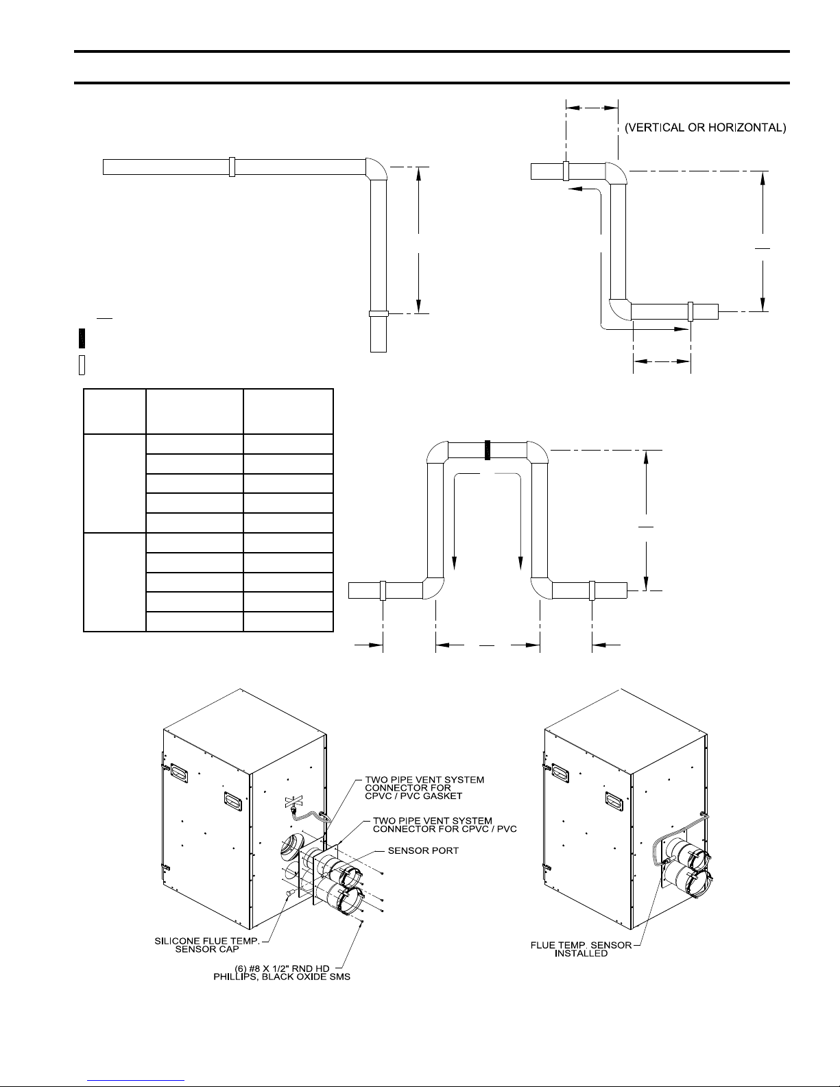
iV. Venting (continued)
2 L
5
6"
MIN
6"
MIN
5
4
4
2
LONG RUN OF PIPE
CHANGE OF DIRECTION
(VERTICAL OR HORIZONTAL)
LOOP
(HORIZONTAL ONLY)
(TOP VIEW)
OFFSET
L
L
L
(L)
LOOP LENGTH
L
L
L
RESTRAINT (RESTRICTS MOVEMENT)
HANGER (ALLOWS MOVEMENT)
KEY
PIPE DIA.
(IN.)
3
4
LENGTH OF
STRAIGHT RUN
(FT.)
20 50
30 61
40 70
50 79
60 86
20 56
30 69
40 80
50 89
60 98
LOOP LENGTH
(L) (IN.)
Figure 4: Expansion Loop and Offset
Figure 5: Field installation of CPVC/PVC Two-Pipe Vent System Connector - Floor Mounted Boiler Builds
23
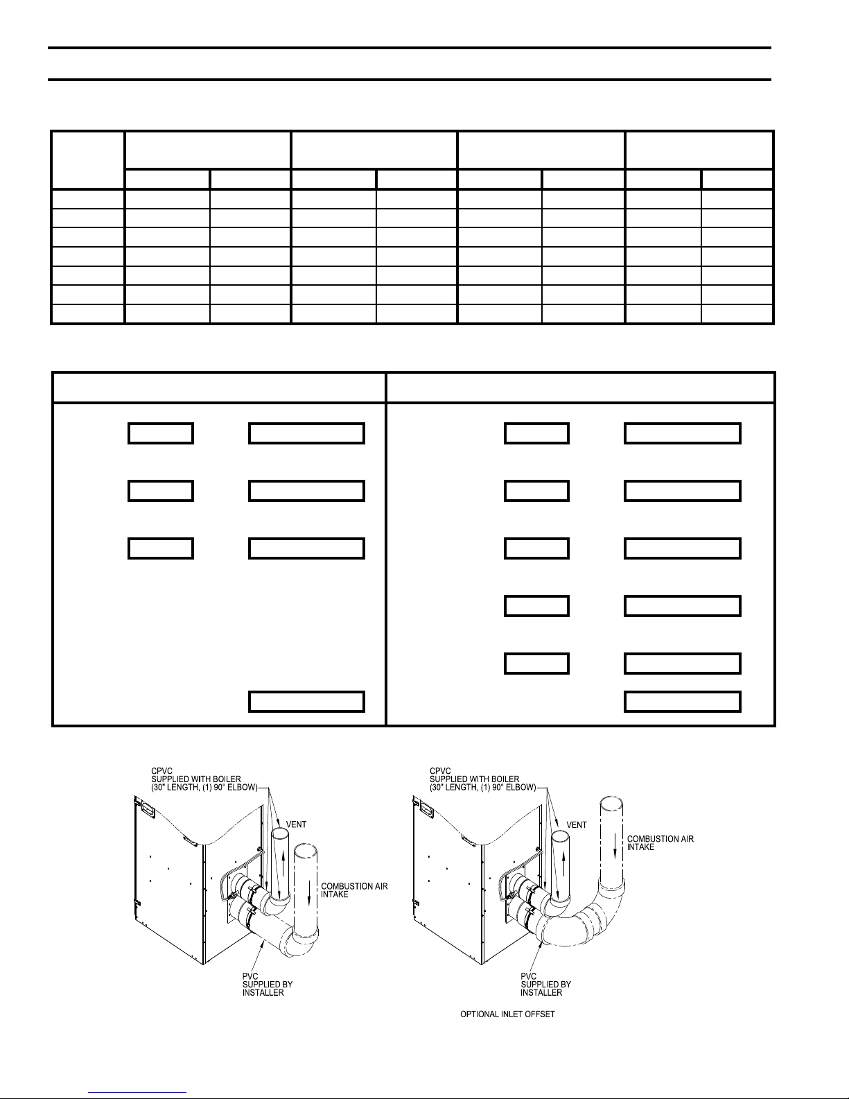
iV. Venting (continued)
Table 7: Vent/Combustion air Pipe Length – Two-Pipe Direct Vent System Options (CPVC/PVC and Stainless
Steel/PVC or galvanized Steel)
Boiler
Model
3” Combustion Air Pipe
(Equivalent Length)
Min. Max. Min. Max. Min. Max. Min. Max.
ALP080 30 In. 100 Ft. --- --- 30 In. 100 Ft. --- --ALP105 30 In. 100 Ft. --- --- 30 In. 100 Ft. --- --ALP150 --- --- 30 In. 100 Ft. 30 In. 100 Ft. --- --ALP210 --- --- 30 In. 100 Ft. 30 In. 100 Ft. --- --ALP285 --- --- 30 In. 60 Ft. --- --- 30 In. 60 Ft.
ALP399 --- --- 30 In. 60 Ft. --- --- 30 In. 60 Ft.
ALP500 --- --- 30 In. 60 Ft. --- --- 30 In. 60 Ft.
Vent/Combustion Air, Equivalent Length Work Sheet
This sheet is supplied to assist in vent/combustion air, equivalent length calculating
Combustion air Vent
90° elbow(s) PVC Supplied 30” straight CPVC
Quantity = x 5 = equiv. ft. a. Length ft. = 2.5 x 1 = 2.5 equiv. ft. a.
4” Combustion Air Pipe
(Equivalent Length)
3” Vent Pipe
(Equivalent Length)
4” Vent Pipe
(Equivalent Length)
45° elbow(s) PVC Supplied 90° elbow CPVC
Quantity = x 2.5 = equiv. ft. b. Quantity = 1 x 5 = 5 equiv. ft. b.
Straight pipe PVC 90° elbow(s) PVC
Length ft. = x 1 = equiv. ft. c. Quantity = x 5 = equiv. ft. c.
45° elbow(s) PVC
Quantity = x 2.5 = equiv. ft. d.
Straight pipe PVC
Length ft. = x 1 = equiv. ft. e.
Total* a.+b.+c. = equiv. ft. Total* a.+b.+c.+d.+e.= equiv. ft.
* Total cannot exceed 60 equiv. ft. length.
Vent and combustion air terminals do not count towards total equiv. ft.
24
Figure 6a: near-Boiler Vent/Combustion air Piping - Floor Mounted Boiler Builds
iV. Venting (continued)
4. Near-Boiler Vent/Combustion Air Piping
- Floor Mounted Boiler Builds
Refer to Figure 6A and the following Steps:
a. All CPVC vent components supplied with boiler
inside vent carton (3” or 4” Schedule 40 x 30”
long CPVC pipe and 3” or 4” Schedule 80 CPVC
90° Elbow) must be used for near-boiler piping
before transitioning to Schedule 40 PVC (ASTM
2665) pipe components for reminder of vent
system. The CPVC 30” long straight pipe may be
cut to accommodate desired vent conguration
provided both pieces are used in conjunction
with CPVC 90° Elbow before any PVC
components are used. Ensure that the CPVC 90°
Elbow is the rst elbow used in the vent system
as it exits the boiler.
b. Clean all vent and combustion air pipe joints
with primer and secure with transition cement
(4-oz. bottles of primer and cement are
supplied with boiler inside vent carton). Follow
application instructions provided on primer and
cement bottles.
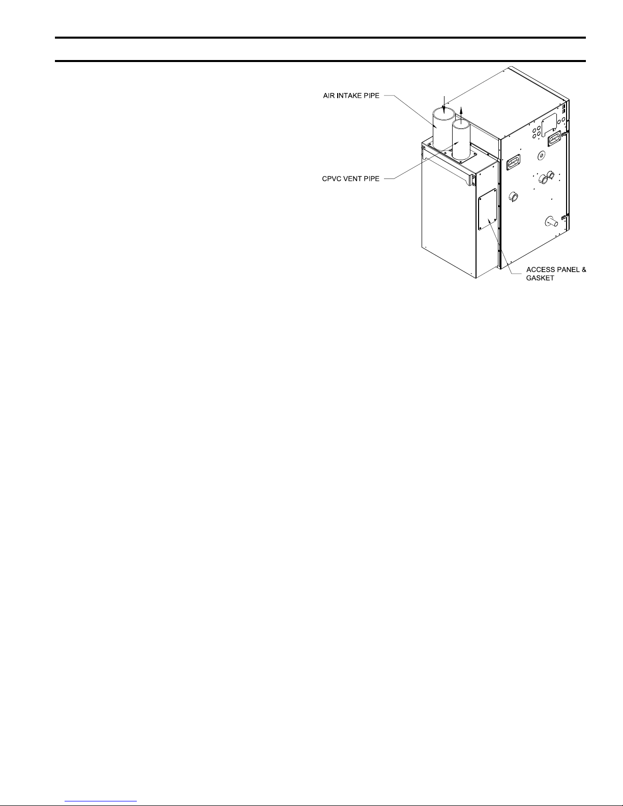
5. Field Installation of CPVC
Mounted Boiler Builds
Refer to Figure 6B and the following Steps:
The wall mounted boiler builds do not require using
3” Schedule 80 CPVC 90° Elbow for near-boiler
vent piping.
a. Insert provided 3” Schedule 40 x 30” long
CPVC pipe thru air box top combination vent/
combustion air collar vent opening and slide
down with a slight twisting motion, until the pipe
lower end is rmly inserted into female end of
factory installed vent connector 90° Elbow.
Secure the pipe by tightening the metal strap
b.
worm screw.
i. The CPVC 30” long straight pipe may be cut
to accommodate desired vent conguration.
If the CPVC 30” straight pipe needs to be
cut into two pieces to accommodate desired
vent conguration, insure that the rst
vertical piece has minimum length of 12
inches and extends 1-5/8” above air box top,
so a coupling or an elbow can be attached to
it.
ii. The factory supplied CPVC vent pipe
(3” Schedule 40 x 30” long CPVC pipe)
must be used for near-boiler piping before
transitioning to Schedule 40 PVC (ASTM
2665) pipe components for reminder of vent
system.
iii. Clean all vent and combustion air pipe
joints with primer and secure with transition
Vent Pipe - Wall
Figure 6B: Field
Figure 7: CPVC/PVC Vent Pipe
Thru Combustible Wall installation
6. Horizontal Vent Termination
a. Standard Two-Pipe Termination
See Figures 7 through 10.
i. Vent Piping
installation of CPVC Vent Pipe -
Wall Mounted Boiler Builds
cement (4-oz. bottles of primer and cement
are supplied with boiler). Follow application
instructions provided on primer and cement
bottles.
• When conditions in Figure 7 cannot
be met, use a single wall thimble [(US
boiler part number 102180-01 (3”) or
102181-01 (4”)] for vent only, when
penetrating a combustible wall. Thimble
25
iV. Venting (continued)
Figure 8 : Direct Vent - Sidewall Terminations
use is optional for non-combustible wall.
Insert thimble from wall from outside.
Secure outside ange to wall with nails
or screws, and seal ID, OD and vent
holes with sealant material. Install inside
ange to inside wall, secure with nails or
screws, and seal with sealant material.
• For noncombustible wall application
when thimble is not used, size opening
such that a minimal clearance is
obtained.
See Figure 7.
• Install Rodent Screen and Vent Terminal
(supplied with boiler), see Figure 9 for
appropriate conguration.
• Apply sealant between vent pipe and
opening/thimble to provide weather-tight
seal. Sealant should not restrain the
expansion of the vent pipe.
ii. Combustion
• Do not exceed maximum combustion air
length. Refer to Table 7.
Size combustion air wall penetration to
•
allow easy insertion of combustion air
piping.
•
Install Rodent Screen and Combustion
Air Terminal (supplied with boiler), see
Figure 9 for appropriate conguration.
Apply sealant between vent pipe and
•
opening to provide weather-tight seal.
b.
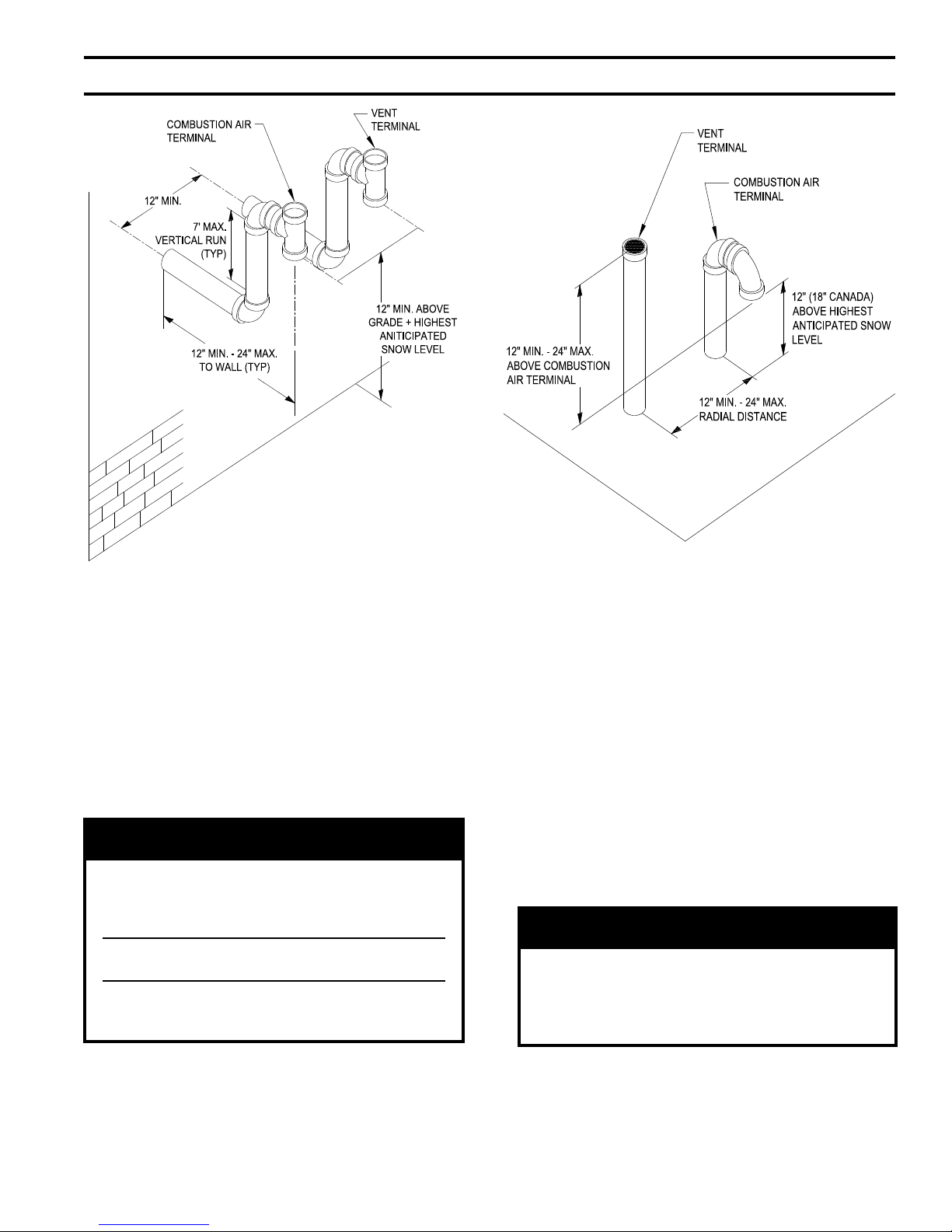
Optional Two-Pipe Snorkel Termination
Refer to Figures 7, 9 and 10.
This installation will allow a maximum of
seven (7) feet vertical exterior run of the vent/
combustion air piping to be installed on the
CPVC/PVC horizontal venting application.
Air Piping
nOTiCE
Exterior run to be included in equivalent vent/
combustion air lengths.
ent Piping
i. V
• After penetrating wall, install a Schedule
40 PVC 90° elbow so that the elbow leg
is in the up direction.
• Install maximum vertical run of seven (7)
feet of Schedule 40 PVC vent pipe. See
Figure 10.
• At top of vent pipe length install another
PVC 90° elbow so that elbow leg is
opposite the building’s exterior surface.
• Install Rodent Screen and Vent Terminal
(supplied with boiler), see Figure 9 for
appropriate conguration.
• Brace exterior piping if required.
ii. Combustion Air Piping
• After penetrating wall, install a Schedule
40 PVC 90o elbow so that elbow leg is in
the up direction.
26
Figure 9: Rodent Screen installation
iV. Venting (continued)
Figure 10: Direct Vent - Optional Sidewall
Snorkel Terminations
• Install maximum vertical run of seven (7)
feet of Schedule 40 PVC vent pipe. See
Figure 10.
• At top of vent pipe length install another
PVC 90° elbow so that elbow leg is
opposite the building’s exterior surface.
• Install Rodent Screen and Combustion
Air Terminal (supplied with boiler), see
Figure 9 for appropriate conguration.
• Brace exterior piping if required.
WaRning
all CPVC supplied with the vent kit must be
used prior to connection of the vent system to
this terminal. if the vent system is too short
to permit this, do not use this terminal.
Do not operate boiler without the rain cap in
place.
Methods of securing and sealing terminals
to the outside wall must not restrain the
thermal expansion of the vent pipe.
Vertical Vent Termination
7.
a. Standard Two-Pipe Termination
Refer to Figures 7, 9, 11 and 12.
Figure 11: Direct Vent - Vertical Terminations
ent Piping
i. V
• Install re stops where vent passes
through oors, ceilings or framed walls.
The re stop must close the opening
between the vent pipe and the structure.
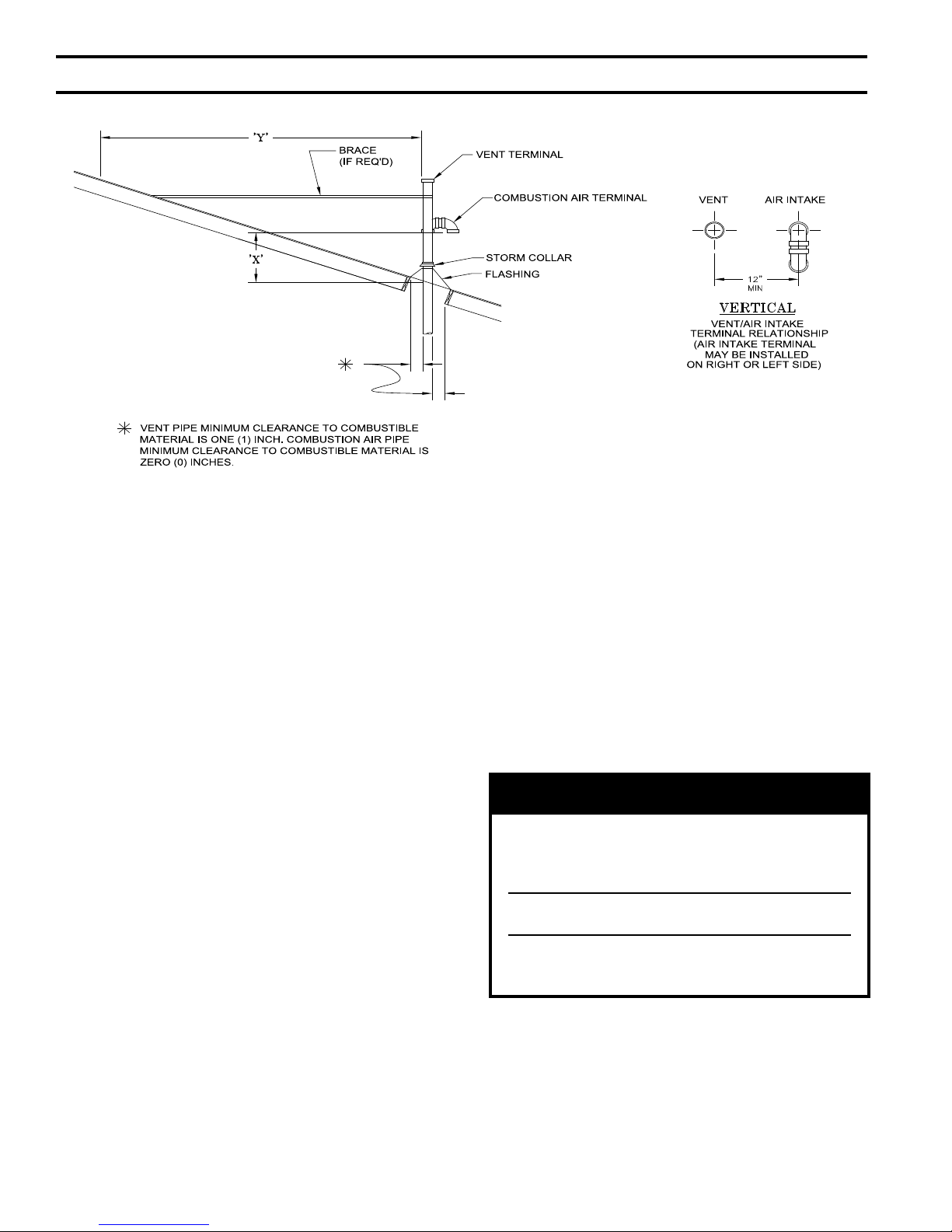
• Whenever possible, install vent straight
through the roof. Refer to Figures 11 and
12.
- Size roof opening to maintain
minimum clearance of 1" from
combustible materials.
Extend vent pipe to maintain minimum
-
vertical and horizontal distance of
twelve (12) inches from roof surface.
additional vertical distance for
expected snow accumulation. Provide
brace as required.
CaUTiOn
Vertical venting and combustion air roof
penetrations (where applicable) require the use
of roof ashing and storm collar, which are not
supplied with boiler, to prevent moisture from
entering the structure.
- Install storm collar on vent pipe
immediately above ashing. Apply
Dow Corning Silastic 732 RTV
Sealant between vent pipe and storm
collar to provide weather-tight seal.
27
iV. Venting (continued)
Figure 12: Direct Vent - Vertical Terminations
with Sloped Roof
Extend vent/combustion air piping to maintain minimum vertical (‘X’) and minimum horizontal (‘Y’) distance of
twelve (12) inches (18 inches Canada) from roof surface. a
snow accumulation.
llow additional vertical (‘X’) distance for expected
• Install Rodent Screen and Vent Terminal
(supplied with boiler), see Figure 9 for
appropriate conguration.
• Brace exterior piping if required.
ii. Combustion Air Piping
• Locate combustion air termination
on the same roof location as the vent
termination to prevent nuisance boiler
shutdowns. Combustion air terminal can
be installed closer to roof than vent.
• Size roof opening to allow easy insertion
of combustion air piping and allow
proper installation of ashing and storm
collar to prevent moisture from entering
the structure.
- Use appropriately designed vent
ashing when passing through roofs.
Follow ashing manufacturers’
instructions for installation
procedures.
- Extend combustion air pipe to
maintain minimum vertical and
horizontal distance of twelve (12)
inches from roof surface. Allow
additional vertical distance for
expected snow accumulation.
Provide brace as required.
- Install storm collar on combustion
air pipe immediately above ashing.
Apply Dow Corning Silastic 732
RTV Sealant between combustion
air pipe and storm collar to provide
weather-tight seal.
• Install Rodent Screen and Combustion
Air Terminal (supplied with boiler), see
Figure 9 for appropriate conguration.
• Brace exterior piping if required.
WaRning
all CPVC supplied with the vent kit must be
used prior to connection of the vent system to
this terminal. if the vent system is too short
to permit this, do not use this terminal.
Do not operate boiler without the rain cap in
place.
Methods of securing and sealing terminals
to the outside wall must not restrain the
thermal expansion of the vent pipe.
28
iV. Venting (continued)
C. Stainless Steel Venting
CaUTiOn
Vent systems made by Heat Fab, Protech and
Z-Flex rely on gaskets or proper sealing. When
these vent systems are used, take the following
precautions:
• Make sure that gasket is in position and un damaged in the female end of the pipe.
• Make sure that both the male and female
pipes are free of damage prior to assembly.
• Only cut vent pipe as permitted by the vent
manufacturer in accordance with their in structions. When pipe is cut, cut end must
be square and carefully de-burred prior to
assembly.
WaRning
all condensate that forms in the vent must be
able to drain back to the boiler.
1.
Vent Length Restrictions
a. Vent length restrictions are based on equivalent
length of vent/combustion air pipe (total length
of straight pipe plus equivalent length of
ttings). Maximum vent/combustion air lengths
are listed in Table 7. Do not exceed maximum
vent/combustion air lengths. Do not include
vent/combustion air terminals in equivalent
feet calculations. See “Combustion Air/Vent,
Equivalent Length Work Sheet”.
b. The vent termination location is restricted as
per 'General Guidelines', Section A.5. (Refer to
Figure 3)
c. Where the use of “silicone” is called for in the
following instructions, use GE RTV 106 or
equivalent for the vent collar. Air inlet piping
sections are sealed with any general-purpose
silicone sealant such as GE RTV102. PVC air
inlet piping sections are connected with PVC
cement.
d. Longitudinal welded seams should not be placed
at the bottom of horizontal sections of exhaust
pipe.
e. Do not drill holes in vent pipe.
f. Do not attempt to mix vent components of
different vent system manufacturers.
2. Near Boiler Connection
To install the stainless steel vent adapter
[P/N 102219-01 (3”). 102220-01 (4”)]:
a. Push the stainless steel vent adapter onto the
CPVC/PVC connector with a slight twisting
motion. Make sure that the stainless steel vent
adapter is inserted at least 1” (refer to Figure 13).
Figure 13: Field installation of Two-Pipe Vent
System adapter for Stainless Steel
b. Secure the adapter to the CPVC/PVC connector
by tightening the metal strap.
3. System Assembly
a. Plan venting system to avoid possible contact
with plumbing or electrical wires. Start at
vent connector at boiler and work towards vent
termination.
b. Refer to Tables 8A and 8B for approved AL29C
Vent Systems.
c. Do not exceed maximum Vent/Combustion air
length. Refer to Table 7.
d. Follow all manufacturer instructions and
warnings when preparing pipe ends for joining
and using the primer and the cement.
e. Assemble the air intake system using either
galvanized or PVC pipe.
i. If PVC piping is used, use PVC cement
to assemble the PVC intake system
components. See Part B for air intake
installation instructions.
ii. If galvanized piping is used, use at least two
sheet metal screws per joint. Seal the outside
of all joints.
4. Horizontal Vent Termination
a. Standard Two-Pipe Termination
Refer to Figure 8.
i. Vent Termination
• Use U.S. Boiler stainless exhaust
terminal [P/N 8110701 (3”), or P/N
100184-01 (4”)]. The outer edge of this
terminal must be between 6" and 12"
from the surface of the wall.
The joint between the terminal and
the last piece of pipe must be outside
of the building.
29
iV. Venting (continued)
• Male end of terminal will t into the
female end of any of the approved
stainless vent systems.
Apply a heavy bead of silicone to the
•
male end of the terminal before inserting
it into the last piece of pipe. Orient the
terminal so that the seam in the terminal
is at 12:00.
• Smooth the silicone over the seam
between the terminal and the last piece
of pipe, applying additional silicone if
necessary to ensure a tight seal.
• Allow the silicone to cure per the
silicone manufacturer’s instructions
before operating the boiler.
Table 8a: U.S. Boiler Vent System Components
(Stainless Steel)
Vent System
Component
SS Vent Kit 102501-01 102501-02
Horizontal Vent
Terminal
(Included in Kit)
PVC to SS Vent
Adapter
(Included In Kit)
Vertical Vent Terminal 102680-01 102680-02 N/A
Pipe x 1 Ft. 8116296U 100176-01 1
Pipe x 3 Ft. 8116298U 100177-01 3
Pipe x 5 Ft. 8116300U 100178-01 5
Pipe x Adjustable 8116319U 100179-01
90° Elbow 8116294U 100180-01
45° Elbow 8116292U 100181-01
Horizontal Drain Tee 8116302U 100182-01 2
Vertical Drain Tee 8116304U 100183-01 7½
Single Wall Thimble 8116116 100184-01 N/A
Part Numbers
ALP080 - 210 ALP285 - 500
3" Vent 4" Vent
8116310 8116313
102219-01 102220-01
Equivalent
Feet of Pipe
N/A
Equal to
Installed
Length
(1.06 to 1.64)
5.5 (3")
8.0 (4")
4.0 (3")
4.5 (4")
ii. Combustion
Air Termination
• Horizontal intake terminal is a tee in the
upright position. Tee should protrude
the same distance from the wall as the
exhaust terminal. See Figure 8.
• Install a rodent screen (not supplied) in
the inlet terminal. Use a screen having
1/2”
(2 x 2) or larger mesh.
b. Optional Two-Pipe Snorkel Termination
Refer to Figure 10.
This installation will allow a maximum of
seven (7) feet vertical exterior run of the vent/
combustion air piping to be installed on the
approved AL29C Stainless Steel horizontal
venting application.
i. Vent Termination
• After penetrating wall, install the
appropriate manufacturer's 90° elbow so
that the elbow leg is in the up direction.
• Install maximum vertical run of seven
(7) feet of appropriate manufacturer's
vent pipe. See Figure 10.
• At top of vent pipe length install another
appropriate manufacturer's 90° elbow
so that the elbow leg is opposite the
building's exterior surface.
• Install horizontal vent terminal.
• Brace exterior piping if required.
ii. Combustion
Air Termination
• After penetrating wall, install a 90°
elbow so that the elbow leg is in the up
direction.
Install maximum vertical run of seven
•
(7) feet of combustion air pipe. See
Figure 10.
• At top of vent pipe length install another
90° elbow os that the elbow leg is
opposite the building's exterior surface.
Table 8B: alternate Vent Systems and Vent Components (Stainless Steel)
Manufacturer
Protech
Systems
Inc..
Z-Flex
Flex-L Intl. Star-34
Vent
System
FasNseal
SVE
Series III
(“Z-Vent III”)
Size Wall Thimbles Horizontal Termination
3 FSWT3 Tee: FSTT3 FSBS3
4 FSWT4 Tee: FSTT4 FSBS4
3 2SVSWTEF03 Tee: 2SVSTTF03 24SVSTPF03
4 2SVSWTEF04 Tee: 2SVSTTF04 24SVSTPF04
3 SR03WT15 Tee: SRTT-03 SRTP-03
4 SR04WT15 Tee: SRTT-04 SRTP-04
NOTE: See vent system manufacturer’s literature for other part numbers that are required such as straight pipe, elbows, restops
and vent supports.
30
Vertical
Termination
 Loading...