

Page 1
As an ENERGY STAR® Partner, U.S. Boiler Co., Inc. has determined that the LE1 red at the
DNAGNITAREPO,NOITALLATSNI
ROFSNOITCURTSNIECIVRES
SEIRES™EL
RELIOBDERIF-LIO
,reliobnonoitamrofnignikeesnehW.rotcartnocgnitaehruoyllac,reliobotsriaperroecivresroF
.lebaLgnitaRnonwohssarebmuNlaireSdnarebmuNledoMrelioBedivorp
rebmuNledoMrelioB
EL
rebmuNlaireSrelioB etaDnoitallatsnI
rotcartnoCgnitaeH
rebmuNenohP
sserddA
0.60 GPH rate meets the ENERGY STAR guidelines for Energy efciency established by the
United States Environmental Protection Agency (EPA).
81433010R18-1/08
Price - $3.00
Page 2
IMPORTANT INFORMATION - PLEASE READ THIS PAGE CAREFULLY
GNINRAW
ESACKNARC,ENILOSAGESUTONOD.YLNOLIOLEUF2.ONNRUBOTDENGISEDSIRELIOBSIHT
.RELIOBSIHTNIREPAPROEGABRAGNRUBREVEN.ENILOSAGGNINIATNOCLIOYNARO,SGNINIARD
,SAGLARUTAN.E.I(LEUFSUOESAGRO)LAOC,DOOW.E.I(LEUFDILOSYNAOTTREVNOCTONOD
TPEKEBDLUOHS,.CTE,SPARCSDOOW,REPAP,SGAR,SIRBEDELBAMMALFLLA.)ENAPORP/PL
.SDRAZAHERIFFOEERFDNANAELCAERARELIOBEHTPEEK.SEMITLLATARELIOBEHTFORAELC
ytreporperevesesuacnachcihwdrazahlaitnetopaevahroodgniwsrenrubhtiwdeppiuqesreliobllA
othctiwsecivresffonrut,roodgniwsgninepoerofeB.derongifiefilfossolroyrujnilanosrep,egamad
latnediccatneverpotssenrahgniriwkcolretnIrooDgniwSrenruBfosevlahowttcennocsiddnareliob
htedistuorenrubfognirif yletelpmocrenetsafroodgniwsnethgitoteruseB.rebmahcnoitsubmoce
.detelpmocsiecivresnehwkcolretnIrooDgniwSrenruBfosevlahowttcennocerdna
NOITUAC
egamadfI.ecivrestuohtiwtratsertondnanwodtuhsotreliobehtesuacyamhcihwslortnocsniatnocreliobsihT
ro;rehtaewdlocnidednettanutfelebtondluohsmetsysgnitaeheht,ytilibissopasisepipnezorfoteud
sireliobehtfiegamadtneverpotmetsysgnitaehehtnodellatsniebdluohssmraladnasdraugefasetairporppa
.evitareponi
1. THIS BOILER HAS LIMITED WARRANTIES, COPIES OF WHICH ARE PRINTED ON THE BACK COVER OF THIS
MANUAL.
2. THIS BOILER IS SUITABLE FOR INSTALLATION ON COMBUSTIBLE FLOORING. BOILER CAN NOT BE INSTALLED
ON CARPETING.
3. ALL BOILERS MUST BE INSTALLED IN ACCORDANCE WITH NATIONAL, STATE AND LOCAL PLUMBING, HEATING
AND ELECTRICAL CODES AND THE REGULATIONS OF THE SERVING UTILITIES WHICH MAY DIFFER FROM THIS
MANUAL. AUTHORITIES HAVING JURISDICTION SHOULD BE CONSULTED BEFORE INSTALLATIONS ARE MADE.
IN ALL CASES, REFERENCE SHOULD BE MADE TO THE FOLLOWING STANDARDS:
USA BOILERS
A. Current Edition of American National Standard ANSI/NFPA 31, “Installation of Oil Burning Equipment”, for clearances between boiler, vent connector and
combustible material.
B. Current Edition of American National Standard ANSI/NFPA 211, “Chimneys, Fireplaces, Vents, and Solid Fuel Burning Appliances”, For Chimney require-
ments, type of venting material and clearances between vent connector pipe and combustible materials.
C. Current Edition of American Society of Mechanical Engineers ASME CSD-1, “Controls and Safety Devices for Automatically Fired Boilers”, for assembly
and operations of controls and safety devices.
A. Current Edition of Canadian Standards Association CSA B139, “Installation Code for Oil Burning Equipment”, for recommended Installation Practices.
4. ALL HEATING SYSTEMS SHOULD BE DESIGNED BY COMPETENT CONTRACTORS AND ONLY PERSONS
KNOWLEDGEABLE IN THE LAYOUT AND INSTALLATION OF HYDRONIC HEATING SYSTEMS SHOULD ATTEMPT
INSTALLATION OF ANY BOILER.
5. THE BOILER MUST BE CONNECTED TO AN APPROVED CHIMNEY IN GOOD CONDITION. SERIOUS PROPERTY
DAMAGE COULD RESULT IF THE BOILER IS CONNECTED TO A DIRTY OR INADEQUATE CHIMNEY. THE INTERIOR
OF THE CHIMNEY FLUE MUST BE INSPECTED AND CLEANED BEFORE THE START OF THE HEATING SEASON
AND SHOULD BE INSPECTED PERIODICALLY THROUGHOUT THE HEATING SEASON FOR ANY OBSTRUCTIONS. A
CLEAN AND UNOBSTRUCTED CHIMNEY FLUE IS NECESSARY TO ALLOW NOXIOUS FUMES THAT COULD CAUSE
INJURY OR LOSS OF LIFE TO VENT SAFELY AND WILL CONTRIBUTE TOWARD MAINTAINING THE BOILER’S
EFFICIENCY.
6. READ THE LITERATURE ENCLOSED BY THE MANUFACTURER WITH THE VARIOUS ACCESSORY DEVICES. THESE
ACCESSORY DEVICES MUST BE INSTALLED AND USED ACCORDING TO THE RECOMMENDATIONS OF THE
MANUFACTURER.
7. IT IS THE RESPONSIBILITY OF THE INSTALLING CONTRACTOR TO SEE THAT ALL CONTROLS ARE CORRECTLY
INSTALLED AND ARE OPERATING PROPERLY WHEN THE INSTALLATION IS COMPLETED.
8. FOR OPTIMUM PERFORMANCE AND SERVICEABILITY FROM THIS UNIT ADHERE TO THE FOLLOWING
RECOMMENDATIONS:
A. DO NOT TAMPER WITH THE UNIT OR CONTROLS. Retain your contractor or a competent serviceman to assure that the unit is properly adjusted and
maintained.
B. Clean Firetubes at least once a year - preferably at the end of the heating season to remove soot and scale. Inside of Combustion Chamber should also be
cleaned at the same time.
C. Have Oil Burner and Controls checked at least once a year or as may be necessitated.
CANADA BOILERS
2
Page 3
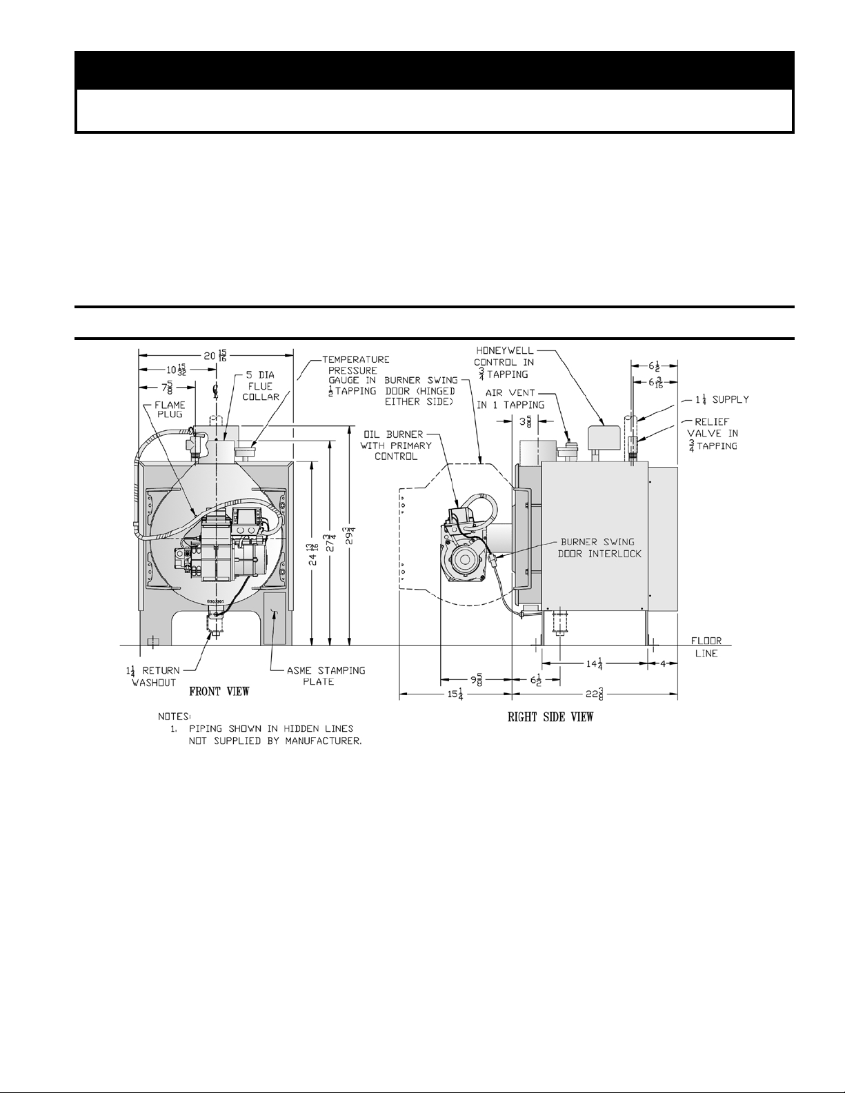
TAbLE OF CONTENTS
TNATROPMI
nisnoitcurtsnipeeK.ylluferacsnoitcurtsniesehtdaer,reliobliosihtllatsniotgnitratserofeB
.naicinhcetecivresdnarenwoybecnereferrofrelioblioraendetsopdnanoitidnocelbigel
I. General Information .................................. 3
II. Installation Instructions ............................
III. Operating and Service Instructions ..........
12
I. General Information
IV. Boiler Cleaning ........................................ 20
5
V. Repair Parts .............................................
21
VI. Appendix
Low Water Cut Off ................................... 27
Figure 1: LE™ Packaged Boiler
1. INSPECT SHIPMENT carefully for any signs of
damage.
A. ALL EQUIPMENT is carefully manufactured,
inspected and packed. Our responsibility ceases
upon delivery of crated Boiler to the carrier in good
condition.
B. ANY CLAIMS for damage or shortage in shipment
must be led immediately against the carrier by the
consignee. No claims for variances from, or
shortage in orders, will be allowed by the manufacturer unless presented within sixty (60) days after
receipt of goods.
Approximate shipping weight: 325 pounds
Water content: 6.1 gallons
Water Content: 6.1 Gallons
2. LOCATE BOILER in front of nal position before
removing crate. See Figure 1.
A. LOCATE so that smoke pipe connection to chimney
will be short and direct. BOILER IS SUITABLE
FOR INSTALLATION ON COMBUSTIBLE
FLOOR. Boiler can not be installed on carpeting.
B. FOR BASEMENT INSTALLATION, provide a
solid base, such as concrete, if oor is not level or
if water may be encountered on oor around Boiler.
C. PROVIDE SERVICE CLEARANCE of at least 24”
clearance in front for servicing.
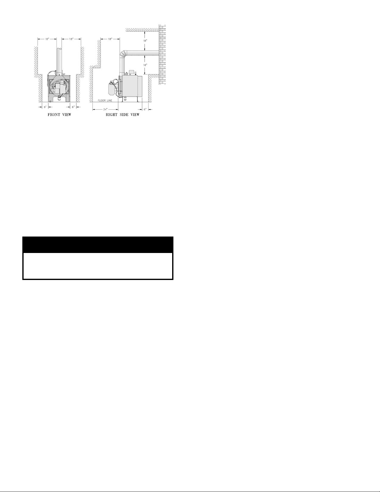
D. For minimum clearances to combustible materials
See Figure 2.
3
Page 4
GNINRAW
rianoitalitnevdnanoitsubmocetauqedA
reporperussaotdedivorpebtsum
.noitsubmoc
Figure 2: Minimum Installation Clearances To
naciremAhtiwylpmocsecnaraelcdetsiL:1ETON
liofonoitallatsnI,13APFN/ISNAdradnatSlanoitaN
.tnempiuqegninrub
smoornidellatsniebnacsreliobseireSEL:2ETON
detsilsalairetamelbitsubmocmorfsecnaraelchtiw
rofdecuderebtonnacsecnaraelcdetsiL.evoba
.snoitallatsnitesolcroevocla
elbitsubmocotsecnaraelcdecuderroF:3ETON
nidebircsedsadedivorpebtsumnoitcetorp,lairetam
.dradnats13APFN/ISNAevobaeht
Combustible Materials
3. PROVIDE COMBUSTION AND VENTILATION
AIR. Local code provisions may apply and should be
referenced.
A. Determine volume of space (boiler room). Rooms
communicating directly with the space in which the
appliances are installed, through openings not
furnished with doors, are considered a part of the
space.
Volume(ft3) = Length(ft) x Width(ft) x Height(ft)
B. Determine total input of all appliances in the space.
Add inputs of all appliances in the space and round
the result to the nearest 1000 BTU per hour.
C. Determine type of space. Divide Volume by total
input of all appliances in space. If the result is
greater than or equal to 50 ft3/1000 BTU per hour,
then it is considered an unconned space. If the
result is less than 50 ft3/1000 BTU per hour then the
space is considered a conned space.
D. For boiler located in an unconned space of a
conventionally constructed building, the fresh air
inltration through cracks around windows and
doors normally provides adequate air for combustion and ventilation.
E. For boiler located in a conned space or an uncon-
ned space in a building of unusually tight con-
struction, provide outdoor air with the use of two
permanent openings which communicate directly or
by duct with the outdoors or spaces (crawl or attic)
freely communicating with the outdoors. Locate
one opening within 12 inches of top of space.
Locate remaining opening within 12 inches of
bottom of space. Minimum dimension of air
opening is 3 inches. Size each opening per
following:
Direct communication with outdoors.
(1)
Minimum free area of 1 square inch per 4,000
BTU per hour input of all equipment in space.
(2) Vertical ducts. Minimum free area of 1 square
inch per 4,000 BTU per hour input of all
equipment in space. Duct cross-sectional area
shall be same as opening free area.
(3) Horizontal ducts. Minimum free area of 1
square inch per 2,000 BTU per hour input of all
equipment in space. Duct cross-sectional area
shall be same as opening free area.
Alternate method for boiler located within
conned space. Use indoor air if two permanent openings communicate directly with
additional space(s) of sufcient volume such
that combined volume of all spaces meet
criteria for unconned space. Size each
opening for minimum free area of 1 square
inch per 1,000 BTU per hour input of all
equipment in spaces, but not less than 100
square inches.
F. Louvers and Grilles of Ventilation Ducts
(1) All outside openings should be screened and
louvered. Screens used should not be smaller
than 1/4 inch mesh. Louvers will prevent the
entrance of rain and snow.
(2) Free area requirements need to consider the
blocking effect of louvers, grilles, or screens
protecting the openings. If the free area of the
louver or grille is not known, assume wood
louvers have 20-25 percent free area and metal
louvers and grilles have 60-75 percent free
area.
4
Page 5
II. Installation Instructions
1. REMOVE CRATE
A. Remove all fasteners at crate skid.
B. Lift outside container and remove all other inside
protective spacers and bracing. Remove container
containing Safety Relief Valve, Boiler Drain Valve
and Pipe Fittings.
2. REMOVAL OF BOILER FROM SKID
A. Tilt boiler, "walk" boiler backward, and set rear legs
down on oor. Tilt boiler backward, pull skid
forward and set front legs down on edge of skid.
Install close coupling, tee, and plug in return
coupling, see Step 7 and Figure 1. Point tee toward
permanent return location.
B. Tilt boiler backward and remove skid. Be careful not
to damage Burner and Jacket.
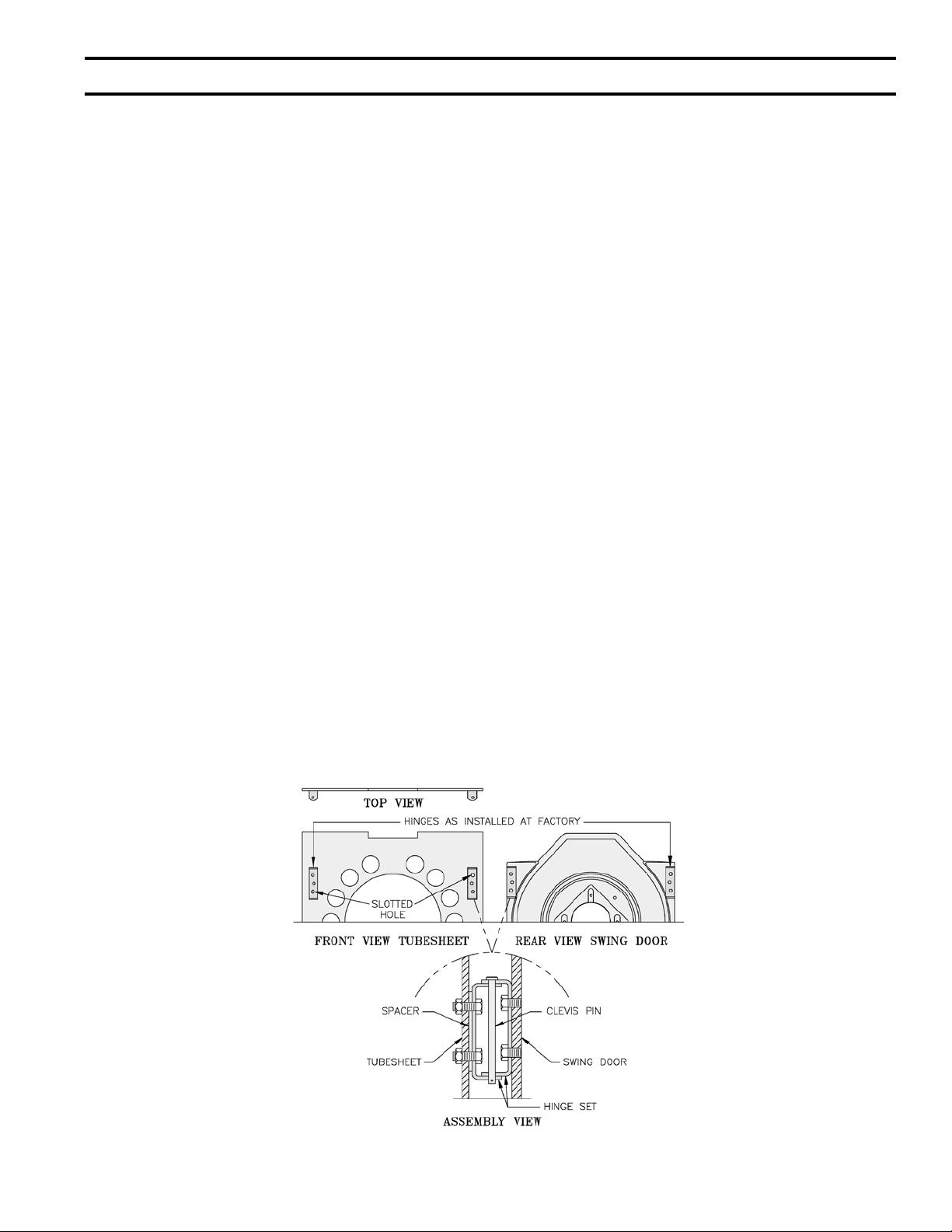
3. CHANGE HINGE POSITION if necessary.
A. Look at the area where boiler will be installed. If
left side of boiler will be less than 12 inches from a
wall, move hinges to right side of boiler. See B
through I below.
B. Pull 2 halves of Burner Swing Door Interlock apart.
Swing Door Interlock is connected to T-T terminals
on R7184A Control. Lift Honeywell R7184A
Control off of Burner Junction Box, open Burner
Ignition Transformer and disconnect wiring harness
from left side of burner. Find round plastic cover
inside Junction Box and install in hole in left side
of burner.
C. Remove 8 sheet metal screws from jacket. Remove
rear jacket box and bend both sides of Jacket
Wrapper up, see Figure 19.
D. Remove 2 (two) 5/16" - 18 x 3" long hex head cap
screws and atwashers from right side of door.
Remove 2 hairpin cotter pins and 2 hinge pins from
hinges on left side of door and remove Door
Assembly from boiler. Inspect Front and Rear
Door Insulation Pieces and Combustion Chamber
Liner, see Step 6.
E. Remove 4 hex nuts from bolts that attach hinges and
hinge spacers to left side of Tubesheet. Remove 4
hex head cap screws that attach hinges to door.
F. Attach 2 hinge brackets & spacers to Tubesheet and
2 hinge brackets to Door on right side of boiler. 3
Holes in each Hinge Bracket must line up with 3
matching holes in Spacer, Tubesheet or Door. See
Figure 3. Tighten hex nuts, bolts and screws by
hand only.
G. Replace door assembly. Hinge brackets attached to
door must rest on top of hinge brackets attached to
tubesheet. See Figure 3. Slide hinge pins through
hinges from top and install cotter pins. Close door
and install 5/16" - 18 x 3" long hex head cap screws
through atwashers and left side of door and into
tapped holes in tubesheet. Tighten all hex nuts,
bolts and screws. When door is installed properly,
it is parallel to Tubesheet when viewed from top
and sides.
H. Bend sides of Jacket Wrapper down and attach 2
Jacket Straps to 4 slots at bottom of Jacket Wrapper
sides with sheet metal screws. Install Rear Jacket
Box with 4 sheet metal screws. See Figure 19.
I. Connect wiring harness to a knockout on right side
of Junction Box and install Honeywell R7184A
Control, see Wiring Diagram, Figures 11A and 11B.
Reconnect Swing Door Interlock.
Figure 3: Hinge Installation & Assembly, LE Boiler
5
Page 6
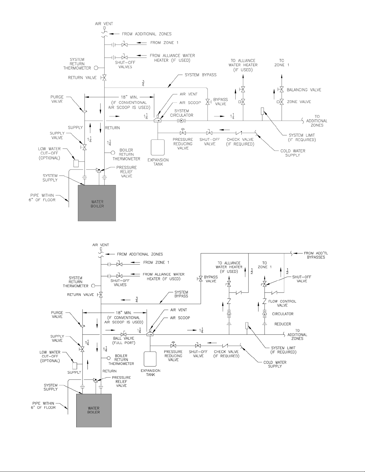
Figure 4: Recommended Water Piping for Zone Valve Zoned Heating Systems
Figure 5: Recommended Water Piping for Circulator Zoned Heating Systems
6
Page 7
NOITUAC
lliwretawreliobfonoitanimatnocnegyxO
reliobleetsdnanorifonoisorrocesuac
.eruliafreliobotdaelnacdna,stnenopmoc
tonseodytnarrawdradnatss'mahnruB
negyxoybdesuacsmelborprevoc
.retawreliobfonoitanimatnoc
4. INSTALL BOILER CONTROL.
A. Pull bulb and capillary tube out of hole in back of
control. Insert bulb in immersion well on top of
boiler and secure control with set screw in control.
B. Secure exible conduit to Jacket Wrapper side with
conduit clamp and sheet metal screw. Conduit must
be on same side of boiler as Swing Door hinges.
5. MOVE BOILER TO PERMANENT POSITION by
sliding or walking.
6. INSPECT FRONT AND REAR DOOR INSULATION
PIECES AND COMBUSTION CHAMBER LINER
A. OPEN SWING DOOR on front of boiler. Use
ashlight to inspect insulation pieces secured to
front and rear doors. Inspect Ceramic Fiber Blanket
secured to bottom of combustion chamber with
water glass adhesive. Replace any damaged pieces.
7. CONNECT SUPPLY AND RETURN PIPING TO
HEATING SYSTEM
A. Hot water pipes shall have clearances of at least ½”
from all combustible construction.
B. Use a system by-pass if the boiler is to be operated
in a system which has a large volume or excessive
radiation where low boiler water temperatures may
be encountered (i.e. converted gravity circulation
system, etc.).
Valves should be located in the by-pass and return
line as illustrated in Figures 4 and 5 in order to
regulate water ow for maintenance of higher
boiler water temperature.
Set the by-pass and return valves to a half throttle
position to start. Operate boiler until the system
water temperature reaches its normal operating
range.
Adjust the valves to maintain 180°F to 200°F boiler
water temperature and greater than 120°F return
temperature. Adjust both valves simultaneously.
Closing the boiler return valve while opening the
by-pass valve will raise the boiler return tempera-
ture. Opening the boiler return valve while closing
the by-pass valve will lower the boiler return
temperature.
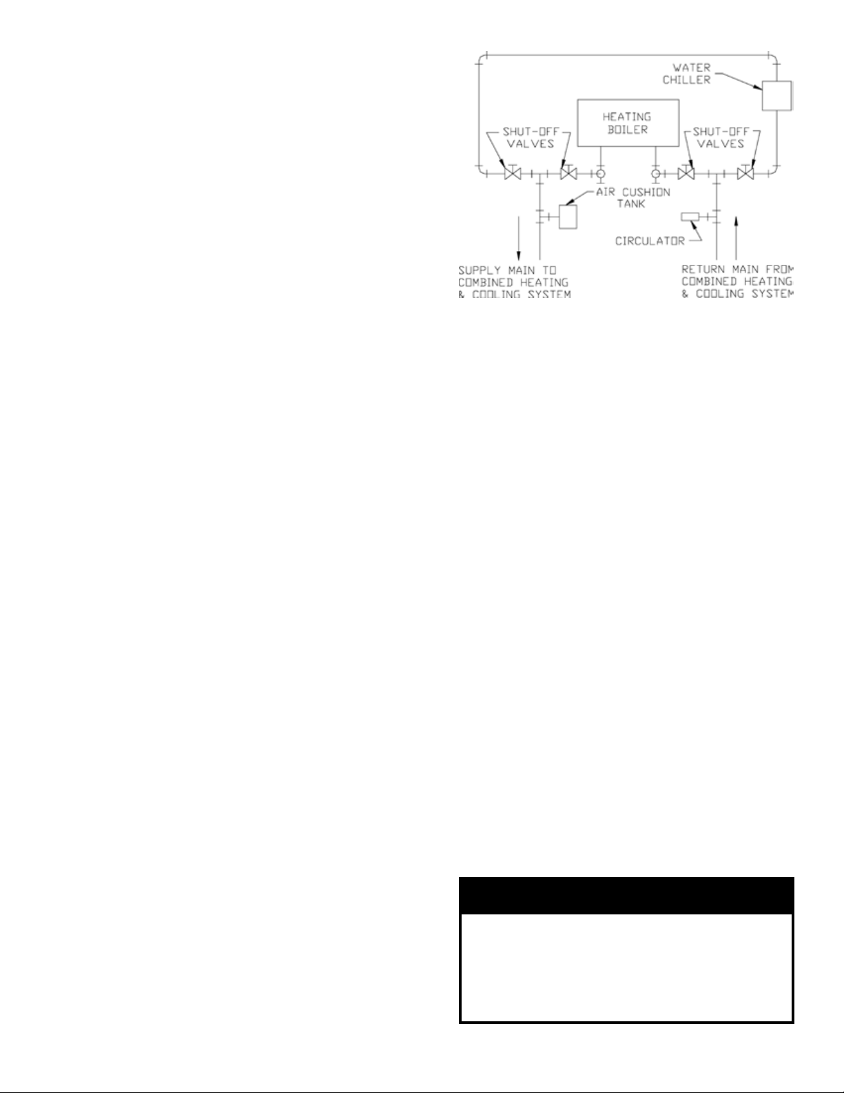
C. If this boiler is used in connection with refrigeration
systems, the boiler must be installed so that the
chilled medium is piped in parallel with the heating
boiler using appropriate valves to prevent the
chilled medium from entering the boiler, see Figure
6. Also consult I=B=R Installation and Piping
Guides.
D. If this boiler is connected to heating coils located in
air handling units where they may be exposed to
refrigerated air the boiler piping must be equipped
with ow control valves to prevent gravity circula-
tion of boiler water during the operation of the
cooling system.
Figure 6: Recommended Piping for
Combination Heating & Cooling
(Refrigeration) Systems
E. A hot water boiler installed above radiation level
must be provided with a low water cutoff device as
part of the installation.
If a low water cut-off is required, it must be mount-
ed in the system piping above the boiler.
The minimum safe water level of a hot water boiler
is just above the highest water containing cavity of
the boiler; that is, a hot water boiler must be full of
water to operate safely.
F. There are many possible causes of oxygen contami-
nation such as:
(1) Addition of excessive make-up water as a
result of system leaks.
(2) Absorption through open tanks and ttings.
(3) Oxygen permeable materials in the distribution
system.
In order to insure long product life, oxygen sources
should be eliminated. This can be accomplished by
taking the following measures:
(1) Repairing system leaks to eliminate the need
for addition of make-up water.
(2) Eliminating open tanks from the system.
(3) Eliminating and/or repairing ttings which
allow oxygen absorption.
(4) Use of non-permeable materials in the distribu-
tion system.
(5) Isolating the boiler from the system water by
installing a heat exchanger.
7
Page 8
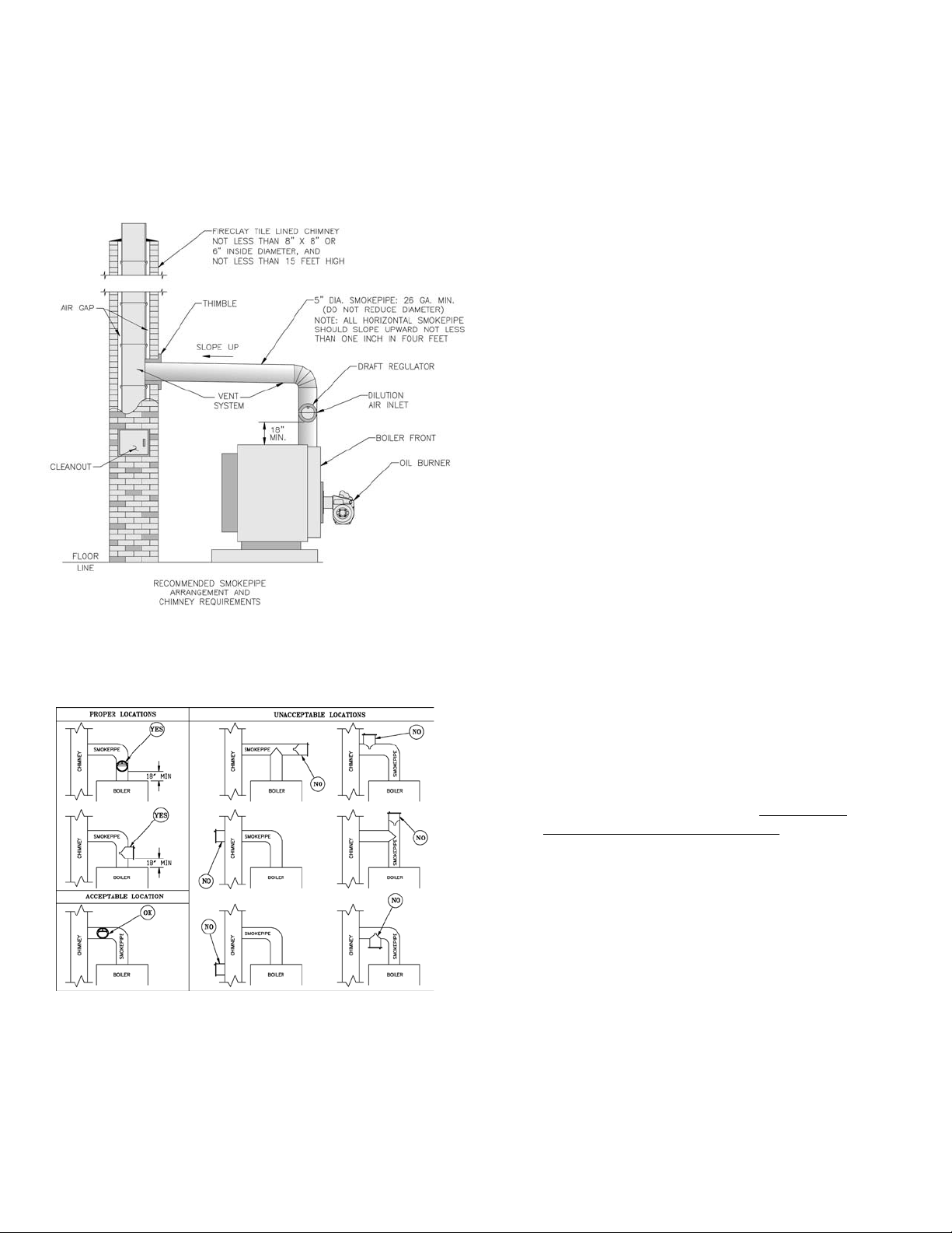
8. INSTALL SMOKEPIPE — The LE should be vented
into a reclay tile-lined masonry chimney or a chimney
constructed from Type L Vent or a factory built
chimney that complies with the Type HT requirement,
of UL103. The chimney and vent pipe shall have a
sufcient draft at all times, to assure safe proper
operation of the boiler. See Figure 7 for recommended
installation.
a home without insulation or storm windows. With
increasing fuel prices that home probably has been
insulated and tted with storm windows so that the
heat loss of the home has been reduced. This
requires less fuel to be burned and sends less heat
up the chimney.
A new boiler probably has a higher efciency than
the boiler being replaced. That probably means that
the stack temperature from the new boiler will be
lower than that from the old boiler and with less
room air being drawn up the chimney to dilute the
stack gases. The combination of a large uninsulated
chimney, reduced ring rate, reduced ring time,
lower stack temperature and less dilution air can, in
some cases, contribute to the condensing of small
amounts of water vapor in the chimney. Such
condensation, when it occurs, can cause chimney
deterioration. In extreme cases, condensed water
may be visible on the outside of the breeching or
chimney. In those extreme cases, the chimney may
have to be lined to insulate the chimney and thus
prevent the condensation. The addition of dilution
air into the chimney may assist in drying the
chimney interior surfaces.
C. Heat extractors mounted into the breeching are not
recommended.
Figure 7
A. Install the draft regulator following the instructions
furnished with the regulator. See Figure 8 for
alternate draft regulator locations.
Figure 8
B. Consider the chimney overall. Chimneys that have a
high heat loss may become less suitable as the heat
loss of the home goes down and the efciency of
the boiler installed goes up. Most homes have a
chimney appropriate for the fuel and the era in
which the home was built. That may have been a
coal red or an inefcient oil red boiler built into
9. INSTALL ELECTRIC WIRING
A. Follow the National Electrical Code and local
regulations. A separate electrical circuit must be run
from the main electrical service with an overcurrent device/disconnect in the circuit. A service
switch is recommended and may be required by
some local jurisdictions. Wiring should conform to
Figures 11A, 11B and 11C.
B. CANADA — Refer to CSA standard C22.2 Part 1,
1990, Electrical Features of Fuel Burning Equipment (Gas and Oil).
C. If boiler is installed in Canada, a blocked vent safety
switch must be installed. Refer to Blocked Vent
Safety Switch Instruction Supplement provided
with boiler (Canada only).
10. FUEL UNITS AND OIL LINES
Use exible oil line(s) so that Swing Door can be
opened without disconnecting oil supply.
A supply line fuel oil lter is recommended as a
minimum for all ring rates but a pleated paper fuel oil
lter is recommended for the lowest (.6 GPH) ring
rate application to prevent nozzle fouling.
SINGLE-PIPE OIL LINES — Standard burners are
provided with single-stage 3450 rpm fuel units with the
by-pass plug removed for single-pipe installations.
The single-stage fuel unit may be installed single-pipe
with gravity feed or lift. Maximum allowable lift is 8
feet. See Figure 9.
8
Page 9
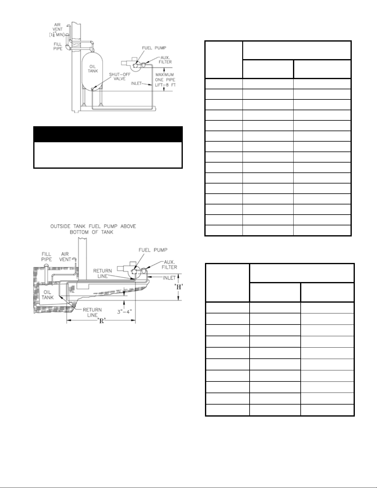
:2ELBAT )MPR0543(STINUEGATS-ELGNIS
SMETSYSEPIP-OWT
"H"tfiL
gnibuTfohtgneLmumixaM
"R"+"H"
DO"8/3
)HPG3(gnibuT
DO"2/1
)HPG3(gnibuT
'0 '48 '001
'1 '87 '001
'2 '37 '001
'3 '86 '001
'4 '36 '001
'5 '75 '001
'6 '25 '001
'7 '74 '001
'8 '24 '001
'9 '63 '001
'01 '13 '001
'11 '62 '001
'21 '12 '38
'31 --- '26
'41 --- '14
:3ELBAT )MPR0543(STINUEGATS-OWT
SMETYSEPIP-OWT
"H"tfiL
gnibuTfohtgneLmumixaM
"R"+"H"
DO"8/3
)HPG3(gnibuT
DO"2/1
)HPG3(gnibuT
'0 '39 '001
'2 '58 '001
'4 '77 '001
'6 '96 '001
'8 '06 '001
'01 '25 '001
'21 '44 '001
'41 '63 '001
'61 '72 '001
'81 --- '67
Figure 9
TNATROPMI
yletulosbaebtsumsnoitallatsniepip-elgniS
.tluseryamemirpfossolroskaelrothgitria
.yletelpmoctinuleufdnaenildeelB
TWO-PIPE OIL LINES - For two-pipe systems where
more lift is required, the two-stage fuel unit is
recommended. Tables 2 (single-stage) and 3 (two-stage)
show allowable lift and lengths of 3/8-inch and ½-inch
OD tubing for both suction and return lines. Refer to
Figure 10.
Be sure that all oil line connections are absolutely
airtight.
Check all connections and joints. Flared ttings are
recommended. Do not use compression ttings.
Open the air-bleed valve and start the burner. For clean
bleed, slip a 3/16” ID hose over the end of the bleed
valve and bleed into a container. Continue to bleed for
15 seconds after oil is free of air bubbles. Stop burner
and close valve.
Figure 10
9
Page 10

Figure 11A: Wiring Diagram for LE Boilers with Beckett AFG Burner and Split Controls
SEQUENCE OF OPERATION
A call for heat by the thermostat energizes the L7248C control which in turn energizes the R7184B primary control. The burner
will initiate ignition after completing a 10 second pre-purge cycle. If burner ignites within approximately 45 seconds and the cad
cell sees ame, the burner will continue to operate until the call for heat is satised or the setting of the high limit is reached. The
circulator will operate as long as the thermostat is calling for heat. If the thermostat is not satised and the high limit is reached, the
circulator will continue to operate, and the burner will stop until the high limit is closed by a drop in boiler water temperature.
Figure 11B: Wiring Diagram for LE Boilers with Beckett AFG Burner, EC5000 Control,
and Honeywell L4080B High Limit
SEQUENCE OF OPERATION
Refer to EC5000 Manual for wiring and operation details.
10
Page 11

Figure 11C: Wiring Diagram for LE Boilers with Riello Burner
11
Page 12

III. Operating and Service Instructions
GNINRAW
erevesesuacnachcihwdrazahlaitnetopaevahroodgniwsrenrubhtiwdeppiuqesreliobllA
ffonrut,roodgniwsgninepoerofeB.derongifiefilfossolroyrujnilanosrep,egamadytreporp
gniriwkcolretnIrooDgniwSrenruBfosevlahowttcennocsiddnareliobothctiwsecivres
oteruseB.rebmahcnoitsubmocehtedistuorenrubfogniriflatnediccatneverpotssenrah
rooDgniwSrenruBfosevlahowttcennocerdnayletelpmocrenetsafroodgniwsnethgit
.detelpmocsiecivresnehwkcolretnI
1. ALWAYS INSPECT INSTALLATION BEFORE
STARTING BURNER.
2. FILL HEATING SYSTEM WITH WATER.
NOTE: It is important to properly remove the oil and
dirt from the system.
CLEAN HEATING SYSTEM If boiler water is dirty,
refer to step 13 for proper cleaning instructions.
A. Fill entire Heating System with water and vent air
from system. Use the following procedure on a
Series Loop or Multi-Zoned System installed as per
Figures 4 and 5, to remove air from system when
lling:
(1) Close isolation valve in boiler supply piping.
(2) Isolate all circuits by closing zone valves or
balancing valves.
(3) Attach a hose to hose bib located just below
isolation valve in boiler supply piping.
(Note - Terminate hose in ve gallon bucket at a
suitable oor drain or outdoor area).
(4) Starting with one circuit, open zone valve.
(5) Open hose bib.
(6) Open ll valve (Make-up water line should be
located directly above isolation valve in boiler
supply piping).
(7) Allow water to overow from bucket until dis
charge from hose is bubble free for 30 seconds.
(8) Open zone valve to the second zone to be
purged, then close the rst. Repeat this step
until all zones have been purged, but always
have one zone open. At completion, open all
zone valves.
(9) Close hose bib, continue lling the system until
the pressure gauge reads 12 psi. Close ll
valve.
(Note - If make-up water line is equipped with
pressure reducing valve, system will automati-
cally ll to 12 psi. Leave globe valve open).
(10) Open isolation valve in boiler supply piping.
(11) Remove hose from hose bib.
3. CHECK CONTROLS, WIRING AND BURNER to be
sure that all connections are tight and burner is rigid,
12
that all electrical connections have been completed and
fuses installed, and that oil tank is lled and oil lines
have been tested.
4. LUBRICATION — Follow instruction on burner and
circulator label to lubricate, if oil lubricated. Most
motors currently used on residential type burners
employ permanently lubricated bearings and thus do
not require any eld lubrication. Water lubricated
circulators do not need eld lubrication.
Do not over-lubricate. This can cause as much trouble as no
lubrication at all.
5. ADJUST CONTROLS SETTINGS with burner service
switch turned “ON”.
A. SET ROOM THERMOSTAT about 10° above
room temperature.
B. PRESS RED RESET BUTTON.
C. On WATER BOILERS WITHOUT TANKLESS
HEATERS equipped with L7248 electronic
aquastat controller, set High Limit (HL) at 180°F.
This temperature can be varied to suit installation
requirements. L7248 controller has the High Limit
adjustment range from 180°F to 240°F (82°C to
116°C). High Limit Differential is xed at 15°F
(8°C).
D. ADJUSTING AQUASTAT CONTROLLER
SETTINGS. To discourage unauthorized changing
of Aquastat settings, a procedure to enter the
ADJUSTMENT mode is required. To enter the
ADJUSTMENT mode, press the UP, DOWN, and
I buttons (refer to Figure 12) simultaneously for
three seconds. Press the I button until the feature
requiring adjustment is displayed:
• HL_ High Limit.
• °F °C.
Then, press the UP and/or DOWN buttons to move
the set point to the desired value. After 60 seconds
without any button inputs, the control will auto-
matically return to the RUN mode.
L7248 Aquastat Controller will not display Low
Limit and Low Limit Differential adjustment
features.
Page 13

setting and has not gone below the Low Limit
setting (minus the Differential).
(2) High Limit: Boiler temperature went above the
High Limit setting and has not dropped below
the High Limit setting (minus the Differential).
TABLE 4: LED ERROR CODES
Figure 12: L7248 Circuit Board Layout -
Horizontal Mount
E. DISPLAY READOUT
In the
RUN mode, the Aquastat will ash "bt"
(boiler temp) followed by the temperature (i.e.,
220), followed by °F or °C.
To read boiler settings, press the I key to read the
parameter of interest. For example, press I High
Limit (HL) is displayed, followed by a three-digit
number, i.e., 220, followed by °F or °C. See
Display Readout, Figure 13.
Figure 13: Display Readout Denitions
After approximately 60 seconds without any key
presses, the display will enter a dim display mode.
To return to the bright display mode, simply press
any key.
F. OPERATION
The L7248 model is restricted to three operational
states - Normal, High Limit and Error. The
controller moves back and forth from High Limit to
Normal state as part of normal operation.
The controller will enter the Error state when there
is an abnormal condition. The operating states are:
(1) Normal: Boiler temperature went below the
High Limit setting (minus the Differential) and
has not exceeded the High Limit setting; or the
boiler temperature went above the Low Limit
Error
Code
Err1 Sensor fault; check sensor.
Err2 ECOM fault; check EnviraCOM™ wiring.
Err3 Hardware fault; replace control.
Err4 B1 fault; check B1 wiring/voltage.
Err5 Low Line; check L1-L2, 110 Vac.
Err6 Fuse; check ECOM wires, replace fuse.
Err7
Err8
EEPROM, HL, Hdf; reset to default values.
Repeated B1 fault (voltage present at B1 when
output is turned off); check B1 wiring/voltage.
Cause / Action
Restore desired settings.
(3) Error: The controller has detected an error
condition (e.g., open sensor) and has shut down
TABLE 5: L7248 CONTROLLER OPERATING
SEQUENCE
Action System Response
Thermostat
calls for heat.
Boiler
exceeds the
High Limit.
Thermostat is
satised.
Error
condition 1-5.
Error
condition 6.
Error
condition 7.
Error
condition 8.
Circulator starts when water temperature
is above Low Limit setting (if applicable).
Boiler temperature is checked. Burner
starts when water temperature is below
High Limit setting.
Burner is turned off. Burner restarts when
the water temperature drops below the
High Limit setting minus the Differential.
Circulator and burner turn off.
If an error condition is detected, all outputs
except ZC are shut down. Burner is off.
Control continues to function and restarts
when error is corrected.
During the error check sequence, the
system checks for drift in the sensor and
corrosion in the connections.
EnviraCOM communication is not
available.
The control has reset the High Limit
setting to a default setting and will
continue to run at those settings.
Performance of the system will be
degraded.
If the error condition is detected, all
outputs except ZC are shut down. Burner
is off. Control continues to function and
restarts when all three user keys have
been pressed longer than 60 seconds.
13
Page 14
the burner output. The ZC output is energized.
The controller continues to monitor the system
and automatically restarts if the error condition
clears. Refer to Table 4.
The operating sequence for the L7248 is shown in
Table 5.
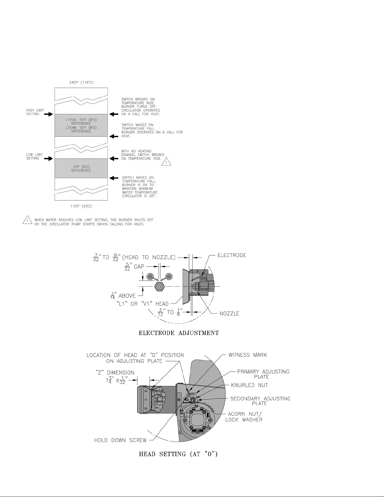
G. HIGH LIMIT CONTROLLER
The High Limit opens and turns off the burner when
the water temperature reaches the setpoint. The
High Limit automatically resets after the water
temperature drops past the setpoint and through the
Differential. The L7248 models have High Limit
Differential presets of 15°F (8°C). See Figure 14.
6. REMOVE GUN ASSEMBLY
LE Boilers equipped with Beckett AFG burners. Items
to be checked are nozzle size, type, and angle; head
size, (and setting on MD(V1) head); gun setting; and
positioning of electrodes. This information is shown in
Figure 15, and Table 6. If the desired boiler ring rate
is 0.6 GPH, the nozzle must be changed out, the low
ring rate bafe must be installed and the factory
settings must be changed according to Table 6. These
parts are in the bag attached to the burner. Reinstall
gun assembly.
LE Boilers equipped with Riello 40 F3 and 40 F5
burners: Items to be checked are nozzle size, type and
angle: settings (air gate, turbulator and pump pressure).
This information is shown in Table 6A. Reinstall gun
assembly.
Figure 14: Setpoints and Differentials
7. ADJUST OIL BURNER BEFORE STARTING
A. SET BURNER SETTINGS, see Tables 6 and 6A.
B. OPEN ALL OIL LINE VALVES.
14
Figure 15: "L1" and "V1" Head Electrode Positioning and Gun Setting (Beckett AFG)
Page 15

TABLE 6: BECKETT AFG BURNER
Boiler
Model
LE1 0.60 *
LE2 1.00 0.85 60° B 10 0 N/A 140
LE3 1.25 + MD(V1) 2-3/4U Delavan 1.10 45° B 10 1.5 0 140
Firing
Rate
Head
(GPH)
MB(L1) 3-3/8U
Settings are approximate and must be veried by Smoke and Carbon Dioxide measurement. Readjust where necessary.
See Text of the Manual.
* Install low ring rate bafe for 0.60 GPH ring rate.
+ Do not change the ring rate of the 1.25 GPH burner.
Static
Disc
Manufacturer GPH Angle Type
Hago or
Delavan
Nozzle Settings
Air
Shutter
0.50 70° B 5 0 N/A 140
Air
Band
Head
TABLE 6A: RIELLO BURNER SPECIFICATIONS
Boiler
Model
LE1 0.60 F3 Delavan 0.50 x 60°A 2.8
LE2 1.00 F5 Delavan 0.85 x 60°A 3.0 1.0
LE3 1.25 F5 Delavan 1.00 x 60°A 3.5 3.0
C. Attach a plastic hose to fuel pump vent tting and
D. REMOVE GAUGE PORT PLUG from fuel pump
E. REMOVE FLAME PLUG IN SWING DOOR.
8. START OIL BURNER
A. Open vent tting on fuel pump.
B. TURN ‘ON’ BURNER service switch and allow
C. Close vent tting and burner ame should start
9. ADJUST OIL PRESSURE
A. Locate oil pressure adjusting screw and turn screw
B. DO NOT REMOVE PRESSURE GAUGE until
10. OTHER ADJUSTMENTS
A. ADJUST THE AIR BAND AND/OR AIR SHUT-
Beckett Burners:
Adjust air supply by loosening lock screws and
Firing Rate
(GPH)
Burner
Model
Nozzle
provide a pan to catch the oil.
and install pressure gauge.
burner to run until oil ows from vent tting in a
SOLID stream without air bubbles for approximately 10 seconds.
immediately after pre-purge is complete. Pre-purge
prevents burner ame until 10 seconds has elapsed
after initial power is applied to burner. During prepurge, the motor and ignitor will operate but the oil
valve will remain closed. Refer to Oil Primary
Control Instructions for more details.
to obtain the oil pressure indicated in Tables 6 and
6A.
later.
TER
moving the air shutter and if necessary the air band.
Refer to Table 6 for preliminary settings.
Air Gate Pump Pressure Turbulator
B. ADJUST DRAFT REGULATOR for a draft of 0 to
maximum of -.03" (water gauge) in the breeching
after chimney has reached operating temperature
and while burner is running. Burner will operate
with a positive draft over re and zero draft in the
breeching. Adjust Draft Regulator such that
maximum draft of -.03" is reached in coldest
weather.
C. READJUST AIR BANDS on burner for a light
orange colored ame. Use a smoke tester and adjust
air for minimum smoke (not to exceed #1) with a
minimum of excess air. Make nal check using
suitable instrumentation to obtain a CO2 of 11.5 to
12.5%. These settings will assure a safe and
efcient operating condition. If the ame appears
stringy instead of a solid re, try another nozzle of
the same type. Flame should be solid and compact.
After all adjustments are made recheck for a draft
of zero to -.03" (water gauge) in breeching.
D. TURN “OFF” BURNER and remove pressure
gauge. Install gauge port plug and tighten. Start
burner again.
E. CAD CELL LOCATION AND SERVICE
The burner is supplied with a cadmium sulde ame
detector mounted at the factory, mounted on the
bottom of the transformer. See Figure 16. To
service cad cell or to replace the plug in portion,
swing open the transformer. After service is
complete, be sure to fasten down the transformer.
F. FLAME FAILURE
The LE boiler controls operate the burner automati
cally. If for unknown reasons the burner ceases to
re and the reset button on the primary control has
tripped, the burner has experienced ignition failure.
Settings
145
Pump
Pressure
(PSIG)
0.5
-
15
Page 16

Figure 16: Cad Cell
NOITUAC
nehwrenrubehttratsottpmettatonoD
tinuehtnehw,detalumuccasahliossecxe
noitsubmocehtnehwro,ropavfollufsi
.tohyrevsirebmahc
GNINRAW
sireliobehtfonoitallatsnierofeB
ehtfonoitarepoeht,etelpmocderedisnoc
,dekcehcebdluohsslortnocreliob
hgihdnalortnocyramirpehtylralucitrap
.lortnoctimil
NOITUAC
YLNONAMECIVRESGNITAEHROF
Before pressing the reset button call your serviceman immediately.
11. CHECK FOR CLEAN CUT OFF OF BURNER
A. AIR IN THE OIL LINE between fuel unit and
nozzle will compress when burner is on and will
expand when burner stops, causing oil to squirt
from nozzle at low pressure as burner slows down
and causing nozzle to drip after burner stops.
Usually cycling the burner operation about 5 to 10
times will rid oil line of this air.
B. IF NOZZLE CONTINUES TO DRIP, repeat step
(11A). If this does not stop the dripping, remove
cutoff valve and seat, and wipe both with a clean
cloth until clean, then replace and re-adjust oil
pressure.
12. TEST CONTROLS.
(1) Safe Start
i. Jumper the yellow cad cell leads.
ii. Follow procedure to turn on burner.
Burner must not start, indictor light turns
on and control remains in Idle Mode.
(2) Simulate Flame Failure.
i. Follow procedure to turn on burner.
ii. Close hand valve in oil supply line.
iii. Device enters recycle mode.
iv. Device tries to restart system after
approximately 60 seconds.
v. Safety switch locks out approximately in
safety switch timing indicated on label.
Indicator light ashes at 1 Hz rate.
Ignition and motor stop and oil valve
closes.
(3) Simulate Ignition Failure.
i. Follow procedure to turn on burner, but do
not open oil supply hand valve.
ii. Observe that safety switch locks out
approximately within safety switch timing
as indicated on the label. Indicator light
ashes at 1 Hz rate. Ignition and motor
stop and oil valve closes.
(4) The indicator light on the oil primary control
provides lockout, recycle and cad cell indications as follows:
i. Flashing at 1 Hz (½ second on, ½ second
off): system is locked out or in restricted
mode.
ii. Flashing at ¼ Hz (2 seconds on, 2 seconds
off): control is in recycle mode.
iii. On: cad cell is sensing ame.
iv. Off: cad cell is not sensing ame.
C. CHECK HIGH LIMIT CONTROL. Jumper
thermostat terminals. Allow burner to operate until
shut-down by limit. Installation is not considered
complete until this check has been made.
REMOVE JUMPER.
IF CONTROLS DO NOT MEET REQUIREMENTS
OUTLINED IN PARAGRAPH 12, REPLACE
CONTROL AND REPEAT CHECK-OUT
PROCEDURES.
A. CHECK THERMOSTAT OPERATION. Raise and
lower thermostat setting as required to start and
stop burner.
B. VERIFY PRIMARY CONTROL SAFETY FEA-
TURES using procedures outlined in instructions
furnished with control or instructions below:
16
13. BOILER AND SYSTEM CLEANING INSTRUC-
TIONS FOR TROUBLE FREE OPERATION
A. Filling of Boiler and System — General —-In a hot
water heating system, the boiler and entire system
(other than the expansion tank) must be full of
water for satisfactory operation. Water should be
added to the system until the boiler pressure gauge
registers 12 psi. To insure that the system is full,
water should come out of all air vents when
opened. The LE boiler holds 6.1 gallons of water.
Page 17

B. Boiling Out of Boiler and System. The oil and grease
TNATROPMI
SITI,NOITAREPOLAMRONGNIRUD,FI
EROMRETAWDDAOTYRASSECEN
,HTNOMAECNONAHTYLTNEUQERF
ECIVRESDEIFILAUQATLUSNOC
METSYSRUOYKCEHCOTNAICINHCET
.SKAELROF
which accumulate in a new hot water boiler can be
washed out in the following manner.
(1) Remove Safety Relief Valve using extreme care
to avoid damaging it.
(2) Partially ll boiler and add caustic soda or triso-
dium phosphate. Add an appropriate amount of
recommended boil out compound.
(3) Replace Safety Relief Valve.
(4) Fill the entire system with water.
(5) Start ring the boiler.
(6) Circulate the water through the entire system.
(7) Vent the system, including the radiation.
(8) Allow boiler water to reach operating tempera-
ture, if possible.
(9) Continue to Circulate the water for a few hours.
(10) Stop ring the boiler.
(11) Drain the system in a manner and to a location
that hot water can be discharged with safety.
(12) Remove plugs from all available returns and
wash the water side of the boiler as thoroughly
as possible, using a high-pressure water stream.
(13) Rell the system with fresh water.
C. Add appropriate boiler water treatment compounds
as recommended by your qualied water treatment
company.
D. Make pH or Alkalinity Test.
After boiler and system have been cleaned and
relled as previously described, test the pH of the
water in the system. This can easily be done by
drawing a small sample of boiler water and testing
with hydrion paper which is used in the same
manner as litmus paper, except it gives specic
readings. A color chart on the side of the small
hydrion dispenser gives the reading pH. Hydrion
paper is inexpensive and obtainable from any
chemical supply house or thru your local druggist.
The pH should be higher than 7 but lower than 11.
Add appropriate water treatment chemicals, if
necessary, to bring the pH within the specied
range. With this lower level of protection, care must
be exercised to eliminate all of the free oxygen in
the system.
E. Boiler is now ready to be put into service.
A leaky system will increase the volume of make-up
water supplied to the boiler which can signicantly
shorten the life of the boiler. Entrained in make-up
water are dissolved minerals and oxygen. When the
fresh, cool make-up water is heated in the boiler the
minerals fall out as sediment and the oxygen
escapes as a gas. Both can result in reduced boiler
life. The accumulation of sediment can eventually
isolate the water from contacting the steel. When
this happens the steel in that area gets extremely hot
and eventually cracks. The presence of free oxygen
in the boiler creates a corrosive atmosphere which,
if the concentration becomes high enough, can
corrode the steel through from the inside. Since
neither of these failure types are the result of a
manufacturing defect the warranty does not apply.
Clearly it is in everyone’s best interest to prevent
this type of failure. The maintenance of system
integrity is the best method to achieve this.
14. HINTS ON COMBUSTION
A. NOZZLES — Although the nozzle is a relatively
inexpensive device, its function is critical to the
successful operation of the oil burner. The selection
of the nozzle supplied with the LE boiler is the
result of extensive testing to obtain the best ame
shape and efcient combustion. Other brands of the
same spray angle and spray pattern may be used but
may not perform at the expected level of CO2 and
smoke. Nozzles are delicate and should be protected from dirt and abuse. Nozzles are mass-produced
and can vary from sample to sample. For all of
those reasons a spare nozzle is a desirable item for
a serviceman to have.
B. FLAME SHAPE — Looking into the combustion
chamber through the ame plug hole, the ame
should appear straight with no sparklers rolling up
toward the top of the chamber. If the ame drags to
the right or left, sends sparklers upward or makes
wet spots on the rear door insulation piece, the
nozzle should be replaced. If the condition persists
look for fuel leaks, air leaks, water or dirt in the
fuel as described below.
C. FUEL LEAKS — Any fuel leak between the pump
and the nozzle will be detrimental to good combustion results. Look for wet surfaces in the air tube,
under the transformer, and around the air inlet. Any
such leaks should be repaired as they may cause
erratic burning of the fuel and in the extreme case
may become a re hazard.
D. AIR LEAKS — Any such leaks should be repaired,
as they may cause erratic burning of the fuel and in
extreme cases may become a re hazard.
There are many possible causes of air leaks in oil
lines such as:
(1) Fitting leaks due to mis-ared tubing or
damaged tting.
(2) Fuel line leak due to crushed or bent tubing.
(3) Filter connection leaks.
17
Page 18

Important Product Safety Information
Refractory Ceramic Fiber Product
Warning:
The Repair Parts list designates parts that contain refractory ceramic fibers
(RCF). RCF has been classified as a possible human carcinogen. When
exposed to temperatures about 1805°F, such as during direct flame contact,
RCF changes into crystalline silica, a known carcinogen. When disturbed as a
result of servicing or repair, these substances become airborne and, if inhaled,
may be hazardous to your health.
AVOID Breathing Fiber Particulates and Dust
Precautionary Measures:
Do not remove or replace RCF parts or attempt any service or repair work
involving RCF without wearing the following protective gear:
1. A National Institute for Occupational Safety and Health (NIOSH)
approved respirator
2. Long sleeved, loose fitting clothing
3. Gloves
4. Eye Protection
• Take steps to assure adequate ventilation.
• Wash all exposed body areas gently with soap and water after contact.
• Wash work clothes separately from other laundry and rinse washing
machine after use to avoid contaminating other clothes.
• Discard used RCF components by sealing in an airtight plastic bag. RCF
and crystalline silica are not classified as hazardous wastes in the United
States and Canada.
First Aid Procedures
:
• If contact with eyes: Flush with water for at least 15 minutes. Seek
immediate medical attention if irritation persists.
• If contact with skin: Wash affected area gently with soap and water.
Seek immediate medical attention if irritation persists.
• If breathing difficulty develops: Leave the area and move to a location
with clean fresh air. Seek immediate medical attention if breathing
difficulties persist.
• Ingestion: Do not induce vomiting. Drink plenty of water. Seek
immediate medical attention.
18
Page 19

TNATROPMI
RETNIWGNIRUDDESUTONSIRELIOBFI
OTDENIARDYLLUFEBTSUMTI,EMIT
.EGAMADEZEERFTNEVERP
(4) Tank connection leaks.
TNATROPMI
doogyrevA.ERUDECORPTSETKCEHC
otsismelborpedisleufgnitalosiroftset
'2ahtiwdnametsysleufehttcennocsid
evifyrailixuanafotuoerif,gnibutfohtgnel
morflio2#mraw,hserf,naelcfoliapnollag
snurrenrubehtfI.ecruosrehtona
ehtfotuogniwardnehwyllufsseccus
otdetalosisimelborpehtnehtliapyrailixua
ehtnodesugniebsenilleufroleufeht
.etisboj
There are various test kits available to trace air
leaks, such as electronic sight glasses. Follow the
manufacturers' instructions to nd air leaks.
The following actions can eliminate air leaks:
(1) Bleed pump as detailed previously.
(2) Replace are ttings.
(3) Replace oil supply line.
(4) Repair oil lter leaks.
(5) Replace or repair tank ttings.
H. COLD OIL — If the oil temperature approaching
the fuel pump is 40°F or lower poor combustion or
delayed ignition may result. Cold oil is harder to
atomize at the nozzle. Thus, the spray droplets get
larger and the ame shape gets longer. An outside
fuel tank that is above grade or has fuel lines in a
shallow bury is a good candidate for cold oil. The
best solution is to bury the tank and lines deep
enough to keep the oil above 40°F.
I. HIGH ALTITUDE INSTALLATIONS
Air settings must be increased at higher altitudes.
Use instruments and set for 11.5 to 12.5% CO2.
J. START-UP NOISE — Late ignition is the cause of
start-up noises. If it occurs recheck for electrode
settings, ame shape, air or water in the fuel lines.
K. SHUT DOWN NOISE — If the ame runs out of air
before it runs out of fuel, an after burn with noise
may occur. That may be the result of a faulty cut-
off valve in the fuel pump, or it may be air trapped
in the nozzle line. It may take several ring cycles
for that air to be fully vented through the nozzle.
Water in the fuel or poor ame shape can also cause
shut down noises.
E. GASKET LEAKS — If 11.5 to 12.5% CO2 with a
#1 smoke or less cannot be obtained in the
breeching, look for air leaks around the ue collar.
Such air leaks will cause a lower CO2 reading in the
breeching. The smaller the ring rate the greater
effect an air leak can have on CO2 readings.
F. DIRT — A fuel lter is a good investment. Acci-
dental accumulation of dirt in the fuel system can
clog the nozzle or nozzle strainer and produce a
poor spray pattern from the nozzle. The smaller the
ring rate, the smaller the slots become in the
nozzle and the more prone to plugging it becomes
with the same amount of dirt.
G. WATER — Water in the fuel in large amounts will
stall the fuel pump. Water in the fuel in smaller
amounts will cause excessive wear on the pump,
but more importantly water doesn’t burn. It chills
the ame and causes smoke and unburned fuel to
pass out of the combustion chamber and clog the
ueways of the boiler.
15. ATTENTION TO BOILER WHILE NOT IN
OPERATION.
A. Spray inside surfaces with light lubricating or
crankcase oil using gun with extended stem so as to
reach all corners.
B. Always keep the manual fuel supply valve shut off
if the burner is shut down for an extended period of
time.
C. To recondition the heating system in the fall season
after a prolonged shut down, follow the instructions
outlined in Section III — Operating and Service
Instructions, Items 1 through 8.
19
Page 20

IV. Boiler Cleaning
GNINRAW
deppiuqesrelioB.ffodenruthctiwsecivresrenrubhtiwdetelpmocebtsumgninaelcreliobllA
,egamadytreporperevesesuacnachcihwdrazahlaitnetopaevahroodgniwsrenrubhtiw
othctiwsecivresffonrut,roodgniwsgninepoerofeB.derongifiefilfossolroyrujnilanosrep
nethgitoteruseB.rebmahcnoitsubmocehtedistuorenrubfogniriflatnediccatneverpotreliob
.detelpmocsiecivresnehwyletelpmocrenetsafroodgniws
GNINRAW
naotdetcennocebtsumreliobehT
.noitidnocdoogniyenmihcdevorppa
ehtfitluserdluocegamadytreporpsuoireS
etauqedaniroytridaotdetcennocsireliob
eulfyenmihcehtforoiretniehT.yenmihc
ehterofebdenaelcdnadetcepsniebtsum
ebdluohsdnanosaesgnitaehehtfotrats
ehttuohguorhtyllacidoirepdetcepsni
A.snoitcurtsboynarofnosaesgnitaeh
sieulfyenmihcdetcurtsbonudnanaelc
tahtsemufsuoixonwollaotyrassecen
tnevotefilfossolroyrujniesuacdluoc
drawotetubirtnoclliwdnaylefas
.ycneiciffes'reliobehtgniniatniam
1. CLEAN THE FIRETUBES
A. For access to reside of boiler, pull two halves of
Burner Swing Door Interlock wiring harness apart,
remove hex nuts holding door closed and open
swing door.
B. Prior to cleaning boiler, lay a protective cloth or
plastic over combustion chamber liner.
C. Using a 1 1/2" diameter wire brush (30" handle),
clean retubes. Measure 15" from end of brush
opposite handle, and mark handle. DO NOT allow
this mark to go past front end of retube during
cleaning, or brush will hit rear door insulation
piece.
2. CLEAN THE COMBUSTION CHAMBER
Using wire or ber bristle brush, clean inside of
combustion chamber. DO NOT let brush hit rear door
insulation piece or combustion chamber liner.
3. AFTER CLEANING
Vacuum debris inside bottom of rear door, remove
protective cloth, and vacuum remaining reside of
boiler as necessary. BE CAREFUL not to damage liner
or rear door insulation piece. Inspect front and rear door
insulation pieces, front door gaskets and combustion
chamber liner for damage. Replace any damaged
pieces.
4. CLOSE BOILER
CAUTION: Do not start burner unless burner swing door is
securely closed. Close door, install hex nuts, and tighten
securely. Door should be parallel to tubesheet when
viewed from top and sides. Reconnect two halves of
Swing Door Interlock.
20
Page 21

V. Repair Parts
All LE™ Series Repair Parts may be obtained through your local Burnham Wholesale distributor. Should you require assistance in locating a Burnham Distributor in your area, or have questions
regarding the availability of Burnham products or repair parts, please contact Burnham Customer
Service at (717) 481-8400 or Fax (717) 481-8408.
Item Description Qty. Part Number
Honeywell L7248C1014 High Limit & Circulator Relay
1
--OR--
Honeywell L4080B1261 High Limit
2 Honeywell 123871A, 3/4 NPT x 3 1 80160452
3 Conbraco 10-408-05, 3/4 FPT, 30 PSI Relief Valve 1 81660319
4 Temperature/Pressure Gauge 1-1/2 DIA (Long Shank) 1 8056164U
5 Conbraco 35-302-03, 3/4 FPT Drain Valve 1 806603061
6 Beckett R7184 Oil Primary Control 1 80160847
7 Burner Disconnect Harness 1 8133302
8 Strain Relief Bushing (Not Shown) 1 8136029
Figure 18: LE Boiler Trim & Controls
1
100059-01
80160402
21
Page 22

22
Figure 19: LE Boiler Jacket & Insulation
Page 23

Figure 20: LE Bare Boiler Assembly
23
Page 24

24
FIGURE 21: BECKETT AFG OIL BURNER REPAIR PARTS
For replacement oil burner parts, contact your wholesaler or the burner manufacturer:
R.W. Beckett Co., P.O. Box 1289, Elyria, OH 44036 (440) 327-1060 (800) OIL BURN(645-2876) FAX (440) 327-1064
Page 25

LEDOM 1EL 2EL
)hpg(etaRgniriF 06.0 00.1 52.1
ttekceB.oNcepS 1164BCB 2164BCB
noitanibmoCebuTriA BM05GFA DM05GFA
epyTdaeHnoitsubmoC 1L 1V
dnaBriA AKB2943
rettuhSriA KB9073
rewolB 9992
tiKelffaBetaRgniriFwoL 0885 A/N A/N
tiKtuNdelrunK 00415
ylbmessAebuTrotcennoC 6365
gnilpuoC 4542
pmalCedortcelE 941
wercSpmalCedortcelE 9124
ylbmessArotalusnIedortcelE 0495
ylbmessArecapSredipS 5565 3785
etalPnoehctucsE 3943 1495
teksaG 89413
daeHnoitsubmoC U2195 U3195
gulPeloH 9312
lleBtelnI/wy'ssAgnisuoH 7785
rotoM 6542
retpadAelzzoN U312
edortcelEeniLelzzoN
ylbmessA
BM05LN DM05LN
)evlaVsedulcnI(pmuP 44812
etalPcitatS 4833 P3833
rotingI 0447
remrofsnarT U8785
teksaGremrofsnarT/rotingI 40315
xoBnoitcnuJ 0775
rotceteDemalF U6007
25
Page 26

SERVICE RECORD
DATE SERVICE PERFORMED
26
Page 27

VI. Low Water Cut Off (LWCO)
GNINRAW
.)OCWL(ffOtuCretaWwoLtekramretfanallatsniotseriwyrotcaftucotTPMETTATONOD
.ffOtuCretaWwoLrofdeifitnediyllacificepssnoitcennocesuylnO
.snoitcurtsnis'rerutcafunam)OCWL(ffOtuCretaWwoLehtwollof,sesacllanI
When
A low water cutoff is required to protect a hot water
boiler when any connected heat distributor (radiation) is
installed below the top of the hot water boiler (i.e.
baseboard on the same oor level as the boiler). In
addition, some jurisdictions require the use of a LWCO
with a hot water boiler.
Where
The universal location for a LWCO on both gas and oil
hot water boilers is above the boiler, in either the supply
or return piping. The minimum safe water level of a
water boiler is at the uppermost top of the boiler; that is,
it must be full of water to operate safely.
What Kind
Typically, in residential applications, a probe type
LWCO is used instead of a oat type, due to their
relative costs and the simplicity of piping for a probe
LWCO.
How to Pipe
A “tee” is commonly used to connect the probe LWCO
to the supply or return piping, as shown below.
draining the heating system. Many probe LWCO
manufacturers recommend an annual inspection of the
probe.
How to Wire
LWCO’s are available in either 120 VAC or 24 VAC
congurations. The 120 VAC conguration can be
universally applied to both gas and oil boilers by wiring
it in the line voltage service to the boiler (after the
service switch, if so equipped).
The presence of water in a properly installed LWCO
will cause the normally open contact of the LWCO to
close, thus providing continuity of the 120 VAC service
to the boiler.
It is recommended to supply power to the probe LWCO
with the same line voltage boiler service as shown
below.
LWCO Location
Select the appropriate size tee using the LWCO
manufacturer’s instructions. Often, the branch
connection must have a minimum diameter to
prevent bridging between the probe and the tee. Also,
the run of the tee must have a minimum diameter to
prevent the end of the probe from touching or being
located too close to the inside wall of the run of the tee.
Ideally, manual shutoff valves should be located above
the LWCO and the boiler to allow for servicing. This
will allow probe removal for inspection without
Wiring of Typical LWCO
A 24 VAC LWCO is used primarily for gas red boilers
where a 24 volt control circuit exists within the boiler.
However, a 24 VAC LWCO can only be used if the
boiler manufacturer has provided piping and wiring
connections and instructions to allow for this
application.
How to Test
Shut off fuel supply. Lower water level until water
level is BELOW the LWCO. Generate a boiler demand
by turning up thermostat. Boiler should not attempt to
operate. Increase the water level by lling the system.
The boiler should attempt to operate once the water
level is above the LWCO.
27
Page 28

if the residential grade water boiler is used or operated over its rated
capacity, is subjected to unauthorized modification, or is damaged
as a result of being otherwise improperly operated or serviced
including, but not limited to, damage from any of the following:
operation with insufficient water, allowing the boiler to freeze,
subjecting the boiler to flood conditions, and operation with
unapproved water or fuel additives which cause deposits or
corrosion.
5.Removal and Installation: These warranties do not cover
expenses of removal or reinstallation. The owner is responsible for
the cost of removing and reinstalling any defective part and its
replacements and all labor and material connected therewith.
6.Exclusive Remedy: U.S. Boiler Co., Inc. obligation for any breach
of these warranties is limited to the repair or replacement of its
parts in accordance with the terms and conditions of these
warranties.
7.Limitation of Damages: Under no circumstances shall U.S. Boiler
Co., Inc. be liable for incidental, indirect, special or consequential
damages of any kind whatsoever under these warranties, including,
but not limited to, injury or damage to persons or property and
damages for loss of use, inconvenience or loss of time. U.S. Boiler
Co., Inc. liability under these warranties shall under no circumstances exceed the purchase price paid by the owner for the
residential grade water boiler involved. Some states do not allow the
exclusion or limitation of incidental or consequential damages, so
the above limitation or exclusion may not apply to you.
8.Limitation of Warranties: These warranties set forth the entire
obligation of U.S. Boiler Co., Inc. with respect to any defect in a
residential grade water boiler and U.S. Boiler Co., Inc. shall have no
express obligations, responsibilities or liabilities of any kind whatso-
ever other than those set forth herein. These warranties are given in
lieu of all other express warranties.
ALL APPLICABLE IMPLIED WARRANTIES, IF ANY, INCLUDING
ANY WARRANTY OF MERCHANTABILITY OR FITNESS FOR A
PARTICULAR PURPOSE ARE EXPRESSLY LIMITED IN
DURATION TO A PERIOD OF ONE YEAR EXCEPT THAT
IMPLIED WARRANTIES, IF ANY, APPLICABLE TO THE HEAT
EXCHANGER IN A RESIDENTIAL GRADE WATER BOILER SHALL
EXTEND TO THE ORIGINAL OWNER FOR THE LIFETIME OF
THE ORIGINAL OWNER AT THE ORIGINAL PLACE OF
INSTALLATION. SOME STATES DO NO ALLOW LIMITATION ON
HOW LONG AN IMPLIED WARRANTY LASTS, SO THE ABOVE
LIMITATION MAY NOT APPLY TO YOU.
PROCEDURE FOR OBTAINING WARRANTY SERVICE
In order to assure prompt warranty service, the owner is
requested to complete and mail the attached Warranty Card within
ten days after the installation of the boiler, although failure to comply
with this request will not void the owner’s rights under these
warranties.
Upon discovery of a condition believed to be related to a defect in
material or workmanship covered by these warranties, the owner
should notify the installer, who will in turn notify the distributor. If
this action is not possible or does not produce a prompt response,
the owner should write to U.S. Boiler Co., Inc., Burnham Hydronics,
at P.O. Box 3079, Lancaster, PA 17604, giving full particulars in
support of the claim.
The owner is required to make available for inspection by U.S.
Boiler Co., Inc. or its representative the parts claimed to be
defective and, if requested by U.S. Boiler Co., Inc. to ship these
parts prepaid to U.S. Boiler Co., Inc. at the above address for
inspection or repair. In addition, the owner agrees to make all
reasonable efforts to settle any disagreement arising in connection
with a claim before resorting to legal remedies in the courts.
THIS WARRANTY GIVES YOU SPECIFIC LEGAL RIGHTS AND
YOU MAY ALSO HAVE OTHER RIGHTS WHICH VARY FROM
STATE TO STATE.
Subject to the terms and conditions set forth below, U.S. Boiler™
Co., Inc. Lancaster, Pennsylvania hereby extends the following limited
warranties to the original owner of a residential grade water boiler
manufactured and shipped on or after July 1,1991:
ONE YEAR LIMITED WARRANTY
ON RESIDENTIAL GRADE WATER BOILERS
U.S. Boiler Co., Inc. warrants to the original owner that its residential
grade water boilers comply at the time of manufacture with recognized
hydronic industry standards and requirements then in effect and will be
free of defects in material and workmanship under normal usage for a
period of one year from the date of original installation. If any part of
a water boiler is found to be defective in material or workmanship during
this one year period, U.S. Boiler Co., Inc. will, at its option, repair or
replace the defective part.
LIFETIME LIMITED WARRANTY
ON HEAT EXCHANGER
U.S. Boiler Co., Inc. warrants to the original owner that the heat
exchanger of its residential grade water boilers will remain free from
defects in material and workmanship under normal usage for the
lifetime of the original owner at the original place of installation. If a
claim is made under this warranty during the first ten years from the
date of original installation, U.S. Boiler Co., Inc. will, at its option, repair
or replace the heat exchanger. If a claim is made under this warranty
after the expiration of ten years from the date of original installation,
U.S. Boiler Co., Inc. will, at its option and upon payment of the pro-rated
service charge set forth below, repair or replace the heat exchanger.
The service charge applicable to a heat exchanger warranty claim is
based upon the number of years the heat exchanger has been in
service and will be determined as a percentage of the retail price of the
heat exchanger model involved at the time the warranty claim is made
as follows:
sraeY
ecivreSnI
01-1 11 21 31 41 51 61 71
egrahCecivreS
fo%sa
ecirPliateR
oN
egrahC
5 01 51 02 52 03 53
sraeY
ecivreSnI
81 91 02 12 22 32 42
dna52
evoba
egrahCecivreS
fo%sa
ecirPliateR
04 54 05 55 06 56 07 57
NOTE: If the heat exchanger model involved is no longer available
due to product obsolescence or redesign, the value used to
establish the retail price will be the published price as shown in the
Burnham Hydronics Repair Parts Price Sheet where the heat
exchanger last appeared or the current retail price of the then
nearest equivalent heat exchanger.
ADDITIONAL TERMS AND CONDITIONS
1.Applicability: The limited warranties set forth above are extended
only to the original owner at the original place of installation within
the United States and Canada. These warranties are applicable
only to water boilers designated as residential grade by U.S. Boiler
Co., Inc. and installed in a single or two-family residence and do not
apply to steam boilers of any kind or to commercial grade boilers.
2. Components Manufactured by Others: Upon expiration of the one
year limited warranty on residential grade water boilers, all boiler
components manufactured by others but furnished by U.S. Boiler
Co., Inc. (such as oil burner, circulator and controls) will be subject
only to the manufacturer’s warranty, if any.
3. Proper Installation: The warranties extended by U.S. Boiler Co.,
Inc. are conditioned upon the installation of the residential grade
water boiler in strict compliance with U.S. Boiler Co., Inc. installation
instructions. U.S. Boiler Co., Inc. specifically disclaims liability of
any kind caused by or relating to improper installation.
4. Proper Use and Maintenance: The warranties extended by U.S.
Boiler Co., Inc. conditioned upon the use of the residential grade
water boiler for its intended purposes and its maintenance
accordance with U. S. Boiler Co., Inc. recommendations and
hydronics industry standards. These warranties will be inapplicable
Limited Warranty
FOR RESIDENTIAL GRADE WATER BOILERS
03/03
28
 Loading...