

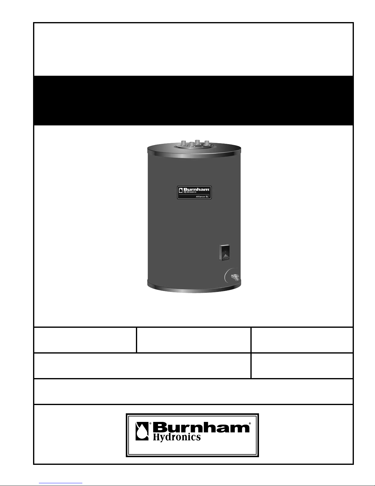
Burnham Indirect - Fired Water Heater AL SL, Alliance 27SL, Alliance 35SL, Alliance 50SL, Alliance 70SL Installation & Service Instructions Manual
...
INSTALLATION, OPERATING AND
SERVICE INSTRUCTIONS FOR
Alliance SL™
Indirect - Fired Water Heater
Including
Warranty
Information
For service or repairs to the water heater, call your heating contractor. When seeking information on the water heater, provide Model Number and Serial Number as shown on Rating Label.
Model Number
AL SL
Heating Contractor Phone Number
Address
100934-01R1-11/07
Serial Number
U.S. Boiler Company, Inc.
Installation Date
Price - $5.00
1
GENERAL INFORMATION
PLEASE READ INSTRUCTIONS CAREFULLY
BEFORE INSTALLING WATER HEATER
U.S Boiler Company, Inc. – Burnham Hydronics (herein called the Company) intends that this Alliance SL™
Indirect-Fired Water Heater be used as a separate zone to a heating system boiler.
This appliance is designed to heat water by circulating water from the boiler through the internal coil in the
tank. We specically do not warrant this tank for high temperature applications such as wood stoves or
steam producing systems. Such use of this product will automatically void the warranty.
The design anticipates the proper installation and care in use of the product. There is risk of property damage and personal injury inherent in the use of any hot water system. The Company cannot supervise the
installation and therefore makes it a specic condition of the warranty that the customer will supervise the
installation and use of this product to be sure they are performed in accordance with safe guidelines and
proper local or national codes.
Generalized instructions and procedures cannot anticipate all situations. For this reason, only qualied
installers should perform the installation. A qualied installer is a person who has licensed training and a
working knowledge of the applicable codes, regulations, tools, equipment and methods necessary for safe
installation of a boiler system and an indirect water heater.
An installation checklist has been provided to help the customer ensure that all procedures for a safe installation have been followed.
If questions regarding installation arise, check with your local plumbing and electrical inspectors for proper
procedures and codes. Local codes take a precedent over instructions in this manual.
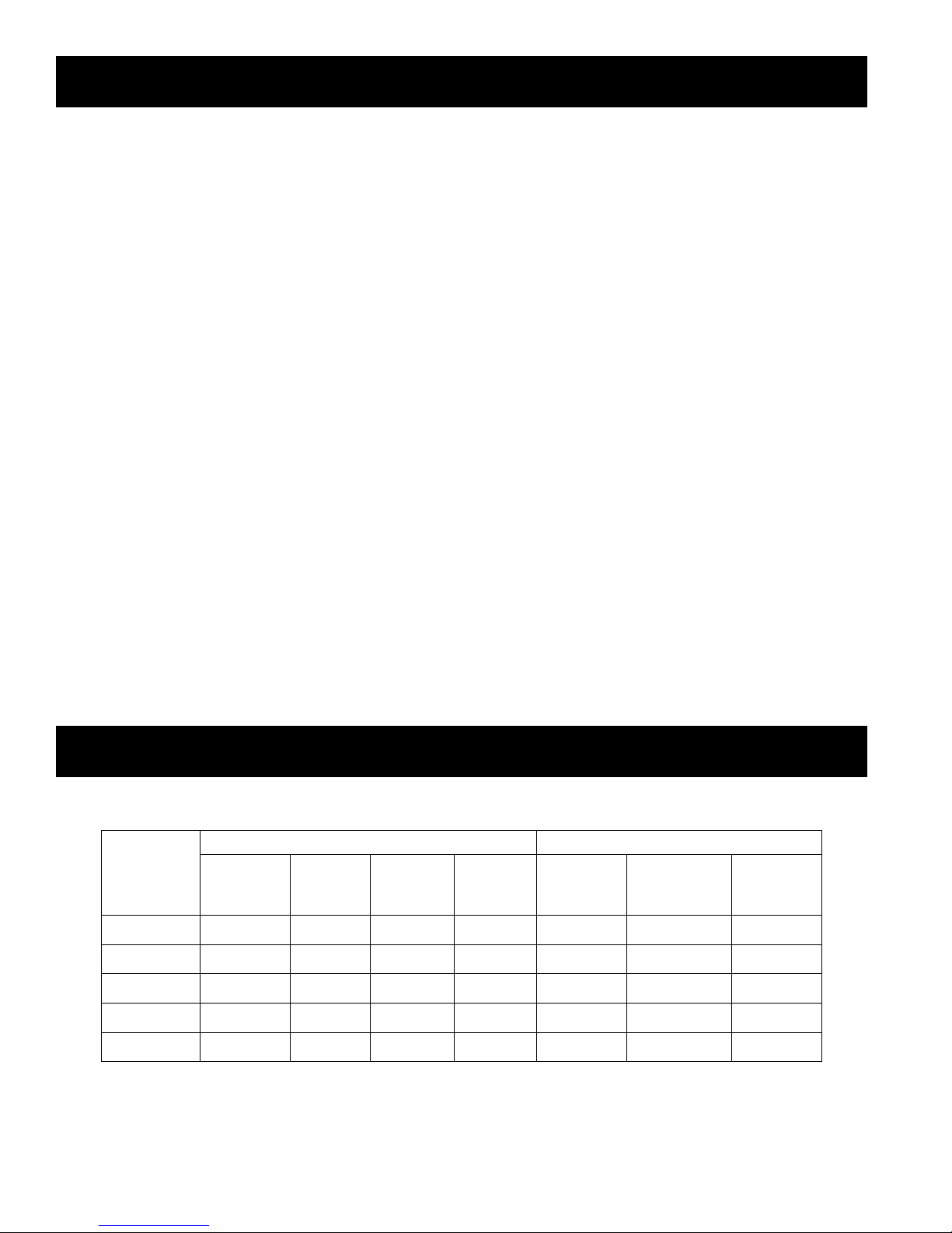
SPECIFICATIONS & RATINGS
Specications Ratings
Potable
Alliance SL
Model
AL 27SL
AL 35SL 35 39.25 22.75 198 200 162 0.72
AL 50SL 50 40.75 26.00 248 225 171 0.56
Volume
(gal.)
27 39.25 20.00 170 192 162 0.97
Height
(in.)
Diameter
(in.)
Weight
(lbs.)
1st Hour
(gal./hr)
Cont. Draw
(gal./hr)
Standby
Loss
(°F/hr)
AL 70SL 70 45.75 28.00 300 294 217 0.45
AL 119SL
2
119 67.75 26.00 480 339 235 0.39
Domestic Water Inlet / Outlet = 3/4”M — T&P Valve = 3/4”F
Boiler Water Supply / Return = 3/4”M — except AL 119SL = 1.0”M
INDEX
General Information ..................................................................................................................... 2
Specications & Ratings .............................................................................................................. 2
Installation Guidelines ................................................................................................................. 4
Installation Checklist .................................................................................................................... 7
Service Information ...................................................................................................................... 8
TPI Control Diagrams (#1-3) ....................................................................................................... 10
Installation Piping Figures (#1 & 2) .............................................................................................. 12
Top Mount Coil Details & Tightening Sequence (Figure #3) ........................................................ 13
Circulator & Burner Control Wiring Diagrams .............................................................................. 14
Zone Valve Wiring Diagrams ....................................................................................................... 15
Switching Relay Wiring Diagrams ............................................................................................... 16
How to Obtain Service Assistance ............................................................................................... 18
Warranty ...................................................................................................................................... 29
Model and Serial Number Information ......................................................................................... 21
Optional Lifetime Warranty .......................................................................................................... Back Cover
To fully understand the purchaser’s responsibilities for
installing the water heater, please read the warranty.
U.S. Boiler Company, Inc., – P.O. Box 3079 – Lancaster, PA 17604
www.burnham.com
3
INSTALLATION GUIDELINES
3/4” x 28” x 28” Plywood
Solid Blocks Under Plywood
A. INSPECTING AND PREPARING THE WATER HEATER
q AL27SL thru AL70SL - Remove the cardboard box, which comes packaged with the heater.
It should contain the following: TPI thermostat, T&P valve and a “Tee”, foamed lid and screws.
q AL119SL - Remove the cardboard boxes, which come packaged with the heater. One box should
contain the following: TPI thermostat, T&P valve and a “Tee”, foamed lid and screws. The other box
should contain the heat exchanger.
B. LOCATION
q Do not place the water heater where there is a risk of property damage in the event of a leak.
q Place the water heater on a solid foundation in a clean, dry location nearest the boiler.
q The water heater should be protected from freezing and water lines should be insulated to reduce
energy and water waste.
q Leave sufcient headroom to service the heat exchanger and electrical controls.
q Do not install in an area where ammable liquids or combustible vapors are present.
q CAUTION: The water heater’s outer jacket is plastic and can melt.
q Do not install in close proximity to wood burning stove or other high temperature apparatus.
NOTE: If Water Heater is Placed On Blocks To Raise It From The Floor,
Be
Sure to Support The Entire Bottom With At Least ¾ “ Plywood On The Top Of The Blocks.
C. PROTECTION FROM WATER DAMAGE
q CAUTION: All water heaters have a risk of leakage at some unpredictable time.
q IT IS THE CUSTOMER’S RESPONSIBILITY TO PROVIDE A CATCH PAN OR OTHER ADEQUATE
MEANS, SO THAT THE RESULTANT FLOW OF WATER WILL NOT DAMAGE FURNISHINGS OR
PROPERTY. (See Figure 1)
D. RELIEF VALVE
q WARNING: A POTENTIAL HAZARD TO LIFE AND PROPERTY MAY EXIST IN ANY WATER
HEATER IF AN APPROVED TEMPERATURE-AND-PRESSURE RELIEF VALVE IS NOT
PROPERLY INSTALLED.
q For protection against excessive pressures and temperatures in this water heater, install tempera ture-and-pressure protective equipment by local codes, but not less than a combination temperature and-pressure relief valve certied by a nationally recognized testing laboratory that maintains
periodic inspection of production of listed equipment of materials, as meeting the requirements for
Relief Valves and Automatic Gas Shutoff for Hot Water Supply Systems, ANSI Z21.22-1971. This
4

valve must be marked with maximum set pressure not to exceed the marked maximum allowable
working pressure of the water heater (150psi). Install the valve into the opening provided and
marked for this purpose in the water heater, and orient it or provide the tubing so that any discharge
from the valve will exit only within 6 inches above, or at any distance below the structural oor and
cannot contact any live electrical parts. The discharge opening must not be blocked or reduced in
size under any circumstances.
q CAUTION: A relief valve is designed to discharge excessively hot water. THE CUSTOMER IS
RESPONSIBLE TO PROTECT PROPERTY AND PERSONNEL FROM HARM WHEN THE VALVE
FUNCTIONS.
q Install the T&P provided on hot water outlet of tank as shown in Figures 1 and 2.
q Care must be taken to be sure that the stem of the pressure-and-temperature relief valve is
immersed in the water within the top 6 inches of the tank.
q The drain line from the relief valve must not be concealed or blocked and must be protected from
freezing.
q WARNING: IF THE WATER SUPPLY IS FROM A WELL, OR KNOWN TO HAVE HARD WATER, IT
IS RECOMMENDED TO USE A PRESSURE RELIEF VALVE IN THE COLD WATER LINE AS
WELL AS A T&P VALVE IN THE HOT WATER LINE.
E. INSTALLING THE REMOVABLE HEAT EXCHANGER
q Heat exchanger is installed at the factory except for the AL119SL which is shipped loose. The
following is provided for servicing or removing the heat exchanger.
q Insert heat exchanger with plastic o-ring housing and align holes in cover plate with holes in ange
and plastic o-ring housing.
q WARNING: Plastic o-ring housing must be properly installed. (See Figure 3). Failure to do
this will void the warranty.
• Insert and secure the bolts to the nuts one at a time in the following manner:
• Place the nut beneath the ange opening.
• Hold the nut in place with one hand – insert the bolt with the other.
• Thread the bolt into the nut and tighten in proper order.
NOTE: Be sure to place bolts in all of the openings.
q Heat exchanger connections are 3/4” male threaded ttings, except for the AL119SL which has 1
inch male threaded ttings.
q Connect the supply line (from the boiler) to the “Hx In” ttings of the heat exchanger. It is recom-
mended to use a union as per Figures 1 and 2.
q Connect the return line (back to the boiler) to the “Hx Out” ttings on the ange of the heat
exchanger. It is recommended to use a union as per Figures 1 and 2.
WARNING: Plastic o-ring housing must be installed properly (See Figure 3) to prevent corrosive
action. Failure to do this will void the warranty. Must use new o-ring if replaced or removed.
F. WATER SUPPLY CONNECTIONS
q WARNING: Some local codes mandate the use of a backow preventer or check valve or
pressure-reducing valve. An adequate expansion tank (or other adequate means) must be
installed to prevent pressure build up or damage from thermal expansion when a check valve
or backow preventer or pressure-reducing valve is used. Failure to do so could result in
tank leakage and therefore void the warranty. (See Figures 1 and 2 for proper location)
q All water supply ttings on this heater are brass – do not over tighten or strip threads.
q It is recommended to use a union as per Figures 1 and 2.
5

q Do not apply heat directly to the cold-water inlet as it is made of plastic and will melt.
G. BOILER SUPPLY CONNECTIONS
q WARNING: Boiler temperature must be controlled by the boiler high limit not to exceed 200°.
Failure to do so will create a hazardous installation and void the applicable limited warranties.
q All water supply ttings on this heater are brass – do not over tighten or strip threads.
q It is recommended to use a union as per Figures 1 and 2.
NOTE: Be sure to connect Boiler Supply Line (from the boiler) to the “HX in” tting and Boiler
Return Line (to the boiler) to the “HX Out” tting.
H. FILLING THE HEATER
q Check that the temperature-and-pressure relief valve has been properly installed (mandatory
requirement).
q Completely close the drain valve.
q Open the highest hot water faucet to allow air to escape from piping.
q Open the valve to the cold-water inlet and allow the heater and piping system to completely ll, as
indicated by a steady ow of water from the open faucet.
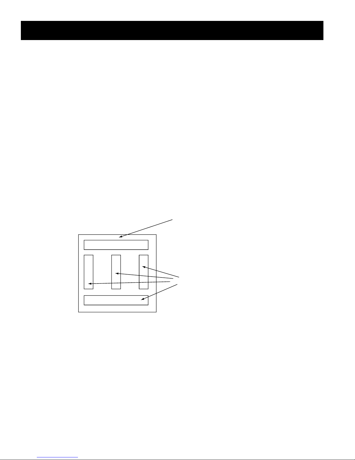
I. TPI THERMOSTAT INSTALLATION
q Attaching TPI Thermostat to tank:
Place hole in back of TPI thermostat over immersion well. TPI thermostat should t ush against the
tank without immersion well protruding beyond cover of TPI case. Use self-tapping screw provided
(Screw A) to attach TPI directly to the Alliance SL tank. (See TPI Diagram 2)
q Inserting the Temperature Sensor:
Slide temperature sensor all the way into the immersion well – until it contacts the end.
(See TPI Diagram 2)
q The sensor will measure temperature adequately by resting against the bottom of the immersion
well.
(Note: Sensor does NOT need to make intimate contact with entire well surface to work properly)
CAUTION: Sensor is soldered directly to TPI. DO NOT BEND SHARPLY OR OVERWORK.
J. TPI WIRING CONTROLS
NOTE: THE TPI CONTROL ELECTRONICS MUST BE POWERED WITH 24VAC.
q Incoming 24VAC power must be connected to 24VAC connectors on the bottom right corner of TPI
Thermostat.
(See TPI Diagram 3)
q The TPI 24VAC only requires 20mA, or about 0.5 Watts.
q Connect control wiring to PUMP/TT normally open relay connections (rated for both 24V and 110V
wiring) on the bottom left corner of TPI control. (See TPI Diagram 3)
q TPI Wiring will vary depending on the type of boiler and valve controls in the system. Consult
attached Wiring Diagrams for appropriate wiring conguration for your system.
q The Alliance SL water heater may operate as a separate heating zone using either the heating
system circulator and an appropriate zone valve, or a separate circulator dedicated for water heating.
(See Figure 1 & 2).
q In both systems, the Alliance SL is controlled through the TPI thermostat on the heater.
(See Figures 1 & 2).
q TPI thermostat calls for the heat when the temperature in the tank is below the set point (120°F) and
either activates a circulator or zone valve depending upon installation design.
6

q Run all 24VAC wiring thru the square notch on bottom of TPI case. (See TPI Diagram 3)
q Incoming 24VAC power must be connected to 24VAC connectors on the bottom right corner of TPI
control. (See TPI Diagram 3)
q Connect control wiring to PUMP/TT normally open relay connections (rated for both 24V and 110V
wiring) on the bottom left corner of TPI control. (See TPI Diagram 3)
q All and only 110VAC wiring must go through an appropriate chase nipple installed in the knockout at
bottom of TPI case.
q Be certain to replace TPI cover using Black Screw provided.
INSTALLATION CHECKLIST
A. INSPECTING AND PREPARING THE WATER HEATER
q Remove the cardboard box, which comes packaged with the heater. It should contain the following:
TPI thermostat, T&P valve and a “Tee”, foamed lid and screws.
B. LOCATION
q Solid foundation and dry location.
q Protect heater water lines from freezing.
q Area free of ammable vapors.
q Sufcient room to service heater.
q Not in close proximity to wood burning stove.
q Where leak will not damage property.
C. PROTECTION FROM WATER DAMAGE
q Be sure to make provisions to protect area from water damage if a leak should occur in the
tank or connected ttings.
D. RELIEF VALVE
q Warning: Improper installation will present potential hazard to life and property.
q Check to be sure that proper relief valve requirements are met.
q T&P installed as shown in Figures 1 and 2.
q 3/4” discharge pipe – properly protected from freezing and restrictions.
q No valve between tank and relief valve or in drain line.
q Provision for hot water discharge from relief valve.
E. INSTALLING THE REMOVABLE HEAT EXCHANGER
q Heat Exchanger is installed at the factory except for the AL119SL. The following is provided for ser vicing.
q Insert heat exchanger with plastic o-ring housing.
q WARNING: Plastic o-ring housing must be installed properly. (See Figure 3).
q For proper installation of Heat Exchanger See Figure 3.
F. WATER SUPPLY CONNECTIONS (See Figure 1 & 2).
q Do not over tighten brass threads.
q Mark the water shutoff for future reference.
7

q Do not apply heat to cold inlet.
q If there is a check valve (sometimes in water meter), backow preventer or pressure-reducing valve,
install an adequate size expansion tank.
G. FILLING THE HEATER
q Completely ll heater.
q Water connections completed and free of leaks.
q Check for proper installation of relief valve.
q Close drain valve.
q Open highest hot water faucet.
q Open cold water inlet valve and ll system.
H. WIRING
See Figure 1 & 2 and separate TPI control wiring diagrams.
q TPI requires 24V to operate. See TPI installation for details.
q Wire either as a heating zone or separate circulator.
q Water heater temperature is controlled by TPI thermostat.
q WARNING: Boiler must have high limit control set no more than 200°F.
SERVICE INFORMATION
WATER TEMPERATURE REGULATION
WARNING: Exposure to 125°F or hotter water can cause scalding injuries. Appropriate caution
must be taken when using hot water. Special supervision must be given to those who cannot act
quickly such as children, disabled or elderly persons.
The input of heat into the tank is controlled by an immersion thermostat. These automatic controls are set
at the factory to maintain a water temperature of 120°F. Note: Although these thermostats are designed to
industry standards, they can fail to control temperature properly without any notice, and therefore should be
tested periodically for your protection.
DANGER: IF YOU DISCOVER EXTREME HOT WATER COMING FROM THE FAUCET, IMMEDIATELY
SHUT OFF THE MAIN SWITCH TO THE BOILER AND CALL COMPETENT SERVICE PERSONNEL.
ANY OVERHEATED WATER IS A POTENTIAL HAZARD TO LIFE AND PROPERTY. DO NOT OPERATE UNTIL THE SOURCE OF THE PROBLEM HAS BEEN DETERMINED AND ELIMINATED.
• Water temperature over 125°F can cause severe burns instantly or death
from scalds.
• Children, disabled and elderly persons are at the highest risk of being scalded.
• See instruction manual before setting temperature at the water heater.
• Feel water before bathing or showering.
Proper maintenance is important for any product. It is suggested that the
purchaser follow the preventive maintenance program outlined below.
8
 Loading...